
Related Manuals for GRAUPNER mx-20 Hott


Summary of Contents for GRAUPNER mx-20 Hott
- Page 1 mx-20 33124. HoTT.1.en H O P P I N G . T E L E M E T R Y . T R A N S M I S S I O N mx-20 Programming Manual...
-
Page 2: Table Of Contents
Table of contents General notices Transmitter initialization ..........38 Cut-off ............. 72 Firmware update ........... 39 Helicopter model ........... 74 Table of contents ............2 Receiver initialization ........... 42 Model name ............ 74 Environmental protection notices ........3 Firmware update ........... 43 Stick mode ............ -
Page 3: Environmental Protection Notices
Satellite operation of two receivers ....218 This manual serves only as a source of information and Sensor Select ............220 can be changed without prior notifi cation. Graupner RF Status View ............ 221 accepts no responsibility or liability for errors or Voice Trigger ............ -
Page 4: Safety Notices
Always use original Graupner handled properly - even if caused by third parties. Preferably, the receiver should be mounted in a readily... - Page 5 Routing the receiver's antenna transmitter's antenna directly toward the model will not voltage that the receiver may falsely interpret a produce good reception but rather degrade reception. throttle signal! This will then cause the motor to The receiver and its antennas must be positioned as far start up unexpectedly.
- Page 6 For further details about interference fi lters, refer to the A remote control system will be destroyed by the not to be used for an extended period of time. Graupner RC main catalog or in Internet at magnetic shock waves produced by a lightning strike - www.graupner.de.
- Page 7 Graupner accepts no form of liability for loss, damage or costs consequential to incorrect usage or operation or • Prior to every fl ight, perform a complete functional which can be attributed to same. test, range test and execute a complete simulated fl...
-
Page 8: Safety Notices And Handling Regulations For Nickel-Metal-Hydride Rechargeable Batteries
Safety notices and handling instructions for nickel-metal-hydride rechargeable batteries As applicable for all highly technical products, • Batteries may only be charged under supervision. • Pay attention that the charging and discharging rules observance of the following safety notices, along with The quick charge current rating for the given type of are followed. - Page 9 Service: Used batteries Henriettenstr. 94 - 96 Discharge D-73230 Kirchheim unter Teck All batteries sold under the Graupner and GM-Racing This represents an essential contribution to trade names are, depending on battery type, suitable for environmental protection. a continuous maximum current load of 6 … 13 C (check the manufacturer's data).
-
Page 10: Foreword
(rudder, elevators) 200 models to be operated simultaneously However, you learn the essential operating steps and functions of the mx-20 HoTT in the least amount of time. and helicopter models (swashplate). Thanks to this because of the interspersed radio-frequency utilization computer technology it is possible to activate these permitted by certifi... -
Page 11: Remote Control Set Description
Computer System mx-20 12 channel remote control s et in 2.4 GHz Graupner HoTT technology (Hopping Telemetry Transmission) • Microcomputer remote control system in modern 2.4 GHz Graupner HoTT technology • Bidirectional communications between transmitter and receiver • Five different languages: German, English, French, coming soon per software update Italian and Spanish. - Page 12 Computer System mx-20 12 channel remote control set with 2.4 GHz Graupner HoTT technology (Hopping Telemetry Transmission) WK, HR QR, WK HR, WK QR and diff. • 24 model memories with storage for all model- •...
-
Page 13: Recommended Chargers
He will be glad to provide 2498.4FBEC 4NH-2000 RX RTU fl at Other charger units and details about the listed chargers can be found advice. in the Graupner RC main catalog or in Internet at www.graupner.de. 33800 HoTT transmitter antenna Introduction - Remote control set... -
Page 14: Transmitter Power Supply
12 hours to recharge at a into contact with one another when the other end of The mx-20 HoTT transmitter has a highly capacitive, current rate equal to one tenth of its specifi ed capacity. the cable is plugged into the transmitter. In order to... - Page 15 Battery operation timer at the bottom left of the screen This timer shows the transmitter's cumulative operating time since the transmitter's battery was last charged. This timer is automatically reset to "0:00" when the transmitter is switched on and its battery voltage is signifi...
-
Page 16: Receiver Power Supply
An overview of available batteries, chargers and current standard installed NiMH battery with an automatic source test instruments can be found in the Graupner charger unit intended for NiCd batteries Monitor the RC main catalog or in Internet at www.graupner.de. -
Page 17: Joystick Length Adjustment
It may be better if unexperienced adjusted to adapt these transmitter controls to the pilot's up on the backplate carefully and turn it open to the right users ask a Graupner Service location to take care of preference. the procedures described below. -
Page 18: Changing Joystick Behavior
Operating notices Converting joysticks Neutralization Both the left and the right joystick can be confi gured collapsible antenna for neutralized or non-neutralized operation as desired. Open the transmitter housing as previously described. To change the joystick's factory setting, locate the screw shown in the fi... - Page 19 Brake spring and ratchet Joystick restoring force The outboard screw of the two marked in the next fi gure The joystick's restoring force can also be adjusted to the adjusts the braking force and the inboard screw adjusts pilot's preference. The adjustment is located next to the the strength of the ratchet for the respective joystick.
-
Page 20: Transmitter Description
Transmitter operating elements Attaching the transmitter's neck strap main status LED There is an eyelet on the top side of the mx-20 HoTT antenna with kink and twist joint transmitter (see fi gure at the right) to which a neck strap eyelet for neck strap can be attached. -
Page 21: Backside Of The Transmitter
For connecting the optionally available Smart-Box, transmitter battery Order No. 33700. Details about the Smart-Box can be found with the given battery compartment cover product in the Graupner RC main catalog or in Internet at www.graupner.de. housing screw housing screw Transmitter description... -
Page 22: Dsc (Direct Servo Control)
The acronym "DSC" is a carryover which stands for the Thus the transmitter is ready for operation. To the contrary, teacher mode for the mx-20 HoTT original "Direct Servo Control" function. However, in removing the battery compartment cover and the HoTT systems the "direct servo control"... - Page 23 "NoName". There is a PC program GRAUBELE Stop 0:00 available on the transmitter's download web page at 0:00 www.graupner.de with which the stored data can be «normal » evaluated on a compatible PC. 5.2V HoTT 3:33h 5.5V Importing voice fi les As already mentioned in the section "Headsets"...
-
Page 24: Display And Keypad
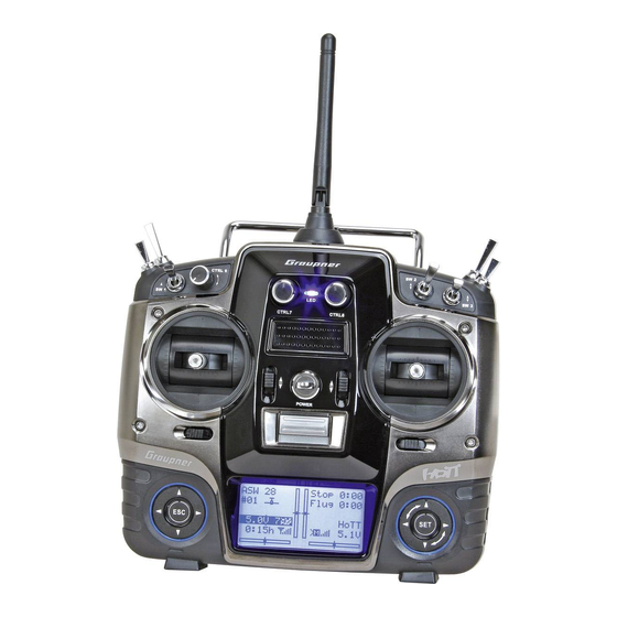
Display and keypad optical indication of trim lever positions or, during activation of speed controls CTRL 7 + 8, an alternative display of the current positions of these controls Model type indicator Model name possible warnings, see page 36 (winged aircraft / helicopter) Stopwatch in min:s Memory location 1 …... -
Page 25: Operating The "Data Terminal
Operating the "data terminal" Entry keys ESC and SET Display symbols Displayed telemetry symbols Keys to the right of the display • button the active model memory has not yet "bonded" with a HoTT receiver. More about the "Binding" After switching the transmitter on, briefl y pressing process, see page 69 or 75. -
Page 26: Shortcuts
Shortcuts The following key combinations can be used to directly keys for a little longer (about 2 s). Model select call up certain menus and options: • Quick-Select Copy / Erase • CLEAR From the multi-function list, a jump can be made to a Suppress menus Brief simultaneous activation of the ... -
Page 27: Hidden Menu Columns
Concealed menu columns Some menus have concealed columns to improve 100% 100% legibility. Menus with concealed columns can be 100% 100% recognized by virtue of a triangle pointing to the right in 100% 100% the bottom left corner of the screen. For example, in the 100% 100% menu "Servo settings": 100% 100%... -
Page 28: Hidden Mode
HIDDEN MODE Language selection and display contrast The mx-20 HoTT transmitter's "HIDDEN MODE" can key in the right touch pad. VOICE TRIGGER be reached from almost any menu position by pressing HIDDEN MODE As mentioned in section "Headsets" on page 21, the and holding the ... -
Page 29: Joystick Calibration
packet downloaded from the transmitter's web page (e.g. Notice: HIDDEN MODE CONTRAST "voice_gb.vdf") into the folder created by the transmitter. • If the warning … LANGUAGE ENGLISH Now take the memory card out of the card reader and VOICE ENGLISH re-insert it into the transmitter. - Page 30 Wait for the notices which typically appear in the base if Control 2 is at its left limit and the other three joystick STICK CALIBRATION screen following a model change then jump to the functions are in their respective middle positions then CONTRAST LANGUAGE ENGLISH...
- Page 31 STICK CALIBRATION CONTRAST LANGUAGE ENGLISH VOICE DEUTSCH STICK CALI. Repeat the calibration process for the right limit of the right joystick. The other joystick planes are calibrated analogously. Notice: • Correct any bad calibrations by repeating the respective process. • Within a given joystick plane, each of the three calibration positions can be selected directly with the ...
-
Page 32: Telemetry Data Display
"T(EMP)1" temperature/voltage RX-VOLT current operating voltage of the found in the appendix and in Internet at www.graupner. sensor, Order No. 33612 or 33613 for General-Engine receiver's power supply in volts de in the web page for the given product. - Page 33 SENSOR 2 (GENERAL + ELECTRIC modules) Vario RXSQ SENSOR 0.0V 0.0m/1s 0m/3s 0°C 0m/10s 0°00.0000 0°00.0000 If attached to the receiver, this display will depict the If attached, this display will depict altitude relative to If attached, this display depicts currently measured data from a GPS module with integrated Vario, Order location or starting location (in m) as well as the current voltage and temperature from a "T(EMP)2"...
- Page 34 No. 33620. More details about this module can be found BAT1 E FUEL F 2:0.00 relative to starting location at which, in the appendix or in Internet at www.graupner.de in the 0.0V 3:0.00 when exceeded, will cause an audible 4:0.00 web page for the given product.
- Page 35 Internet at www.graupner.de in the web page for the given product. Depending on how this module is equipped with sensors, this screen can permanently display the data shown in the table below. The current voltage of up to two batteries (BAT1 and BAT2), the measurement results of up to two temperature sensors (T1 and T2) and a fi...
-
Page 36: Displayed Warnings
Warning notices Warning notices not possible now CAN‘T RECEIVE voltage too low "Bind not available" No bound receiver in range DATA A receiver has not yet been BIND N/A bound to the currently active model memory. Briefl y touching key will cause a direct Connection between teacher jump to the appropriate option. -
Page 37: Function Fi Eld Displays
This lockout is to the left of the two vertical position indicators. established (when the mx-20 HoTT transmitter is displaying its base screen) by simultaneously pressing and holding both the keys for about two seconds. -
Page 38: Transmitter Initialization
If the remote control system is to be operated in this threshold is underrun, Graupner HoTT receiver in the past but there is no France then the transmitter MUST be changed over a warning tone will be sounded and an appropriate connection to this receiver at the moment. -
Page 39: Firmware Update
Current software and information is available in Internet grStudio_Install_VerXX.msi" with a double-click then means that servos connected by way of these at www.graupner.de under the download link for the follow the instructions. channels will remain in their middle positions given product. - Page 40 the desired fi rmware update fi le with a ".bin" fi lename extension from the "Open fi le" window. Firmware fi les are product-specifi cally coded, i. e. if you should accidentally select a fi le which does not correspond to the product (e. g. receiver update fi le instead of a transmitter update fi...
- Page 41 Your notes...
-
Page 42: Receiver Initialization
(red cable) may to be removed from the The mx-20 HoTT remote control set includes a type the form of a uniform beep of about 1 s duration. The 3-pole connector. -
Page 43: Firmware Update
Order No. 7168.6A. The programs and fi les also needed any custom settings that had been present in the can be found in Internet on the Graupner website at receiver before the reset will have to be established www.graupner.de under the downloads for the particular again by way of the Telemetry menu. - Page 44 Typically this fi le can be found in the folder whose name is prefi xed with the order number of the receiver to be updated. This folder should contain the ZIP fi le that was downloaded and unpacked. Its fi lename should also be prefi xed with the order number of the receiver to be updated.
- Page 45 Both LEDs on the receiver will illuminate during the update process. Upon successful conclusion of the update process, the green LED will extinguish and the red LED will begin to blink. Switch off the receiver, remove the interface cable and repeat the process for any other receivers you have which must be updated.
-
Page 46: Installation Notices
The function of every individual channel is determined Servo mounting lug by the transmitter used, not by the receiver. However, Regardless of which Graupner receiver system you use, channel assignments can be changed in the receiver the procedure is always the same. -
Page 47: Receiver System Power Supply
2-cell LiFe battery pack does not present contact resistance. Y-lead PRX stabilised a problem for either Graupner HoTT receivers nor for Order No. 3936.11 receiver power supply Servos present another possible problem source. Even Order No. 4136... - Page 48 The comparatively high nominal voltage, 7.4 V, for a 2-cell LiPo pack does not present a problem for either Graupner HoTT receivers nor for those servos, speed controllers, gyros and other devices which have been specifi cally approved for operation in this – higher –...
- Page 49 Your notes...
-
Page 50: Term Defi Nitions
Term defi nitions Control function, control, function input, control channel, mixer, switch, control switch, fi xed switch To make use of this mx-20 HoTT manual easier, a The proportional operating elements produce a direct Switches number of the terms used repeatedly throughout this... - Page 51 Fixed switches FXI and FX This type of switch turns a function permanently on, e. b. timers (closed fi xed switch) or off (open fi xed switch) or they can provide a fi xed input signal for a control function, e. g. FXI = + 100 % and FX = -100 %. For example, in fl...
-
Page 52: Switch And Control Assignments
Physical control, switch and control switch assignments Principle procedure The mx-20 Hott system exhibits maximum fl exibility Changing switch action push desired switch when it comes to assigning standard equipment If the activation of a switch is to result in the opposite into position ON operating elements to specifi... - Page 53 The control switches, freely programmable in the Control/fix sw "Control switch" menu, can be incorporated into switch programming, i. e. assigned to a function instead FXi C1i C2i C3i C4i of a "normal" switch. At those program locations Use the arrow keys in the left or right key pad to select where switches can be assigned you always have the the desired switch then assign it with a brief tap on the opportunity to assign one of the control switches, C1...
-
Page 54: Digital Trimming
Digital trim Functional description and description of C1 cut-off Digital trim with visible and audible indicators 1. Winged models 2. Helicopter models C1 trimming has a special cut-off trim function intended In addition to the "Cut-off trim" function described Both joysticks are equipped for digital trimming. When especially for combustion motors. - Page 55 Your notes...
-
Page 56: Winged Models
Winged models Convenient support is provided for up to four aileron tail fl aps – each controlled by a separate servo – which In addition to 8 freely allocatable linear mixers, 4 servos and four fl ap servos on normal models or, for handles both elevator and ruder functionality. - Page 57 Installation notices … and tail plane type "V tail unit" Because of orientation differences for installed servos and their rudder linkages, the actuating direction of Servos MUST be connected to the receiver in the Free or right flap 2 or aux. function some servos may be initially backward.
-
Page 58: Helicopter Models
fl ight phase. The beginner will initially only adapt the fl ight phase. Control 6 – the proportional rotation control, The mx-20 HoTT program can operate all hover fl ight point to the control middle for the non-linear CTRL 6 top left – is assigned to input 12 by default. This conventional helicopters having 1 …... -
Page 59: Receiver Layout
Notice for those transitioning from older Graupner Receiver layout for helicopter models … All menus relevant to helicopter models are marked systems: in the "program descriptions" section with a helicopter … with 1 to 3 swashplate servos In comparison to previous receiver layouts, servo symbol …... -
Page 60: Loading A New Memory Location
Detail program description Loading a new memory location Anyone who has worked through to this part of Select model type the manual has certainly already tried out a bit of free programming. Nevertheless a detailed description of free ... - Page 61 the transmitter is switched on again the undesired notice that no failsafe settings have yet been made. as well as rolling, pitching, tail rotor and throttle/pitch occupation of the that model memory will have to be More about this can be found on page 192. for helicopter models, to the two joysticks.
- Page 62 CTRL 6 – . This condition changes for both model types only after the respective assignments have been made in the "Control adjust" menu. On the other hand, if a newly initialized model memory is to be put into operation then it MUST fi rst be appropriately "connected"...
-
Page 63: Model Select
Model select Call up model 1 … 24 The basic operation of the transmitters keys was not possible now GRAUBELE explained on pages 24 and 25 and, on the previous ULTIMATE voltage too low double-page, explanations were provided for navigating STARLET to the multifunction list and about how to occupy a new BELL47G... -
Page 64: Copy / Erase
Copy / Erase Erase or copy model model, copy from or to SD card, copy fl ight phases Copy model model Select the "Copy / Erase" menu with thearrow BASIC SETTINGS, MODEL keys of the left or right touch pad then briefl y press the Select the "Copy model ... -
Page 65: Export To Sd Card
Once selection of the model memory has been Export to SD Notice: confi rmed by pressing the button, a confi rmation Select the "Export to SD" sub-menu with the arrow • Should the notice … request will appear. keys of the left or right touch pad and press the SD-CARD button. -
Page 66: Import From Sd Card
Import from SD by its copy without establishing the bond again. impor t to model: Select the "Import from SD" sub-menu with the GRAUBELE Copy from phase arrow keys of the left or right touch pad and press ULTIMATE Select the "Copy from phase" sub-menu with the the SET button. -
Page 67: Suppress Menus
Suppress menus Suppress models Hide menus in the multifunction Hiding model memory locations Select the "Suppress menus" menu with the arrow Select the "Suppress models" menu with the arrow Model select keys of the left or right touch pad then briefl y press the keys of the left or right touch pad then briefl... -
Page 68: Base Setup Model
Motor full throttle Stick forward selection so that you can change to another line. RF transmit Bound receiver Graupner HoTT receivers must be "instructed" to Stick back Motor idle Motor idle Stick back Change to the next screen page by pressing the communicate exclusively with one particular model button briefl... -
Page 69: Binding Receivers
Use the arrow keys of the left or right touch pad Multiple receivers per model can be bound if desired, Mod.name GRAUBELE whereby respective mx-20 HoTT programs offer the to move to the screen's "RF bind" line" then select the Stick mode potential for managing a maximum of two receivers desired binding channel. -
Page 70: Receiver Output
Afterward, return again to the "RF BIND" line receivers" section, the mx-20 HoTT offers both the BUT CAUTION: If, for example, you have already and restart the process to dissolve bond as described opportunity to freely divide up the transmitter's control specifi... -
Page 71: Rf Transmit
Important notice: between OFF and ON. Again pressing the center RECEIVER CH – BIND2 By using the mx-20 HoTT transmitter's "Tx. output button in the right touch pad will complete the entry. Input 4 Out Ch13 swap " option the transmitter's 12 control functions... -
Page 72: Dsc Output
Rcv Ch Map % the case, do not use the system. Contact your RF transmit Cut-off area's Graupner GmbH & Co. KG service partner. RF Range Test 99sec Depending on the "idle forward or back" choice made Perform the range test before each fl ight and, in in the "Motor at C1"... - Page 73 ON position. speed controller, alone by the switch to be assigned in the right column. The speed controller or throttle servo will remain in this cut-off position only until the selected switch is However, if you wish to set a lower threshold, by which again changed over followed by a one-time throttle an underrun will cause the throttle servo or speed servo or speed controller movement beyond the preset...
-
Page 74: Helicopter Model
"MODE 2" (throttle left) Mod.name TS-Nick Motor/Pitch Motor/Pitch Nick Bound receiver Stick mode Graupner-HoTT receivers must be "instructed " to RF BIND communicate exclusively with one particular model RF transmit Nick Motor/Pitch Motor/Pitch Nick (memory) in a Graupner-HoTT transmitter. This "MODE 3"... -
Page 75: Binding Receivers
HoTT programs offer the "Binding" the transmitter and receiver BASIC SETTINGS, MODEL Use arrow keys of the left or right touch pad to potential for managing a maximum of two receivers Mod.name STARLET directly and for dividing up the 12 control channels (max) move to the screen's "RF bind"... -
Page 76: Receiver Output
Afterward, return again to the "RF BIND" line receivers" section, the mx-20 HoTT offers both the BUT CAUTION: If you wish to operate two servos with and restart the process to dissolve bond as described... -
Page 77: Rf Transmit
At the same time, the timer display in the a distance of up to about 50 m. transmitter's screen will start counting down and Perform the range test on the Graupner HoTT system every 5 seconds a two-frequency tone will sound. Notice: according to the following instructions. -
Page 78: Dsc Output
fl ight simulator or teacher/pupil system. This maximum this option, as described on page 52. If a switch is area's Graupner GmbH Co. KG service partner. is control channels 1 ... 5 if "PPM10" is selected, control assigned, it will have absolute priority over all other Perform the range test before each fl... -
Page 79: Auto.c1 Pos
Within the framework of autorotation settings for the Autorotation ––– close the carburetor's throttle servo only to the extent mx-20 HoTT transmitter's helicopter program, there Auto.C1 Pos. -55% ––– dictated by the value in the left column as soon as are parameters for an emergency "cut off"... - Page 80 BASIC SETTINGS, MODEL BASIC SETTINGS, MODEL DSC Output PPM10 DSC Output PPM10 Autorotation ––– Autorotation ––– Auto.C1 Pos. -55% Auto.C1 Pos. -55% cut off –100% +150% ––– cut off –125% +100% ––– Finally, use the column at the right to specify a Programming switch with which you can cut off the motor directly To change the preset "cut-off"...
- Page 81 Your notes...
-
Page 82: Model Type
Model type Establishing winged aircraft model type This "Model type" menu is used to establish the settings" sub-menu of the "Wing • C1 trimming will operate according to your choice type of model to be programmed. This also activates mixers" menu (beginning page 146) is between "normal"... - Page 83 controlled instead by way of the "Dual video. Now use the arrow keys of the right touch pad to Brake offset mixer" menu, page 194. In this case select the number of wing servos to be programmed for This function not only has potential for gliders and however, the tail type entry specifi...
- Page 84 infl uence any mixer available for "Brake settings" in the "Wing mixers" menu. This free travel ensures that, even if the brake fl ap control is not quite positioned to its full end of travel, it will still stop all brake settings at "neutral".
- Page 85 Your notes...
-
Page 86: Helicopter Type
Helicopter type Establishing helicopter model type Simultaneously pressing the or keys of the This "Model type" menu is used to establish the "1 Servo": The swashplate will be tipped with one type of model to be programmed. This also activates servo each for roll and nick. - Page 87 strain for different displacement positions due to travel Swashplate type: 3 Servos (2 Nick) which deviates from one another. Linearizing will require a bit of familiarization on the part of the pilot because, in order to linearize the entire rotation travel for the servo arm, servo travel can be appropriately reduced for small control movements –...
- Page 88 The "Pitch min" line is used to adapt the direction of • Since your models will typically be operated with the # operation for the throttle/pitch control stick to your same pitch-min direction, this specifi cation can be control preferences.
- Page 89 Your notes...
-
Page 90: Servo Adjustment
Servo adjustment Servo direction, midpoint, travel and limit This menu is used to set the direction, neutralization, pad to complete the entry. Column 3 "midpoint" pressing the or keys of travel and limit parameters for a given selected servo Simultaneously The servo midpoint setting is intended for adapting a exclusively. - Page 91 Simultaneously pressing the or keys in frame. the right touch pad (CLEAR) will reset the entry fi eld Notice: displayed in inverse video back to its "0 %" value. It may be necessary to fi rst assign a control to a servo attached to one of the 5 ...
-
Page 92: Stick Mode
Joystick setting Setting stick mode 1 through 4 Both joysticks are equipped for digital trimming. With can be made with the arrow keys of the right touch pad. GRAUBELE Stop 0:00 each brief push (one "click") on a joystick it will change 0:00 Column "Tr"... - Page 93 touch pad, the corresponding entry fi eld will be framed. sides or separate for each control direction. This setting For example: has a programmable range of 0 s to 9.9 s. In the case of side-separate settings, the joystick is to be moved to the Ch.1 0.0s 0.0s...
-
Page 94: Helicopter Model
Joystick setting Setting stick mode 1 through 4 Both joysticks are equipped for digital trimming. With Scroll with the arrow keys of the left or right touch pad to Ch.1 0.0s 0.0s each brief push (one "click") on a joystick it will change the "... - Page 95 "GL": The position of the respective trim lever with the arrow keys of the right touch pad. For example: A rash "Pitch" control movement would not operate is effective for the given model "globally", the nick servo in the middle as quickly as it would the Thr.
-
Page 96: Control Adjust
Aside from the two joysticks which operate control select and assign these "other" operating elements as functions 1 through 4, a standard mx-20 HoTT value. desired and leaves any unused operating elements Briefl... - Page 97 Column 2 "typ" control's number or – in conjunction with a switch Input 5 ––– symbol indicating the switching direction – the switch's Analogous to the "Stick mode" menu already described, Eing. 6 ––– Move desired switch number . this column can be used to select whether other settings Eing.
- Page 98 covers travel to both sides of the marked frame. Input 5 +100% +100% Input 5 +100% Input 6 +100% Input 6 Input 5 +100% +100% Input 7 +111% +88% Input 7 Input 6 +100% +100% Input 8 +100% +100% Input 8 Input 7 +100% +100%...
- Page 99 Detail program description - Control adjust...
-
Page 100: Helicopter Model
In addition to the two dual axis sticks for control can select any of the "additional" transmitter controls functions 1 to 4, the mx-20 HoTT transmitter is Briefl y tap the center key on the right touch pad. - Page 101 "GL(obal)" or a "PH(ase-specifi c)" effect, as follows: move them for slightly longer. If the control does not Column 4, "offset" have enough travel, move the control in the opposite In this column, you change the control center, i. e. the Input 5 –––...
- Page 102 If you tap the or keys on the right touch pad To confi gure asymmetric travel, move the affected Input 5 transmitter control (proportional rotary control or switch) (CLEAR) at the same time, this will reset parameters Throt to the side on which you wish to confi...
- Page 103 "Throt 6" " Gyro 7" conditions – or to test-fl y optimum settings. In software terms you can even limit the gyro gain range in both Input 5 ––– Input 5 ––– directions by adjusting transmitter control travel. Throt ––– Throt –––...
-
Page 104: Throttle Limit Function
Throttle limit function control using either the CTRL 7 or 8 proportional rotary "Thr.l 12" anything near its idle speed under "normal" fl ight control. conditions, and that the motor can therefore neither be As standard, the "Thr.l 12" input is assigned to the CTRL started or stopped cleanly without some other means of 6 proportional rotary control mounted on the top left of intervention. -
Page 105: Idle Setting
The throttle servo must not move as well! Any further direction as far as it will go. Use the trim lever on the throttle servo on the mx-20 HoTT! adjustments to the throttle curve must of course be throttle/collective pitch stick to move the trim position made later in fl... - Page 106 Last idle position touch pad. Bear in mind that servo output 6 controls Current trim position using a switch and not the default CTRL 6 proportional the throttle servo on the mx-20 HoTT! Throttle limit control GRAUBELE stop 0:00 rotary control.
-
Page 107: Stick Mode" Menu
Throttle limit in conjunction with "Thr AR" on the "Stick mode" menu As already explained on page 94, selecting "Thr AR" in limiter fully closes the carburetor, i.e. the motor is safely Input 9 the "Thr." line on the menu … switched off at this control position. -
Page 108: Dual Rate / Expo
Dual Rate / Expo Confi gurable control characteristics for aileron, elevator and rudder Using the arrow keys on the left or right touch pad, page between 0% and 125% of the normal full travel. you can clearly see the dependency of the curve value to the menu option "Dual Rate / Expo"... - Page 109 control switches" (page 52): the word "DUAL" (shown roughly in the middle of the 111% display) changes to "EXPO": ––– 100% ––– 100% ––– 100% ––– 100% ––– Move desired switch DUAL ––– 100% ––– to ON position normal DUAL –––...
- Page 110 Some examples of Expo values: Activate "Switch assignment" and tap the center key briefl y on the right touch pad to switch to Expo = +100% Expo = +50% Expo = –100% ––– the expanded switches. Here, use the arrow keys to –––...
- Page 111 ––– 100% 111% ––– 100% DUAL normal Set the Expo values in the same way. Detail program description - Control adjust...
-
Page 112: Helicopter Model
Dual Rate / Expo Confi gurable control characteristics for roll, pitch-axis, tail rotor Using the arrow keys on the left or right touch pad, page functions of arbitrary complexity. directly. Once you select a menu line, the dotted vertical to the menu option "Dual Rate / Expo" in the multi- line follows the movement of the respective joystick, so The control travels for each switch position can be set to function list:... - Page 113 use the key on the left or right touch pad to move icon at the lower edge of the display, as described highlighted fi eld separately for each of the two switch in the section "Assigning transmitter controls, switches positions: to the right beyond the Dual Rate value column, until and control switches"...
- Page 114 Some examples of Expo values: Activate "Switch assignment" and tap the center Roll key briefl y on the right touch pad to switch to Expo = +100% Expo = +50% Expo = –100% Nick ––– the expanded switches. Here, use the arrow keys to Tail –––...
- Page 115 Roll ––– 100% Nick 111% Tail ––– 100% DUAL normal Set the Expo values in the same way. Detail program description - Control adjust...
-
Page 116: Channel 1 Curve
Channel 1 curve Control characteristics for throttle/spoiler joystick Using the arrow keys on the left or right touch pad, page along the path of joystick travel. While the on-screen C1 Cur ve to the menu option "Channel 1 curve" in the multi- graph considerably simplifi... - Page 117 the right touch pad (CLEAR) and then delete the value. already set. In this case, a triangle is shown on the C1 Cur ve Complete the operation by briefl y tapping the center key graph to indicate each point jumped to. The arrow keys Trim offset on the left touch pad.
- Page 118 Smoothing the Channel 1 curve key on the right touch pad or the center on the left touch pad: In the example below, sample reference points have been set: C1 Cur ve Reference point 1 to 0% Cur ve Reference point 2 to +25% Input –50% Reference point 3 to -75%...
-
Page 119: Helicopter Model
Channel 1 curve Control characteristics for throttle/collective pitch stick Using the arrow keys on the left or right touch pad, page along the path of joystick travel. While the on-screen Up to 4 additional reference points can be set between to the menu option "Channel 1 curve"... - Page 120 Deleting reference points point, please note that the percentage value on the C1 Cur ve "Output" line always relates to the current joystick To delete one of the reference points (1 to max. 4), use Trim offset position. the joystick to move the vertical line into the vicinity Input of the reference point in question.
- Page 121 does not refer to the repositioned point, however: C1 Cur ve instead, it signifi es that a further point can be set at Cur ve the current control position. Input –50% • Please note that the percentage value on the Output "Output"...
-
Page 122: Switch Display
Switch display Displaying switch positions Using the arrow keys on the left or right touch pad, transmitter housing. The numbering of the switches page to the menu option "Switch display" in the multi- has no effect on the programming of the transmitter, function list: however. -
Page 123: Control Switch
5th column. Assigning a transmitter control to a control switch The mx-20 HoTT program is equipped with a total of Tap the center key on the right touch pad to open Using the arrow keys on the left or right touch pad, the menu shown below: 4 of these control switches ("C1"... - Page 124 vice versa: CONTROL SWITCH CONTROL SWITCH +85% ––– ––– CONTROL SWITCH ––– ––– +85% ––– ––– ––– ––– ––– ––– ––– ––– The switching point can be altered at any time by Resetting a control switch back to "free" tapping the center key on the right touch pad again.
- Page 125 • FIf a control switch – e. g. "C1" – has multiple This diversity of switching options certainly offers you CONTROL SWITCH assignments, you should bear in mind that the enough scope for specialized applications to suit any –75% switching direction set here applies to all C3 type of model.
-
Page 126: How Do I Program A Fl Ight Phase
How do I program a fl ight phase? The concept of fl ight phase programming General information on fl ight phase programming Once these are set, you can then move to the fl ight "Helicopter mixers" phase-dependent menus (see the tables below) to During a fl... - Page 127 Detail program description - Control adjust...
-
Page 128: Phase Settings
Phase settings Setting up fl ight phases Using the arrow keys on the left or right touch pad, Setting up fl ight phases "Name" column page to the menu option "Phase settings" in the multi- When you set up fl ight phases for fi xed-wing aircraft Briefl... - Page 129 changes of phase, however, although it can be stopped activating the switch itself. Activating the switch, BRAKE SETTINGS during any fl ight phase via the center key on the in turn, increments the counter by 1 and restarts left touch pad. the "Time2"...
- Page 130 Using the arrow key on the left or right touch pad, Note: move the marker frame over the "ph. Tim." column – and The "switch time" set here applies uniformly to all "Motor" column, if applicable – to the right. settings that are specifi...
- Page 131 Detail program description - Control adjust...
-
Page 132: Helicopter Model
Clk 1, Clk 2, Clk 3, Lap, Time1, Time2 modifi ed as appropriate. Within one model memory, the mx-20 HoTT lets you The fl ight phase timers "Clk 1 … 3" plus "Time1" and program up to 6 discrete groups of settings for various "Name"... - Page 133 page 142) is "closed". The frequency at which the same time (CLEAR) will reset the display of stopped Example: the switch is activated is shown on the basic timers on the basic display. Auto Autorot 5.5s display. This counter fi eld is highlighted as soon "Sw.
-
Page 134: Phase Assignment
Phase assignment Setting up fl ight phases Using the arrow keys on the left or right touch pad, page will have set up names for your phases. On this menu – always be assigned from the center point position. to the menu option "Phase assignment" in the multi- which is identical for both model types –... - Page 135 Use the arrow keys on the left or right touch pad to the default phase name as "1 Normal" for this switch move the marker frame down and to the right and then position. briefl y tap the center key on the right touch pad: You can leave this menu in the familiar way by pressing the center key on the left touch pad.
-
Page 136: Phase Trim" (Winged Model)
Phase trim Flap settings specifi c to fl ight phases Using the arrow keys on the left or right touch pad, page – determines the line that is chosen. An asterisk marks Normal to the menu option "Phase trim" in the multi-function the fl... -
Page 137: Non-Delayed Channels
Non-delayed channels Channel-dependent delays to switching Using the arrow keys on the left or right touch pad, page Use the arrow keys on the left or right touch pad to to the menu option "Phase trim" in the multi-function move the "" onto the corresponding channel and then list: briefl... -
Page 138: Timers (General)
Timers (general) Timers on the basic display The default transmitter display shows a total of three This timer is automatically reset to "0:00h" when the Non-delayed chan timers. These are: the transmitter operating time on the transmitter detects that the voltage of the battery is Timers (general) left of the display, plus a "Top"... - Page 139 "Stop (watch)" or "Motor (runtime)" timer. To stop the timer, fi rst ensure the timer switch is Model time 12:34h ––– at its OFF position. Then, press and hold the arrow keys Both of these two timer variants can be started and Batt.
- Page 140 Switching between "forwards" and "backwards" Complete your input by tapping the center key. Model time 12:34h ––– or keys on the right touch If you tap the Timer runs forwards (stopwatch function) Batt. time 1:23h pad at the same time (CLEAR), this will reset any Stop –––...
- Page 141 • If you change timer functionality, these changes are made active by pausing the timer(s) and then tapping the or keys on the right touch pad at the same time (CLEAR) to reset them. • Remember that the timer switches also remain active during programming.
-
Page 142: Flight Phase Timers
Fl. phase timers Selecting and setting The discussion of the "Phase settings" menu on page any switch to these timers, and the same is true of the programming mode. 134 has already described how timers can be assigned "lap counter/timetable" timer: Switching between "forwards"... - Page 143 Alarm timer the new changes to settings are made active only after GRAUBELE Stop 0:00 the timer(s) have been stopped on the basic display and 0:00 Timer1 0:00 ––– by then tapping the or keys on the right touch «Speed »...
- Page 144 • If you should forget to switch off the lap counter in a phase which is now not currently active, simply press the center button on the left touch pad. To swap between the basic display and the "Lap Display" … 01:23.4 00:00.0 02:34.5...
-
Page 145: What Is A Mixer
Left rudder / elevator V-tail mixer Right rudder / elevator Rudder stick The mx-20 HoTT transmitter software contains a large number of pre-programmed coupling functions as standard, which are designed to mix together two (or more) control channels. Accordingly, the mixer named in the example just above can be activated in the "Tail"... -
Page 146: Wing Mixers
Wing mixers Calibrating the wing fl ap system Within the menu tree of the menu … then the fl ight phase name, e. g. "Normal", will appear on "MIX-only channel" (see page 193) and use it for the lower edge of the display: another purpose with the help of a "free mixer"... - Page 147 connected to outputs 9 and 10 – assuming that To confi gure symmetrical mixer values, move the Accordingly, specify the input 1, 7, 8 or 9 and the offset corresponding fl aps have been specifi ed on the transmitter control or joystick to its center position, so corresponding to your customary piloting in the "Brake "Aile/fl...
- Page 148 Mixer functions defl ection also generates drag and therefore further a "split" position – can be suppressed entirely. This reduces the aircraft's effi ciency. approach not only reduces or even suppresses "adverse The individual options on the "Wing mixers" menu yaw", but can, in certain circumstances, even generate option are discussed below, separately for single-, dual- If, on the other hand, a differential is applied to the...
- Page 149 Diff. (camber-changing fl ap differential) Model type: "1AIL" exception of a "pointer" to the "Elevat curve" sub-menu. Accordingly, we proceed immediately further from here If you have entered "1AIL" for the "Aile/fl aps" line on the by once again tapping the center key on the right "Model type"...
- Page 150 direction of defl ection as appropriate. Optionally, this Model type: "1AIL 1FL" the C1 joystick. mixer can be activated and deactivated by using one of If you have entered "1AIL 1FL" for the "Aile/fl aps" To confi gure the setting, fi rst position the brake control in the switches that do not reset themselves (SW 2 …...
- Page 151 Here, you can set the degree to which the rudder follows defl ected downwards when the elevator is oriented possibly fl ight phase-dependent – then this also affects commands acting on ailerons. This is used in particular upwards and vice versa for a downward-oriented this mixer.
- Page 152 Model type: "2AIL" "AILE" column. You should utilize these options by … Brake If you have entered "2AIL" for the "Aile/fl aps" line on the • … moving the transmitter control for "Brake" Cur ve off "Model type" menu (page 82), then the "Wing mixers (see description for "Model type"...
- Page 153 popular with slope fl yers, where ailerons alone are often to the rudder. a control switch. used for turning the model. The adjustment range of ± 150% lets you set the To confi gure symmetrical mixer values, move the direction of defl ection as appropriate. Optionally, this elevator joystick to its center position, so that the mixer can be activated and deactivated by using one of marker frame surrounds both value fi...
- Page 154 Model type: "2/4AIL 1/2/4FL" opposite direction for fl aps. fl.pos If you have entered "2AIL 1FL" for the "Aile/fl aps" Before we address the details of this menu we would +100% +100% line on the "Model type" menu (page 82), then the like to provide a brief explanation of the different display "Wing mixers menu"...
- Page 155 … are shown, and – one further "step" to the right – all +100% options for the second fl ap pair as well: Ail-tr +100% Diff. fl.pos left left left right right right Ail-tr Diff. fl.pos Normal +100% +100% AILE Since the options available on the "wing mixer menu"...
- Page 156 type" menu (see page 82), then the abbreviations "AI", +100% "AI2", "FL" and "FL2" refer to the following fl aps: Ail-tr +100% Ail-tr Diff. Diff. fl.pos fl.pos +100% +100% left left left left right right right right Normal Normal AILE FLAP …...
- Page 157 (Aileron fl aps) A I +100% +100% (Not shown for "2AIL 1FL".) Ail-tr +100% Ail-tr +100% Diff. Diff. +100% fl.pos fl.pos Ail-tr +100% Normal Diff. AILE fl.pos Normal Normal AILE AILE Ail-tr Accordingly, you must fi rst specify your desired elevator Diff.
- Page 158 F L (Effects of fl ap controls) regardless of the direction of rotation of the aileron and +100% fl ap servos. In this line, you specify the percentage rate with which Ail-tr +100% If you tap the or keys on the right touch the settings for input 6 (as made on the "Control Diff.
- Page 159 on the "Control adjust" menu. However, you can assign changed in the active (highlighted) fi eld back to the 1, 7, 8 or 9, depending on the input that you have a transmitter control or switch to this input at any time default value (see screen images).
- Page 160 • "AILE" column • To activate two airbrake servos, the best approach is to leave one servo on output 1 and to connect the When braking the model as it comes in to land, second servo to a free output of your choice – for neither of the two aileron fl...
- Page 161 in this way as far as possible, you should ensure that By briefl y tapping the center key on the right touch +100 % you make use of the automated "Differential reduction" pad, you can switch to the display screen as shown below: feature.
- Page 162 Aileron rudder Flap elevator In each case, you should test the setting selected at the appropriate altitude and re-adjust as required. As WING MIXERS WING MIXERS you do, however, ensure that your model does not slow Multi-flap menu Multi-flap menu down excessively with the braking system extended! Brake settings...
- Page 163 Detail program description - Control adjust...
-
Page 164: Helicopter Mixer
Helicopter mixers Flight phase-specifi c setting of collective pitch, throttle and tail rotor On this menu … the auto-rotation phase – the typical helicopter mixing Description of helicopter mixers and coupling functions shown in the screen-shot To confi gure collective pitch curve settings and the two Fl. - Page 165 (maximum pitch at +100% control travel): at the same Pitch Pitch time, the current joystick position is shown numerically Cur ve off Cur ve off on the "Input" line (-100% to +100%). Input Input The point at which the vertical line crosses the curve is Output Output termed the "Output", and can be varied at the maximum...
- Page 166 Trim point function Pitch Pitch Alternatively, assuming the value fi eld is active, i. e. Cur ve off Trim offset highlighted, you can use the up or down arrow keys Input –50% Input on the left touch pad to jump to reference points Output –12% Output...
- Page 167 Deleting reference points value fi eld on the "Curve" line: Pitch To delete one of the reference points (1 to max. 4), use Cur ve off Pitch the joystick to move the vertical line into the vicinity of Input Cur ve the reference point in question.
- Page 168 This will fully isolate the throttle servo from the "without idle-up", and with the associated "waste" of a throttle curve with the throttle limit proportional rotary fl ight phase for this purpose – since the mx-20 HoTT 168 Detail program description - Control adjust...
- Page 169 control turned fully to the left; the motor will be idling Helicopter with speed GOVERNOR Throttle and respond only to C1 trim. This option permits you Unlike speed controllers, which merely adjust the Cur ve off to start and also stop the motor from within any fl ight output level –...
- Page 170 C1 Tail present and set – are erased. Following this, the (Static torque compensation) Tail reference points "L" (input = -100%) and "H" (input Cur ve off Tail = +100%) are then each set to the same value, for Input +100% Cur ve off...
- Page 171 Here, too, requires the throttle to follow suit: major cyclic control the mx-20 HoTT program lets you confi gure settings to motor power, however, to avoid a fall-off in system movements also require this, i. e. if the swashplate is rotational speed.
- Page 172 fl ying habits. For the Graupner/JR gyro NEJ-120 BB, order no. 3277, this position, well before full tail rotor defl ection. With this option, the effect of the gyro sensor ("gyro") both the upper and the lower values are set via rotary can be varied according to the tail rotor joystick position;...
- Page 173 control limits. Here too, for purposes of illustration, we effect of the vertical fi n combined with the gyro may Swashplate rotation plot gyro gain values in relation to tail rotor defl ection also lead to an overreaction that once again manifests Nick Throttle for various parameter values of gyro suppression.
- Page 174 The swashplate mechanism may then strike its end- stops and in the worst case the ball-links could even be disengaged. The mx-20 HoTT transmitter contains a confi gurable software function for limiting the total swashplate travel, i.e. it restricts the tilt angle of the swashplate from 100% (the travel is limited to the value obtainable either with roll or pitch-axis alone) to 149% (no effective limit).
-
Page 175: Adjusting The Throttle And Pitch Curve
fl ight attitude below the center. control response and low noise when hovering In the mx-20 HoTT program, the trim lever of control • Higher rotor speed for aerobatics with motor power Idle setting and throttle curve function 1 acts principally only on the throttle servo. - Page 176 safety precautions applicable to handling motors 2. The model lifts off before the center point is pitch setting for the hover and the maximum collective and helicopters before starting the motor for the reached. pitch setting (point "H") now provides you with a simple fi...
- Page 177 hovers below the mid-point, correct this by reducing the Once the model can fl y this maneuver properly, set the blades spinning wildly. angle of attack appropriately. value for "Throttle min" – the value for point "L" on the Always make sure that nobody else graph page for "C1 ...
-
Page 178: Autorotation Setting
Helicopter mixers Auto-rotation settings Auto-rotation permits both full-size and model that the auto-rotation settings comprise a complete speed into a descent at an angle of around 60–70° helicopters to land safely in a crisis, e. g. if the motor seventh fl ight phase, which provides access to all the when collective pitch is reduced to a minimum. - Page 179 value on this line so that a glow motor is held at a safe Depending on the friction and running resistance of the idle during the auto-rotation phase without the clutch gearbox, the fuselage may still yaw slightly, however. This engaging;...
-
Page 180: General Remarks About Freely Progr. Mixers
Particularly in its output. Normally, the neutral point is the center mentioned, the mx-20 HoTT offers a number of freely the latter case, however, it is very important to ensure point of the transmitter control. However, the offset... -
Page 181: Free Mixers
Free mixers Freely-programmable linear and curve mixers to the menu option … Regardless of the model type you have selected, each Basic programming procedure of the 24 model memory slots will offer you eight linear Select the mixer you want by using the arrow keys Fl. - Page 182 Defi ne the mixer ratios on the second screen page. the previous page. center button on the right touch pad: Return to the fi rst page by using the center After assigning a control function or the "S" switch on the left touch pad. channel in the "fr"...
- Page 183 If you intend to assign a control switch (G1 … G4) as b) The same mixers WITH series switching: Trim Effect on mixer output a switch, then please note that you must defi ne this Linear, over full trim lever travel appropriately BEFOREHAND on the "Control switch"...
- Page 184 not only also switchable, but can even be subject to a N.N.* 7 The servo pair 6 + 7 responds with an delay, by assigning an appropriate delay in the "– time aileron function +" column of the "Control adjust" menu. For more N.N.* ...
-
Page 185: Linear Mixers
• Use the option available to you at any time of consulting the above table. Leave the default value of switching to the "Servo display" menu (see "GL" in the "Type" column alone, however, to confi gure page 230). This menu is reached from almost any this setting globally for all fl... - Page 186 the value zero over the entire stick travel; accordingly, Symmetrical mixer ratios L.MIX 1 the elevator will not yet follow the movement of the fl aps. The next task is to defi ne the mixer values above and Mix input First, the …...
-
Page 187: Curve Mixer
L.MIX 1 L.MIX 1 C.MIX 9 Mix input Mix input Cur ve off +20% +20% +55% +20% Input –45% Offset Offset Output –100% Point ? normal If you were now to reset the offset currently set at -100% Note: Setting reference points back as far as 0% of control travel –... - Page 188 irrelevant, since the reference points are continuously activating the value fi eld on the "Point" line by briefl y C.MIX 9 renumbered automatically from left to right as they are tapping the center key, use the arrow keys on the Cur ve off entered.
-
Page 189: Examples
does not refer to the repositioned point, however: Note: C.MIX 9 instead, it signifi es that a further point can be set at The curves shown here are for demonstration purposes Kur ve Trim offset the current control position. only and are not at all representative of real mixer Input +35% curves. - Page 190 … to the mixer confi guration page. Decouple the assigned transmitter control from MIX ONLY CHANNEL On this page, use the arrow key on the left or control channel 9 on the "MIX-only channel" menu, however, to ensure that any servo connected to right touch pad to select the line under "Offset"...
- Page 191 Detail program description - Control adjust...
-
Page 192: Mix Active/Phase
MIX active/phase Selecting mixers for fl ight phases Using the arrow keys on the left or right touch pad, page respective mixer is set to "--" by using the arrow keys on to the menu option … the left or right touch pad, then this mixer is deactivated in the fl... -
Page 193: Mix Only Channel
MIX-only channel Separating control functions from control channels for all fl ight phases Using the arrow keys on the left or right touch pad, page adjust " menu. Examples: to the menu option … Conversely, a joystick, transmitter control (CTRL 6 … •... -
Page 194: Dual Mixer
Dual mixers Same-sense/opposite-sense mixing of two control channels Using the arrow keys on the left or right touch pad, page be possible with time-consuming programming of free Elevator stick to the menu option … mixers. Here, we will use a "V-tail with rudder differential" as Fl. - Page 195 affects both servos. If the rudders are also required to defl ect outwards when the airbrakes are activated, then you should assign the C1 stick (transmitter control 1) to input 8 on the "Control adjust" menu. Finally, move to the "Offset" column and adjust the offset value until both rudders return to the neutral position.
-
Page 196: Swashplate Mixer
Swashplate mixer Fail-safe Collective pitch, roll, pitch-axis mixer Using the arrow keys on the left or right touch pad, page pitch, pitch-axis and roll independently of one other, Using the arrow keys on the left or right touch pad, page to the menu option …... - Page 197 last received correct signal, temporarily stored in the Successful storage of the positions is confi rmed briefl y FAIL SAFE receiver. This feature is confi gured by the settings as on the screen: described below. This feature also suppresses brief FAIL SAFE interference caused by e.
-
Page 198: Teacher/Pupil
Teacher/pupil Connecting two transmitters for trainer mode with a trainer lead Using the arrow keys on the left or right touch pad, page to Teacher-pupil settings switches, SW 1 or SW 9, so as to be able to revert the menu option "Teacher/pupil" on the multi-function list: control back to the teacher transmitter at any time. - Page 199 If you wish to transfer other control functions to the pupil HoTT teacher transmitter FIRST BEFORE PLUGGING can be found in Graupner's RC main catalog and on the transmitter in addition to the functions of the two dual THE CONNECTION CABLE INTO THIS UNIT. If you do www.graupner.de website.
- Page 200 DSC module, order no. 3290.24) teacher transmitter connection has been lost. ) to a Graupner pupil transmitter with an The basic display also displays the following warning optoelectronic pupil socket (identifi able by notice …...
-
Page 201: Connection Schematic
Trainer mode with the mx-20 transmitter Due to the continuous improvements made to the product range, please consult our website at www.graupner.de for the latest information Pupil transmitter mx-20 HoTT Teacher transmitter mx-20 HoTT HoTT Trainer lead Trainer lead Trainer lead Trainer lead order no. -
Page 202: Wireless Hott System
Wireless HoTT system The mx-20 HoTT trainer mode system can also be Channel Function Swaschplate mixer operated wirelessly. To do so, the teacher transmitter Fail-Safe adjust Motor throttle/collective pitch must be "connected" to a pupil transmitter as described Teacher / pupil Aileron/roll below. - Page 203 Teacher transmitter TRAINER /Pupil TRAINER /Teach Up to twelve control functions of the teacher transmitter "Teach" can be transferred to the pupil transmitter Pupil Pupil pupil "Pupil", either individually or in any combination. Teach Teach signal The lower display line, named "Teach", therefore refers 8 9 10 11 12 8 9 10...
- Page 204 show "ON" instead of the fl ashing "BINDING": persons could reduce the connection range of the return channel used by the two transmitters. Furthermore, you pupil TRAINER /Pupil should remember that the return channel assigned for signal wireless trainer mode functionality is normally used for –...
- Page 205 If, on the other hand, you use the arrow keys on the left or right touch pad to select "ACT" … Please selcet trainer link? … and confi rm this selection by tapping the center key on the right touch pad, then the existing teacher connection is restored.
-
Page 206: Tx. Output Swap
To achieve maximum fl exibility regarding receiver socket right touch pad at the same time (CLEAR), you can assignment, the mx-20 HoTT program offers you the restore the original assignment. option of swapping servo outputs 1 to 12 as you please. - Page 207 Detail program description - Control adjust...
-
Page 208: Telemetry
Note: functions can also be assigned with distribution to receiver is only exchanged after the fourth data After registering your product at https://www.graupner. multiple receivers or multiple receiver outputs can package, the data transmission requires a certain de/de/service/produktregistrierung you are automatically... -
Page 209: Setting& Data View
S-STR Signal strength in % mx-20 HoTT. The few differences are described in the receiver. Therefore, switch on your receiver system R-TEM. Receiver temperature in °C... - Page 210 receiver system and the position of the antenna. entered into fail-safe mode. L.R-VOLT Lowest operating voltage of the The reception power should not drop below -90 dBm receiver since it was last turned on, in Receiver operating voltage (R-VOLT) during operation. Otherwise, reduce the distance of the volts Always check the operating voltage of the receiver.
- Page 211 RX SERVO the channel set here. selected in the "OUTPUT CH" line. The setting for both directions takes place in a range of RX SERVO Reverse (servo reversal) 30 … 150 %. OUTPUT CH: 01 Set the rotational direction of the servo connected to the REVERSE : OFF Factory setting: 150 % each.
- Page 212 Control channels 2 and 5 for the left safe And then another brief notice regarding the three and right aileron. The corresponding INPUT CH of possible versions of the mx-20 HoTT transmitter for Positions of all the receiver, which must also be mapped, would be control channels the setting of Fail Safe: the channels 02 and 05 in this case;...
- Page 213 on the channel set in the OUTPUT CH line. of the right touch pad. The adjustment takes place in safe position you assigned or want to assign in the line 10-µs increments. "MODE" "FAI(L) SAFE". The current position of the The factory setting for all servos is "HOLD".
- Page 214 Therefore, the servo connections 6, 7 and 8 of a RX FAIL SAFE Value Explanation Possible settings OUTPUT CH: 04 receiver are mapped with one another, whereby the MASTER CH Signal source or 0, 1 … depending INPUT CH: 04 OUTPUT CH (servo connections) 06, 07 and 08 are MODE : FAI-SAFE...
- Page 215 "Dual Rate / Expo", page 108, of the transmitter mx-20 HoTT, two curves must be set: tail unit fl aps – each controlled with a separate servo – assume both the elevator and rudder function.
- Page 216 RX SERVO TEST ALL-MAX (servo travel on the "+" side) RX CURVE CURVE1 CH In this line you set the maximum servo travel on the plus RX SERVO TEST TYPE : side of the control travel for the servo test. ALL–MAX : 2000μsec CURVE2 CH...
- Page 217 By pressing the central SET key of the right touch pad, operated in a cycle of 20 ms – with a 12-channel RX DATAVIEW VOLT.E S–QUA100%S–dBM–030dBM you now start the test run. The input fi eld is shown as receiver (Order No. 33512) 30 ms – regardless of S–STR100% R–TEM.+28°C "normal"...
-
Page 218: Satellite Operation Of Two Receivers
BEFORE commissioning a model. of the right touch pad for the channel selection. www.graupner.de. With this selection you specify the highest of the This receiver combination is recommended, if, for Through this connection, all channels of the HoTT... - Page 219 remains controllable when the SUMO satellite receiver no longer receives a signal. Telemetry data, such as the voltage of the onboard electricity supply, on the other hand, is only sent to the transmitter by the satellite receiver confi gured as SUMO. Therefore, telemetry sensors are to be connected to the satellite receiver (SUMO).
-
Page 220: Sensor Select
SENSOR SELECT After selection of the desired menu line with the arrow keys of the left or right touch pad… TELEMETRY TEL.RCV rcv ch1 SETTING & DATA VIEW SENSOR SELECT RF STATUS VIEW VOICE TRIGGER … and then pressing the central key of the right touch pad, the selected submenu opens: SENSOR SELECT... -
Page 221: Rf Status View
RF STATUS VIEW After selection of the desired menu line with the arrow reception power since switching on the transmitter keys of the left or right touch pad … or the resetting of the display by simultaneously pressing the keys or of the right touch pad TELEMETRY (CLEAR). -
Page 222: Voice Trigger
VOICE TRIGGER After selection of the desired menu line with the arrow VOICE TRIGGER VOICE TRIGGER keys of the left or right touch pad … REPEAT 5SEC REPEAT 5SEC TRIG ––– TRIG TELEMETRY VARIO ––– VARIO TRANSFER TRANSFER TEL.RCV rcv ch1 RECEIVER RECEIVER... - Page 223 the "SENSOR SELECT" submenu: TX VOLT: MODEL TIME: VOICE TRIGGER BATTERIETIME: REPEAT 5SEC TIMER(GE.)TOP: TRIG TIMER(GE:)CENTER: VARIO TIME: TRANSFER RECEIVER SENSOR RECEIVER If, for example, the "VARIO" sensor was selected, after After selection of the desired menu line with the arrow selection of the "SENSOR"...
-
Page 224: Basic Settings
General settings Basic transmitter settings Using the arrow keys of the left or right touch pad, scroll • "Pitch min" ! " # $ % & ’ ( ) + , – . / 0 1 2 to the "Basic Settings" menu item of the multifunction …... - Page 225 Helicopter model stick mode memory in the line "DSC Output" the same way as with BASIC SETTINGS "Stick mode". “MODE 1” (Throttle at right stick) “MODE 2” (Throttle at left stick) H-J Sa n d br u n ner If necessary, using the arrow keys of the left or Stick mode pitch axis throttle...
- Page 226 In order to guarantee the optimal visibility of the display Simultaneously pressing the arrow keys or of the mx-20 HoTT in any weather and at any you are offered a suitable voltage range in the (next) line of the right touch pad (CLEAR) resets the inverse fi eld "Battery warning".
- Page 227 Make sure that you do not enter a value which is too Touch sensitivity Voice volume low, so that you still have suffi cient time to safely land BASIC SETTINGS BASIC SETTINGS your model in the event of a battery warning. Batterie type Ni-MH Power on warn.
- Page 228 228 Detail program description - Control adjust...
- Page 229 Detail program description - Control adjust...
-
Page 230: Servo Display
Bar 2 = Aileron or left aileron correspond to the 12 control channels available in the Code lock Bar 3 = Elevator mx-20 HoTT transmitter. The number of actually info display Bar 4 = Rudder usable channels, however, depends on the receiver Bar 5 = Right aileron By briefl... -
Page 231: Servo Test
Servo test Function test of Servo 1 … 8 Scroll with the arrow keys of the left or right touch pad to time of 0.5 s. SERVO TEST the menu item "Servo test" of the multifunction menu: To change the cycle time, select the time input fi eld with the arrow keys of the left or right touch pad. -
Page 232: Code Lock
Otherwise, the transmitter must be sent in to secr et num b er (1234) Graupner Service for decoding. The lock becomes active the next time the transmitter is switched on. However, the control remains ready for operation. Calling the multifunction list and thereby The fi... - Page 233 lock, you should, if applicable, remove this menu from CODE LOCK the multifunction list with "Suppress menus" so that De sire d ( new) unauthorized persons cannot enter a secret code "on Memorise secret secr et number the sly". none ...
-
Page 234: Info Display
PC program provided for the respective The current version number of the transmitter software of the left or right touch pad and then briefl y press the product on the internet page at www.graupner.de. is shown in this line. central key of the right touch pad. - Page 235 1234MB on page 39, the date and time can also be set through the PC program provided for the respective product on the internet page at www.graupner.de. Display of the available storage space in MB. • The date and time are protected against data loss...
-
Page 236: Programming Examples Introduction
HoTT programming Preparatory measures based on the example of a winged model Programming models in an mx-20 HoTT … corresponding activated wing mixer – see the following because they have more of a stabilizing and controlling pages – can be assigned with both the fl ap function and function than a braking function in this type of crow …... - Page 237 – even in the approach. The selection is not or vice versa, the rotational direction of the throttle servo diffi cult with the mx-20 HoTT transmitter. or brake system do not have to be adapted as well. For the control of the motor you use a two-stage switch In addition, with an "idle front/rear"...
-
Page 238: Winged Model
Initial steps for the programming of a new model Example: Winged model with two ailerons and – initially – without motor propulsion In the scope of the initial commissioning of a new transmitter is switched on or after the last key actuation. "Select model"... - Page 239 • If the battery voltage is too low, you cannot switch actual model programming in the "Mod. Name" line: "Motor at C1" models for safety reasons. A corresponding message • "none" BASIC SETTINGS, MODEL appears in the display: Trimming works independently of the joystick position Mod.name and the "Brake settings"...
- Page 240 "AI RU" mixer (aileron to Aileron or left aileron • The maximum possible throw of a Graupner servo Airbrake or throttle servo rudder), and the two signals can combine to have an or speed controller (electric motor) is 150% per side, based on both mechanical and excessive effect.
- Page 241 menu … with only two servos in the wings, the Multi-fl ap menu BRAKE SETTINGS beginning on page 157 is not shown. "Joystick setting" is not only interesting for pilots of Crow D.red models with motors. (page92) WING MIXERS Elevat cur ve Brake settings Ch.1 0.0s...
- Page 242 just the model! In case of doubt, ask the advice of an "Channel 1 curve" (page 116) Brake experienced model pilot. Cur ve on Cur ve Input –19% Cur ve off Output –6% If you should fi nd during the testing that one or multiple Input Point 1 –7%...
- Page 243 "Fail safe" menu (page 196) FAIL SAFE hold 1 2 3 4 5 6 DELAY : 0.25s … because "doing nothing" is the worst thing which can be done for a winged model. In the transmitter's home position, "Hold" is specifi ed and "Hold"...
-
Page 244: Incorporating An Electric Drive
Integration of an electric drive into the model programming L.MIX 1 Input 5 ––– Mix input Input 6 ––– Input 7 ––– Offset Input 8 ––– offset A common option in the following examples 1 ... 5, the Notice: An electric drive can be controlled in different ways: automatic tracking of the elevator trimming in the power The adjustment of a curve mixer is described in detail in The simplest method to integrate one such drive into... - Page 245 the selected control close to "Full throttle" so that the ""Servo adjustment" (page 90) Input 5 ––– marking frame is only placed around one value fi eld. Input 6 ––– 100% 100% Now enter a value of at least 1 s, ... Input 7 –––...
- Page 246 setting" and "Phase assignment" menus, the Like with example 1, you also switch to the line of a free manner for each active fl ight phase. Otherwise, you settings described above must be made in the same input, activate the "Control and switch assignment" in may wonder why the drive motor begins running at manner for each active fl...
-
Page 247: C1 Joystick Switchover Between Electric Motor And Butterfl Y
Control E-motor and crow alternatingly with C1 joystick Example 4 corresponding brake offset in the menu ... M O D E L T Y P E Before we discuss the programming of this fourth ""Model type" (beginning on page 82) Motor at C1 vorne example or turn the to the expansion of the previously... - Page 248 menu. For example, you name the phase for the front Pha1 Nor mal Clk 1 Pha1 Normal 1.1s switch position "normal" and "landing" for the rear Pha2 – Landing Pha2 – Landing 1.1s position (or vice versa): Pha3 –...
- Page 249 line "Aile.diff." With the "Elevat curve" mixer the normally occurring "Upward tilting" of the model on the raising of the ailerons can be automatically suppressed. The suitable correction values for the respective value must be tested out through fl ight. Set this mixer so that the fl ight speed of the model does not change too much with the brake system extended in comparison with the "normal"...
-
Page 250: Electric Motor And Airbrake
C1 joystick switchable between E-motor and spoiler Example 5 key of the left key pad or the central key of the right fl ap servos – just as we intended. touch pad and then switch to the center column to the If, contrary to the assumptions of the preceding Example left. - Page 251 Detail program description - Control adjust...
-
Page 252: Timer Activation By Control Or Switch
Timer confi rmation with control or switch Examples 4 and 5 of the preceding pages CONTROL SWITCH Model time 0:34h ––– If you have decided to continue with the model –85% Batt. time 1:23h ––– programming on described on the previous pages for Stop –––... - Page 253 point at the selected position by briefl y pressing the Model time 0:34h ––– Model time 12:34h ––– central key of the right touch pad. The switch status Akkuzeit 1:23h Batt. time 1:23h Control/fix sw is shown to the right of the control number: Oben: Stopp –––...
-
Page 254: Parallel Operating Servos
Servos running in parallel A second servo running in parallel is often required, Then connect one of the two servos to Output 1, control is connected to a free (receiver) Output 5 ... such as when brake fl aps or spoilers installed in the provided for this purpose by standard, and the second 12. - Page 255 "Control adjust" menu (page 96) Then switch to the graphic screen and set a symmetric M O D E L T Y P E mixture of +100%. Motor at C1 None Input 5 ––– Tail type 2ELSv3+8 L.MIX 1 Input 6 –––...
-
Page 256: Using Fl Ight Phases Example 1
Use of fl ight phases Up to seven different fl ight phases (fl ight statuses) Example 1 ... Initially, one or multiple fl ight phases are provided with can be programmed with settings independent of one a specifi c identifi cation ("Name") for the respective …... - Page 257 to enable a "smooth" transition of the various servo PHASE ASSIGNMENT PHASE ASSIGNMENT positions. Thus, an increased stress of the model under prior combi prior combi certain circumstances with a "hard" change of rudder or fl ap positions, for example, is prevented The "Status" column shows you the currently active fl...
- Page 258 Here, select the menu item "Copy fl ight phase" with the Input 5 ––– Normal arrow keys and then briefl y press the central key of Thermal Input 6 ––– the right touch pad. Speed Input 7 ––– In the appearing window, "Copy from phase", "1 Normal" Launch Input 8 –––...
- Page 259 BRAKE SETTINGS Crow +30% D.red +33% Elevat cur ve Normal AILE … and enter how wide the ailerons should be raised in the "Crow" line. With "D.red" (differentiation reduction), you should enter the value previously set in the aileron differentiation line in order to suppress it again while breaking.
-
Page 260: Example 2
Use of fl ight phases Example 2 … Begin with the new programming of the model in a free control path is automatically spread to 100 %. model memory location. In the menu … Glider with four fl ap wings, two large fl aps and tow In the menu "Base setup model", connect your receiver coupling "Control adjust"... - Page 261 curve" menu has as little effect on this input as brake fl .pos. In this line you set the fl ight-phase specifi c +66% offset set to less than 100 %, which you can check very fl ap positions for all fl aps available on the Ail-tr +66% easily in the "Servo display"...
- Page 262 mixers" menu ... suppress it again during braking. Pha1 Nor mal Elevat curve In this line you set another correction Pha2 – Thermal BRAKE SETTINGS value for the elevator, see page 162. Pha3 – Speed Crow +44% +66% Insofar as necessary, check and adjust all fl ap throws, Pha4 –...
- Page 263 By briefl y pressing the central key of the right PHASE ASSIGNMENT PHASE ASSIGNMENT touch pad, switch the window to the entry of the prior combi prior combi target memory "Copy to phase". Select phase "2 Thermal" as the target: Copy to phase: 1 Nor mal 3 Speed...
- Page 264 changing fl aps (6 + 7) are moved continuously with a Input 5 +60% mixer proportion to be set in the "Wing mixers menu. Ail-tr +60% Input 6 Diff. +33% Input 7 Input 5 ––– Input 8 fl.pos –14% Input 6 Normal +15% +15%...
- Page 265 of mixture specifi ed for the example compensates directly for the FL-pos. setting, whereas … • … in the other limit position, AIL and FL reach the maximum downward offset prescribed by the mixer percentage. In order to set a – corrective – admix for the elevator, exit the "Multi-fl...
-
Page 266: Control Of Temporal Processes
Control of temporal processes using time delay and curve mixers A useful, but less known capability of the mx-20 … delayed lighting of a headlight after the beginning MIX ONLY CHANNEL HoTT software is the ability to activate nearly any servo of the extension of the landing gear: movements with a maximum duration of 9.9 seconds only... - Page 267 … triggered by the same switch, but with a delayed Input 9 startup of the drive motor connected to Output 10: Input10 Input11 C.MIX10 Input12 Cur ve Input –100% – time + Output –100% Point L –100% Notice: normal In the course of the switch assignment, always bear in mind that you can also trigger multiple functions with The function you programmed functions as desired one switch! For example , with the same switch a landing...
-
Page 268: Eight-Fl Ap Wing
Eight-fl ap wing By standard the mx-20 HoTT supports the For the control of all fl aps, up to two additional +55% comfortable control of up to eight servos for the aileron/ proportional rotary controls are required in addition to... - Page 269 … if necessary. to set variable camber changing fl ap positions for +90% each fl ight phase with a proportional rotary control, In doing so, the basic programming of the eight-fl ap Ail-tr +90% wing is completed. … you can additionally vary the basic settings of all Diff.
- Page 270 If you have assigned the same control to the inputs Input 5 +25% +25% +77% 5, 6 and 11 – as specifi ed above – all eight fl aps move +25% Ail-tr +77% Input 6 +25% simultaneously while the elevator follows the set degree Diff.
- Page 271 11 + 12 extend upward and the camber changing fl ap position, you should automatically suppress any pairs "FL" (6 + 7) and "FL2" (9 + 10) extend downward, programmed aileron differentiation. whereas the elevator is trimmed in parallel to this, see For this purpose, use the "Differentiation reduction"...
-
Page 272: Delta And Fl Ying Wing Models
Delta and fl ying wing models Of course, the general comments regarding the These settings specifying the model type affect the Free or aux. function or right flap 2 / elevat Free or aux. function or left flap 2 / elevato installation and the adjustment of the RC system to a available "Wing mixers"... - Page 273 Delta/fl ying wing of the type: "2 AIL 1 / 2 / 4 FL" on ailerons and camber changing fl aps. Diff. The setting of a differentiation is rather tricker due to the fl.pos M O D E L T Y P E model type and should only take place based on a feel Motor at C1 None...
- Page 274 In order to now achieve this with the mx-20 Hott, versa. With appropriate adjustment of the "leading" "Cross-mixer" (page 194) switch to the "Brake settings" of the … mixer to the setting of curve mixers in order to achieve a …...
- Page 275 "Only mix channel" (page 193) ... for safety's sake! Corresponding with the above example, therefore, the control channel 5 should be set to "only MIX": MIX ONLY CHANNEL only normal 1 2 3 4 5 6 Detail program description - Control adjust...
-
Page 276: F3A Model
F3A model F3A models are a part of the group of motor-driven for the carburetor can – if necessary – be provided. You "Servo adjustment" (page 90) winged models. They are powered by a combustion or normally use one of the two proportional rotary controls 100% 100% electric motor. - Page 277 After test-fl ying and trimming of the model, we Input 5 ––– ––– +33% recommend reducing the trim travel for the elevator and ––– +33% Input 6 ailerons The model has signifi cantly less of a reaction ––– +33% Input 7 to a movement of the trim lever.
- Page 278 MIX 2: -5 % ... -10 % . of mx-20 HoTT. If, for example, the model rotates menu ... away to the right over the longitudinal axis with the Example L.MIX 1: rudder extended in knife-edge fl...
- Page 279 Asymmetric setting. The appropriate values must be Turning away with the ailerons/landing fl aps on page 196, you can defi ne a "Fail-safe position" for tested in fl ight. extended each of the individual servo outputs of your receiver (Fail-safe mode). Relatively small mixer values are usually suffi...
-
Page 280: Helicopter Model
Batterie type Ni-MH reading anyhow! With the exception of the omitted idle programming of the mx-20 HoTT. The following Batterie war ning 4.7V settings, you can practically adopt most of the settings Power on warn. - Page 281 change these in the adopted defaults "Stick mode", not possible now "DSC output" and "Pitch front/rear" as well as within free voltage too low the respective model memory location. free free The setting the "Contrast" line determines the legibility Once this fi...
- Page 282 Notice: "3Sv(2rol)". Please note that with the newer Graupner mc and key of the right touch pad and move one of the two- mx remote control systems the fi rst pitch servo and The lineLinear swashpl."...
- Page 283 100% 100% • ith the user of the "throttle limiter" function, you with a model changeover and with the mx-20 HoTT 100% 100% do not have to program a fl ight phase "throttle and even with a change of the fl ight phase).
- Page 284 Then switch to the "Travel" column with the arrow keys ""Helicopter mix" (page 164 … 179) Pitch of the left or right touch pad and increase the now Cur ve off Pitch inversely highlighted value from +100 % to +125 % with Input Throttle a fully opened throttle limiter after briefl...
- Page 285 fl ight phase name "Autorot" A rotor adjustment gauge, such as the Graupner somewhat at the minimum limit position. The throttle appears – the "old" pitch curve is again: adjustment gauge, Order No.
- Page 286 points; everything else is reserved for the experienced Pitch Input 5 ––– pilot. For this purpose, change the presetting intended Thr setting AR –90% Throt ––– for heading lock systems from a uniform 0 % at point Tailoffset AR Gyro "L"...
- Page 287 "Channel 1 curve" (page 119) Further settings precedence over any other phases you assign switches to. Following this programming example, you have provided However, in the "Name" column you fi rst assign Cur ve a helicopter with a basic adjustment for the hovering "meaningful"...
- Page 288 PHASE ASSIGNMENT to carry out changes in the phase-dependent menu prior combi PHASE ASSIGNMENT for each individual phase. Since the mx-20 HoTT Autorot prior combi has digital trimming, in addition to the fl ight-phase dependent menu settings in the helicopter program,...
- Page 289 It is mandatory for the transmitter-side programming that the rotational speed regulator was installed and programmed according to the manufacturer's instructions. Of course, the mx-20 HoTT also enables further possibilities for the realization of different speeds in the individual phases. For a practical recommendation with maintenance of the throttle limiter function, see the description beginning on page 169.
-
Page 290: 290 Appendix
• Suitable for fi ve or six-cell NiMH or two -cell LiPo or LiFe batteries. Vario technical data: • Resolution: 0.1 m Graupner/JR, G3.5, G2 and BEC plug systems. • Altitude measurement: -500 m … +3000 m • Vario sensitivity: 0.5 m/3s, 1 m/3 s, 0.5 m/s, 1 m/1 s, 3 m/s •... - Page 291 Order No. 33620 General sensor for Graupner HoTT receivers and models with General sensor for Graupner HoTT receivers and models with General sensor for Graupner HoTT receiver and models with electric combustion or electric motor: combustion or electric motor: motor •...
- Page 292 BOX your future smart companion. Whether it comes to displaying adapter cable, Order No. 7168.6A, for the updating of receivers and sensors and the mx-20 HoTT transmitter can be updated directly real-time telemetry data or settings are made on your HoTT system, 8 x 21 characters on a large display enable easy use.
-
Page 293: Fcc Information
FCC Information Graupner mx-20 HoTT #33124 • Connect the equipment into an outlet on a circuit different from that to which the receiver is connected. FCC ID: ZKZ-MX-16-20A • Consult the dealer or an experienced radio/TV FCC Statement technician for help. -
Page 294: Declaration Of Conformity
Declaration of Conformity 294 Declaration of Conformity... -
Page 295: Warranty Certifi Cate
Mängel, da wir Ihnen bei Mängelfreiheit die entstandenen Unkosten in Rechnung stellen müssen. Übergabedatum: Ceská Republika Schweiz Graupner GmbH & Co. KG, Henriettenstraße 94 - 96. D-73230 Date of purchase/delivery: Slovenská Republika Graupner Service Kirchheim/Teck, Germany guarantees this product for a period of Date d’achat :... - Page 296 D-73220 KIRCHHEIM/TECK provided. No liability is accepted for print errors. Graupner reserves the right to change the described hardware and software features at GERMANY any time without prior notifi cation.
Need help?
Do you have a question about the mx-20 Hott and is the answer not in the manual?
Questions and answers