Sign In
Upload
Manuals
Brands
NEC Manuals
Telephone
NEC Dterm Series E
NEC NEC Dterm Series E Manuals
Manuals and User Guides for NEC NEC Dterm Series E. We have
6
NEC NEC Dterm Series E manuals available for free PDF download: User Manual, Installation Manual, Manual
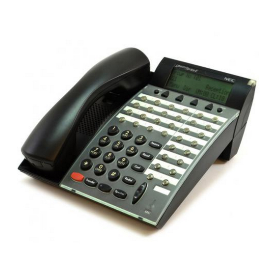
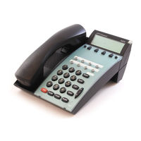
NEC NEC Dterm Series E User Manual (1190 pages)
Brand:
NEC
| Category:
Telephone System
| Size: 6 MB
Table of Contents
Table of Contents
9
Section 1 about this Chapter
16
Chapter 1 Introduction
21
General Information
21
Multiline Terminals Used with the System
21
Chapter 2 Features
25
About this Chapter
25
Important Notes
26
IPK to IPK II Feature Comparison List
27
Features
36
Account Code Entry
37
Default Settings
38
Account Code - Forced/Verified/Unverified
43
Alarm
51
Alarm Reports
55
Alphanumeric Display
67
Analog Communications Interface (ACI)
69
Ancillary Device Connection
77
Answer Hold
81
Answer Key
83
Attendant Call Queuing
85
Automatic Call Distribution (ACD)
87
Default Setting
98
Required Software
99
Automatic Release
105
Automatic Route Selection
107
Background Music
119
Barge-In
121
Battery Backup - System Memory
125
Battery Backup - System Power
127
Call Appearance (CAP) Keys
129
Call Arrival (CAR) Keys
133
Call Duration Timer
137
Call Forwarding
139
Call Forwarding - Centrex
151
Call Forwarding/Do Not Disturb Override
155
Call Forwarding, Off-Premise
157
Call Forwarding - Park and Page
169
Call Forwarding with Follow Me
173
Call Monitoring
177
Call Redirect
183
Call Waiting/Camp-On
185
Callback
189
Caller ID
193
Caller ID Call Return
207
Central Office Calls, Answering
211
Central Office Calls, Placing
219
Class of Service
227
Clock/Calendar Display
247
CO Message Waiting Indication
251
Code Restriction
255
Code Restriction, Dial Block
263
Code Restriction Override
267
Computer Telephony Integration (CTI) Applications
273
Conference
275
Conference, Voice Call/Privacy Release
283
Continued Dialing
287
Cordless Telephone Connection
291
Data Line Security
295
Delayed Ringing
297
Department Calling
301
Department Step Calling
311
Dialing Number Preview
313
Dial Pad Confirmation Tone
315
Dial Tone Detection
317
Digital Trunk Clocking
321
Digital Voice Mail
329
Checking Messages
340
Direct Inward Dialing (DID)
345
Direct Inward Line (DIL)
361
Direct Inward System Access (DISA)
365
Direct Station Selection (DSS) Console
377
Directed Call Pickup
385
Directory Dialing
389
Distinctive Ringing, Tones and Flash Patterns
393
Do Not Disturb
399
Door Box
403
Drop Key
409
Term Cordless II Terminal
413
D Term Cordless Lite II Terminal
421
D Term Handset Cordless
425
D Term IP Gateway System
431
Network Requirements
434
E911 Compatibility
435
Electra Elite IPK Terminals
441
Electra Elite Terminal Migration
449
Eliteapps - Interactive Voice Response
453
Elite Callanalyst
457
Facsimile CO Branch Connection
467
Flash
469
Flexible System Numbering
471
Flexible Timeouts
485
Forced Trunk Disconnect
489
Group Call Pickup
493
Group Listen
497
Handset Mute
499
Handsfree and Monitor
505
Handsfree Answerback/Forced Intercom Ringing
509
Headset Operation
513
Hold
517
Hotel/Motel
523
Hot Key-Pad
529
Hotline
533
Howler Tone Service
537
Intercom
539
Internal Hub
545
Required Components
547
IP Extenders/Mobile Connex
551
IP Station (MEGACO) - IAD (Integrated Access Device)
556
IP Station (MEGACO) - MG 16
574
IP Station (SIP) - MG16
583
IP Trunk - H.323 Protocol
595
IP Trunk - (SIP) Session Initiation Protocol
597
IP Trunk (SIP) - MG16
601
IPK II In-Mail
617
IPK II - PC Assistant
637
IPK II - PC Attendant
641
IPK II Voip Management System
645
Operating Procedures
649
ISDN Compatibility
659
K-CCIS - IP with IAD
679
K-CCIS - IP with PVA
685
K-Ccis - T1
693
Last Number Redial
699
Licensing
703
Line Preference
707
Long Conversation Cutoff
711
Meet Me Conference
715
Meet Me Paging
719
Meet Me Paging Transfer
723
Memo Dial
727
Message Waiting
731
Microphone Cutoff
737
Multiline Conference Bridge
739
Multimedia Conference Bridge
743
Multiple Trunk Types
749
Music on Hold
759
Name Storing
765
Night Service
769
Off-Hook Signaling
775
One-Digit Dial Option
781
One-Touch Calling
785
Operator
789
(OPX) Off-Premise Extension
791
Paging, External
793
Paging, Internal
799
Park
803
PBX Compatibility
811
PC Programming
817
Power Failure Transfer
829
Prime Line Selection
831
Private Line
835
Programmable Function Keys
839
Programming from a Multiline Terminal
843
Pulse to Tone Conversion
847
Quick Transfer to Voice Mail
849
Redial Key
853
Remote (System) Upgrade
855
Repeat Redial
859
Resident System Program
863
Reverse Voice over
865
Ring Groups
869
Ringdown Extension, Internal/External
873
Room Monitor
877
Save Number Dialed
883
Secondary Incoming Extension
887
Secretary Call (Buzzer)
891
Secretary Call Pickup
895
Selectable Display Messaging
897
Selectable Ring Tones
901
Serial Call
905
Single Line Telephones, Analog 500/2500 Sets
907
Data Communications
909
SLT Adapter
913
SNMP Simple Network Management Protocol
917
Softkeys
921
Speed Dial - System/Group/Station
923
Station Add-On Console
933
Station Hunt
935
Station Message Detail Recording
937
Station Name Assignment - User Programmable
955
Station Relocation
959
Synchronous Ringing
963
T1 Trunking (with ANI/DNIS Compatibility)
965
Tandem Ringing
973
Tandem Trunking (Unsupervised Conference)
977
TAPI Compatibility
991
Tone Override
995
Traffic Reports
999
Transfer
1003
Transferring Intercom Calls
1013
Trunk Group Routing
1015
Trunk Groups
1019
Trunk Queuing/Camp-On
1023
Unified Messaging
1027
Uniform Call Distribution (UCD)
1041
Uniform Numbering Network
1049
Universal Slots
1055
User Programming Ability
1073
Virtual Extensions
1075
Voice Mail Integration (Analog)
1081
Calling Your Mailbox
1091
Recording Your Call
1092
Voice Mail Message Indication on Line Keys
1093
Voice over
1097
Voice over Internet Protocol (Voip)
1101
Voice Response System (VRS)
1113
Volume Controls
1133
Warning Tone for Long Conversation
1135
Wireless - DECT
1139
Chapter 3 Codes Tables
1145
Operation
1145
Using Handsfree
1146
Chapter 4 Feature Availability by Software Revision
1181
Feature Availability Chart
1181
Advertisement
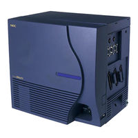
NEC NEC Dterm Series E Installation Manual (410 pages)
Brand:
NEC
| Category:
Test Equipment
| Size: 8 MB
Table of Contents
Liability Disclaimer
3
Table of Contents
17
List of Figures
17
List of Tables
23
Table Title Page
24
Safety Considerations
26
Regulatory Information
27
Regulatory Requirements
27
Fcc Part 15 Requirements
27
Fcc Part 68 Registration
27
Equal Access Requirements
29
Hearing Aid Compatibility
29
Chapter 1 Introduction
31
Figure 1-1 Example of NAP
33
Figure 1-2 Example of a Tree
34
Figure 1-3 Static Caution Indication
35
Figure 1-4 Model 8012 Portable Field Service Kit
35
Chapter 2 Installation Design
37
Environmental Requirements
37
Figure 2-1 Heat Generation from Switching Equipment for the PBX
38
Table 2-1 Temperature and Humidity
38
Floor Space
39
Equipment Room Requirements
39
Power Supply Requirements
40
Figure 2-2 Current Consumption of the PBX
41
Table 2-2 Typical Installation Tools
43
Figure 2-3 System Configuration
44
Table 2-3 Conditions for Configuration
45
Number of Modules
45
Figure 2-4 Time Slot, Group Number Assignment
46
Figure 2-5 Face Layout (Single IMG Configuration)
47
Figure 2-6 Face Layout of IMG0 (Multiple IMG Configuration)
48
Rear View
49
Figure 2-7 Location of Terminating Resistors on the TSWM Back Plane
49
Figure 2-8 Face Layout of IMG1 Front View (Multiple IMG Configuration)
50
Figure 2-9 Face Layout of IMG2, 3 (Multiple IMG Configuration)
51
Figure 2-10 Controlling Circuit Cards in LPM
52
Table 2-4 Controlling Circuit Cards in LPM
52
Figure 2-11 Controlling Circuit Cards in PIM 0 (Single IMG Configuration Only)
53
Table 2-5 Controlling Circuit Cards in PIM 0 (Single IMG Configuration Only)
53
Figure 2-12 Controlling Circuit Cards in PIM
54
Table 2-6 Controlling Circuit Cards in PIM
54
Figure 2-13 Controlling Circuit Cards in TSWM (Multiple IMG Configuration)
55
Table 2-7 Controlling Circuit Cards in TSWM (Multiple IMG Configuration)
55
Installation Cables
56
Specification
57
Figure 2-14 DC Main Power Cable and Main Ground Cable (1- or 2-PIM System) (Single IMG Configuration)
57
Figure 2-15 DC Main Power Cable and Main Ground Cable (3- or 4-PIM System)
58
Figure 2-16 DC Main Power Cable and Main Ground Cable (Multiple IMG Configuration)
59
Table 2-8 Clamp Terminal Shape and Purpose
60
Table 2-9 Selection of T-Type Clamp Terminal
61
Figure 2-17 Calculation Method for Sectional Area
62
Table 2-10 Clamping Tool
62
Table 2-11 Calculation of Number of Cables
63
Figure 2-18 Outline of Cables from Module Group to the Outside
64
Figure 3-1 Scope of Installation Procedure
65
Figure 3-2 Installation Procedure
68
Table 002-1 Specification of Anchor Bolts-Sleeve Expansion Type
71
Figure 002-1 Locations of Base Unit Securing Holes
73
Figure 002-2 Cable Hole on a Free-Access or Computer Floor
74
Figure 002-3 Example of Special Stand
76
Figure 002-4 Special Stand Installation Method
76
Figure 002-5 Example of Elevation
77
Figure 004-1 Mounting the Base Unit on an Ordinary Floor
81
Figure 004-2 Mounting the Base Unit on a Free-Access or Computer Floor
82
Figure 004-3 Mounting the Base Unit on a Free-Access or Computer Floor Via Elevation
82
Figure 004-4 Setting the BASEU Via Special Stand
83
Figure 005-1 Procedure for Mounting Units and Modules
84
Front View
85
Figure 005-2 Locations of FANU
85
Figure 005-3 Mounting of FANU (on TOPU)
86
Figure 005-4 Attachment of FAN Fuse (PZ-M369)
87
Figure 005-5 Cable Connections for FANU on TOPU
88
Figure 005-6 Connection of "FAN" Connector Cable (TOPU-PIM)
89
Figure 005-7 Attachment of the Top Cover
90
Figure 005-8 Relocation of FANU and Insertion into FAN BOX
92
Figure 005-9 FAN Cable Connections for FC0/FC1/FC2 Connectors
93
Figure 005-10 Cable Connections for FANU in FAN BOX
95
Figure 005-11 Connection of "FAN" Connector Cable (FAN BOX-PIM)
96
Figure 005-12 Insertion of NFILU
98
Figure 005-13 Attaching of NFILU
98
Figure 005-14 Cabling Diagram of NFILU
99
Figure 008-1 Detail of Cable Running
103
Figure 008-2 Detail of Cable Running (Multiple IMG Configuration)
104
Figure 008-3 Connection of Power and Ground Cables to Power Receiving Terminal
105
Figure 008-4 Example Connection Diagram-DC-DC Converter for Message Waiting Lamps
107
Figure 008-5 Removal of Shorting Piece and Cable Connection
108
Figure 008-6 Placing the Clamp Terminal on the die
110
Figure 008-7 Clamping Method
110
Figure 008-8 Stripped Length of Main and Branch Cable
112
Table 008-1 Stripped Length
112
Figure 008-9 Inserting of Cables into Terminal
113
Figure 008-10 Clamping for Branch Jointing
113
Figure 008-11 Taping
114
Figure 008-12 Covering
114
Figure 009-1 Removal of Card Stopper
117
Figure 009-2 Extraction of Circuit Cards
120
Figure 009-3 Circuit Card Mounting (Partial Insertion)
120
Figure 009-4 Removal of Front Panel and Top Cover from CPR
121
Figure 009-5 Insertion of ISAGT and LANI Cards into CPR Slots
122
Figure 009-6 Reattachment of CPR Top Cover and Front Panel
123
Figure 009-7 Accommodation of New CPR into LPM
124
Figure 009-8 Insertion of New HFD into CPR
125
Table 010-1 Quick Reference Table (1/6)
127
System Type
127
Frame Name
127
Figure 010-1 Locations of Connectors on the PIM Backplane
133
Figure 010-2 Locations of Connectors on the LPM Backplane
134
Figure 010-3 Location of Connectors on the TSWM Backplane (Multiple IMG Configuration)
135
Rear View
136
Figure 010-4 Locations of Connectors on the Power Distribution Terminal Board (PZ-M371)
136
Figure 010-5 Power Cable Connections for 1-PIM System (Single IMG Configuration)
137
Front View
138
Figure 010-6 Details on Power Cable Connections (for 1-PIM System) (Single IMG Configuration)
138
Table 010-2 Power Cable Connection for IMG0 (Single IMG Configuration)
139
Figure 010-7 Power Cable Connections for 2-PIM System (Single IMG Configuration)
140
Figure 010-8 Details on Power Cable Connections (for 2-PIM System) (Single IMG Configuration)
141
Table 010-3 Power Cable Connections for 2-PIM System (Single IMG Configuration)
142
Figure 010-9 Power Cable Connections for 3-PIM System (Single IMG Configuration)
143
Figure 010-10 Details on Power Cable Connections (for 3-PIM System) (Single IMG Configuration)
144
Table 010-4 Power Cable Connections for 3-PIM System (Single IMG Configuration)
145
Figure 010-11 Power Cable Connections for 4-PIM System (Single IMG Configuration)
146
Figure 010-12 Details on Power Cable Connections (for 4-PIM System) (Single IMG Configuration)
147
Table 010-5 Power Cable Connections for 4-PIM System (Single IMG Configuration)
148
Figure 010-13 Power Cable Connection for IMG0 (Multiple IMG Configuration)
149
Table 010-6 Power Cable Connection for IMG0 (Multiple IMG Configuration)
150
Figure 010-14 Power Cable Connection for IMG1 (1-PIM System) (Multiple IMG Configuration)
151
Table 010-7 Power Cable Connection for IMG1 (1-PIM System) (Multiple IMG Configuration)
152
Figure 010-15 Power Cable Connection for IMG1 (2-PIM System) (Multiple IMG Configuration)
153
Table 010-8 Power Cable Connection for IMG1 (2-PIM System) (Multiple IMG Configuration)
154
Figure 010-16 Power Cable Connection for IMG1 (3-PIM System) (Multiple IMG Configuration)
155
Table 010-9 Power Cable Connection for IMG1 (3-PIM System) (Multiple IMG Configuration)
156
Figure 010-17 Power Cable Connection for IMG1 (4-PIM System) (Multiple IMG Configuration)
157
Table 010-10 Power Cable Connection for IMG1 (4-PIM System) (Multiple IMG Configuration)
158
Figure 010-18 Power Cable Connection for IMG2/3 (1-PIM System) (Multiple IMG Configuration)
159
Table 010-11 Power Cable Connection for IMG2/3 (1-PIM System) (Multiple IMG Configuration)
160
Figure 010-19 Power Cable Connection for IMG2/3 (2-PIM System) (Multiple IMG Configuration)
161
Table 010-12 Power Cable Connection for IMG2/3 (2-PIM System) (Multiple IMG Configuration)
162
Figure 010-20 Power Cable Connection for IMG2/3 (3-PIM System) (Multiple IMG Configuration)
163
Table 010-13 Power Cable Connection for IMG2/3 (3-PIM System) (Multiple IMG Configuration)
164
Figure 010-21 Power Cable Connection for IMG2/3 (4-PIM System) (Multiple IMG Configuration)
165
Table 010-14 Power Cable Connection for IMG2/3 (4-PIM System) (Multiple IMG Configuration)
166
Figure 010-22 Bus Cable Connections for 1-PIM System (Single IMG Configuration)
167
Figure 010-23 Details on Bus Cable Connections (for 1-PIM System) (Single IMG Configuration)
168
Table 010-15 Bus Cable Connections for 1-PIM System (Single IMG Configuration)
169
Figure 010-24 Bus Cable Connections for 2-PIM System (Single IMG Configuration)
170
Figure 010-25 Details on Bus Cable Connections (for 2-PIM System) (Single IMG Configuration)
171
Table 010-16 Bus Cable Connections for 2-PIM System (Single IMG Configuration)
172
Figure 010-26 Bus Cable Connections for 3-PIM System (Single IMG Configuration)
173
Figure 010-27 Details on Bus Cable Connections (for 3-PIM System) (Single IMG Configuration)
174
Table 010-17 Bus Cable Connections for 3-PIM System (Single IMG Configuration)
175
Figure 010-28 Bus Cable Connections for 4-PIM System (Single IMG Configuration)
176
Figure 010-29 Details on Bus Cable Connections (for 4-PIM System) (Single IMG Configuration)
177
Table 010-18 Bus Cable Connections for 4-PIM System (Single IMG Configuration)
178
Figure 010-30 Internal Bus Cable Connection for IMG0 (Multiple IMG Configuration)
179
Table 010-19 Internal Bus Cable Connection for IMG0 (Multiple IMG Configuration)
180
Figure 010-31 Internal Bus Cable Connection for IMG1 (1-PIM System) (Multiple IMG Configuration)
181
Table 010-20 Internal Bus Cable Connection for IMG1 (1-PIM System) (Multiple IMG Configuration)
181
Figure 010-32 Internal Bus Cable Connection for IMG1 (2-PIM System) (Multiple IMG Configuration)
182
Table 010-21 Internal Bus Cable Connection for IMG1 (2-PIM System) (Multiple IMG Configuration)
183
Figure 010-33 Internal Bus Cable Connection for IMG1 (3-PIM System) (Multiple IMG Configuration)
184
Table 010-22 Internal Bus Cable Connection for IMG1 (3-PIM System) (Multiple IMG Configuration)
185
Figure 010-34 Internal Bus Cable Connection for IMG1 (4-PIM System) (Multiple IMG Configuration)
186
Table 010-23 Internal Bus Cable Connection for IMG1 (4-PIM System) (Multiple IMG Configuration)
187
Figure 010-35 Internal Bus Cable Connection for IMG2/3 (2-PIM System) (Multiple IMG Configuration)
188
Figure 010-36 Internal Bus Cable Connection for IMG2/3 (3-PIM System) (Multiple IMG Configuration)
189
Figure 010-37 Internal Bus Cable Connection for IMG2/3 (4-PIM System) (Multiple IMG Configuration)
190
Figure 011-1 Inter-Frame ISA Bus Cable Connection for IMG0-IMG1
192
Table 011-1 Inter-Frame ISA Bus Cable Connection for IMG0-IMG1
192
Figure 011-2 Inter-Frame Bus Cable Connection for IMG0-IMG1
193
Table 011-2 Inter-Frame Bus Cable Connection for IMG0-IMG1
194
Figure 011-3 Inter-Frame Bus Cable Connection for IMG1-IMG2 (1-PIM System)
195
Table 011-3 Inter-Frame Bus Cable Connection for IMG1-IMG2 (1-PIM System)
195
Cable Name
195
Figure 011-4 Inter-Frame Bus Cable Connection for IMG1-IMG2 (2-PIM System)
196
Table 011-4 Inter-Frame Bus Cable Connection for IMG1-IMG2 (2-PIM System)
197
Figure 011-5 Inter-Frame Bus Cable Connection for IMG1-IMG2 (3-PIM System)
198
Table 011-5 Inter-Frame Bus Cable Connection for IMG1-IMG2 (3-PIM System)
199
Figure 011-6 Inter-Frame Bus Cable Connection for IMG1-IMG2 (4-PIM System)
200
Table 011-6 Inter-Frame Bus Cable Connection for IMG1-IMG2 (4-PIM System)
201
Figure 011-7 Inter-Frame Bus Cable Connection for IMG1-IMG3 (1-PIM System)
202
Table 011-7 Inter-Frame Bus Cable Connection for IMG1-IMG3 (1-PIM System)
202
Figure 011-8 Inter-Frame Bus Cable Connection for IMG1-IMG3 (2-PIM System)
203
Table 011-8 Inter-Frame Bus Cable Connection for IMG1-IMG3 (2-PIM System)
204
Figure 011-9 Inter-Frame Bus Cable Connection for IMG1-IMG3 (3-PIM System)
205
Table 011-9 Inter-Frame Bus Cable Connection for IMG1-IMG3 (3-PIM System)
206
Figure 011-10 Inter-Frame Bus Cable Connection for IMG1-IMG3 (4-PIM System)
207
Table 011-10 Inter-Frame Bus Cable Connection for IMG1-IMG3 (4-PIM System)
208
Figure 011-11 Inter-Frame Alarm Bus Cable Connection for IMG0-IMG1
209
Table 011-11 Inter-Frame Alarm Bus Cable Connection for IMG0-IMG1
210
Figure 011-12 Inter-Frame Alarm Bus Cable Connection for IMG0-IMG2
211
Table 011-12 Inter-Frame Alarm Bus Cable Connection for IMG0-IMG2
212
Cable Name
212
Figure 011-13 Inter-Frame Alarm Bus Cable Connection for IMG0-IMG3
213
Figure 012-1 Front Cable Connections between Circuit Cards for CCIS/ISDN
215
Figure 013-1 LT Cable Routing
219
Side View
220
Figure 013-2 Cable Routing of Circuit Card Front Cable
220
Rear Side
223
Figure 013-3 Example of Cable Tying Using Tie-Wrap
223
Figure 013-4 Cable Support Assembly
225
Figure 013-5 Clamp Winding
227
Figure 013-6 Termination of Installation Cables
228
Figure 015-1 Cross Connection of Stations
231
Figure 015-2 Cross Connection of Trunks (C.O. Lines and Tie Lines)
233
Figure 015-3 Mounting Locations of PFT (PA-M53)
234
Figure 015-4 Cross Connection for PFT
236
Figure 015-5 Connection of Alarm Indicating Panel and Music on Hold (Single IMG Configuration)
238
Front View
240
Rear View
240
Figure 015-6 Connection of Alarm Indicating Panel (Multiple IMG Configuration) (1/2)
240
Figure 015-7 Connection of Music on Hold (Multiple IMG Configuration)
241
Figure 015-8 Cable Connection Diagram for TAS (1 of 2)
243
Figure 015-9 Outer View of External Switch
245
Figure 015-10 Connection of External Switches
246
Figure 015-11 Connection of Announcement Machine
248
Figure 015-12 Connection of Paging Equipment
250
Figure 015-13 Outer View of D Term Series E
251
Figure 015-14 Cable Connection for D Term Series E
252
Figure 015-15 PLO Pin Assignments for Receiving Clock (Single IMG Configuration)
254
Figure 015-16 PLO Pin Assignments for Receiving Clock (Multiple IMG Configuration)
255
Figure 015-17 Cable Connection Diagram for Accepting Synchronization Clocks from an External High-Stability Oscillator (Single IMG Configuration)
256
Figure 015-18 Cable Connection Diagram for Accepting Synchronization Clocks from an External High-Stability Oscillator (Multiple IMG Configuration)
257
Figure 015-19 Cable Connection Diagram for Distributing Clock from a Digital Interface
258
Figure 016-1 Outer View of Desk Console
260
Figure 016-2 Cable Connection Diagram for Desk Console (1 of 2)
261
Front View
262
Desk Console
264
Figure 016-3 Cable Connection Diagram (When the Power Is Supplied from the PBX)
264
Figure 016-4 Cable Connection Diagram (When Using Local Power Supply)
266
Figure 016-5 Cable Connection Diagram for DESK CONSOLE Modular Block
267
Figure 016-6 Headset
268
Figure 016-7 Mounting of Handset (Left Side of DESK CONSOLE)
269
Figure 016-8 Mounting of Handset (Right Side of DESK CONSOLE)
272
Figure 016-9 RECC Card Cable Connection Diagram
275
Figure 016-10 Three DESK Consoles and One Recording Equipment
276
Figure 016-11 Six DESK Consoles and One Recording Equipment
277
Figure 016-12 8-Core Line Cable
278
Figure 016-13 Connection of AC-DC Adapter
279
Figure 016-14 Add-On Console Cable Connection Diagram
280
Figure 016-15 Add-On Console Cable Connection Diagram (When Using Local Power Supply)
281
Figure 016-16 Cable Connection Diagram for Add-On Console Modular Block
282
Figure 016-17 Mounting of Add-On Console (Right Side of DESK CONSOLE)
283
Figure 016-18 Mounting of Add-On Console (Left Side of DESK CONSOLE)
285
Figure 016-19 Connection of AC-DC Adapter for Add-On Console
287
Configuration Menu
288
Figure 016-20 Displaying the Configuration Menu
289
Figure 016-21 Selecting a Configuration Item
291
Figure 016-22 Assigning Configuration Data
292
Headset Type
294
Figure 016-23 Updating Configuration Data
301
Figure 017-1 Cabling of MAT When Using Ethernet
303
Figure 017-2 Cable Connection Diagram for the MAT
304
Figure 017-3 Cabling of MAT Using Modems
306
Figure 017-4 Connection of System Message Printer
307
Figure 017-5 Detail of RS-232C CA-(0)
308
Figure 017-6 Detail of RS-232C CA-(1)
309
Figure 017-7 Detail of RS-232C CA-(3)
310
Figure 018-1 I/O Port Interface
311
Front View
312
Figure 018-2 Cable Connection Diagram for the SMDR Equipment
312
Figure 018-3 Connection of SMDR by Using MODEM
313
System Start-Up
315
System Startup Procedure
318
Figure 022-1 LED Indications in Normal Operation (Single IMG Configuration)
330
Figure 022-2 LED Indications of IMG0 in Normal Operation (Multiple IMG Configuration)
331
Front View
332
Figure 022-3 LED Indications of IMG1 in Normal Operation (Multiple IMG Configuration)
332
Figure 022-4 LED Indications of IMG 2/3 in Normal Operation (Example) (Multiple IMG Configuration)
333
Figure 023-1 Alarm Lamps on the TOPU
334
Installation Test Procedure
337
Figure 5-1 Example of Entry to Test Check Column
338
Figure 026-1 How to Perform a Control System Changeover (Single IMG Configuration)
344
Figure 026-2 How to Perform a Control System Changeover (Multiple IMG Configuration)
344
Figure 026-3 Leds and Switches on TSW/MUX
345
Figure 026-4 Leds and Switches for System Changeover (Multiple IMG Configuration)
347
Figure 026-5 System Block Diagram (TSW and MUX) (Multiple IMG Configuration)
348
Figure 026-6 System Block Diagram (GT and Other Controlling Blocks) (Multiple IMG Configuration)
349
Figure 026-7 System Block Diagram (Speech Path) (Multiple IMG Configuration)
350
Figure 027-1 System Initialization Via 'Start' Button
351
Port Connection Test
354
Figure 032-1 COT Test Configuration
360
Figure 032-2 TLT Test Configuration
360
Figure 032-3 DTI Test Configuration
361
Figure 047-1 Combination of Tie Line Network and Public Network
382
Figure 047-2 Tie Line Network
382
Figure 048-1 Test of Tandem Connection to Tie Line
383
Figure 049-1 Example of PAD Setting
385
Figure 049-2 Example of PAD Setting for CCIS
386
Figure 7-1 Mounting of the Covers
396
Figure 7-2 Side Cover Mounting Method (BASEU+LPR+PIM0)
397
Figure 7-3 Side Cover Mounting Method (PIM)
398
Figure 7-4 Rear Cover Mounting Method (BASEU+LPR+PIM0)
399
Figure 7-5 Rear Cover Mounting Method (PIM)
400
Figure 7-6 Rear Cover Mounting Method (FANU)
401
Figure 7-7 Front Cover Mounting Method (BASEU+LPR+PIM0)
402
Figure 7-8 Front Cover Mounting Method (PIM)
403
Figure 7-9 Front Cover Mounting Method (FANU)
404
Figure 7-10 Locations of Inter-Frame Brackets
405
Figure 7-11 How to Attach Inter-Frame Brackets
406
NEC NEC Dterm Series E Manual (45 pages)
Brand:
NEC
| Category:
Telephone
| Size: 1 MB
Table of Contents
Table of Contents
3
Function Keys
4
Programmable Keys
5
Soft Keys (Factory Assigned Features)
6
To Use Soft Keys
7
To Use the HELP Key
8
Lamps
8
Feature Key Activities
9
Terminal Setup with the Feature Key
9
Microphone On/Off
9
To Select Ringer Tone
9
To Adjust Ringer Tone
10
To Preset Ringer Volume
10
To Adjust Transmission/Receiving Volume (During Valid Call)
10
To Originate an Outside Call Via Extension Line Key
11
To Originate an Internal Call
11
Outside Line Appearance
12
To Originate Call Using One-Touch Buttons
12
Automatic Idle Return
13
To Originate a Call Using Speed Calling (Individual Station)
14
Account Code
14
Forced Account Code
15
Authorization Code
15
Voice First/Tone First
15
Originating a Voice Call
16
To Answer a Voice Call Hands Free
16
Automatic Intercom
17
Manual Intercom
17
Dial Intercom
18
To Place a Call on Hold
19
To Place a Call on Exclusive Hold
20
To Transfer a Call
21
Conference
21
To Establish a Broker Call
22
Call Back (Station)
22
To Answer a Camped-On Call
23
To Set Camp-On (Transfer Method)
23
Camp-On (Call Waiting Method)
24
Call Park (System)
25
Call Pick-Up (Group)
26
Call Pick-Up (Direct)
26
Outside Line Queuing (from Extension Dial Tone)
27
Timed Queueing (Outside Line Only)
27
Executive Override
28
Redial (Last Number Redial)
28
Call Forwarding - All Calls
29
Call Forwarding - Busy
30
Call Forwarding - no Answer
31
Call Forwarding - Destination
32
To Save and Repeat a Number
32
Internal Zone Paging with Meet-Me Page
33
Boss/Secretary Calling
34
Boss/Secretary Override
35
Do Not Disturb
36
Timed Reminder
36
Privacy Release
37
Return Message Schedule
38
Name Display
39
Index
40
Quick Reference Guide
42
Product View
43
Advertisement
NEC NEC Dterm Series E User Manual (52 pages)
Agent Console Dterm
Brand:
NEC
| Category:
Telephone
| Size: 1 MB
Table of Contents
Table of Contents
3
Dedicated Function Keys and Lamps
4
Acd Call
5
Call Back
7
To Log on When ID Code Is Required
9
To Log on When ID Code Is Not Required
10
To Log off with or Without ID Codes
11
T O Set Automatic Answer
12
To Set Manual Answer
13
To Answer/Release an Incoming Acd Call
13
To Hold a Call
15
To Transfer a Call to Split Queue
16
To Set/Reset Break Mode
17
Work Mode Duringa Call
19
Tally Count
20
To Place an Assistance Call
20
Monitor Me
21
To Place an Emergency Call
22
To Report Trunk Trouble
23
Tally-Oh Features
23
To Originate an Outside Call
29
To Originate an Internal Call
29
To Originate a Call Using Speed Calling
30
Account Code
31
Forced Account Code
32
Authorization Code
32
Conference
33
To Establisha Broker Call
34
To Answer Acamped-On Call
34
Call Waiting - Originating
35
Call Park
36
Call Pick-Up (Group)
38
Call Pick-Up (Direct)
38
Outgoing Trunk Queuing
39
Off-Hook Trunk Queuing
40
Last Number Redial
40
Call Forwarding - All Calls
41
Call Back
42
To Save and Repeata Number
43
To Leave a Message
44
To Answer a Message
44
Do Not Disturb
45
Privacy
46
Data Features
46
To Establish External Data Transmission Via Modem Pooling
48
NEC NEC Dterm Series E User Manual (14 pages)
NEC D-Term Series E Telephones User Guide
Brand:
NEC
| Category:
Telephone
| Size: 0 MB
Table of Contents
Table of Contents
2
Keys and Lamps
3
Tones
4
Making and Receiving Calls
5
Hold
6
Transfer
7
Conference Calls
7
Soft Keys
8
Feature Keys
9
Speed Dial Keys
9
Pickup
10
Forwarding
10
Voice
10
S&R
11
Call Back
11
Shift
11
Feature
11
Recall
12
Redial
12
Answer
12
Other Features
13
Call Park
13
Directed Call Pickup
13
Headsets
14
Ring Volume
14
Ring Tone
14
LCD Brightness
14
LCD Display
14
NEC NEC Dterm Series E User Manual (9 pages)
MCCCD NEC Dterm Series E TELEPHONE
Brand:
NEC
| Category:
Telephone
| Size: 0 MB
Table of Contents
Telephone Features
6
Conference Calling
6
Hold, Exclusive
7
Speed Dial
7
Call Forward
8
Advertisement
Related Products
NEC Dterm Series i
NEC DTerm E NEAX 2000IVS
NEC DTL-6DE-1
NEC DT400
NEC DTZ-8LD-3
NEC DTZ-12D-3
NEC DT530
NEC UNIVERGE DT920 12D
NEC UNIVERGE DTK-12D-1P
NEC DT710 Series
NEC Categories
Monitor
Projector
Server
Telephone
Computer Hardware
More NEC Manuals
Login
Sign In
OR
Sign in with Facebook
Sign in with Google
Upload manual
Upload from disk
Upload from URL