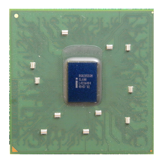
Sign In
Upload
Manuals
Brands
Intel Manuals
Computer Hardware
855GM
Intel 855GM Manuals
Manuals and User Guides for Intel 855GM. We have
1
Intel 855GM manual available for free PDF download: Design Manual
Intel 855GM Design Manual (362 pages)
Chipset Platform
Brand:
Intel
| Category:
Computer Hardware
| Size: 5 MB
Table of Contents
Table of Contents
3
Introduction
21
Table 1. Conventions and Terminology
21
Referenced Documents
23
System Overview
25
Platform Component Features
25
Intel 855GM Platform Component Features
26
Intel Pentium M Processor and Intel Celeron M Processor
26
Figure 1. Intel Pentium M Processor and Intel 855GM Chipset Block Diagram
26
Intel ® 855GM Chipset Graphics Memory Controller Hub (GMCH)
27
Intel Pentium M Processor and Intel Celeron M Processor FSB Support
27
Integrated System Memory DRAM Controller
27
Internal Graphics Controller
27
Package/Power
28
Intel ® 82801DBM I/O Controller Hub 4-Mobile (ICH4-M)
28
Intel ® Pro/Wireless Network Connection
29
Intel 855GME Platform Component Features
30
Intel Pentium ® M Processor on 90 Nm Process with 2 MB L2 Cache
30
Figure 2. Intel Pentium M, Intel Pentium M Processor on 90 Nm Process with 2 MB L2 Cache, Intel Celeron M Processor and 855GME Chipset System Block Diagram
30
Intel 855GME Chipset Graphics Memory Controller Hub (GMCH)
31
Accelerated Graphics Port (AGP) Interface
31
General Design Considerations
33
Nominal Board Stack-Up
33
Alternate Stack Ups
34
Figure 3. Recommended Board Stack-Up Dimensions
34
Intel Pentium M/Celeron M Front Side Bus Design Guidelines
37
Intel Pentium M Processor / Intel Celeron M FSB Design Recommendations
37
Recommended Stack-Up Routing and Spacing Assumptions
37
Trace Space to Trace - Reference Plane Separation Ratio
37
Trace Space to Trace Width Ratio
38
Common Clock Signals
38
Figure 4. Trace Spacing Vs. Trace to Reference Plane Example
38
Figure 5. Three to One Trace Spacing to Trace Width Example
38
Processor Common Clock Signal Package Length Compensation39
39
Table 2. Processor System Bus Common Clock Signal Internal Layer Routing Guidelines
39
Source Synchronous Signals General Routing Guidelines
40
Figure 6. Common Clock Topology
40
Table 3. Processor and GMCH PSB Common Clock Signal Package Lengths and Minimum Board Trace Lengths
40
Figure 7. Layer 6 PSB Source Synchronous Signals GND Referencing to Layer 5
42
Source Synchronous Signal Length Matching Constraints
43
Package Length Compensation
43
Figure 8. Layer 3 PSB Source Synchronous Signals
43
Source Synchronous - Data Group
44
Source Synchronous - Address Group
45
Table 5. Processor System Bus Source Synchronous Data Signal Routing Guidelines
45
Table 6. Processor PSB Address Source Synchronous Signal Trace Length Mismatch Mapping
45
Intel Pentium M / Intel Celeron M Processor and Intel 855GM/GME Chipset GMCH PSB Signal Package Lengths
46
Table 7. Processor PSB Source Synchronous Address Signal Routing Guidelines
46
Table 8. Intel Pentium M / Intel Celeron M Processor and GMCH Source Synchronous FSB Signal Package Lengths
47
Asynchronous Signals
49
Table 9. Asynchronous AGTL+ Nets
49
Topology 1A: Open Drain (OD) Signals Driven by the Processor - IERR
50
Topology 1B: Open Drain (OD) Signals Driven by the Processor - FERR# and THERMTRIP
50
Figure 9. Routing Illustration for Topology 1A
50
Table 10. Layout Recommendations for Topology 1A
50
Topology 1C: Open Drain (OD) Signals Driven by the Processor - PROCHOT
51
Figure 10. Routing Illustration for Topology 1B
51
Table 11. Layout Recommendations for Topology 1B
51
Topology 2A: Open Drain (OD) Signals Driven by ICH4-M - PWRGOOD
52
Figure 11. Routing Illustration for Topology 1C
52
Figure 12. Routing Illustration for Topology 2A
52
Table 12. Layout Recommendations for Topology 1C
52
Topology 2B: CMOS Signals Driven by ICH4-M - DPSLP
53
Topology 2C: CMOS Signals Driven by ICH4-M - LINT0/INTR, LINT1/NMI, A20M#, IGNNE#, SLP#, SMI#, and STPCLK
53
Figure 13. Routing Illustration for Topology 2B
53
Table 13. Layout Recommendations for Topology 2A
53
Table 14. Layout Recommendations for Topology 2B
53
Topology 3: CMOS Signals Driven by ICH4-M to CPU and FWH - INIT
54
Figure 14. Routing Illustration for Topology 2C
54
Figure 15. Routing Illustration for Topology 3
54
Table 15. Layout Recommendations for Topology 2C
54
Voltage Translation Logic
55
Processor RESET# Signal
55
Figure 16. Voltage Translation Circuit
55
Table 16. Layout Recommendations for Topology 3
55
Figure 17. Processor RESET# Signal Routing Topology with no ITP700FLEX Connector
56
Figure 18. Processor RESET# Signal Routing Topology with ITP700FLEX Connector
56
Processor RESET# Routing Example
57
Processor and GMCH Host Clock Signals
57
Figure 19. Processor RESET# Signal Routing Example with ITP700FLEX Debug Port
57
Table 17. Processor RESET# Signal Routing Guidelines with ITP700FLEX Connector
57
Processor GTLREF Layout and Routing Recommendations
58
Figure 20. Processor and GMCH Host Clock Layout Routing Example
58
Figure 21. Processor GTLREF Voltage Divider Network
59
AGTL+ I/O Buffer Compensation
60
Processor AGTL+ I/O Buffer Compensation
60
Figure 22. Processor GTLREF Motherboard Layout
60
Figure 23. Processor COMP[2] & COMP[0] Resistive Compensation
61
Figure 24. Processor COMP[3] & COMP[1] Resistive Compensation
61
Figure 25. Processor COMP[3:0] Resistor Layout
62
Figure 26. Processor COMP[1:0] Resistor Alternative Primary Side Layout
62
Intel Pentium M / Intel Celeron M Front Side Bus Strapping and Debug Port
63
Figure 27. COMP2 & COMP0 27.4-Ω Traces
63
Intel System Validation Debug Support
64
Processor V CCSENSE /V
64
SSSENSE Design Recommendations
64
Figure 28. VCCSENSE /V
64
Table 18. ITP Signal Default Strapping When ITP Debug Port Not Used
64
ITP Support
65
Background/Justification
65
Implementation
65
Intel Pentium M / Intel Celeron M Processor Logic Analyzer Support (FSB LAI)
65
Implementation
66
Intel Pentium M / Intel Celeron M Processor On-Die Logic Analyzer Trigger (ODLAT) Support
66
Onboard Debug Port Routing Guidelines
66
ITP Signal Routing Guidelines
66
Figure 29. ITP700FLEX Debug Port Signals
67
ITP Signal Routing Example
69
Table 19. Recommended ITP700FLEX Signal Terminations
69
ITP_CLK Routing to ITP700FLEX Connector
70
Figure 30. ITP700FLEX Signals Layout Example
71
Figure 31. ITP_CLK to ITP700FLEX Connector Layout Example
71
ITP700FLEX Design Guidelines for Production Systems
72
Recommended ITP Interposer Debug Port Implementation
72
ITP_CLK Routing to ITP Interposer
72
ITP Interposer Design Guidelines for Production Systems
73
Figure 32. ITP_CLK to CPU ITP Interposer Layout Example
73
Logic Analyzer Interface (LAI)
74
Mechanical Considerations
74
Electrical Considerations
74
Intel® Mobile Voltage Positioning IV General Description
75
System Memory Design Guidelines (DDR-SDRAM) for SO-DIMM Configuration
76
Table 20. GMCH Chipset Memory Signal Groups
76
Length Matching and Length Formulas
77
Table 21. Intel 855GM Chipset GMCH DDR 200/266 Length Matching Formulas
77
Table 22. Intel 855GME Chipset GMCH DDR 200/266/333 Length Matching Formulas
77
Package Length Compensation
78
Topologies and Routing Guidelines
78
Clock Signals - SCK[5:0], SCK#[5:0]
78
Clock Topology Diagram
78
Table 23. Clock Signal Mapping
78
Memory Clock Routing Guidelines
79
Figure 33. Memory Clock Routing Topology SCK/SCK#[5:0]
79
Table 24. Clock Signal Group Routing Guidelines
79
Clock Length Matching Requirements
80
Clock Reference Lengths
81
Figure 34. Memory Clock Trace Length Matching Diagram
81
Clock Package Length Table
82
Clock Routing Example
82
Table 25. Memory Clock Package Lengths
82
Data Signals - SDQ[71:0], SDM[8:0], SDQS[8:0]
83
Figure 35. Clock Signal Routing Example
83
Data Bus Topology
84
Figure 36. Data Signal Routing Topology
84
SDQS to Clock Length Matching Requirements
85
Table 26. Memory Data Signal Group Routing Guidelines
85
Data to Strobe Length Matching Requirements
87
Figure 37. SDQS to Clock Trace Length Matching Diagram
87
SDQ to SDQS Mapping
88
Table 27. SDQ/SDM to SDQS Mapping
88
SDQ/SDQS Signal Package Lengths
89
Figure 38. SDQ/SDM to SDQS Trace Length Matching Diagram
89
Table 28. Memory SDQ/SDM/SDQS Package Lengths
89
Memory Data Routing Example
91
Control Signals - SCKE[3:0], SCS#[3:0]
91
Figure 39. Data Signals Group Routing Example
91
Control Signal Topology
92
Figure 40. Control Signal Routing Topology
92
Table 29. Control Signal to SO-DIMM Mapping
92
Control Signal Routing Guidelines
93
Table 30. Control Signal Routing Guidelines
93
Control to Clock Length Matching Requirements
94
Figure 41. Control Signal to Clock Trace Length Matching Diagram
95
Memory Control Routing Example
96
Figure 42. Control Signals Group Routing Example
96
Control Group Package Length Table
97
Command Signals - SMA[12:6,3,0], SBA[1:0], SRAS#, SCAS#, SWE
97
Command Topology 1
97
Table 31. Control Group Package Lengths
97
Command Topology 1 Routing Guidelines
98
Figure 43. Command Routing for Topology 1
98
Table 32. Command Topology 1 Routing Guidelines
98
Command Topology 1 Length Matching Requirements
99
Figure 44. Topology 1 Command Signal to Clock Trace Length Matching Diagram
100
Command Topology 2
101
Figure 45. Command Routing Topology 2
101
Command Topology 2 Routing Guidelines
102
Table 33. Command Topology 2 Routing Guidelines
102
Command Topology 2 Length Matching Requirements
103
Figure 46. Topology 2 Command Signal to Clock Trace Length Matching Diagram
104
Command Topology 2 Routing Example
105
Figure 47. Example of Command Signal Group
105
Command Topology 3
106
Figure 48. Command Routing Topology 3
106
Command Topology 3 Routing Guidelines
107
Table 34. Command Topology 3 Routing Guidelines
107
Command Topology 3 Length Matching Requirements
108
Figure 49. Topology 3 Command Signal to Clock Trace Length Matching Diagram
109
Command Group Package Length Table
110
Table 35. Command Group Package Lengths
110
CPC Signals - SMA[5,4,2,1], SMAB[5,4,2,1]
111
Table 36. CPC Signal to SO-DIMM Mapping
111
CPC Signal Topology
112
CPC Signal Routing Guidelines
112
Figure 50. Command Per Clock Signal Routing Topology
112
Table 37. CPC Signal Routing Guidelines
112
CPC to Clock Length Matching Requirements
113
CPC Group Package Length Table
114
Figure 51. CPC Signals to Clock Length Matching Diagram
114
Table 38. CPC Group Package Lengths
114
Feedback - RCVENOUT#, RCVENIN
115
Routing Updates for "High-Density" Memory Device Support
115
ECC Disable Guidelines
115
GMCH ECC Functionality Disable
115
DDR Memory ECC Functionality Disable
116
System Memory Compensation
116
SMVREF Generation
116
DDR Power Delivery
116
External Thermal Sensor Based Throttling (ETS#)
116
ETS# Usage Model
117
ETS# Design Guidelines
117
Thermal Sensor Routing and Placement Guidelines
117
Figure 52. DDR Memory Thermal Sensor Placement
118
System Memory Design Guidelines (DDR-SDRAM) for Memory down Configuration
120
Figure 53. Recommended Device Order for Micro-DIMM/Memory down Combination
120
Table 39. Supported Memory Configurations - Micro-DIMM
120
Table 40. Supported Memory Configurations - Memory down
121
Table 41. Montara-GM GMCH Chipset DDR Signal Groups
121
Length Matching and Length Formulas
122
Package Length Compensation
122
Table 42. Length Matching Formulas
122
Topologies and Routing Guidelines
123
Clock Signals - SCK[4,3,1,0], SCK#[4,3,1,0]
123
Clock Topology Diagram
123
Figure 54. DDR Clock Routing to Micro-DIMM
123
Table 43. Clock Signal Mapping
123
Figure 55. DDR Clock Routing to Memory down Two Load BGA
124
Figure 56. DDR Clock Routing to Memory down Two Load TSOP
124
Figure 57. DDR Clock Routing to Memory down 4 Load BGA
124
DDR Clock Routing Guidelines
125
Table 44. Clock Signal Group Routing Guidelines
125
Clock Length Matching Requirements
126
Clock Reference Lengths
127
Figure 58. DDR Clock Trace Length Matching Diagram
128
Clock Package Length Table
129
Data Signals - SDQ[63:0], SDM[7:0], SDQS[7:0]
129
Table 45. DDR Clock Package Lengths
129
Data Bus Topology
131
Figure 59. Data Signal Routing GMCH to 1X16 TSOP/BGA & /1X8 BGA Configuration
131
Figure 60. Data Signal Routing GMCH to 2X16 BGA Configuration
131
Table 46. Data Signal Group Routing Guidelines
132
SDQS to Clock Length Matching Requirements
133
Data to Strobe Length Matching Requirements
134
Figure 61. SDQS to Clock Trace Length Matching Diagram
134
SDQ to SDQS Mapping
135
Table 47. SDQ/SDM to SDQS Mapping
135
Figure 62. SDQ/SDM to SDQS Trace Length Matching Diagram
136
SDQ/SDQS Signal Package Lengths
137
Table 48. DDR SDQ/SDM/SDQS Package Lengths
137
Control Signals - SCKE[3:0], SCS#[3:0]
138
Table 49. Control Signal to Micro-DIMM/Memory down Mapping
139
Control Signal Topology
140
Figure 63. Control Signal Routing GMCH to Micro-DIMM Pad
140
Figure 64. Control Signal Routing GMCH to Memory down 1X16 4 Load TSOP
140
Figure 65. Control Signal Routing GMCH to Memory down 1X16/2X16 4 Load BGA
141
Figure 66. Control Signal Routing GMCH to Memory down 1X8 8 Loads BGA
141
Control Signal Routing Guidelines
142
Table 50. Control Signal Routing Guidelines
142
Control to Clock Length Matching Requirements
143
Control Group Package Length Table
144
Figure 67. Control Signal to Clock Trace Length Matching Diagram
144
Table 51. Control Group Package Lengths
144
Command Signals - SMAA[12:6,3,0], SBA[1:0], SRAS#, SCAS#, SWE
145
Command Topology
145
Figure 68. CMD Signal Routing GMCH to Micro-DIMM and Mem down TSOP 4 Load
146
Figure 69. CMD Signal Routing GMCH to Micro-DIMM and Mem down BGA 4 Load
146
Figure 70. CMD Signal Routing GMCH to Micro-DIMM and Memory down BGA 8-Load
147
Command Topology Routing Guidelines
148
Table 52. Command Topology 1 Routing Guidelines
148
Command Topology Length Matching Requirements
149
Figure 71. Topology 1 Command Signal to Clock Trace Length Matching Diagram
150
Command Group Package Length Table
151
Table 53. Command Group Package Lengths
151
CPC Signals - SMA[5,4,2,1], SMAB[5,4,2,1]
152
Table 54. CPC Signal to SO-DIMM Micro-DIMM And/Or Memory down Mapping
152
CPC Signal Topology
153
Figure 72. Command Per Clock Signal Routing Topology 4 Load BGA
153
Figure 73. CPC Signal Routing Topology 4 Load TSOP
153
Figure 74. CPC Signal Routing 8 Load BGA Topology
154
Figure 75. CPC Signal Routing Micro-DIMM
154
CPC Signal Routing Guidelines
155
Table 55. CPC Signal Routing Guidelines
155
CPC to Clock Length Matching Requirements
156
CPC Group Package Length Table
157
Figure 76. CPC Signals to Clock Length Matching Diagram
157
Table 56. CPC Group Package Lengths
157
Integrated Graphics Display Port
159
Analog RGB/CRT Guidelines
159
Ramdac/Display Interface
159
Reference Resistor (REFSET)
159
RAMDAC Board Design Guidelines
160
Figure 77. Refset Placement
160
RAMDAC Routing Guidelines
161
Figure 78. GMCH DAC Routing Guidelines with Docking Connector
161
Table 57. Recommended GMCH DAC Components
162
DAC Power Requirements
163
Figure 79. DAC R, G, B Routing and Resistor Layout Example
163
HSYNC and VSYNC Design Considerations
164
DDC and I2C Design Considerations
164
LVDS Transmitter Interface
164
LVDS Length Matching Constraints
165
LVDS Package Length Compensation
165
LVDS Routing Guidelines
165
Table 58. Signal Group and Signal Pair Names
165
Table 59. LVDS Signal Group Routing Guidelines
166
Table 60. LVDS Package Lengths
167
Digital Video out Port
168
Length Matching Requirements
168
Table 61. DVO Interface Signal Groups
168
Package Length Compensation
169
DVOB and DVOC Routing Guidelines
169
Table 62. DVO Interface Trace Length Mismatch Requirements
169
Table 63. DVOB and DVOC Routing Guideline Summary
170
DVOB and DVOC Assumptions, Definitions, and Specifications
171
Table 64. DVO Interface Package Lengths
171
DVOB and DVOC Simulation Method
172
Figure 80. DVOB and DVOC Simulations Model
172
Figure 81. Driver-Receiver Waveforms Relationship Specification
172
Table 65. Allowable Interconnect Skew Calculation
172
DVOB and DVOC Port Flexible (Modular) Design
173
DVOB and DVOC Module Design
173
Generic Connector Model
173
Figure 82. DVO Enabled Simulation Model
173
Table 66. DVO Enabled Routing Guideline Summary
173
DVO GMBUS and DDC Interface Considerations
174
Figure 83. Generic Module Connector Parasitic Model
174
Table 67. GMBUS Pair Mapping and Options
174
Leaving the GMCH DVOB or DVOC Port Unconnected
175
Miscellaneous Input Signals and Voltage Reference
175
PM_SUS_CLK/AGP_PIPE# Design Consideration
175
Figure 84. GVREF Reference Voltage
176
AGP Port Design Guidelines
177
AGP Interface
177
AGP Interface Signal Groups
177
Table 68. AGP 2.0 Signal Groups
178
Table 69. AGP 2.0 Data/Strobe Associations
178
AGP Routing Guidelines
179
1X Timing Domain Routing Guidelines
179
Trace Length Requirements for AGP 1X
179
Trace Spacing Requirements
179
Trace Length Mismatch
179
Table 70. Layout Routing Guidelines for AGP 1X Signals
179
2X/4X Timing Domain Routing Guidelines
180
Trace Length Requirements for AGP 2X/4X
180
Trace Spacing Requirements
180
Figure 85. AGP Layout Guidelines
180
Trace Length Mismatch Requirements
181
Table 71. Layout Routing Guidelines for AGP 2X/4X Signals
181
Table 72. AGP 2.0 Data Lengths Relative to Strobe Length
181
AGP Clock Skew
182
AGP Signal Noise Decoupling Guidelines
182
Table 73. AGP 2.0 Routing Guideline Summary
182
AGP Interface Package Lengths
183
Table 74. AGP Interface Package Length
183
AGP Routing Ground Reference
184
Pull-Ups
184
Table 75. AGP Pull-Up/Pull-Down Requirements and Straps
185
Table 76. AGP 2.0 Pull-Up Resistor Values
185
AGP VDDQ and VCC
186
VREF Generation for AGP 2.0 (2X and 4X)
186
V AGP Interface (2X/4X)
186
AGP Compensation
186
PM_SUS_CLK/AGP_PIPE# Design Consideration
186
Figure 86. DPMS Circuit
186
Hub Interface
187
Hub Interface Compensation
187
Figure 87. Hub Interface Routing Example
187
Table 77. Hub Interface RCOMP Resistor Values
187
Hub Interface Data HL[10:0] and Strobe Signals
188
HL[10:0] and Strobe Signals Internal Layer Routing
188
Table 78. Hub Interface Signals Internal Layer Routing Summary
188
Table 79. Hub Interface Package Lengths for ICH4-M
189
Table 80. Hub Interface Package Lengths for GMCH
189
Terminating HL[11]
190
Hub VREF/VSWING Generation/Distribution
190
Single Generation Voltage Reference Divider Circuit
190
Table 81. Hub Interface VREF/VSWING Reference Voltage Specifications
190
Locally Generated Voltage Reference Divider Circuit
191
Figure 88. Single VREF/VSWING Voltage Generation Circuit for Hub Interface
191
Table 82. Recommended Resistor Values for Single VREF/VSWING Divider Circuit
191
Single GMCH and ICH4-M Voltage Generation / Separate Divider Circuit for VSWING/VREF
192
Figure 89. ICH4-M and GMCH Locally Generated Reference Voltage Divider Circuit
192
Figure 90. Shared GMCH & ICH4-M Reference Voltage with Separate Voltage Divider Circuit for VSWING and VREF
192
Table 83. Recommended Resistor Values for Separate HIVREF and HI_VSWING Divider
192
Separate GMCH and ICH4-M Voltage Generation / Separate Divider Circuits for VREF and VSWING
193
Hub Interface Decoupling Guidelines
193
Figure 91. Individual HIVREF and HI_VSWING Voltage Reference Divider Circuits for ICH4-M and GMCH
193
Table 84. Recommended Resistor Values for HIVREF and HI_VSWING Divider Circuits for ICH4-M
193
I/O Subsystem
195
IDE Interface
195
Cabling
195
Primary IDE Connector Requirements
196
Figure 92. Connection Requirements for Primary IDE Connector
196
Secondary IDE Connector Requirements
197
Figure 93. Connection Requirements for Secondary IDE Connector
197
Mobile IDE Swap Bay Support
198
ICH4-M IDE Interface Tri-State Feature
198
S5/G3 to S0 Boot up Procedures for IDE Swap Bay
199
Power down Procedures for Mobile Swap Bay
199
Power up Procedures after Device "Hot" Swap Completed
199
Pci
200
Figure 94. PCI Bus Layout Example
200
Figure 95. Intel 82801DBM ICH4-M AC'97 - Codec Connection
201
Figure 96. Intel 82801DBM ICH4-M AC'97 - AC_BIT_CLK Topology
202
Figure 97. Intel 82801DBM AC'97 - AC_SDOUT/AC_SYNC Topology
202
Table 85. AC'97 AC_BIT_CLK Routing Summary
202
Figure 98. Intel 82801DBM AC'97 - AC_SDIN Topology
203
Table 86. AC'97 AC_SDOUT/AC_SYNC Routing Summary
203
Table 87. AC'97 AC_SDIN Routing Summary
203
AC'97 Routing
204
Motherboard Implementation
205
Valid Codec Configurations
205
SPKR Pin Configuration
205
Table 88. Supported Codec Configurations
205
USB 2.0 Guidelines and Recommendations
206
Layout Guidelines
206
General Routing and Placement
206
Figure 99. Example Speaker Circuit
206
USB 2.0 Trace Separation
207
USBRBIAS Connection
207
Figure 100. Recommended USB Trace Spacing
207
USB 2.0 Termination
208
USB 2.0 Trace Length Pair Matching
208
USB 2.0 Trace Length Guidelines
208
Plane Splits, Voids, and Cut-Outs (Anti-Etch)
208
Figure 101. USBRBIAS Connection
208
Table 89. USBRBIAS/USBRBIAS# Routing Summary
208
Table 90. USB 2.0 Trace Length Guidelines (with Common-Mode Choke)
208
VCC Plane Splits, Voids, and Cut-Outs (Anti-Etch)
209
GND Plane Splits, Voids, and Cut-Outs (Anti-Etch)
209
USB Power Line Layout Topology
209
EMI Considerations
210
Common Mode Chokes
210
Figure 102. Good Downstream Power Connection
210
Figure 103. Common Mode Choke Schematic
210
Esd
211
USB Selective Suspend
211
I/O APIC (I/O Advanced Programmable Interrupt Controller)
212
Smbus 2.0/Smlink Interface
212
Figure 104. SMBUS 2.0/Smlink Protocol
213
Smbus Architecture and Design Considerations
214
Smbus Design Considerations
214
General Design Issues/Notes
214
High Power/Low Power Mixed Architecture
214
Figure 105. High Power/Low Power Mixed V
214
Calculating the Physical Segment Pull-Up Resistor
215
Table 91. Bus Capacitance Reference Chart
215
Table 92. Bus Capacitance/Pull-Up Resistor Relationship
215
Fwh
216
FWH Decoupling
216
In Circuit FWH Programming
216
FWH INIT# Voltage Compatibility
216
FWH VPP Design Guidelines
217
FWH INIT# Assertion/Deassertion Timings
217
Figure 106. FWH VPP Isolation Circuitry
217
Rtc
218
Figure 107. RTCX1 and SUSCLK Relationship in ICH4-M
218
Figure 108. External Circuitry for the ICH4-M Where the Internal RTC Is Not Used
218
RTC Crystal
219
Figure 109. External Circuitry for the ICH4-M RTC
219
Table 93. RTC Routing Summary
219
External Capacitors
220
RTC Layout Considerations
221
RTC External Battery Connections
221
RTC External RTCRST# Circuit
222
Figure 110. Diode Circuit to Connect RTC External Battery
222
Figure 111. RTCRST# External Circuit for the ICH4-M RTC
222
Susclk
223
VBIAS DC Voltage and Noise Measurements
223
RTC-Well Input Strap Requirements
223
Internal LAN Layout Guidelines
223
Footprint Compatibility
224
Figure 112. Intel 82801DBM ICH4-M/Platform LAN Connect Section
224
Table 94. LAN Component Connections/Features
224
Intel ® 82801DBM ICH4-M - LAN Connect Interface Guidelines
225
Table 95. LAN Design Guide Section Reference
225
Bus Topologies
226
11.9.2.1.1. LAN on Motherboard Point-To-Point Interconnect
226
Signal Routing and Layout
226
Figure 113. Single Solution Interconnect
226
Table 96. LAN LOM Routing Summary
226
Crosstalk Consideration
227
Impedances
227
Line Termination
227
Terminating Unused LAN Connect Interface Signals
227
Intel 82562ET / Intel 82562 EM Guidelines
227
Figure 114. LAN_CLK Routing Example
227
Guidelines for Intel 82562ET / Intel 82562EM Component
228
Placement
228
Crystals and Oscillators
228
Intel 82562ET / Intel 82562EM Termination Resistors
228
Figure 115. Intel 82562ET / Intel 82562EM Termination
228
Critical Dimensions
229
Distance from Magnetics Module to RJ-45 (Distance A)
229
Figure 116. Critical Dimensions for Component Placement
229
Magnetics Module (Distance B)
230
Reducing Circuit Inductance
230
11.9.3.5.1. Terminating Unused Connections
230
11.9.3.5.2. Termination Plane Capacitance
230
Intel 82562ET/EM Disable Guidelines
231
Figure 117. Termination Plane
231
Figure 118. Intel 82562ET/EM Disable and Power down Circuitry
231
Design and Layout Consideration for Intel 82540EP / 82551QM
232
General Intel 82562ET / 82562EM / 82551QM / 82540EP Differential Pair Trace Routing Considerations
232
Table 97. Intel 82562ET/EM Control Signals
232
Figure 119. Trace Routing
233
11.9.6.1.1. Trace Geometry and Length
234
11.9.6.1.2. Signal Isolation
234
11.9.6.1.3. Magnetics Module General Power and Ground Plane Considerations
234
Figure 120. Ground Plane Separation
235
Common Physical Layout Issues
236
Power Management Interface
237
11.10.1. SYS_RESET# Usage Model
237
11.10.2. PWRBTN# Usage Model
237
11.10.3. Power Well Isolation Control Strap Requirements
237
CPU I/O Signal Considerations
238
Figure 121. ICH4-M CPU I/O Signals with Processor and FWH
238
Platform Clock Routing Guidelines
239
System Clock Groups
239
Table 98. Individual Clock Breakdown
239
Clock Group Topologies and Routing Constraints
240
Figure 122. Clock Distribution Diagram
240
Host Clock Group
241
Figure 123. Source Shunt Termination Topology
241
Table 99. Host Clock Group Routing Constraints
242
Host Clock Group General Routing Guidelines
243
Clock to Clock Length Matching and Compensation
243
Host Clock to CLK66 Routing Recommendations
243
Table 100. Clock Package Length
243
EMI Constraints
244
Figure 124. BCLK to GCLKIN Timing Requirement
244
CLK66 Clock Group
245
Figure 125. CLK66 Clock Group Topology
245
Table 101. CLK66 Clock Group Routing Constraints
246
CLK33 Clock Group
247
Figure 126. CLK33 Group Topology
247
Table 102. CLK33 Clock Group Routing Constraints
247
PCI Clock Group
248
Figure 127. PCI Clock Group Topology
248
Table 103. PCICLK Clock Group Routing Constraints
248
CLK14 Clock Group
249
Figure 128. CLK14 Clock Group Topology
249
Table 104. CLK14 Clock Group Routing Constraints
249
DOTCLK Clock Group
250
Figure 129. DOTCLK Clock Topology
250
Table 105. DOTCLK Clock Routing Constraints
250
SSCCLK Clock Group
251
Figure 130. SSCCLK Clock Topology
251
Table 106. SSCCLK Clock Routing Constraints
251
USBCLK Clock Group
252
Figure 131. USBCLK Clock Topology
252
Table 107. USBCLK Clock Routing Constraints
252
Clock Updates for Intel Pentium M Processor and Intel Celeron M Processor Platforms
253
PWRDWN# Signal Connections
253
Intel 855GM/GME Chipset Based System Power Delivery Guidelines
255
Definitions
255
Platform Power Requirements
255
Table 108. Power Delivery Definitions
255
Platform Power Delivery Architectural Block Diagram
256
Figure 132. Platform Power Delivery Map
256
Voltage Supply
257
Power Management States
257
Power Supply Rail Descriptions
257
Table 109. Power Management States on Intel Reference Board
257
Table 110. Power Supply Rail Descriptions on Intel Reference Board
257
855GM/GME Chipset Based System Power-Up Sequence
258
Processor Power Sequence Requirement
258
GMCH Power Sequencing Requirements
258
ICH4-M Power Sequencing Requirements
259
Figure 133. GMCH Power-Up Sequence
259
Figure 134. ICH4-M Power-Up Sequence
260
1.5 V Power Sequencing
261
Sequencing
261
Table 111. Timing Sequence Parameters ICH4-M
261
Design Guidelines
262
Figure 135. Example V
262
Figure 136. V5REFSUS with +V5ALWAYS Connection Option
262
DDR Memory Power Sequencing Requirements
263
Figure 137. V5REFSUS with +V3ALWAYS and +V5S or +V5 Connection Option
263
Table 112. DDR Power-Up Initialization Sequence
263
Intel 855GM/GME Chipset Based System Power Delivery Guidelines
264
Figure 138. Example for Minimizing Loop Inductance
264
855GM/GME Chipset GMCH Decoupling Guidelines
265
Table 113. GMCH Decoupling Recommendations
265
GMCH VCCSM Decoupling
266
DDR Memory Device VDD Decoupling
266
DDR VTT Decoupling Placement and Layout Guidelines
266
DDR Memory Power Delivery Design Guidelines
266
V Power Delivery Guidelines
267
GMCH and DDR SMVREF Design Recommendations
267
Figure 139. DDR Power Delivery Block Diagram
267
DDR SMRCOMP Resistive Compensation
268
DDR VTT Termination
268
Figure 140. GMCH SMRCOMP Resistive Compensation
268
Figure 141. GMCH System Memory Reference Voltage Generation Circuit
268
DDR SMRCOMP and VTT 1.25-V Supply Disable in S3/Suspend
269
Other GMCH Reference Voltage and Analog Power Delivery
269
Gmch Gtlvref
269
Figure 142. GMCH HDVREF[2:0] Reference Voltage Generation Circuit
269
GMCH AGTL+ I/O Buffer Compensation
270
Figure 143. GMCH HAVREF Reference Voltage Generation Circuit
270
Figure 144. GMCH HCCVREF Reference Voltage Generation Circuit
270
Figure 145. GMCH HXRCOMP and HYRCOMP Resistive Compensation
270
GMCH AGTL+ Reference Voltage
271
GMCH Analog Power
271
Figure 146. GMCH HXSWING and HYSWING Reference Voltage Generation Circuit
271
Figure 147. Example Analog Supply Filter
271
ICH4-M Decoupling / Power Delivery Guidelines
272
ICH4-M Decoupling
272
Table 114. Analog Supply Filter Requirements
272
Hub Interface Decoupling
273
FWH Decoupling
273
General LAN Decoupling
273
Table 115. ICH4-M Decoupling Requirements
273
Intel Pro/Wireless 2100/2100A - Bluetooth Coexistence Interface Design Requirements
275
PCB Interface Requirements
275
DC Power Requirements for Bluetooth
276
Start up Conditions and Logic Protection
276
Figure 148. Recommended Topology for Coexistence Traces
276
USB Selective Suspend
277
Reserved, NC, and Test Signals
279
Intel Pentium M Processor and Intel Celeron M Processor RSVD Signals
279
Processor RSVD Signals
279
Table 116. Processor RSVD and TEST Signal Pin-Map Locations
279
Intel 855GM/GME Chipset GMCH RSVD Signals
280
Table 117. Intel 855GM/GME Chipset GMCH RSVD and NC Signal Pin-Map Locations
280
Platform Design Checklist
281
General Information
281
Customer Implementation of Voltage Rails
282
Design Checklist Implementation
282
Intel Pentium M Processor / Intel Celeron M Processor
284
Resistor Recommendations
284
Figure 149. Routing Illustration for INIT
286
Figure 150. Voltage Translation Circuit for PROCHOT
286
In Target Probe (ITP)
287
Decoupling Recommendations
287
Vccp (I/O)
287
Vcca (Pll)
288
VCC (Core)
288
Clock Checklist
289
Resistor Recommendations
289
Figure 151. Clock Power-Down Implementation
290
Intel 855GM/855GME Checklist
291
System Memory
291
GMCH System Memory Interface
291
DDR SO-DIMM Interface
293
SODIMM Decoupling Recommendation
293
Figure 152. Reference Voltage Level for SMVREF
293
Fsb
294
Figure 153. GMCH HXSWING & HYSWING Reference Voltage Generation Circuit
294
Hub Interface
295
Graphics Interfaces
295
Lvds
295
Dvo
296
Dac
297
Figure 154. DPMS Clock Implementation
297
Miscellaneous
298
GMCH Decoupling Recommendations
299
ICH4-M Checklist
301
PCI Interface and Interrupts
301
Gpio
302
AGP_BUSY# Design Requirement
303
Smbus) System Management Interface
303
AC '97 Interface
304
ICH4-M Power Management Interface
305
FWH/LPC Interface
305
USB Interface
306
Hub Interface
306
Figure 155. Single or Locally Generated GMCH and ICH4-M HIVREF/HI_VSWING Circuit
307
Figure 156. Single Generated GMCH and ICH4-M VSWING/VREF Reference Voltage/ Local Voltage Divider Circuit for VSWING/VREF
307
16.7.10. RTC Circuitry
308
Figure 157. External Circuitry for the RTC
308
16.7.11. LAN Interface
309
16.7.12. Primary IDE Interface
309
16.7.13. Secondary IDE Interface
310
16.7.14. Miscellaneous Signals
310
16.7.15. ICH4-M Decoupling Recommendations
311
USB Power Checklist
311
Downstream Power Connection
311
FWH Checklist
312
Resistor Recommendations
312
Figure 158. Good Downstream Power Connection
312
LAN / Homepna Checklist
313
Resistor Recommendations (for 82562ET / 82562EM)
313
Figure 159. LAN_RST# Design Recommendation
313
16.10.2. Decoupling Recommendations
314
Schematics
315
Advertisement
Advertisement
Related Products
INTEL 852GM -
Intel 855PM
intel 855GME
Intel 852GME
Intel 852PM
Intel 80219
Intel 8XC196Jx
Intel 80C188XL
Intel 80331
Intel 80C188EB
Intel Categories
Motherboard
Computer Hardware
Server
Desktop
Server Board
More Intel Manuals
Login
Sign In
OR
Sign in with Facebook
Sign in with Google
Upload manual
Upload from disk
Upload from URL