Sign In
Upload
Manuals
Brands
Endress+Hauser Manuals
Switch
Liquiphant FTL51B
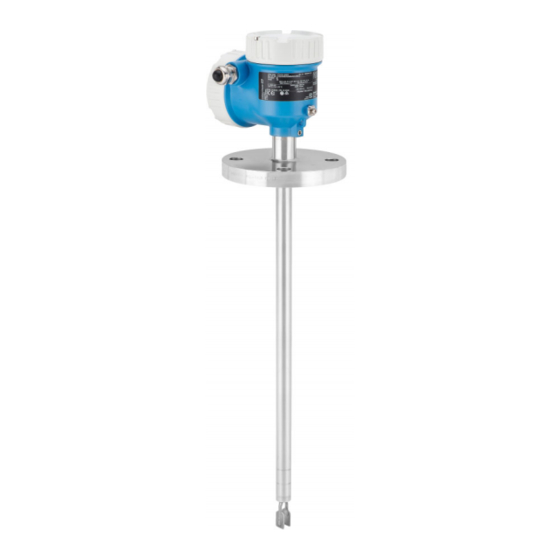
Endress+Hauser Liquiphant FTL51B Manuals
Manuals and User Guides for Endress+Hauser Liquiphant FTL51B. We have
9
Endress+Hauser Liquiphant FTL51B manuals available for free PDF download: Operating Instructions Manual, Brief Operating Instructions, Safety Instruction
Endress+Hauser Liquiphant FTL51B Operating Instructions Manual (64 pages)
Vibronic HART Point level switch for liquids
Brand:
Endress+Hauser
| Category:
Switch
| Size: 1.59 MB
Table of Contents
Table of Contents
3
About this Document
6
Purpose of this Document
6
Symbols
6
Safety Symbols
6
Electrical Symbols
6
Tool Symbols
6
Communication-Specific Symbols
6
Symbols for Certain Types of Information
6
Symbols in Graphics
7
Registered Trademarks
7
Basic Safety Instructions
7
Requirements for the Personnel
7
Intended Use
7
Incorrect Use
8
Workplace Safety
8
Operational Safety
8
Product Safety
8
Functional Safety SIL (Optional)
9
IT Security
9
Device-Specific IT Security
9
Product Description
9
Product Design
10
Incoming Acceptance and Product
10
Identification
10
Incoming Acceptance
10
Product Identification
11
Nameplate
11
Manufacturer Address
11
Storage and Transport
11
Storage Conditions
11
Transporting the Device
11
Mounting
12
Mounting Requirements
12
Take Switch Point into Consideration
12
Take Viscosity into Consideration
13
Avoid Buildup
14
Take Clearance into Consideration
14
Support the Device
14
Weld-In Adapter with Leakage Hole
15
Mounting the Device
15
Required Tool
15
Installation
15
Sliding Sleeves
18
Post-Mounting Check
18
Electrical Connection
18
Required Tool
18
Connecting Requirements
19
Cover with Securing Screw
19
Potential Equalization
19
Connecting the Device
20
Supply Voltage
20
Terminals
20
Cable Specification
20
4-20 Ma HART
21
Overvoltage Protection
21
Wiring
22
Terminal Assignment
22
Cable Entries
23
Available Device Plugs
23
Ensuring the Degree of Protection
24
Degree of Protection
24
Post-Connection Check
24
Operation Options
25
Overview of Operating Options
25
To 20 Ma HART (FEL60H) Electronic Insert
25
Function Test Using Operating Key on Electronic Insert
26
Structure and Function of the Operating Menu
27
User Roles and Related Access Authorization
27
Access to the Operating Menu Via the Local Display
27
Device Display (Optional)
27
Operation Via Bluetooth® Wireless Technology (Optional)
28
Access to the Operating Menu Via the Operating Tool
29
Historom Data Management
29
System Integration
29
Overview of Device Description Files
29
Measured Variables Via HART Protocol
29
Device Variables and Measured Values
30
System Units
30
Commissioning
30
Preliminaries
30
As-Delivered State
31
Function Check
31
Switching on the Device
31
Establishing a Connection Via Fieldcare and Devicecare
31
Via HART Protocol
31
Fieldcare/Devicecare Via Service Interface (CDI)
32
Configuring the Device Address Via Software
32
Setting the Operating Language
32
Local Display
32
Fieldcare
32
Devicecare
32
Device Configuration
33
Commissioning with DIP Switch and Operating Keys on the Electronic Insert
33
Resetting the Password or Device Via Operating Keys
34
Commissioning with "Commissioning" Wizard
34
Storing the Oscillation Frequencies
34
Simulation
34
Protecting Settings from Unauthorized Access
35
Locking or Unlocking the Hardware
35
Locking or Unlocking the Display Operation
35
Parameter Configuration - Locking or Enabling
35
Operation
36
Reading off the Device Locking Status
36
Reading off Measured Values
36
Adapting the Device to Process Conditions
36
Level Limit Detection
36
Sensor Frequency
37
Heartbeat Technology (Optional)
37
Heartbeat Verification
37
Heartbeat Verification/Monitoring
37
Proof Testing for SIL/WHG Devices (Optional)
38
Diagnostics and Troubleshooting
38
General Troubleshooting
38
General Errors
38
Error - Smartblue Operation with Bluetooth
39
Additional Tests
40
Behavior of Current Output in the Event of a Fault
40
Diagnostic Information on Local Display
40
Diagnostic Message
40
Diagnostic Event in the Operating Tool
42
Adapting the Diagnostic Information
42
Queued Diagnostic Messages
42
Diagnostic List
42
Event Logbook
44
Event History
44
Filtering the Event Logbook
45
Overview of Information Events
45
Resetting the Device
46
Resetting the Device Via the Operating Software or Display
46
Resetting the Device Via Operating Keys on the Electronic Insert
46
Device Information
46
11.10 Firmware History
47
11.10.1 Version 01.00.Zz
47
Maintenance
47
Maintenance Tasks
47
Cleaning
47
Repair
47
General Notes
47
Repair Concept
47
Repair of Ex-Certified Devices
48
Spare Parts
48
Replacement
48
Historom
48
Return
48
Disposal
49
Accessories
49
Device Viewer
49
Weather Protection Cover for Dual Compartment Housing
49
Weather Protection Cover for Single Compartment Housing, Aluminum
49
Plug-In Jack
50
Sliding Sleeves for Unpressurized Operation
51
High Pressure Sliding Sleeves
51
Technical Data
53
Input
53
Measured Variable
53
Measuring Range
53
Output
53
Output Signal
53
Signal on Alarm
53
Load
54
Damping
54
Switch Output
54
Ex Connection Data
54
Protocol-Specific Data
55
Wireless HART Data
55
Heartbeat Technology
56
Environment
56
Ambient Temperature Range
56
Storage Temperature
57
Humidity
57
Operating Height
57
Climate Class
57
Degree of Protection
57
Vibration Resistance
57
Shock Resistance
57
Mechanical Load
57
15.3.10 Pollution Degree
58
Electromagnetic Compatibility
58
(Emc)
58
Process
58
Process Temperature Range
58
Thermal Shock
58
Process Pressure Range
58
Overpressure Limit
59
State of Aggregation
59
Medium Density
59
Viscosity
59
Pressure Tightness
60
Solids Contents
60
Additional Technical Data
60
Index
61
Advertisement
Endress+Hauser Liquiphant FTL51B Operating Instructions Manual (64 pages)
Vibronic Point level switch for all kinds of liquids
Brand:
Endress+Hauser
| Category:
Switch
| Size: 1.9 MB
Table of Contents
Table of Contents
3
About this Document
5
Symbols Used
5
Safety Symbols
5
Electrical Symbols
5
Communication Specific Symbols
5
Symbols for Certain Types of Information
5
Symbols in Graphics
6
Basic Safety Instructions
7
Requirements for the Personnel
7
Designated Use
7
Incorrect Use
7
Workplace Safety
7
Operational Safety
7
Product Safety
8
Security
8
Product Description
9
Product Design
9
Incoming Acceptance and Product
10
Identification
10
Incoming Acceptance
10
Product Identification
10
Nameplate
10
Manufacturer Address
10
Storage and Transport
11
Storage Conditions
11
Handling of the Device
11
Installation
12
Installation Conditions
12
Switch Point
12
Take Viscosity into Consideration
12
Avoid Buildup
13
Take Clearance into Consideration
14
Support the Device
14
Leakage Hole
14
Mounting the Measuring Device
15
Required Tools
15
Installation
15
Sliding Sleeves
17
Post-Installation Check
17
Electrical Connection
18
Connection Conditions
18
PE Connection
19
Connecting the Measuring Device
19
2-Wire AC (Electronic Insert FEL61)
19
3-Wire DC-PNP (Electronic Insert FEL62)
22
Universal Current Connection with Relay Output (Electronic Insert FEL64)
24
DC Connection, Relay Output (Electronic Insert FEL64 DC)
26
PFM Output (Electronic Insert FEL67)
28
2-Wire NAMUR > 2.2 Ma/< 1.0 Ma (Electronic Insert FEL68)
31
2-Wire Density (Electronic Insert FEL60D) for Density Measurement
32
LED Module
35
Bluetooth Module
35
Relay Output
36
Cable Entry
36
Special Connection Instructions
36
Hardware Settings
36
Ensuring the Degree of Protection
36
Post-Connection Check
36
Operation Options
37
Overview of Operation Options
37
Operating Concept
37
Operation at Electronic Insert
37
Diagnostics and Verification with Bluetooth® Wireless Technology
40
LED Module (Optional)
40
LED Indicator
41
Commissioning
41
Function Check
41
Switching on the Measuring Device
41
Configuring the Measuring Device
41
Smartblue (App)
41
Advanced Settings
42
Configuration Management
42
Simulation
42
Functional Test of the Electronic Switch with a Test Magnet
42
Functional Test Using the Button on the Electronic Insert
43
Protecting Settings from Unauthorized Access
44
Bluetooth Parameters for Heartbeat
44
Verification Wizard for Proof Testing
44
Operation
45
Overview of the Diagnostics Menu
45
Diagnostics and Troubleshooting
46
General Troubleshooting
46
Diagnostic Information Via Light Emitting
46
Diodes
46
Diagnostic Information on Local Display
47
Diagnostic Information Via the Communication Interface
47
Adapting the Diagnostic Information
47
Overview of Diagnostic Information
47
Pending Diagnostic Messages
47
Diagnostic List
47
Event Logbook
47
10.10 Resetting the Measuring Device
47
10.11 Device Information
47
10.12 Firmware History
47
Maintenance
48
Maintenance Tasks
48
Cleaning
48
Repair
49
General Information
49
Repair Concept
49
Repair of Ex-Certified Devices
49
Spare Parts
49
Return
49
Disposal
49
Accessories
50
Device-Specific Accessories
50
Test Magnet
50
Weather Protection Cover for Single-Compartment Housing
50
Weather Protection Cover for Dual-Compartment Housing
50
M12 Connecting Cable
51
Bluetooth Module
51
LED Module
51
Sliding Sleeves for Unpressurized Operation
51
High Pressure Sliding Sleeves
52
Communication-Specific Accessories
53
Service-Specific Accessories
53
System Components
53
Technical Data
54
Input
54
Measured Variable
54
Measuring Range
54
Density
54
Type of Input
54
Output
54
Output and Input Variants
54
Output Signal
55
Signal on Alarm
56
Ex Connection Data
56
Environment
56
Ambient Temperature Range
56
Storage Temperature
57
Humidity
57
Operating Altitude
57
Climate Class
57
Degree of Protection
57
Vibration Resistance
58
Shock Resistance
58
14.3.10 Mechanical Load
58
14.3.11 Electromagnetic Compatibility
58
Process
58
Process Temperature Range
58
Thermal Shock
58
Process Pressure Range
59
Test Pressure
59
Density of the Process Medium
60
Pressure Tightness
60
Additional Technical Data
60
Index
61
Endress+Hauser Liquiphant FTL51B Operating Instructions Manual (64 pages)
Point level switch for liquids
Brand:
Endress+Hauser
| Category:
Switch
| Size: 1.96 MB
Table of Contents
Table of Contents
3
About this Document
5
Purpose of this Document
5
Symbols
5
Safety Symbols
5
Electrical Symbols
5
Tool Symbols
5
Symbols for Certain Types of Information
5
Symbols in Graphics
6
Registered Trademarks
6
Basic Safety Instructions
6
Requirements for the Personnel
6
Intended Use
6
Incorrect Use
6
Workplace Safety
7
Operational Safety
7
Product Safety
7
Functional Safety SIL (Optional)
7
IT Security
8
Product Description
8
Product Design
8
Incoming Acceptance and Product
9
Identification
9
Incoming Acceptance
9
Product Identification
9
Nameplate
9
Electronic Insert
9
Manufacturer Address
9
Storage and Transport
9
Storage Conditions
9
Transporting the Device
10
Mounting
10
Mounting Requirements
11
Take Switch Point into Consideration
11
Take Viscosity into Consideration
11
Avoid Buildup
12
Take Clearance into Consideration
12
Support the Device
13
Weld-In Adapter with Leakage Hole
13
Mounting the Device
14
Required Tool
14
Installation
14
Sliding Sleeves
15
Post-Mounting Check
16
Electrical Connection
16
Required Tool
16
Connecting Requirements
16
Cover with Securing Screw
16
Connecting Protective Earth (PE)
16
Connecting the Device
17
2-Wire AC (Electronic Insert FEL61)
17
3-Wire DC-PNP (Electronic Insert FEL62)
19
Universal Current Connection with Relay Output (Electronic Insert FEL64)
22
DC Connection, Relay Output (Electronic Insert FEL64 DC)
24
PFM Output (Electronic Insert FEL67)
26
2-Wire NAMUR > 2.2 Ma/ < 1.0 Ma (Electronic Insert FEL68)
28
LED Module VU120 (Optional)
30
Bluetooth Module VU121 (Optional)
32
Connecting the Cables
33
Post-Connection Check
34
Operation Options
35
Overview of Operation Options
35
Operating Concept
35
Elements on the Electronic Insert
35
Heartbeat Diagnostics and Verification with Bluetooth® Wireless Technology
35
LED Module VU120 (Optional)
36
Commissioning
36
Function Check
36
Functional Test Using Key on Electronic Insert
36
FEL61 Switching Behavior and Signaling
37
FEL62 Switching Behavior and Signaling
38
FEL64, FEL64DC Switching Behavior and Signaling
38
FEL67 Switching Behavior and Signaling
38
FEL68 Switching Behavior and Signaling
40
Functional Test of the Electronic Switch with a Test Magnet
40
Switching on the Device
40
Establishing a Connection Via Smartblue App
41
Prerequisites
41
Preparatory Steps
41
Smartblue App
41
Operation
43
"Diagnostics" Menu
43
Application" Menu
43
System" Menu
44
Heartbeat Verification
45
Proof Testing for SIL/WHG Devices
45
Diagnostics and Troubleshooting
46
Diagnostic Information Via Light Emitting
46
Diodes
46
LED at Electronic Insert
46
Smartblue
46
Firmware History
47
Maintenance
47
Maintenance Tasks
47
Cleaning
47
Repair
47
General Notes
47
Repair Concept
47
Repair of Ex-Certified Devices
48
Spare Parts
48
Return
48
Disposal
48
Battery Disposal
48
Accessories
49
Device Viewer
49
Test Magnet
49
Weather Protection Cover for Dual Compartment Housing, Aluminum
49
Protective Cover for Single Compartment Housing, Aluminum or 316L
50
Plug-In Jack
50
Bluetooth Module VU121 (Optional)
51
LED Module VU120 (Optional)
51
Sliding Sleeves for Unpressurized Operation
52
High Pressure Sliding Sleeves
53
Technical Data
55
Input
55
Measured Variable
55
Measuring Range
55
Output
55
Output and Input Variants
55
Output Signal
56
Ex Connection Data
56
Environment
56
Ambient Temperature Range
56
Storage Temperature
57
Humidity
57
Operating Altitude
57
Climate Class
58
Degree of Protection
58
Vibration Resistance
58
Shock Resistance
58
Mechanical Load
58
14.3.10 Pollution Degree
58
14.3.11 Electromagnetic Compatibility
58
Process
58
Process Temperature Range
58
Thermal Shock
59
Process Pressure Range
59
Overpressure Limit
60
Density
60
Viscosity
60
Pressure Tightness
60
Solids Contents
60
Additional Technical Data
60
Index
61
Advertisement
Endress+Hauser Liquiphant FTL51B Operating Instructions Manual (60 pages)
Vibronic Limit switch for liquids
Brand:
Endress+Hauser
| Category:
Switch
| Size: 1.69 MB
Table of Contents
Table of Contents
3
1 About this Document
5
Symbols
5
Safety Symbols
5
Electrical Symbols
5
Symbols for Certain Types of Information
5
Symbols in Graphics
5
2 Basic Safety Instructions
6
Requirements for the Personnel
6
Designated Use
6
Incorrect Use
6
Workplace Safety
6
Operational Safety
6
Product Safety
7
IT Security
7
3 Product Description
7
Product Design
8
4 Incoming Acceptance and Product
9
Incoming Acceptance and Product
9
Identification
9
Incoming Acceptance
9
Product Identification
9
Nameplate
9
Manufacturer Address
9
Storage and Transport
10
Storage Conditions
10
Transporting the Device
10
5 Installation
11
Mounting Conditions
11
Taking the Switch Point into Consideration
11
Take Viscosity into Consideration
12
Avoiding Buildup
13
Take Clearance into Consideration
13
Support the Device
14
Weld-In Adapter with Leakage Hole
14
Mounting the Measuring Device
14
Required Tools
14
Installation
15
Sliding Sleeves
16
Post-Installation Check
16
6 Electrical Connection
17
Connection Conditions
17
Cover with Securing Screw
17
Connecting Protective Earth (PE)
17
Connecting the Measuring Device
17
2-Wire AC (Electronic Insert FEL61)
17
3-Wire DC-PNP (Electronic Insert FEL62)
19
Universal Current Connection with Relay Output (Electronic Insert FEL64)
21
DC Connection, Relay Output (Electronic Insert FEL64 DC)
23
PFM Output (Electronic Insert FEL67)
25
2-Wire NAMUR > 2.2 Ma/< 1.0 Ma (Electronic Insert FEL68)
27
Bluetooth Module VU121 (Optional)
29
LED Module VU120 (Optional)
30
Cable Entry
30
Post-Connection Check
31
7 Operation Options
32
Overview of Operation Options
32
Operating Concept
32
Functional Test Using the Button on the Electronic Insert
32
Functional Test of the Electronic Switch with a Test Magnet
35
Heartbeat Diagnostics and Verification with Bluetooth® Wireless Technology
36
LED Module VU120 (Optional)
37
Configuration and Sensor Status
37
8 Commissioning
37
Function Check
37
Switching on the Measuring Device
38
Establishing a Connection Via Smartblue (App)
38
Smartblue (App)
38
9 Operation
40
"Diagnostics" Menu
40
Application" Menu
40
System" Menu
41
Heartbeat Verification
42
Recurrent Testing for SIL/WHG (German Water Resources Act) Devices
42
10 Diagnostics and Troubleshooting
42
Diagnostic Information Via Light Emitting
43
Diodes
43
LED at Electronic Insert
43
Smartblue
43
11 Maintenance
44
Maintenance Tasks
44
Cleaning
44
12 Repair
45
General Information
45
Repair Concept
45
Repair of Ex-Certified Devices
45
Spare Parts
45
Return
45
Disposal
46
13 Accessories
47
Device-Specific Accessories
47
Test Magnet
47
Weather Protection Cover for Dual-Compartment Housing, Aluminum
47
Weather Protection Cover for Single-Compartment Housing, Metal
47
Plug-In Jack
48
Additional Modules
48
Sliding Sleeves for Unpressurized Operation
49
High Pressure Sliding Sleeves
50
14 Technical Data
52
Input
52
Measured Variable
52
Measuring Range
52
Output
52
Output and Input Variants
52
Output Signal
53
Ex Connection Data
53
Environment
53
Ambient Temperature Range
53
Storage Temperature
54
Humidity
54
Operating Altitude
55
Climate Class
55
Degree of Protection
55
Vibration Resistance
55
Shock Resistance
55
Mechanical Load
56
14.3.10 Electromagnetic Compatibility
56
Process
56
Process Temperature Range
56
Thermal Shock
56
Process Pressure Range
56
Test Pressure
57
Density
57
Pressure Tightness
58
Additional Technical Data
58
Index
59
Endress+Hauser Liquiphant FTL51B Operating Instructions Manual (36 pages)
Vibronic Density measurement for liquids
Brand:
Endress+Hauser
| Category:
Measuring Instruments
| Size: 1.01 MB
Table of Contents
Table of Contents
3
About this Document
5
Purpose of this Document
5
Symbols
5
Safety Symbols
5
Electrical Symbols
5
Tool Symbols
5
Symbols for Certain Types of Information
5
Symbols in Graphics
6
Documentation
6
Standard Documentation
6
Supplementary Device-Dependent Documentation
6
Basic Safety Instructions
6
Requirements for the Personnel
6
Intended Use
7
Incorrect Use
7
Workplace Safety
7
Operational Safety
7
Product Safety
8
IT Security
8
Product Description
8
Product Design
9
Incoming Acceptance and Product
9
Identification
9
Incoming Acceptance
9
Product Identification
10
Nameplate
10
Manufacturer Address
10
Storage and Transport
10
Storage Conditions
10
Mounting
11
Mounting Requirements
11
Flow Velocity - Installation in Piping
12
Inlet and Outlet Runs
12
Correction Factor
13
Avoid Buildup
16
Take Clearance into Consideration
16
Support the Device
16
Weld-In Adapter with Leakage Hole
17
Mounting the Device
17
Required Tool
17
Installation
18
Sliding Sleeves
20
Post-Mounting Check
20
Electrical Connection
20
Required Tool
20
Connecting Requirements
20
Cover with Securing Screw
20
Connecting Protective Earth (PE)
21
Connecting the Device
21
2-Wire Density (Electronic Insert FEL60D) for Density Measurement
21
Connecting the Cables
23
Post-Connection Check
24
Operation Options
25
Overview of Operation Options
25
Operating Concept
25
Elements on the Electronic Insert
25
Commissioning
25
Function Check
25
Switching on the Device
25
Operation
26
Light Signals
26
Diagnostics and Troubleshooting
26
Diagnostic Information Via Light Emitting
26
Diodes
26
LED at Electronic Insert
26
Firmware History
27
Maintenance
27
Maintenance Tasks
27
Cleaning
27
Repair
27
General Notes
27
Repair Concept
27
Repairs to Ex-Approved Devices
27
Spare Parts
28
Return
28
Disposal
28
Accessories for Liquiphant Density
28
Protective Cover for Aluminum Dual Compartment Housing
28
Protective Cover for Single Compartment Housing, Aluminum or 316L
29
M12 Socket
29
Weld-In Adapter
30
Accessories for Density Computer
30
Fml621
30
General
30
Extension Cards
31
PROFINET® Interface
31
Technical Data
31
Input
31
Measured Variable
31
Measuring Range
32
Output
32
Output and Input Variants
32
Ex Connection Data
32
Environment
32
Ambient Temperature Range
32
Storage Temperature
32
Operating Altitude
32
Climate Class
32
Degree of Protection
32
Pollution Degree
33
Process
33
Process Temperature Range
33
Thermal Shock
33
Process Pressure Range
33
Pressure Tightness
33
Additional Technical Data
34
Index
35
Endress+Hauser Liquiphant FTL51B Brief Operating Instructions (40 pages)
Vibronic Point level switch for liquids
Brand:
Endress+Hauser
| Category:
Switch
| Size: 1.43 MB
Table of Contents
1 About this Document
3
Table of Contents
3
Symbols
3
2 Basic Safety Instructions
5
Designated Use
5
Operational Safety
5
Requirements for the Personnel
5
Workplace Safety
5
Incoming Acceptance
6
3 Incoming Acceptance and Product Identification
6
IT Security
6
Product Safety
6
Product Identification
7
Storage and Transport
7
4 Mounting
8
Mounting Conditions
9
Mounting the Measuring Device
13
Post-Installation Check
15
Sliding Sleeves
15
Connecting the Measuring Device
16
Connection Conditions
16
5 Electrical Connection
16
Post-Connection Check
35
6 Operation Options
36
Overview of Operation Options
36
7 Commissioning
38
Function Check
38
LED Module VU120 (Optional)
38
Establishing a Connection Via Smartblue (App)
39
Further Information
39
Switching on the Measuring Device
39
Endress+Hauser Liquiphant FTL51B Brief Operating Instructions (29 pages)
Brand:
Endress+Hauser
| Category:
Switch
| Size: 1.06 MB
Table of Contents
Related Documents
2
About this Document
3
Basic Safety Instructions
4
Requirements for the Personnel
4
Intended Use
4
Workplace Safety
5
Operational Safety
5
Incoming Acceptance and Product Identification
6
Storage and Transport
7
Mounting Requirements
8
Mounting the Device
13
Electrical Connection
16
Connecting the Device
17
Ensuring the Degree of Protection
22
Operation Options
23
Overview of Operating Options
24
Switching on the Device
26
Further Information
26
Endress+Hauser Liquiphant FTL51B Safety Instruction (24 pages)
Brand:
Endress+Hauser
| Category:
Measuring Instruments
| Size: 0.5 MB
Table of Contents
Table of Contents
3
Associated Documentation
4
Supplementary Documentation
4
General Notes: Combined Approval
4
Certificates and Declarations
4
Certificate Holder
5
Other Standards
5
Extended Order Code
5
Safety Instructions: General
10
Safety Instructions: Special Conditions
10
Safety Instructions: Installation
12
Safety Instructions: Zone 0
14
Safety Instructions: Zone Separation Zone 0, Zone 1
14
Temperature Tables
15
Connection Data
22
Endress+Hauser Liquiphant FTL51B Safety Instruction (20 pages)
Brand:
Endress+Hauser
| Category:
Laboratory Equipment
| Size: 0.45 MB
Table of Contents
Table of Contents
3
Associated Documentation
4
Supplementary Documentation
4
General Notes: Combined Approval
4
Manufacturer's Certificates
4
Manufacturer Address
5
Other Standards
5
Extended Order Code
5
Safety Instructions: General
8
Safety Instructions: Special Conditions
8
Safety Instructions: Installation
9
Safety Instructions: Zone 0
12
Safety Instructions: Zone Separation Zone 0, Zone 1
12
Temperature Tables
12
Connection Data
15
Advertisement
Related Products
Endress+Hauser Liquiphant FTL31
Endress+Hauser Liquiphant FTL33 IO-Link
Endress+Hauser nivotester FTL 325 P
Endress+Hauser nivotester FTL 375 P-1 Series
Endress+Hauser Nivotester FTL 375 N 3 Series
Endress+Hauser Nivotester FTL325N-1 1
Endress+Hauser Liquiphant T FTL20H
Endress+Hauser Liquiphant FTL41
Endress+Hauser Nivotester FTL325N-3 3 Series
Endress+Hauser FTE30
Endress+Hauser Categories
Measuring Instruments
Transmitter
Radar
Switch
Accessories
More Endress+Hauser Manuals
Login
Sign In
OR
Sign in with Facebook
Sign in with Google
Upload manual
Upload from disk
Upload from URL