ADTRAN Total Access 300 Series Systems Manuals
Manuals and User Guides for ADTRAN Total Access 300 Series Systems. We have 12 ADTRAN Total Access 300 Series Systems manuals available for free PDF download: Installation And Maintenance Manual, Instruction Manual, Manual, Quick Start Manual
ADTRAN Total Access 300 Series Installation And Maintenance Manual (138 pages)
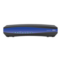
Single Family Unit ONT
Brand: ADTRAN
|
Category: Network Hardware
|
Size: 6 MB
Table of Contents
Advertisement

ADTRAN Total Access 300 Series Installation And Maintenance Manual (102 pages)
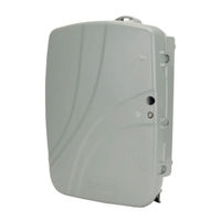
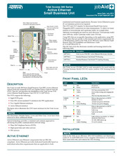
Active Ethernet Single Family Unit ONT
Brand: ADTRAN
|
Category: Network Hardware
|
Size: 4 MB
Table of Contents
ADTRAN Total Access 300 Series Installation And Maintenance Manual (72 pages)
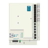
Small Business Unit ONT
Brand: ADTRAN
|
Category: Network Hardware
|
Size: 3 MB
Table of Contents
Advertisement

ADTRAN Total Access 300 Series Installation And Maintenance Manual (70 pages)
GigE SFU ONT with RF Overlay and SWRD Powering
Brand: ADTRAN
|
Category: Control Systems
|
Size: 3 MB
Table of Contents
ADTRAN Total Access 300 Series Installation And Maintenance Manual (62 pages)
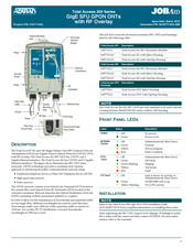
GigE SFU ONT with RF Overlay
Brand: ADTRAN
|
Category: Network Hardware
|
Size: 2 MB
Table of Contents

ADTRAN Total Access 300 Series Installation And Maintenance Manual (60 pages)
Brand: ADTRAN
|
Category: Network Hardware
|
Size: 2 MB
Table of Contents

ADTRAN Total Access 300 Series Manual (4 pages)
Single Family Unit ONT
Brand: ADTRAN
|
Category: Network Hardware
|
Size: 1 MB
Table of Contents

ADTRAN Total Access 300 Series Instruction Manual (4 pages)
Active Ethernet Single Family Unit ONT
Brand: ADTRAN
|
Category: Network Hardware
|
Size: 1 MB
Table of Contents
ADTRAN Total Access 300 Series Installation And Maintenance Manual (4 pages)
Brand: ADTRAN
|
Category: Control Unit
|
Size: 0 MB
Table of Contents
ADTRAN Total Access 300 Series Manual (4 pages)
Brand: ADTRAN
|
Category: Control Unit
|
Size: 0 MB
Table of Contents

ADTRAN Total Access 300 Series Manual (4 pages)
Brand: ADTRAN
|
Category: Control Unit
|
Size: 0 MB
Table of Contents

ADTRAN Total Access 300 Series Quick Start Manual (4 pages)
Brand: ADTRAN
|
Category: Network Hardware
|
Size: 1 MB
Advertisement