ADTRAN Total Access 300 Series Installation And Maintenance Manual
Small business unit ont
Hide thumbs
Also See for Total Access 300 Series:
- Installation and maintenance manual (138 pages) ,
- Quick start manual (4 pages) ,
- Instruction manual (4 pages)

Related Manuals for ADTRAN Total Access 300 Series


Summary of Contents for ADTRAN Total Access 300 Series
- Page 1 Total Access 300 Series Small Business Unit ONT Installation and Maintenance Guide Document Number: 612877SBONT-5B March 2014...
- Page 2 In no event will ADTRAN be liable for any special, incidental, or consequential damages or for commercial losses even if ADTRAN has been advised thereof as a result of issue of this document.
- Page 3 This document has been created to combine the Installation, Troubleshooting and Mainte- nance information for the Total Access 300 Series Small Business Unit ONTs in one document. Revision B was created to add the Common Language Equipment Identification (CLEI) codes to the respective ONTs.
- Page 4 Total Access 300 Series Small Business Unit ONT Installation and Maintenance Guide Hazard Classifications The following hazard classifications are used in this document: DANGER DANGER indicates a hazard with a high level of risk which, if not avoided, will result in death or serious injury.
- Page 5 Training ADTRAN offers training courses on our products. These courses include overviews on product features and functions while covering applications of ADTRAN product lines. ADTRAN provides a variety of training options, including customized training and courses taught at our facilities or at customer sites.
- Page 6 Total Access 300 Series Small Business Unit ONT Installation and Maintenance Guide 612877SBONT-5B...
-
Page 7: Table Of Contents
Total Access 300 Series ONT ........ - Page 8 Total Access 300 Series Small Business Unit ONT Installation and Maintenance Guide Section 2 Small Business Unit Installation....... . 2-1 Scope of this Section .
- Page 9 ADTRAN Technical Support........
- Page 10 Total Access 300 Series Small Business Unit ONT Installation and Maintenance Guide 612877SBONT-5B...
- Page 11 Figures Figures Figure 1-1. Total Access 372 ONT ......... . 1-4 Figure 1-2.
- Page 12 Total Access 300 Series Small Business Unit ONT Installation and Maintenance Guide Tables Table Intro-1. Topic List ..........Intro-1 Table Intro-2.
-
Page 13: Introduction
Introduction Introduction Scope of this Guide This document provides instructions for the installation and maintenance of the Total Access 300 Series Small Business Unit ONT, including LED descriptions, regulatory information, and troubleshooting procedures. In this Guide This guide contains the topics listed in Table Intro-1. -
Page 14: Related Documentation
Total Access 300 Series Small Business Unit ONT Installation and Maintenance Guide Related Documentation Refer to Table Intro-2 for additional information for this product. Documentation for ADTRAN Carrier Networks products is available for viewing and download directly from the ADTRAN Support Community website. -
Page 15: Small Business Unit Ont
Section 1, Small Business Unit ONT Small Business Unit ONT Scope of this Section This section provides information on each of the Total Access 300 Series Small Business Unit ONTs in this manual. In this Section This guide contains the topics listed in Table 1-1. -
Page 16: Gpon Technology
Total Access 300 Series Small Business Unit ONT Installation and Maintenance Guide GPON Technology GPON technology provides a consistent and common approach to advancing the public communications network using: • Traditional telephone services [Plain Old Telephone Service (POTS)] • High speed data services •... -
Page 17: Total Access 300 Series Ont
Section 1, Small Business Unit ONT - Total Access 300 Series ONT Total Access 300 Series ONT The Total Access 300 Series of Small Business Unit ONTs consists of the ADTRAN ONT electronic modules and housings listed in Table 1-2. -
Page 18: Total Access 372
Total Access 300 Series Small Business Unit ONT Installation and Maintenance Guide Total Access 372 ® 372 Small Business Unit (SBU) Optical Network Termination (ONT) The Total Access (P/N 1287722G1) provides telephone and Internet access for a small business. -
Page 19: Total Access 372R With Rf Overlay
Section 1, Small Business Unit ONT - Total Access 300 Series ONT Total Access 372R with RF Overlay ® 372R Small Business Unit (SBU) Optical Network Termination (ONT) The Total Access (P/N 1287722G2) provides telephone, Internet access and an RF Overlay coaxial interface. -
Page 20: Safety And Regulatory Compliance
Risk of Electrical Shock • The Coaxial output of the Total Access 300 Series Single Family Unit ONT is intended to be connected to the dwelling coaxial distribution system. Verify the coaxial distribution system is separately grounded. Grounding... - Page 21 2. This device must accept any interference received, including interference that may cause undesired operation. Changes or modifications not expressly approved by ADTRAN could void the user’s authority to operate this equipment. The equipment meets the EU’s RoHS Directive 2002/95/EC and/or applicable exemptions.
-
Page 22: Components And Interfaces
• Circuit Board Mechanical Components The ONT is designed for outdoor or indoor applications. The ADTRAN Model 774 or 775 outdoor Network Interface Device (NID) housing is intended as a demarcation point between the Telco and a subscriber premises for outdoor application. For indoor application, neither of these housings are used. -
Page 23: Outer Enclosure With Cover Removed
Section 1, Small Business Unit ONT - Components and Interfaces Outer Enclosure with Cover Removed The Outer Enclosure base (refer to Figure 1-3) contains cable entry points for power, ground, Telco incoming cabling and cabling to the customer premises. Each cable entry has grommets to provide environmental protection. -
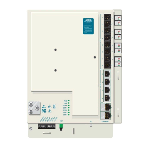
Page 24: Electronics Module
Total Access 300 Series Small Business Unit ONT Installation and Maintenance Guide Electronics Module The Electronics Module (see Figure 1-4) is not designed to be removed after the initial instal- lation. Security Cover Figure 1-4. Total Access 372R Electronics Module... -
Page 25: Circuit Board
Section 1, Small Business Unit ONT - Components and Interfaces Circuit Board WARNING Do Not open the Electronics Module or attempt to remove the Circuit Board from the Electronics Module. The ONT contains a single circuit board contained within the Electronics Module that provides the following functions: •... -
Page 26: Alarm Reporting
Total Access 300 Series Small Business Unit ONT Installation and Maintenance Guide Alarm Reporting The circuit board provides alarm reporting for the Uninterruptible Power Supply (UPS). The following alarms are supported: • Low Battery • Battery Missing • Replace Battery •... -
Page 27: Rf Interface
Section 1, Small Business Unit ONT - Components and Interfaces RF Interface The ONT includes an analog video transmitter that provides a CATV interface over a standard F-Type connector. The RF interface capabilities are listed below: • Frequency Range of 54 - 1000 MHz •... - Page 28 Total Access 300 Series Small Business Unit ONT Installation and Maintenance Guide 1-14 612877SBONT-5B...
-
Page 29: Small Business Unit Installation
Section 2 Section 2, Small Business Unit Installation Small Business Unit Installation Scope of this Section This section provides Installation information for the Small Business Unit (SBU) ONTs listed Table 2-1. Table 2-1. Small Business Unit ONT Title Part Number Total Access 372 Small Business Unit ONT 1287722G1 Total Access 372R Small Business Unit with RF Overlay ONT... -
Page 30: Installation
3. Examine the power supply to ensure that the UPS, battery and power cord are present and sound. If damage has occurred, file a claim with the carrier then contact ADTRAN Customer Service. Refer to Appendix A, “Warranty and Customer Support”... -
Page 31: Required Tools
Section 2, Small Business Unit Installation - Installation Required Tools Standard technician tools are used for an ONT installation (for example, drill, drill bits, side cutters, screwdrivers, nut drivers, hex wrenches, wire strippers, etc.). Specifically, the following tools are required for the installation of the ONT: •... -
Page 32: Instructions For Installing The Sbu Ont
Total Access 300 Series Small Business Unit ONT Installation and Maintenance Guide Instructions for Installing the SBU ONT A typical exterior ONT installation with UPS is shown in Figure 2-1. Customer provided premises wiring including CAT5 or higher Ethernet cable and POTS... -
Page 33: Determining Ont Enclosure Location
Section 2, Small Business Unit Installation - Installation CAUTION • This equipment must be connected to a known, reliable earth ground at all times during installation and service. Refer to the National Electrical Code (NEC) and state/local codes for details on grounding requirements. A minimum 6 AWG copper ground conductor shall be used to connect the equipment to earth ground. - Page 34 Total Access 300 Series Small Business Unit ONT Installation and Maintenance Guide into the ONT interfaces from the old NID ground or arcing connections of the old wiring when lightning strikes occur. • Never allow the ONT customer interfaces to be spliced to a primary station protector or OSP wiring.
-
Page 35: Mounting The Enclosure Outdoors
Section 2, Small Business Unit Installation - Installation Mounting the Enclosure Outdoors Use a maximum of 1/4 inch diameter lag bolts to fit properly in the diameter of the mounting holes (see Figure 2-2). Make sure to leave a minimum clearance of 2 inches (5.1 cm) from the hinges for opening the door. -
Page 36: Install The Electronics Module
Total Access 300 Series Small Business Unit ONT Installation and Maintenance Guide Install the Electronics Module Refer to Figure 2-3 when installing the Electronics Module in the Enclosure: 1. Align the slots on the reverse of the Electronics Module with the tabs on the Enclosure. -
Page 37: Completed Outdoor Sbu Ont Installation
Section 2, Small Business Unit Installation - Installation Completed Outdoor SBU ONT Installation Figure 2-4 displays the various wire routing and drops when the Electronics Module is completely configured and installed in the Enclosure. Note: Safety Cover has been removed for illustration purposes. Note: The RJ-11 POTS ports are used for test purposes only. -
Page 38: Ground Wire Connection
Total Access 300 Series Small Business Unit ONT Installation and Maintenance Guide Ground Wire Connection WARNING Take extreme care when attaching the ground connectors to the utility (earth) ground rod. If the ground is interrupted or disturbed in any way, an unsafe condition will exist. -
Page 39: Figure 2-6. Ont Ground Connection
Section 2, Small Business Unit Installation - Installation 7. Ensure the ground wire is routed as shown in Figure 2-6. TOTAL ACCESS 372 1287722G1 TELEPHONE TROUBLESHOOTING: 1. Identify the bad line (POTS 1-8). 2. Plug any working phone into the appropriate jack. If the telephone works, the unit is functioning normally. -
Page 40: Alternative Grounding Method
PVC conduit (or method used by your local telephone com- pany). For power, ADTRAN recommends using 16 AWG wire at a maximum of 100 feet (30.5 meters). For alarm signals, ADTRAN recommends using 24 AWG wire. Do not plug in the UPS green connector at this time. -
Page 41: Ont Power Connector
Section 2, Small Business Unit Installation - Installation ONT Power Connector The ONT is provided with a 7-pin Power/Alarm connector located at the base of the Electronics Module. Figure 2-7 is an example of the connector. This connector is part of the circuit board and is not intended to be removed. -
Page 42: Figure 2-8. Power/Alarm Connector
Total Access 300 Series Small Business Unit ONT Installation and Maintenance Guide TOTAL ACCESS 372 1287722G1 TELEPHONE TROUBLESHOOTING: 1. Identify the bad line (POTS 1-8). 2. Plug any working phone into the appropriate jack. If the telephone works, the unit is functioning normally. -
Page 43: Installation Of The Power Supply
Section 2, Small Business Unit Installation - Installation Installation of the Power Supply WARNING • Before making any power connections to this equipment, verify the power is off (fuse removed/breaker tripped). • This equipment should only be operated from the type of certified/listed power supply supplied by the manufacturer with the equipment. -
Page 44: Table 2-4. Ups Pin-Out Connection
Total Access 300 Series Small Business Unit ONT Installation and Maintenance Guide CAUTION Connecting the UPS incorrectly can cause damage to the unit. Use caution when connecting the wiring. Table 2-4. UPS Pin-Out Connection Pin-Out Pin-Out Description Power/Alarm LOW BAT... -
Page 45: Subscriber Connections
Section 2, Small Business Unit Installation - Installation Subscriber Connections Refer to Figure 2-11 Figure 2-12 on page 2-19 to install subscriber POTS, Ethernet and DS1 services. Fiber Tray Installation To install the Fiber Tray, refer to Figure 2-11 and complete the following steps: 1. -
Page 46: Pots Connections
Total Access 300 Series Small Business Unit ONT Installation and Maintenance Guide POTS Connections To connect POTS, refer to Figure 2-11 to complete the following steps: 1. Trim each wire to length. Identify each pair in the service cable. 2. Remove the rubber grommet from the housing and insert the POTS cables through the grommet. -
Page 47: Install Ethernet Connections
Section 2, Small Business Unit Installation - Installation Install Ethernet Connections The ONT supports two Gigabit Ethernet ports. The cable used should be rated CAT-5 or 6. For Ethernet connections refer to Figure 2-12 Table 2-5 to complete the following steps: 1. -
Page 48: Table 2-5. Ethernet Cable Pin-Outs
Total Access 300 Series Small Business Unit ONT Installation and Maintenance Guide Table 2-5. Ethernet Cable Pin-Outs Ethernet RJ-45 Pin-out Name Description Color Code TRD0+ Transmit/Receive Positive White/Orange TRD0- Transmit/Receive Negative Orange TRD1+ Transmit/Receive Positive White/Green TRD2+ Transmit/Receive Positive Blue... -
Page 49: Install Ds1 Connections
Section 2, Small Business Unit Installation - Installation Install DS1 Connections For the DS1 Connections, refer to Figure 2-12 on page 2-19 and Table 2-7 to complete the following steps: 1. Route the wires through the same cable entry as the POTS cables. 2. -
Page 50: Install Fiber To The Unit
Total Access 300 Series Small Business Unit ONT Installation and Maintenance Guide Install Fiber to the Unit CAUTION Ensure that fiber used is UL Listed Optical Fiber Cable suitable for this application, and does not contain any metallic members or other electrical conductive materials. -
Page 51: Install Rf Overlay
Section 2, Small Business Unit Installation - Installation NOTE Refer to Figure 2-4 on page 2-9 for an illustration of a completed installation. Install RF Overlay To install RF Overlay to the ONT, refer to Figure 2-14 and complete the following steps: 1. -
Page 52: Optitap Installation
Total Access 300 Series Small Business Unit ONT Installation and Maintenance Guide OptiTap Installation CAUTION Ensure that fiber used is UL Listed Optical Fiber Cable suitable for this application, and does not contain any metallic members or other electrical conductive materials. -
Page 53: Figure 2-16. Optitap Installation
Section 2, Small Business Unit Installation - Installation 8. Clean all optical surfaces before and after splicing. 9. Splice the incoming fiber to the Optical Fiber of the OptiTap Connector using a Fiber Optical Fusion Splice Tool. 10. Using the Fiber Jumper (P/N 1062737145), connect one end to the Optitap Connector and the other to the Optical Connection on the bottom of the Electronics Module. -
Page 54: Mounting The Electronics Module Indoors
Total Access 300 Series Small Business Unit ONT Installation and Maintenance Guide Mounting the Electronics Module Indoors NOTE The Electronics Module must be installed in a Restricted Access location. To install the Electronics Module indoors, refer to Figure 2-17 and the following instructions: 1. -
Page 55: Installed Indoor Electronics Module
Section 2, Small Business Unit Installation - Installation Installed Indoor Electronics Module All installation procedures are the same for the Indoor unit as they are for the Outdoor unit. However, because the housing is not being utilized for indoor applications, wires and cables are routed and secured differently. -
Page 56: Figure 2-19. Optitap Routing
Total Access 300 Series Small Business Unit ONT Installation and Maintenance Guide TOTAL ACCESS 372 1287722G1 TELEPHONE TROUBLESHOOTING: 1. Identify the bad line (POTS 1-8). 2. Plug any working phone into the appropriate jack. If the telephone works, the unit is functioning normally. -
Page 57: Commissioning And Testing
Section 2, Small Business Unit Installation - Commissioning and Testing Commissioning and Testing This section provides detailed information on the following: • “Turn-Up” below • Depending on the local service provider’s requirements the technician may be required to perform additional tests beyond the ONT on the Customer Provided Equipment (CPE) wiring and/or equipment. -
Page 58: Front Panel Leds
Total Access 300 Series Small Business Unit ONT Installation and Maintenance Guide Front Panel LEDs The ONT provides front panel LEDs to display status information. The ONT LEDs and status descriptions are shown in Table 2-8. Table 2-8. Front Panel LEDs... -
Page 59: Test For Pots Line Faults
Section 2, Small Business Unit Installation - Commissioning and Testing Test for POTS Line Faults Look at the “TELEPHONE TROUBLESHOOTING” instructions on the Security Cover of the Electronics Module for directions in determining line faults. NOTE If the problem is still not corrected, it is possible there is an internal wiring problem with the premises. - Page 60 Total Access 300 Series Small Business Unit ONT Installation and Maintenance Guide 2-32 612877SBONT-5B...
-
Page 61: Troubleshooting
Section 3, Troubleshooting Troubleshooting Scope of this Section This section presents Troubleshooting information for the Total Access 300 Series Single Family Unit ONT. Maintenance and ONT Specification information is also provided. The ONTs covered in this section are listed in “Specifications”... -
Page 62: Troubleshooting
Total Access 300 Series Small Business Unit ONT Installation and Maintenance Guide Troubleshooting When troubleshooting a ONT unit, consider the following two principles: • Because voice and data signals originate at the OLT equipment, a failure of all services normally indicates the problem is before the ONT. A failure at the OLT equipment normally results in a loss of service to multiple customers. -
Page 63: Leds In Fault State
Section 3, Troubleshooting - Troubleshooting If the above tests are successful, the indication of the trouble is directed back toward the CPE wiring/equipment. LEDs in Fault State Descriptions of each LED are listed in “Front Panel LEDs” on page 2-30 in Section 2 with possible causes for fault LED conditions. -
Page 64: Figure 3-1. Network Led Flowchart
Total Access 300 Series Small Business Unit ONT Installation and Maintenance Guide NET LED RED Check reflective Is there Work with power with Optical a failure at OLT admin power meter the OLT? to resolve Is power Replace ONT NET LED solid green... -
Page 65: Pots Troubleshooting
Section 3, Troubleshooting - Troubleshooting POTS Troubleshooting When the POTS LED is red, the port is in a fault condition. To correct the problem, do the following: • Contact the OLT administrator and ensure the port is provisioned and working. If the port is provisioned and working, proceed to the next step. -
Page 66: Signal Level Verification
Total Access 300 Series Small Business Unit ONT Installation and Maintenance Guide Signal Level Verification The following sections detail signal level verification if problems are encountered when service activation of an installed ONT is performed. Both “Downstream Signal Level Verifi- cation”... -
Page 67: Upstream Signal Level Verification
Section 3, Troubleshooting - Troubleshooting • If the measurement results are within range, perform the steps in “Upstream Signal Level Verification” below. Upstream Signal Level Verification A valid optical power level delivered by the ONT must be received by the OLT in burst mode at 1310 nm that is controlled in the upstream direction by grants given by the OLT. -
Page 68: Ups Communication Signals
Maintenance The ONT does not require routine maintenance for normal operation. Do not attempt to repair the ONT in the field. Repair services are obtained by returning the defective unit to ADTRAN. Refer to Appendix A, “Warranty and Customer Support”... -
Page 69: Specifications
Section 3, Troubleshooting - Specifications Specifications Specifications for the ONT are detailed in Table 3-6. Table 3-6. Specifications Specification Description Power Voltage Range: 12 VDC (nominal), 10.8 VDC to 14.4 VDC (tolerance) Maximum Current: 2.0 Amp Environmental Operating Temperature: –40°F to 149°F (–40°C to +65°C) Storage Temperature: –40°F to 185°F (–40°C to +85°C) Relative Humidity:... - Page 70 Total Access 300 Series Small Business Unit ONT Installation and Maintenance Guide 3-10 612877SBONT-5B...
-
Page 71: Warranty And Customer Support
Appendix A Warranty and Customer Support Warranty ADTRAN will replace or repair our products within the warranty period if they do not meet their published specifications or fail while in service. Warranty information can be found at www.adtran.com/warranty. ADTRAN Customer Care From within the U.S.: 1.800.726.8663... - Page 72 Carrier Networks Division 901 Explorer Blvd. Huntsville, AL 35806 U.S.A. http://www.adtran.com ADTRAN CUSTOMER CARE From within the U.S. 1.800.726.8663 From outside the U.S. +1 256.963.8716 PRICING AND AVAILABILITY 1.800.827.0807...
Need help?
Do you have a question about the Total Access 300 Series and is the answer not in the manual?
Questions and answers