ADTRAN Total Access 300 Series Installation And Maintenance Manual
Single family unit ont
Hide thumbs
Also See for Total Access 300 Series:
- Installation and maintenance manual (102 pages) ,
- Quick start manual (4 pages) ,
- Instruction manual (4 pages)

Subscribe to Our Youtube Channel
Related Manuals for ADTRAN Total Access 300 Series


Summary of Contents for ADTRAN Total Access 300 Series
- Page 1 Total Access 300 Series Single Family Unit ONT Installation and Maintenance Guide Document Number: 612877GONT-5C April 2019...
- Page 2 In no event will ADTRAN be liable for any special, incidental, or consequential damages or for commercial losses even if ADTRAN has been advised thereof as a result of issue of this document.
- Page 3 Ethernet/1 RF Overlay Outdoor SFU ONT April 2019 Updated fiber routing for the 1187770G1 Revision Functional Description This document has been created to combine the Installation, Troubleshooting, and Mainte- nance for the Total Access 300 Series Single Family Unit ONTs in one document. 612877GONT-5C...
- Page 4 Total Access 300 Series Single Family Unit ONT Installation and Maintenance Guide Hazard Classifications The following hazard classifications are used in this document: DANGER DANGER indicates a hazard with a high level of risk which, if not avoided, will result in death or serious injury.
- Page 5 Icons Icons The following icons are used throughout the ADTRAN document suite: application guide deployment guide diagnostic guide engineering guide installation guide jobAid manual reference guide release notes safety and regulatory upgrade guide user guide 612877GONT-5C...
- Page 6 Total Access 300 Series Single Family Unit ONT Installation and Maintenance Guide 612877GONT-5C...
-
Page 7: Table Of Contents
Total Access 300 Series ONT ........ - Page 8 Total Access 300 Series Single Family Unit ONT Installation and Maintenance Guide Total Access 300 Series Housings and Bracket ..... 1-15 Section 2 Single Family Unit Indoor Installation .
- Page 9 Electronics Module ..........3-8 Circuit Board.
- Page 10 Total Access 300 Series Single Family Unit ONT Installation and Maintenance Guide Scope of this Section ..........4-1 In this Section.
- Page 11 Section 6 Troubleshooting ..........6-1 Scope of this Section .
- Page 12 ONT OptiTap Housing ......... . 3-7 Figure 3-5. Total Access 300 Series Electronics Module ......3-8 Figure 3-6.
- Page 13 Figure 4-1. Electronics Module and Bracket ........4-2 Figure 4-2.
- Page 14 Total Access 300 Series Single Family Unit ONT Installation and Maintenance Guide Tables Table Intro-1. Topic List ..........Intro-1 Table Intro-2.
-
Page 15: Introduction
Indoor, Unrestricted Access Location. Section 6 Troubleshooting This section covers Troubleshooting for all the Total Access 300 Series ONTs. Specifications for all ONTs is also included in this section. Appendix A Warranty and Customer Support This section contains information regarding Warranty and Customer Service information. -
Page 16: Related Online Documents And Resources
Total Access 300 Series Single Family Unit ONT Installation and Maintenance Guide Related Online Documents and Resources Refer to Table Intro-2 for additional information for this product. Documentation for ADTRAN Carrier Networks products is available for viewing and download directly from the ADTRAN Support Community website. - Page 17 Table Intro-2. Related Online Documents and Resources (Continued) Title Part Number Description Total Access 362R 2 POTS/2 Ethernet/1 61287715G1-17 This document provides Safety and RF SFU ONT Safety and Regulatory Regulatory Compliance Notice infor- Compliance Notice mation for the Total Access 362R ONT.
- Page 18 Total Access 300 Series Single Family Unit ONT Installation and Maintenance Guide Table Intro-2. Related Online Documents and Resources (Continued) Title Part Number Description Total Access 5000 System-level Documentation Total Access 5000 Series Fiber to the 65K95FTTP-50 Provides the minimum configuration...
-
Page 19: Single Family Unit Ont
Section 1, Single Family Unit ONT Single Family Unit ONT Scope of this Section This section provides information on each of the Total Access 300 Series ONTs in this manual. In this Section This guide contains the topics listed in Table 1-1. - Page 20 Total Access 300 Series Single Family Unit ONT Installation and Maintenance Guide on splitting optical wavelengths to end points along the way. These passive components, such as splitters and coupler devices, work by passing or restricting light and do not require power to transmit data.
-
Page 21: Total Access 300 Series Ont
Total Access 300 Series ONT Table 1-2 provides a list of each ONT covered in this manual. Each link provides basic infor- mation related to that ONT. Table 1-2. ONTs Topic See Page “Total Access 324 Single Family Unit ONT”... -
Page 22: Total Access 324 Single Family Unit Ont
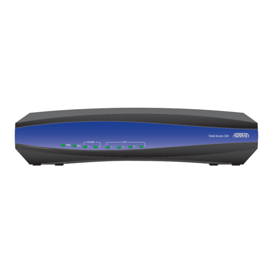
Total Access 300 Series Single Family Unit ONT Installation and Maintenance Guide Total Access 324 Single Family Unit ONT ® The Total Access 324 Single Family Unit (SFU) ONT (P/N 1287735G1) provides telephone and Internet access for a single subscriber residence. -
Page 23: Total Access 324 Single Family Unit Ont With Ups
Total Access 324 Single Family Unit ONT with UPS ® The Total Access 324 Single Family Unit (SFU) ONT with UPS (P/N 1287735G2) provides telephone and Internet access for a single subscriber residence. The ONT has 2 POTS interfaces and support for up to four 1-Gigabit interfaces. Figure 1-2 illustrates the Front and Back of ONT. -
Page 24: Total Access 334 3Rd Generation Single Family Unit Ont With Rf Overlay
Total Access 300 Series Single Family Unit ONT Installation and Maintenance Guide Total Access 334 3rd Generation Single Family Unit ONT with RF Overlay ® The Total Access 334 3rd Generation Single Family Unit (SFU) with RF Overlay (P/N 1287736G3) provides telephone, Internet, and video access for a single subscriber residence. -
Page 25: Total Access 351 Single Family Unit Ont
Total Access 351 Single Family Unit ONT ® The Total Access 351 Single Family Unit (SFU, P/N 1287701G1) is a Gigabit Ethernet ONT that supports the following interfaces: ■ Two POTS Ports ■ One Gigabit Ethernet interface Figure 1-4 illustrates the Total Access 351 Electronics Module. TIP/RING POWER POTS 1... -
Page 26: Total Access 352 Single Family Unit Ont
Total Access 300 Series Single Family Unit ONT Installation and Maintenance Guide Total Access 352 Single Family Unit ONT ® The Total Access 352 Single Family Unit (SFU, P/N 1287702G1 and 1287702G1C) is a Gigabit Ethernet ONT that supports the following interfaces: ■... -
Page 27: Total Access 352H 2Nd Generation Single Family Unit Ont
Total Access 352H 2nd Generation Single Family Unit ONT ® The Total Access 352H 2nd Generation Single Family Unit (SFU, P/N 1287702G3) is a Gigabit Ethernet ONT that supports the following interfaces: ■ Two POTS Ports ■ Two Gigabit Ethernet interfaces ■... -
Page 28: Hpna
Total Access 300 Series Single Family Unit ONT Installation and Maintenance Guide HPNA The ONT has one HPNA coaxial interface. HPNA is an alliance of leading technology companies that promote the adoption of a high performance existing-wire home networking standard for applications such as triple-play service. HPNA features guaranteed QOS, and remote management and diagnostics. -
Page 29: Total Access 361 Single Family Unit Ont
Total Access 361 Single Family Unit ONT The Total Access® 361 Single Family Unit ONT (P/N 1287711G1) is a GPON ONT with RF that supports the following interfaces: ■ Two POTS Ports ■ One Gigabit Ethernet interfaces ■ One RF Video Overlay coaxial interface Figure 1-7 illustrates the ONT Electronics Module. -
Page 30: Total Access 362 Single Family Unit Ont
Total Access 300 Series Single Family Unit ONT Installation and Maintenance Guide Total Access 362 Single Family Unit ONT The Total Access® 362 Single Family Unit ONT (P/N 1287712G1) is a GPON ONT with RF that supports the following interfaces: ■... -
Page 31: Total Access 362R Single Family Unit Ont
Total Access 362R Single Family Unit ONT The Total Access® 362R Single Family Unit (P/N 1287715G1) is a GPON ONT with a CATV RF that supports the following interfaces: ■ Two POTS Ports ■ Two Gigabit Ethernet interfaces ■ One CATV RF coaxial interface Figure 1-9 illustrates the ONT Electronics Module. -
Page 32: Total Access 364 2 Pots/4 Ethernet/1 Rf Overlay Outdoor Ont
Total Access 300 Series Single Family Unit ONT Installation and Maintenance Guide Total Access 364 2 POTS/4 Ethernet/1 RF Overlay Outdoor The Total Access® 364 2 POTS/4 Ethernet/1 RF Overlay Outdoor ONT (P/N 1287713G1) with a CATV RF supports the following interfaces: ■... -
Page 33: Total Access 300 Series Housings And Bracket
Total Access 300 Series Housings and Bracket Depending on the application, the Total Access 300 Series ONT will use one of the following NID housings or indoor mounting brackets: ® ■ Corning Network Interface Device (NID) Housings: ♦ Splice Housing: The Total Access 350 Network Interface Device (NID) Housing (P/N 1187770G1) is used when the ONT utilizes a field splice and termination connection. -
Page 34: Figure 1-12. Indoor Unrestricted Access Mounting Bracket
Total Access 300 Series Single Family Unit ONT Installation and Maintenance Guide Figure 1-12. Indoor Unrestricted Access Mounting Bracket 1-16 612877GONT-5C... -
Page 35: Single Family Unit Indoor Installation
Section 2 Section 2, Single Family Unit Indoor Installation Single Family Unit Indoor Installation Scope of this Section This section provides information on the Installation for the SFU ONTs listed in Table 2-1. Table 2-1. Single Family Unit ONT Title Part Number Total Access 324 Indoor SFU ONT 1287735G1... -
Page 36: Description
Total Access 300 Series Single Family Unit ONT Installation and Maintenance Guide Description The Total Access 300 Series SFU ONT provides telephone, Internet, and video access for a single subscriber. The various ONTs support POTS, Gigabit Ethernet and Optical interfaces. In addition, the following features are also present: ■... - Page 37 1. This device may not cause harmful interference. 2. This device must accept any interference received, including interference that may cause undesired operation. Changes or modifications not expressly approved by ADTRAN could void the user’s authority to operate this equipment. 612877GONT-5C...
-
Page 38: Installation
Total Access 300 Series Single Family Unit ONT Installation and Maintenance Guide Installation After unpacking the ONT, inspect it for damage. If damage is noted, file a claim with the carrier and then contact ADTRAN. For more information, refer to the warranty. -
Page 39: Wall Mounting
Wall Mounting The ONT can also be wall mounted. To mount the ONT on a wall, refer to Figure 2-1 complete the following procedures: Figure 2-1. ONT Indoor Wall Mount 3. Attach a 3/4” mounting board (typically plywood) to the wall using 4, 2 1/2” or greater wood screws. -
Page 40: Pots Connection
Total Access 300 Series Single Family Unit ONT Installation and Maintenance Guide POTS Connection Figure 2-2 when installing POTS, Ethernet, Fiber Optics, RF and UPS connections. ETHERNET PHONE 1 PHONE 2 Figure 2-2. ONT Rear Panel 1. Trim the insulation for the subscriber POTS cables. -
Page 41: Fiber Optics Connection
Fiber Optics Connection To connect the fiber optics fiber to the ONT, perform the following steps. CAUTION LASER RADIATION 1310 nm to 1600 nm Do not view directly with optical instruments. This product contains a Class 1M Laser module that complies with 21 CFR 1040.10 and 1040.11 and IEC 60825-1 and -2. -
Page 42: Rf Video
Total Access 300 Series Single Family Unit ONT Installation and Maintenance Guide SC Connector Protective Panel Figure 2-4. ONT Rear Panel 4. Clean the ends of the incoming fiber and the SC Connection. 5. Connect the incoming fiber cable to the SC connection. -
Page 43: External Power Supply
External Power Supply WARNING ■ Before making any power connections to this equipment, verify the power is off (fuse removed/breaker tripped). ■ This equipment should only be operated from the type of certified/listed power supply supplied by the manufacturer with the equipment. NOTE When installing the UPS on Outdoor ONT, refer to the UPS manufacture’s mounting instructions where possible. -
Page 44: Total Access 334 3Rd Generation Ont Ups
Total Access 300 Series Single Family Unit ONT Installation and Maintenance Guide CAUTION Wiring the UPS incorrectly can cause damage to the unit. Use caution when connecting the wiring. Table 2-4. UPS Pin-Out Connection Pin-Out Pin-Out Description Power/Alarm LOW BAT... -
Page 45: Total Access 334 3Rd Generation Ac Adaptor Power Supply
CAUTION Wiring the UPS incorrectly can cause damage to the unit. Use caution when connecting the wiring.UPS Power/Alarm Table. Table 2-5. Total Access 334 3rd Generation UPS Pin-Out Connection Pin-Out Description Alarm Power Input (+12 VDC) UPS Status - On Battery UPS Status - Battery Missing Signal Return... -
Page 46: Total Access 324 Front Panel Leds
Total Access 300 Series Single Family Unit ONT Installation and Maintenance Guide Total Access 324 Front Panel LEDs The ONT provides front panel LEDs to display status information. The ONT LEDs and status descriptions are shown in Table 2-6. Table 2-6. Total Access 324 Front Panel LEDs... -
Page 47: Total Access 334 3Rd Generation Ont Front Panel Leds
Total Access 334 3rd Generation ONT Front Panel LEDs The 3rd Generation ONT provides front panel LEDs to display status information. The ONT LEDs and status descriptions are shown in Table 2-7. Table 2-7. Total Access 334 3rd Generation ONT Front Panel LEDs Label Status Description... -
Page 48: Operational Specifications
Total Access 300 Series Single Family Unit ONT Installation and Maintenance Guide Operational Specifications Specifications for the ONT are detailed in Table 2-8. Table 2-8. Specifications Specification Description Power Voltage Range: 12 VDC Maximum Current: 1.0 Amp Optical Wavelength: 1600 to 1620 nm... -
Page 49: Single Family Unit Outdoor Installation
Section 3 Section 3, Single Family Unit Outdoor Installation Single Family Unit Outdoor Installation Scope of this Section This section provides information on the Installation and Testing for the SFU Outdoor ONTs listed in Table 3-1. Table 3-1. Single Family Unit ONT Title Part Number Total Access 351 2 POTS/1 Ethernet SFU ONT... -
Page 50: Description
Total Access 300 Series Single Family Unit ONT Installation and Maintenance Guide Description Figure 3-1 illustrates a typical outer and inner enclosure for the Outdoor ONT installed in a NID. This ONT has two POTS Ports, two Ethernet Ports and one coaxial connection. -
Page 51: Safety And Regulatory Compliance
Risk of Electrical Shock ■ The Coaxial output of the Total Access 300 Series Single Family Unit ONT is intended to be connected to the dwelling coaxial distribution system. Verify the coaxial distribution system is separately grounded. Grounding... - Page 52 ■ This equipment contains no parts that can be serviced by the user. NOTE ■ The Total Access 300 Series is designed to be deployed in GR-3108-CORE environmental class 3 as defined in GR-3108-CORE. The NID housing with the ONT installed is located in a class 4 environment.
-
Page 53: Components And Interfaces
Components and Interfaces The ONT consists of the following components and interfaces: ■ Network Interface Device ■ Electronics Module ■ Circuit Board Network Interface Device The ONTs in this document utilize the following NID housings: ■ Splice Housing: The Total Access 350 Network Interface Device (NID) Housing (P/N 1187770G1) is used when the ONT fiber optical cable utilizes a field splice and bulkhead connection. -
Page 54: Figure 3-2. Nid Housing With Security Features
Total Access 300 Series Single Family Unit ONT Installation and Maintenance Guide Snap Door Retainer 5/32” Hex-Head Tamper-proof fastner 3/32” Flat-Head Screw Padlock Point Figure 3-2. NID Housing with Security Features 612877GONT-5C... -
Page 55: Total Access 350 Ont Nid Splice Housing
Total Access 350 ONT NID Splice Housing Figure 3-3 illustrates the Splice Housing and bulkhead connec- tions. Note: The cover has been removed for clarity purposes. Bulkhead Connections Figure 3-3. ONT Splice Housing Total Access 350 ONT NID OptiTap Housing Figure 3-4 illustrates the OptiTap Housing and OptiTap connection. -
Page 56: Electronics Module
Total Access 300 Series Single Family Unit ONT Installation and Maintenance Guide Electronics Module The Electronics Module (see Figure 3-5) is designed for insertion into the Outer Enclosure for use in outdoor applications. The Electronics Module may already be installed in the housing. -
Page 57: Circuit Board
Circuit Board WARNING Do Not open the Electronics Module or attempt to remove the Circuit Board from the Electronics Module. Each Electronics Module contains a single circuit board that provides the following functions: ■ Data Processing ■ Voice Processing ■ Alarm Reporting Data Processing The following data processing functions are performed: ■... -
Page 58: Alarm Reporting
Total Access 300 Series Single Family Unit ONT Installation and Maintenance Guide Alarm Reporting The circuit board provides alarm reporting for the Uninterruptible Power Supply (UPS). The following alarms are supported: ■ Low Battery ■ Battery Missing ■ Replace Battery ■... -
Page 59: Rf Interface
■ 50, 60, 70 Vrms integrated ringing ■ µ-law or a-law voice coding ■ 30 mA loop current ■ Integrated GR-909 testing RF Interface The ONT includes an analog video transmitter that provides a CATV interface over a standard F-Type connector. The RF interface capabilities are listed below: ■... -
Page 60: Installation
3. Examine the power supply to ensure that the UPS, battery and power cord are present and sound. If damage has occurred, file a claim with the carrier then contact ADTRAN Customer Service. Refer to Appendix A, “Warranty and Customer Support”... -
Page 61: Necessary Supplies
■ 5/32” hex tamper-proof bit ■ 216-Type can wrench ■ Fiber splicing tools ■ RJ-45/RJ-11connector crimper ■ Two or four RJ-45 plugs depending on the application chosen ■ Two RJ-11 plugs (when not using Two-screw Terminal Bridges) ■ A telephony/data communication test set ■... -
Page 62: Instructions For Installing The Sfu Ont
Total Access 300 Series Single Family Unit ONT Installation and Maintenance Guide Instructions for Installing the SFU ONT A typical ONT installation with UPS is shown in Figure 3-7. Customer provided premises wiring including CAT5 or higher Ethernet cable and... -
Page 63: Determining Ont Enclosure Location
CAUTION ■ This equipment must be connected to a known, reliable earth ground at all times during installation and service. Refer to the National Electrical Code (NEC) and state/local codes for details on grounding requirements. A 6 AWG copper ground conductor shall be used to connect the equipment to earth ground. -
Page 64: Accessing The Inner Electronics Module
Total Access 300 Series Single Family Unit ONT Installation and Maintenance Guide ground or arcing connections of the old wiring when lightning strikes occur. ■ Never allow the ONT customer interfaces to be spliced to a primary station protector or OSP wiring. Failure to do this can result in large surge currents being driven into the ONT interfaces. -
Page 65: Mounting The Enclosure
Mounting the Enclosure Use a maximum of a #10 screw to fit properly in the diameter of the mounting holes (see Figure 3-9). Make sure to leave a minimum clearance of 2 inches (50 mm) from the hinges for opening the door. Complete the following steps to mount the enclosure: 1. -
Page 66: Wire Routes
Total Access 300 Series Single Family Unit ONT Installation and Maintenance Guide Wire Routes Figure 3-10 displays the various wire routing and drops for each housing. OptiTap Housing Splice Housing Video/POTS Drop Fiber Drop and Power Drop Ground Drop (see callout) -
Page 67: Fiber Drop Cable Route
Fiber Drop Cable Route WARNING Do not look into the ends of optical fibers. Exposure to invisible LASER radiation may cause serious retinal damage or even blindness. Verify the optical source is disabled through the use of an optical power meter before handling optical fibers. -
Page 68: Figure 3-12. Bulk Head Adapter
Total Access 300 Series Single Family Unit ONT Installation and Maintenance Guide NOTE When the OptiTap connector is not installed, replace the protective end caps to help keep the optics clean. For the Splice Housing (1187770G1) the Fiber may be routed through a riser conduit. It can then be terminated at the bulk head adapter as shown below. -
Page 69: Ground Wire Connection
Ground Wire Connection WARNING Extreme care must be taken when attaching the ground connectors to the utility (earth) ground rod. If the ground is interrupted or disturbed in any way, an unsafe condition will exist. Refer to the National Electrical Code (NEC) and state/local codes for details on grounding requirements. -
Page 70: Figure 3-14. Ont Ground Connection
Total Access 300 Series Single Family Unit ONT Installation and Maintenance Guide Splice Housing OptiTap Housing Figure 3-14. ONT Ground Connection 8. Route the 6 AWG ground wire by the shortest and most direct route to the AC power ground system (MGN) of the customer premises (free of any sharp bends). (See the “Alternative Grounding Method”... -
Page 71: Alternative Grounding Method
ADTRAN recommends using 16 AWG at a maximum of 100 feet. For alarm signals, ADTRAN recommends using 24 AWG. Do not plug in the UPS green connector at this time. This will be done after the subscriber’s wire/cables are terminated during turn-up and testing. -
Page 72: Ont Power/Alarm Connector
Total Access 300 Series Single Family Unit ONT Installation and Maintenance Guide ONT Power/Alarm Connector The ONT is provided with a 7-pin Power/Alarm connector (see Figure 3-15). Pin 1 Low Battery Battery Missing Replace Battery Pin 7 On Battery Signal Return... -
Page 73: Figure 3-16. Power/Alarm Connector On Back Of Electronics Module
Back of Electronics Module Power/Alarm Connector Figure 3-16. Power/Alarm Connector on back of Electronics Module 2. Remove the rubber grommet for the power/alarm wires from the housing and route the wires through the rubber grommet (see Figure 3-17). Figure 3-17. Power/Alarm Wire Routing 3. -
Page 74: Installation Of The Ups Power Supply
Total Access 300 Series Single Family Unit ONT Installation and Maintenance Guide 5. Tighten the retaining screws. 6. Reinstall the Power/Alarm Connector in the Electronics Module. Back of Electronics Module Power/Alarm Connector Tie Wrap wires as shown Note: Even though there are brackets to position the Euro-Connector wires, we recommend not using them. -
Page 75: Figure 3-19. Ups Power Connection
NOTE When installing the UPS, refer to the UPS manufacture’s mounting instructions where possible. To install UPS complete the following steps: 1. Select a location for the UPS. When making this determination, consider the following: ■ This unit is not appropriate for outdoor placement. ■... -
Page 76: Sc/Apc Fiber Drop Cable Installation
Total Access 300 Series Single Family Unit ONT Installation and Maintenance Guide CAUTION Wiring the UPS incorrectly can cause damage to the unit. Use caution when connecting the wiring. Table 3-4. UPS Pin-Out Connection Pin-Out Pin-Out Description Power/Alarm LOW BAT... -
Page 77: Figure 3-20. Sc/Apc Fiber Installation
SC/APC Connector on back of Electronics Module SC/APC Connect Splice Housing B Figure 3-20. SC/APC Fiber Installation CAUTION Position the SC/APC fiber optic cable so that it does not become crimped when the Electronics Module is closed. 612877GONT-5C 3-29... -
Page 78: Optitap Fiber Drop Cable Installation
Total Access 300 Series Single Family Unit ONT Installation and Maintenance Guide OptiTap Fiber Drop Cable Installation To install the OptiTap connector, complete the following steps: 1. Unscrew the Cover w/Lanyard on the bottom of the OptiTap connector. Retain the... -
Page 79: Subscriber Connections
NOTE ■ When the wires are routed correctly, the Electronics Module will close and be nearly flush with the housing. Some “slight spring” with the Electronics Module is acceptable. However, it is critical that the fiber optic cable be free from crimping or sharp bends. -
Page 80: Ethernet Connection
Total Access 300 Series Single Family Unit ONT Installation and Maintenance Guide FXS 0/1 Two-screw FXS 0/2 RING TIP/RING POWER FXS 0/1 POTS 1 Terminal Bridges NETWORK STATUS FXS 0/2 POTS 2 RING POTS 1 POTS 2 Ethernet ETH 0/1... - Page 81 Table 3-5. Ethernet Cable Pin-Outs (Continued) Ethernet RJ-45 Pin-out TRD3+ Transmit/Receive Positive White/Brown TRD3- Transmit/Receive Negative Brown 3. Insert the RJ-45 connectors for each line. Refer to Figure 3-23 on page 3-34 for an example of the final installation should look like. 612877GONT-5C 3-33...
-
Page 82: Rf Connection
Total Access 300 Series Single Family Unit ONT Installation and Maintenance Guide RF Connection Refer to Figure 3-23 to connect the RF cable signal as follows: 1. Route the subscriber cable through the cable entry on the bottom of the enclosure. -
Page 83: Commissioning And Testing
Commissioning and Testing This section provides detailed information on the following: ■ “Turn-Up” (see below) ■ Additional tests: Depending on the local service provider’s requirements the technician may be required to perform additional tests beyond the ONT on the CPE wiring and/or equipment. -
Page 84: Secure The Unit
Total Access 300 Series Single Family Unit ONT Installation and Maintenance Guide Table 3-6. Front Panel LEDs (Continued) Label Status Description ETH 1 to 4 Links down: no activity or Administratively Shut Down (depending on module) Green 10/100/1000 Link is up ... -
Page 85: Maintenance
Maintenance The ONT does not require routine maintenance for normal operation. Do not attempt to repair the ONT in the field. Repair services are obtained by returning the defective unit to ADTRAN. Refer to Appendix A, “Warranty and Customer Support”... - Page 86 Total Access 300 Series Single Family Unit ONT Installation and Maintenance Guide 3-38 612877GONT-5C...
-
Page 87: Unrestricted Access Installation
Section 4 Section 4, Unrestricted Access Installation Unrestricted Access Installation Scope of this Section This section presents Installation, Troubleshooting and Testing information for the Total Access 300 Series SFU when located in an Unrestricted Access location. Refer to the Specifica- tions for a list of ONTs covered in this application. -
Page 88: Description
Total Access 300 Series Single Family Unit ONT Installation and Maintenance Guide Description The Total Access 3XX ONT Mounting Bracket is used to install an Electronics Module indoors in an unrestricted access location. Figure 4-1 illustrates the ONT Mounting bracket and the Electronics Module. -
Page 89: Safety And Regulatory Compliance
Risk of Electrical Shock ■ The Coaxial output of the Total Access 300 Series Single Family Unit ONT is intended to be connected to the dwelling coaxial distribution system. Verify the coaxial distribution system is separately grounded. Grounding... - Page 90 Total Access 300 Series Single Family Unit ONT Installation and Maintenance Guide CAUTION ■ Electrostatic Discharge (ESD) can damage electronic modules. When handling modules, wear an antistatic discharge wrist strap to prevent damage to electronic components. Place modules in antistatic packing material when transporting or storing.
-
Page 91: Installation
3. Examine the power supply to ensure that the UPS, battery and power cord are present and sound. If damage has occurred, file a claim with the carrier then contact ADTRAN Customer Service. Refer to Appendix A, “Warranty and Customer Support”... -
Page 92: Shipping Contents
Total Access 300 Series Single Family Unit ONT Installation and Maintenance Guide Shipping Contents The contents include the following items: ■ Total Access 3XX ONT Mounting Bracket Indoor Unrestricted Access Job Aid (61187777G1-22) ■ Total Access 3XX ONT Mounting Bracket Indoor Unrestricted Access Compliance Notice (61187777G1-17) ■... -
Page 93: Ont Power/Alarm Connector
WARNING ■ Ensure the ONT is grounded before making any other connections. ■ Before making any power connections to this equipment, verify the power is off (fuse removed/breaker tripped). ■ The ONT needs to be powered by a UL Listed Power Supply (LPS) suitable for the application with Output at LPS Levels. -
Page 94: Figure 4-3. Power/Alarm Connector
Total Access 300 Series Single Family Unit ONT Installation and Maintenance Guide Table 4-2. Power/Alarm Connector Pinout Description Low Battery Battery Missing Replace Battery On Battery Signal Return 12 V Return +12 VDC 1. Remove the Power/Alarm connector from the Electronics Module by pulling it directly... -
Page 95: Figure 4-4. Power/Alarm Connector Installed
Tie Wrap wires as shown Note: Even though there are brackets to position the Power/Alarm Connector wires, ADTRAN recommends not using them. Use of these brackets can “bind” the wires when the Electronics Module is closed. Figure 4-4. Power/Alarm Connector Installed 7. -
Page 96: Installation Of The Ups Power Supply
Total Access 300 Series Single Family Unit ONT Installation and Maintenance Guide Installation of the UPS Power Supply WARNING ■ Before making any power connections to this equipment, verify the power is off (fuse removed/breaker tripped). ■ This equipment should only be operated from the type of certified/listed power supply supplied by the manufacturer with the equipment. -
Page 97: Table 4-3. Ups Pin-Out Connection
CAUTION Wiring the UPS incorrectly can cause damage to the unit. Use caution when connecting the wiring. Table 4-3. UPS Pin-Out Connection Pin-Out Pin-Out UPS Description Power Connector Power/Alarm LOW BAT BAT MIS REP BAT ON BAT SIG RTN 12 V RTN +12 VDC 9. -
Page 98: Optitap Installation
Total Access 300 Series Single Family Unit ONT Installation and Maintenance Guide OptiTap Installation If using an OptiTap connector, perform the following steps: 1. Install the OptiTap connector through the opening in the ONT Mounting Bracket as shown in Figure 4-6. -
Page 99: Figure 4-7. Fiber Connections
Fiber Jumper Incoming Fiber Figure 4-7. Fiber Connections 5. Using the Fiber Jumper supplied with the Electronics Module, connect one end to the OptiTap Connector and the other to the optical connector on the bottom of the Electronics Module. 6. Before closing the Electronics Module, route all wires as shown in Figure 4-7. -
Page 100: Installation Without Optitap
Total Access 300 Series Single Family Unit ONT Installation and Maintenance Guide Installation without OptiTap For the Splice Housing (P/N 1187770G1) the Fiber may be routed through the same opening as the OptiTap. Use Figure 4-8 and the following instructions, to connect Fiber to the Electronics Module. -
Page 101: Subscriber Connections
CAUTION Position the SC/APC fiber optic cable so that it does not become crimped when the Electronics Module is closed. 7. Close the Electronics Module and secure by tightening the TELCO ACCESS Screw. NOTE When the wires are routed correctly, the Electronics Module will close and be nearly flush with the housing. -
Page 102: Ethernet Connection
Total Access 300 Series Single Family Unit ONT Installation and Maintenance Guide Ethernet Connection When supporting up to two ethernet connections (10/100/1000), use a CAT-5 rated cable. To connect Ethernet, complete the following steps: 1. Route the Subscriber Ethernet wires as shown in Figure 4-9 on page 4-17. -
Page 103: Rf Connection
RF Connection Refer to Figure 4-9 on page 4-17 to connect the RF cable signal as follows: 1. Route the subscriber cable as shown. 2. Attach the subscriber cable to the RF connector and tighten. 3. Secure the RF Connector cable to the Tie Wrap Point. DO NOT Use Terminal Bridges for POTS Connections. -
Page 104: Commissioning And Testing
Total Access 300 Series Single Family Unit ONT Installation and Maintenance Guide Commissioning and Testing This section provides detailed information on the following: ■ “Turn-Up” below ■ Additional tests: Depending on the local service provider’s requirements the technician may be required to perform additional tests beyond the ONT on the CPE wiring and/or equipment. -
Page 105: Test For Pots Line Faults
Table 4-6. Front Panel LEDs (Continued) Label Status Description ETH 1 and 2 Links down: no activity or Administratively Shut Down Green 10/100/1000 Link is up Yellow Flashing TX or RX activity NOTE The HPNA LEDs illuminate when HPNA frames are received or transmitted. Test for POTS Line Faults Read the “TELEPHONE TROUBLESHOOTING”... -
Page 106: Maintenance
Maintenance The ONT does not require routine maintenance for normal operation. Do not attempt to repair the ONT in the field. Repair services are obtained by returning the defective unit to ADTRAN. Refer to Appendix A, “Warranty and Customer Support”... -
Page 107: Multi-Dwelling Unit Installation
Section 5 Section 5, Multi-Dwelling Unit Installation Multi-Dwelling Unit Installation Scope of this Section This section describes the installation of SFU ONTs in a single Multi-Dwelling Unit (MDU) housing (P/N 1187773G1). In this Section This section contains the topics listed in Table 5-1. -
Page 108: Description
Total Access 300 Series Single Family Unit ONT Installation and Maintenance Guide Description The Total Access 380 Multi-Dwelling Unit (MDU, P/N 1187773G1) housing is designed to accommodate four Total Access Series 300 ONT modules. Figure 5-1 is an illustration of the Total Access 380 Series MDU Housing. -
Page 109: Safety And Regulatory Compliance
Risk of Electrical Shock ■ The Coaxial output of the Total Access 300 Series Single Family Unit ONT is intended to be connected to the dwelling coaxial distribution system. Verify the coaxial distribution system is separately grounded. Grounding... - Page 110 Total Access 300 Series Single Family Unit ONT Installation and Maintenance Guide CAUTION C A U T I O N C A U T I O N ! SUBJECT TO ELECTROSTATIC DAMAGE OR DECREASE IN RELIABILITY. HANDLING PRECAUTIONS REQUIRED. ■ Electrostatic Discharge (ESD) can damage electronic modules. When handling modules, wear an antistatic discharge wrist strap to prevent damage to electronic components.
-
Page 111: Installation
3. Examine the power supply to ensure that the UPS, battery and power cord are present and sound. If damage has occurred, file a claim with the carrier then contact ADTRAN Customer Service. Refer to Appendix A, “Warranty and Customer Support”... -
Page 112: Necessary Supplies
Total Access 300 Series Single Family Unit ONT Installation and Maintenance Guide Necessary Supplies The following supplies are required to install the ONT Mounting Bracket: ■ Carpenter’s level ■ 3/32” screw driver for connecting ONT power ■ 5/32” hex tamper proof bit ■... -
Page 113: Instructions For Installing The Mdu
Instructions for Installing the MDU A typical MDU installation with UPS is shown in Figure 5-2. Customer provided premises wiring including CAT5 or higher Ethernet cable and POTS twisted pair to be terminated in the ONT by Communications technician. Distribution Panel UPS with battery backup installed by technician... -
Page 114: Determining Mdu Enclosure Location
Total Access 300 Series Single Family Unit ONT Installation and Maintenance Guide Determining MDU Enclosure Location The MDU can be mounted outdoors or indoors. In either case, use the requirements below when mounting the MDU: ■ Proper airflow in and around the equipment must be maintained at its final mounted location. -
Page 115: Grounding The Mdu
Grounding the MDU WARNING Use extreme care when attaching the ground connectors to the utility (earth) ground rod. If the ground is interrupted or disturbed in any way, an unsafe condition will exist. Refer to the National Electrical code (NEC) and state and local codes for details on grounding requirements. -
Page 116: Connecting Power To The Mdu Housing
Total Access 300 Series Single Family Unit ONT Installation and Maintenance Guide Connecting Power to the MDU Housing Power is connected to the P5 connector of the MDU and then each electronic module is connected to one of the four connectors on the printed circuit board. -
Page 117: Install Electronics Module
Rotate the ONT down until the back of the ONT rests on the bracket. d. Tighten the “Telco Access Only” tamper-proof screw using a 5/32 bit. TelCo Access Tamper-Proof Screw ADTRAN Logo Electronics Module Lock Washer Stud Support Bracket Figure 5-6. -
Page 118: Figure 5-7. Electronics Module Installation
Total Access 300 Series Single Family Unit ONT Installation and Maintenance Guide Ring TIP/RING RING POWER RING POTS 1 FXS 0/1 NETWORK STATUS FXS 0/2 POTS 2 POTS Connection RING POTS 1 ETH 0/1 POTS 2 RJ11, or two-screw ETH 0/2... -
Page 119: Figure 5-8. Wire Route
POTS Drop (Gray) Tie Wrap Anchor Point Ethernet Drop (Orange) Tie Wrap Anchor Point Note: Color of POTS and Ethernet Drops for clarity Coax cable purposes only. connection Figure 5-8. Wire Route 6. Refer to the table and diagram in Figure 5-9 and terminate all leads from the GPON ONT Power Cable Assembly (P2) to the Power Alarm Connector (P1). -
Page 120: Figure 5-10. Electronics Module Install
Total Access 300 Series Single Family Unit ONT Installation and Maintenance Guide a. The Electronics Module is supplied with a 7-conductor Power/Alarm connector. Remove the connector by pulling it out of the Electronics Module. b. Loosen all the screws on the Power Alarm Connector. -
Page 121: Figure 5-11. Optitap Connector Installation
Jam Nut Base of MDU Housing Wall OptiTap Cable Figure 5-11. OptiTap Connector Installation Refer to Figure 5-12 on page 5-16 to complete installation of the OptiTap connection. 5. If not already installed, install the plastic Fiber Tray using the captive screws supplied with the tray. -
Page 122: Figure 5-12. Optitap Installation
Total Access 300 Series Single Family Unit ONT Installation and Maintenance Guide Plastic Fiber Tray Option OptiTap Connection Option Figure 5-12. OptiTap Installation 6. Clean and connect one end of the fiber to the fiber connection on the bottom of the Electronics Module. -
Page 123: Figure 5-13. Fiber Splitter Installation
Splitter Option Figure 5-13. Fiber Splitter Installation 11. Route the fiber splice cables from the Electronics Module and connect them to the appropriate connection on the Fiber Splitter (refer to Figure 5-14 on page 5-18). 12. Connect the fiber from the OptiTap Connector to the single ONT connection on the Splitter. -
Page 124: Provisioning Options
Total Access 300 Series Single Family Unit ONT Installation and Maintenance Guide Figure 5-14. MDU Splitter Repeat the installation procedure for each additional Electronic Modules. 13. Neatly tie wrap all cables and ensure all Electronics Modules are functioning properly. Close and secure the MDU housing door. -
Page 125: Specifications
Specifications Specifications for the ONT are detailed in Table 5-2. Table 5-2. Specifications Specification Description Power Maximum Input Voltage: 9.5 VDC to 15.5 VDC Input Power: 75 Watts Maximum Current: 1.5 Amp Distance from UPS to ONT: 50 feet max using 12 and 24 AWG Optical TX min power: 0.5 dBm... - Page 126 Total Access 300 Series Single Family Unit ONT Installation and Maintenance Guide 5-20 612877GONT-5C...
-
Page 127: Troubleshooting
Section 6 Section 6, Troubleshooting Troubleshooting Scope of this Section This section presents Troubleshooting information for the Total Access 300 Series SFU ONT. Maintenance and ONT Specification information is also provided. In this Section This section contains the topics listed in Table 6-1. -
Page 128: Troubleshooting
Total Access 300 Series Single Family Unit ONT Installation and Maintenance Guide Troubleshooting Two principles should be kept in mind when troubleshooting an ONT unit: ■ Because voice and data signals both originate at the OLT equipment, a failure of all services normally indicates the problem is before the ONT. -
Page 129: Faults Indicated With Leds
WARNING ■ Do not look into the ends of optical fibers. Exposure to invisible LASER radiation may cause serious retinal damage or even blindness. Verify the optical source is disabled through the use of an optical power meter before handling optical fibers. ■... -
Page 130: Ups Power Leds
Total Access 300 Series Single Family Unit ONT Installation and Maintenance Guide UPS Power LEDs A UPS POWER LED that is off indicates there is no power. Refer to Table 6-2 to determine if a problem exists. Table 6-2. Power LEDs... -
Page 131: Pots Troubleshooting
Network LED is Red Check reflective Is there Work with power with PON a failure at OLT admin power meter the OLT? to resolve Is power Replace ONT Network LED solid green present? Check for Repair/Clean Is connection defective optical connection defective? connection... -
Page 132: Cleaning And Inspection Of Components
Total Access 300 Series Single Family Unit ONT Installation and Maintenance Guide The ODN interface within the ONT at the customer premises consists of the elements depicted Figure 6-2. Figure 6-2. ONT Fiber Connection Cleaning and Inspection of Components Because the physical size of the transmission core of the optical fiber is typically only 9 microns in size, debris such as a single particle of dust or smoke or strand of hair can impair the path enough to cause transmission problems. -
Page 133: Cleaning The Connectors
Cleaning the Connectors To clean the connector, complete the following steps: 1. Wrap the cleaning wipe around the exposed connector endface, apply firm pressure, and twist the wipe around the ferrule back and forth in quarter to half-turn rotations at least three times. -
Page 134: Upstream Signal Level Verification
Total Access 300 Series Single Family Unit ONT Installation and Maintenance Guide 2. Setup and calibrate the OPM or OLTs for wavelengths that apply to FTT transmissions (that is 1310, 1490, 1550, and 1610 nm). Verify the test equipment is capable and setup for wavelength filtering so that you do not obtain an undesired reading of the absolute optical power from all contributing wavelengths. -
Page 135: Ups Communication Signals
2. Setup and calibrate an OPM or OLTS that can be placed inline on the optical fiber and is capable of performing wavelength filtering in order to obtain individual wavelength optical power level readings. 3. Connect the test equipment to the optical fiber drop cable and the optical bulkhead on the ONT using a test jumper as shown in Figure 6-4. -
Page 136: Maintenance
The ONT does not require routine hardware maintenance for normal operation. ADTRAN does not recommend that repairs be attempted in the field. Repair services may be obtained by returning the defective unit to ADTRAN. Refer to the warranty for further information. Field support for software is provided through upgrade facilities. -
Page 137: Warranty And Customer Support
Appendix A Warranty and Customer Support Warranty Warranty information can be found at: www.adtran.com/warranty. Contact Information For all customer support inquiries, please contact ADTRAN Customer Care: Contact Support Contact Information Customer Care From within the U.S. 1.888.4ADTRAN (1.888.423.8726) From outside the U.S. - Page 138 http://www.adtran.com...
Need help?
Do you have a question about the Total Access 300 Series and is the answer not in the manual?
Questions and answers