Table of Contents
Advertisement
Quick Links
Advertisement
Table of Contents

Summary of Contents for Camille Bauer LINAX A325
-
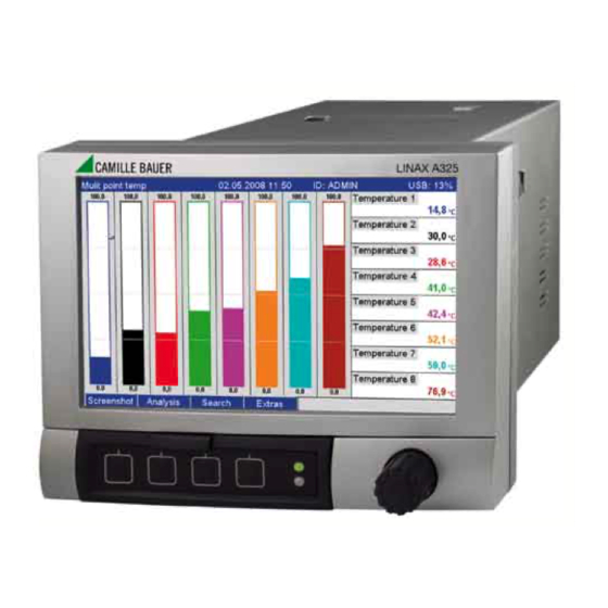
Page 1: Video Recorder
Operating instructions Video recorder LINAX A325... - Page 2 Brief overview Integrated Operating Instructions The unit's simple control system enables you to perform commissioning for many applications without the need for hardcopy operating instructions. Your unit displays instructions at the push of a button directly on screen. These instructions are nevertheless delivered with the unit - they supplement the Operating Instructions in the unit.
- Page 3 Advanced Graphic Data Manager...
-
Page 4: Table Of Contents
Advanced Graphic Data Manager Table of contents Table of contents Safety instructions ....5 Maintenance ....117 Designated use . -
Page 5: Safety Instructions
Advanced Graphic Data Manager Safety instructions Safety instructions Designated use This unit is designed for the electronic acquisition, display, recording, analysis, remote transmission and archiving of analog and digital input signals in non-hazardous areas. • The unit is designed for installation in a panel or a cabinet and may only be operated in an installed state. -
Page 6: Return
Safety instructions Advanced Graphic Data Manager IT security measures in line with operators' security standards and designed to provide additional protection for the device and device data transfer must be implemented by the operators themselves. Return For a return, e.g. in case of repair, the device must be sent in protective packaging. The original packaging offers the best protection. -
Page 7: Identification
Advanced Graphic Data Manager Identification Identification Device designation 2.1.1 Nameplate Compare the nameplate on the top of the unit with the delivery note and with the following diagram: Made in Germany 2014 Graphic Data Manager D-87484 Nesselwang Ordercode: OSG40-xxxxxxxx Ser. No. : Xxxxxxxxxx 100-230 V AC ( ±10%) -
Page 8: Installation
Installation Advanced Graphic Data Manager Installation Incoming acceptance, transport, storage 3.1.1 Incoming acceptance After receiving the goods, check the following points: • Is the packaging or the content damaged? • Is the delivery complete? Compare the goods delivered with what you ordered. 3.1.2 Transport and storage Observe the following points:... - Page 9 Advanced Graphic Data Manager Installation 3.3.2 Panel mounting, Installation dimensions 195.2 141 (5.55) (7.69) (0.2) (1.06) 157.4 (6.20) 37.07 (1.46) 192.3 (7.57) 196 (7.72) 138 (5.43) (0.28) Fig. 3: Panel mounting and installation dimensions. All dimensions in mm or (inch) •...
-
Page 10: Post-Installation Check
Wiring Advanced Graphic Data Manager • A distance of min. 7 mm (0.28 inch) between the devices has to be observed if aligning the devices in the Y-direction (vertically above one another). • The devices can be arranged horizontally beside one another in the X direction without any spacing between the devices. - Page 11 Advanced Graphic Data Manager Wiring 4.1.2 Circuit diagram Cable RS 485 resistance RxD/TxD(+) RxD/TxD(-) Further units Digital in (D) 12-24 VDC Analog >5 mA 24 V - Power supply outputs (O) GNDx GNDx (Selectable in unit setup) 100-230 VAC 24 V AC/DC (±10%) (-10%;...
- Page 12 Wiring Advanced Graphic Data Manager 4.1.3 Auxiliary voltage output as transmitter power supply for 2-wire sensors External display (optional) Sensor 1 Sensor 2 On connecting channels 3-16 see terminal connections Ch1-2 Fig. 5: Connecting the auxiliary voltage output when using as transmitter power supply for 2-wire sensors in the current measuring range –...
-
Page 13: Terminal Assignment
Advanced Graphic Data Manager Wiring 4.1.4 Auxiliary voltage output as transmitter power supply for 4-wire sensors Ext. display (optional) Sensor 1 Sensor 2 On connecting channels 3-16 see terminal connections Ch1-2 Fig. 6: Connecting the auxiliary voltage output when using as transmitter power supply for 4-wire sensors in the current measuring range –... - Page 14 Wiring Advanced Graphic Data Manager 4.2.2 Supply voltage (power supply slot) Power unit type Terminal 100-230 V AC Phase L Zero conductor N Ground 24 V AC/DC Phase Zero conductor N or – Ground L or + 4.2.3 Relay (power supply slot) Type Terminal Alarm relay 1...
- Page 15 Advanced Graphic Data Manager Wiring 4.2.4 Digital inputs (power supply slot) If the auxiliary voltage is to be used for the digital inputs, the "–" terminal of the 24 V auxiliary voltage has to be connected to the "GND1" terminal. Type Terminal GND1...
- Page 16 Wiring Advanced Graphic Data Manager 4.2.6 Analog outputs (optional: slot 5) Type Terminal Analog output 1-2 Analog output Ground analog Analog output Ground analog 1 (+) output 1 (–) 2 (+) output 2 (–) 4.2.7 Relay (optional: slot 5) Type Terminal Relay Switchi...
- Page 17 Advanced Graphic Data Manager Wiring 4.2.8 Analog inputs (slot 1-5) The first digit (x) of the two-digit terminal number corresponds to the related channel (e.g. Ch1: 11, 12, 13, 14, 15, 16): Type Terminal Current/pulse/ (–) frequency input Voltage >1 V (–) Voltage ...
-
Page 18: Interface Connection
Wiring Advanced Graphic Data Manager Interface connection 4.3.1 USB at the front of the unit Fig. 7: Front of unit with open flap/keyboard 1: USB A socket "host" e.g. for USB memory stick, external keyboard, bar code reader or printer 2: USB B socket "function"... - Page 19 Advanced Graphic Data Manager Wiring 4.3.3 Points to note concerning USB units Note! The USB units are detected by the "plug-and-play" function. If several units of the same type (e.g. printer) are connected, only the first USB unit connected is available. Settings for the USB units are made in the setup.
- Page 20 Wiring Advanced Graphic Data Manager Requirements with regard to an external USB printer The printer must support PCL5c (or higher). Laser jet and ink jet printers are supported. The printouts are always color printouts (if supported by the printer). The printout has different shades of gray if you use a black/white printer.
- Page 21 Advanced Graphic Data Manager Wiring address, subnetmask or gateway from a DHCP server. Without DHCP, these settings have to be made directly in the unit (depending on the network to which the unit should be connected). • The IP address assigned by DHCP is required in the PC software supplied to be able to communicate with the unit.
-
Page 22: Degree Of Protection
Operation Advanced Graphic Data Manager • Ethernet Modbus TCP slave: Connection to SCADA systems (Modbus master). Up to 40 analog inputs and 14 digital inputs can be transmitted via Modbus and stored in the unit. Degree of protection At the front, the unit meets the requirements of ingress protection IP65. Post-connection check After connecting the unit, carry out the following checks: Device condition and specifications... -
Page 23: Display And Operating Elements
Advanced Graphic Data Manager Operation Display and operating elements Fig. 12: Device display/operating units Operating Operating function element (Item (Display mode = measured value display) No.) (Setup mode = operating in the Setup menu) "Navigator" jog/shuttle dial for operating with additional press function. In the Display mode: turn the dial to switch between the various signal groups. - Page 24 Operation Advanced Graphic Data Manager Operating Operating function element (Item (Display mode = measured value display) No.) (Setup mode = operating in the Setup menu) In the Display mode: alternating display indicating what percentage of the SD card or USB stick has already been written to.
-
Page 25: Entering Text And Numbers
Advanced Graphic Data Manager Operation Entering text and numbers A virtual keyboard is available for entering text and numbers. This is opened automatically if needed. Here, turn the navigator to select the corresponding character and press the navigator to accept it. Fig. -
Page 26: Confirming Error Messages
Operation Advanced Graphic Data Manager Symbol Explanation Symbol Explanation Information Intermediate statistics Confirmation Daily analysis Unit locked/operating lock Weekly analysis External communication Monthly analysis Sequence active (bar code reader Annual analysis waiting for input) Lower limit value Total analysis Upper limit value Save to SD card/USB stick Limit value gradient increasing Measured value simulation... -
Page 27: Communication; Installing The Pc Software
Advanced Graphic Data Manager Operation Communication; installing the PC software Version V1.25.0.0 (or higher) of the PC software supplied must be installed to be able to establish communication between the unit and the PC. To be on the safe side, you should install the current PC software package (CD–ROM supplied). - Page 28 Operation Advanced Graphic Data Manager Connecting the modem to the unit: The modem's original cable cannot be used for this because the unit and the modem have the same pin assignments at the interface plug. For this reason, if possible use the modem cable "RXU10-A1" which is available as an accessory.
- Page 29 Advanced Graphic Data Manager Operation 5.6.5 Communication via Ethernet (TCP/IP) In principle, all units equipped with an internal Ethernet interface can be integrated into a PC network (TCP/IP Ethernet). The unit(s) can be accessed by any of the PCs in the network using PC software supplied. There is no need to install driver software ("COM redirection") on the PC because the PC software supplied has direct access to the Ethernet.
- Page 30 Operation Advanced Graphic Data Manager Now enter the IP address. The port address is 8000. The unit address set at the unit and the release code must also be set correctly here. Fig. 17: Entering the IP address of the new unit (example) Confirm the entry with "Continue"...
-
Page 31: Commissioning And Use During Operation
Advanced Graphic Data Manager Commissioning and use during operation Commissioning and use during operation Installation check Make sure that all post-connection checks have been carried out before you put your unit into operation: • See Section 3.4 'Post-installation check' • Checklist in Section 4.5 'Post-connection check' Switching on the device Once the operating voltage is applied, the display lights up and the unit is ready for operation. -
Page 32: Setup
Commissioning and use during operation Advanced Graphic Data Manager Setup 6.3.1 General information You can also put your unit into service and/or configure it via PC and the PC software supplied. The following are available for this: Front USB B system interface ( Page 33) SD card slot for reading in the parameters stored on the SD card (... - Page 33 Advanced Graphic Data Manager Commissioning and use during operation 6.3.3 Setup via interface and PC software supplied RS232 Ethernet, RS485 Example: Setup via PC software supplied Procedure for setup via interface and PC software supplied: Start ▾ Install the PC software supplied on the PC or laptop (see Section 5.6) ▾...
- Page 34 Commissioning and use during operation Advanced Graphic Data Manager Procedure for setup via interface and PC software supplied: In order to be able to use this function, the unit must already be created in the PC database or has to be created beforehand. Connect the unit interface (RS232 / RS485, USB or Ethernet) to the PC.
- Page 35 Advanced Graphic Data Manager Commissioning and use during operation Risk of data loss! Correct and safe functioning is only guaranteed with genuine SD cards of the manufacturer (see "Accessories", Section 8). 6.3.5 Setup via USB stick Save the unit settings on the PC onto a USB stick using the PC software supplied. This setup file can then be imported into the unit.
- Page 36 Commissioning and use during operation Advanced Graphic Data Manager 6.3.6 Setup directly at the unit (using keys/navigator) Key functions in the setup The function of the operating keys is described in the fields directly above the corresponding keys on the screen. Free fields mean that no function is currently assigned to the keys in question. •...
-
Page 37: The Setup Screen (In The Main Menu)
Advanced Graphic Data Manager Commissioning and use during operation The Setup screen (in the main menu) Two Setup modes are available: the Standard setup and the Expert setup. All the settings that are needed to operate the unit can be made in the Standard setup. Additional settings are made in the Expert setup (e.g. - Page 38 Commissioning and use during operation Advanced Graphic Data Manager Fig. 22: Release code for Expert setup (factory setting: 0000) Fig. 23: The Expert setup The individual parameters are summarized in the Setup menu in the following sections: Direct access Expert setup Direct access to active operating items (rapid access).
- Page 39 Advanced Graphic Data Manager Commissioning and use during operation • Any settings that are displayed in gray cannot be selected/cannot be changed (only notes, or option not available/not activated). • With the factory setting "0000" for the release code (delivery status), configuration is possible at any time.
- Page 40 Commissioning and use during operation Advanced Graphic Data Manager 6.4.1 Setup - System Settings that are not channel specific, this means date, time, communication etc. Procedure for basic settings in the "System" menu: Start ▾ Select an operating language from the list ▾...
- Page 41 Advanced Graphic Data Manager Commissioning and use during operation Fig. 24: Setup - System "System" menu Configurable parameters Direct access items (factory settings are highlighted in bold) code Language Select unit operating language. Factory setting: English 10000/000 Device tag Individual unit identifier (max. 22 characters). Factory setting: Device 1 10005/000 Is also saved on the SD card.
- Page 42 Commissioning and use during operation Advanced Graphic Data Manager "System" menu Configurable parameters Direct access items (factory settings are highlighted in bold) code Submenu Here you can find various date and time settings. "Date/time setup" Fig. 25: Setup - System, submenu "Date/time setup" Date format Select in which format the date is to be set and displayed.
- Page 43 Advanced Graphic Data Manager Commissioning and use during operation "System" menu Configurable parameters Direct access items (factory settings are highlighted in bold) code Day, when in the autumn a change from summer to normal time occurs. 11065/000 Only for "Manual summer time Picklist: Sunday, Monday to Saturday changeover"...
- Page 44 Commissioning and use during operation Advanced Graphic Data Manager "System" menu Configurable parameters Direct access items (factory settings are highlighted in bold) code Set point code The unit is protected by a release code. If a set point code has been set 18010/000 Only if the release code is up then the user can change the alarm set points after entering this code...
- Page 45 Advanced Graphic Data Manager Commissioning and use during operation "System" menu Configurable parameters Direct access items (factory settings are highlighted in bold) code "Baudrate": transmission rate ("baudrate") - must match the settings of 14105/000 the PC software supplied. "Data bits": make sure the setting matches that of the PC software 14110/000 supplied! Fixed settings - cannot be changed.
- Page 46 Commissioning and use during operation Advanced Graphic Data Manager "System" menu Configurable parameters Direct access items (factory settings are highlighted in bold) code IP address 14315/000 Enter the IP address for the unit here. This IP address is assigned by your network administrator.
- Page 47 Advanced Graphic Data Manager Commissioning and use during operation "System" menu Configurable parameters Direct access items (factory settings are highlighted in bold) code Analysis 2 Here, choose whether a daily, weekly, monthly or annual analysis should 17005/000 Analysis 3 be performed. 17010/000 Analysis 4 "No": no analysis...
- Page 48 Commissioning and use during operation Advanced Graphic Data Manager "System" menu Configurable parameters Direct access items (factory settings are highlighted in bold) code Submenu "External Settings for the external data carrier, amongst other things which data are to be stored in which format on the memory"...
- Page 49 Advanced Graphic Data Manager Commissioning and use during operation "System" menu Configurable parameters Direct access items (factory settings are highlighted in bold) code Submenu "Messages" Settings for displaying/confirming messages. For example, messages can be: (only available in the – Messages triggered by set points Expert setup) –...
- Page 50 Commissioning and use during operation Advanced Graphic Data Manager "System" menu Configurable parameters Direct access items (factory settings are highlighted in bold) code Screensaver “Switched off”: LCD is always switched on 13000/000 "On after x min": display turns dark after 10, 30 or 60 minutes. All other functions remain in operation.
- Page 51 Advanced Graphic Data Manager Commissioning and use during operation "System" menu Configurable parameters Direct access items (factory settings are highlighted in bold) code Timeout sequences Specify after how many seconds an order sequence is aborted if the 10960/000 necessary data are not read in. User input: 10 to 180 seconds;...
- Page 52 Commissioning and use during operation Advanced Graphic Data Manager ▾ Enter the measured value correction ("offset") for the start and end of the measuring range (not necessary for pulse/ frequency) ▾ Configure the failsafe mode (e.g. in the event of cable open circuit) ▾...
- Page 53 Advanced Graphic Data Manager Commissioning and use during operation "Inputs" menu Configurable parameters Direct access items (factory settings are highlighted in bold) code Plot type The universal inputs are scanned at 100ms cycles. Depending on the 20025/000 save cycle, the selected data are determined from the scanned values and saved (e.g.
- Page 54 Commissioning and use during operation Advanced Graphic Data Manager "Inputs" menu Configurable parameters Direct access items (factory settings are highlighted in bold) code Upper frequency Specify the upper frequency that corresponds to the end of the 20075/000 Only for Signal "Frequency measuring range.
- Page 55 Advanced Graphic Data Manager Commissioning and use during operation "Inputs" menu Configurable parameters Direct access items (factory settings are highlighted in bold) code Submenu: Measured value For determining the correction values to offset measurement section correction tolerances. Follow these instructions: 1.
- Page 56 Commissioning and use during operation Advanced Graphic Data Manager "Inputs" menu Configurable parameters Direct access items (factory settings are highlighted in bold) code Submenu: Totalization Settings only required if this analog measuring point is to be integrated for calculating the volume for example. For analysis periods, see "Signal analysis".
- Page 57 Advanced Graphic Data Manager Commissioning and use during operation "Inputs" menu Configurable parameters Direct access items (factory settings are highlighted in bold) code Submenu: Fault mode (only Settings that lay down how this channel is to react under fault conditions available in the Expert (e.g.
- Page 58 Commissioning and use during operation Advanced Graphic Data Manager Only visible for mathematics (option) Fault mode Failsafe mode if an input signal/variable is invalid (e.g. cable open circuit, invalid result of mathematics calculation; e.g. dividing by zero). Set failsafe "Invalid" channel Dependent channels mode Value is invalid...
- Page 59 Advanced Graphic Data Manager Commissioning and use during operation Setup – Inputs, submenu: digital inputs Procedure for setting the signals of the digital inputs: 1. Start ▾ 2. Select the function of the digital channel (also optionally possible via "Modbus" or "Profibus" fieldbus) ▾...
- Page 60 Commissioning and use during operation Advanced Graphic Data Manager The descriptions of the operating items for optional application packages can be found in the additional Operating Instructions on the CD-ROM or as hardcopy (part of the scope of delivery). "Inputs" menu Configurable parameters Direct access items...
- Page 61 Advanced Graphic Data Manager Commissioning and use during operation "Inputs" menu Configurable parameters Direct access items (factory settings are highlighted in bold) code Channel ident. Measurement point name (e.g. "Pump") or description of the function of 40010/000 to this input (e.g. "Fault message"). 16-character entry. 40010/013 Factory setting: digital x Engineering unit...
- Page 62 Commissioning and use during operation Advanced Graphic Data Manager "Inputs" menu Configurable parameters Direct access items (factory settings are highlighted in bold) code Save event Determines whether the condition change from low to high or high to 40065/000 to Only for "On/off event" and low is stored in the event log.
- Page 63 Advanced Graphic Data Manager Commissioning and use during operation "Inputs" menu Configurable parameters Direct access items (factory settings are highlighted in bold) code Set point Select what limit value should be switched on and off by means of this 40095/000 to Only for "Action –...
- Page 64 Commissioning and use during operation Advanced Graphic Data Manager Setup – Inputs, submenu: Mathematic (option) Settings only required if measured values of the input signals are to be mathematically linked. Up to 8 mathematics channels can be used. Depending on the selected function, the unit's user interface adapts itself, so that each time only parameters that are required for safe unit functioning have to be checked/set.
- Page 65 Advanced Graphic Data Manager Commissioning and use during operation "Inputs" menu Configurable parameters Direct items (factory settings are highlighted in bold) access code The result is Specify what data type the calculation returns. This setting affects how the 30025/000 to channel saves and is displayed.
- Page 66 Commissioning and use during operation Advanced Graphic Data Manager "Inputs" menu Configurable parameters Direct items (factory settings are highlighted in bold) access code Decimal point Number of places after decimal point for the display. Picklist: 0 to 5 number 30050/000 to Only for "The result is –...
- Page 67 Advanced Graphic Data Manager Commissioning and use during operation "Inputs" menu Configurable parameters Direct items (factory settings are highlighted in bold) access code Totalization 34000/000 to Using the totalization function, the volume (in m) can be calculated from 34000/007 an analog signal (e.g. flow in m/h). Picklist: no, yes Totalization base 34005/000 to Select the corresponding time base.
- Page 68 Commissioning and use during operation Advanced Graphic Data Manager Setup – Inputs, submenu: Linearization "Inputs" menu Configurable parameters Direct access items (factory settings are highlighted in bold) code Submenu: First select the analog input to be linearized. The "Linearization" menu item only appears for active analog Linearization, inputs.
- Page 69 Advanced Graphic Data Manager Commissioning and use during operation "Inputs" menu Configurable parameters Direct access items (factory settings are highlighted in bold) code Check table Here, you can check whether the linearization table has been entered 36035/000 to correctly. 36035/015 Picklist: no, yes Submenu: Points x Enter the points for the linearization table here.
- Page 70 Commissioning and use during operation Advanced Graphic Data Manager 6.4.3 Setup - Outputs Settings only required if outputs (e.g. relays or analog outputs) are to be used. Setup Outputs, submenu: Analog/pulse outputs, Analog output 1-2 "Outputs" menu Configurable parameters Direct items access (factory settings are highlighted in bold)
- Page 71 Advanced Graphic Data Manager Commissioning and use during operation "Outputs" menu Configurable parameters Direct items (factory settings are highlighted in bold) access code Submenu: Measured value Here, you can correct the current value output (only required if the unit correction processing the values further cannot balance possible measurement Only for signal "0/4-20 mA"...
- Page 72 Commissioning and use during operation Advanced Graphic Data Manager Setup – Outputs, submenu: Relay "Outputs" menu Configurable parameters Direct access items (factory settings are highlighted in bold) code Submenu: Relay, relay Various relay settings (e.g. operating mode) The basic version of the unit has 6 relays. 6 additional relays are also available on the optional "Digital card". Setup for the selected relay: Fig.
- Page 73 Advanced Graphic Data Manager Commissioning and use during operation 6.4.4 Setup - Application Specify the various application-specific settings (e.g. limit values, signal grouping, text, softkeys, Web server, telealarm (option)). Depending on the selected function, the unit's user interface adapts itself, so that each time only parameters that are required for safe unit functioning have to be checked/set.
- Page 74 Commissioning and use during operation Advanced Graphic Data Manager "Application" Configurable parameters Direct menu items (factory settings are highlighted in bold) access code Submenu: The measured values can be monitored for alarm set point violation. A relay can be switched or an event Set points, set point x message displayed on violation.
- Page 75 Advanced Graphic Data Manager Commissioning and use during operation "Application" Configurable parameters Direct menu items (factory settings are highlighted in bold) access code Set point Counter alarm set point in the engineering units set up, e.g. m, piece, ..37035/000 to 37035/099 Hysteresis type...
- Page 76 Commissioning and use during operation Advanced Graphic Data Manager "Application" Configurable parameters Direct menu items (factory settings are highlighted in bold) access code Reset relay "If LV no longer violated": the relay remains switched as long as the 37090/000 to limit value is violated.
- Page 77 Advanced Graphic Data Manager Commissioning and use during operation "Application" Configurable parameters Direct menu items (factory settings are highlighted in bold) access code Save cycle Specify the save cycle for saving this group during normal operation (see 38105/000 to also limit value / save cycle). 38105/009 Note: the save cycle is independent of the measured value display.
- Page 78 Commissioning and use during operation Advanced Graphic Data Manager "Application" Configurable parameters Direct menu items (factory settings are highlighted in bold) access code Display green Color for displaying the assigned input. 38160/000 to Note: Only the channels that were assigned to a group are saved. 38160/009 Channels can be assigned to several groups.
- Page 79 Advanced Graphic Data Manager Commissioning and use during operation "Application" Configurable parameters Direct menu items (factory settings are highlighted in bold) access code Bar graph Specify the direction in which the bar graphs should be drawn. 38220/000 to Picklist: vertical (bottom->top), vertical (top->bottom), horiz. (left- 38220/009 >right), horiz.
- Page 80 Commissioning and use during operation Advanced Graphic Data Manager "Application" Configurable parameters Direct menu items (factory settings are highlighted in bold) access code Submenu: Web server Setup for operation of the unit as a Web server. Instantaneous values can be read off using an Internet Browser, e.g.
- Page 81 Advanced Graphic Data Manager Commissioning and use during operation "Application" Configurable parameters Direct menu items (factory settings are highlighted in bold) access code Color printer Please set up if you´re using a black and white or a color printer. 67025/000 Picklist: Yes (=color printer), No (=b/w printer) Print direction Select the printing direction based on the properties of the printer you...
- Page 82 Commissioning and use during operation Advanced Graphic Data Manager 6.4.5 Expert - Diagnosis/Simulation Unit information and service functions for a swift unit check. "Expert" menu Configurable parameters Direct items (factory settings are highlighted in bold) access code Submenu: Diagnosis/ Displays important device information. Simulation, Device information/ENP Fig.
-
Page 83: Use During Operation - The "Extras" Menu
Advanced Graphic Data Manager Commissioning and use during operation Use during operation - the "Extras" menu Call up the "Extras" menu by pressing softkey 4: Fig. 52: "Extras" menu 6.5.1 Extras - Display/operation Changes the display mode, e.g. curve display, bar graph, digital display or event list. The various display modes have no influence on the signal recording. - Page 84 Commissioning and use during operation Advanced Graphic Data Manager "Extras" menu items, Description submenu: Display/operation Change group Select the group which should be displayed. Note: only the active groups are displayed. Picklist: group 1 – x Curve All channels are displayed over the total width. Maximum resolution in upscale direction. All the channels in a group are displayed horizontally (from right to left).
- Page 85 Advanced Graphic Data Manager Commissioning and use during operation "Extras" menu items, Description submenu: Display/operation Waterfall in ranges All the channels in a group are displayed vertically (from top to bottom). Each channel is displayed in its own chart zone. Accuracy of the plot is not influenced in this display mode.
- Page 86 Commissioning and use during operation Advanced Graphic Data Manager "Extras" menu items, Description submenu: Display/operation Digital display Display of the active analog measured values as digital values. The digital input is displayed as a status or counter/ operating time counter. Fig.
- Page 87 Advanced Graphic Data Manager Commissioning and use during operation "Extras" menu items, Description submenu: Display/operation Event log/audit trail Events such as alarm set point infringement and power failure are listed in the correct time sequence. Fig. 63: Event log/audit trail Adjust brightness Here, you can adjust the brightness of the display.
- Page 88 Commissioning and use during operation Advanced Graphic Data Manager 6.5.5 Extras - History (scrolling through saved measured values) You can scroll through the saved measured values here. Turn the navigator clockwise or counterclockwise to scroll back and forth between the measured value curves. You can change the speed with softkey 3 (slow "<"...
- Page 89 Advanced Graphic Data Manager Commissioning and use during operation 6.5.6 Extras - Search in trace Search for events or times in the internal memory. Fig. 66: Extras "Search in trace" "Search in trace" menu Description items (factory settings are highlighted in bold) Search criterion You can search for a specific time or event in the memory.
- Page 90 Commissioning and use during operation Advanced Graphic Data Manager Fig. 67: Extras "Search in trace" - Search results Subsequent reporting Under "Store text", comments can be entered on the specific time selected by pressing softkey 4 "Extras". The date and time are automatically taken from the search result. A predefined text can be selected or a new text can be entered (see "Setup –>...
- Page 91 Advanced Graphic Data Manager Commissioning and use during operation 6.5.7 Extras - Signal analysis Displays the analyses stored in the device. Fig. 69: Extras "Signal analysis" "Signal analysis" menu Description items (factory settings are highlighted in bold) Analysis 1-4 You can display the current analysis here (i.e. the analysis that is currently ongoing). Note! This option can only be selected if settings were made under "Setup ->...
- Page 92 Commissioning and use during operation Advanced Graphic Data Manager 6.5.8 Extras - SD card or USB stick Fig. 70: Extras "SD card" or "USB stick" Functions for measured data storage and unit setup on SD card or USB stick. The following functions are possible: Menu items "SD card"...
- Page 93 Advanced Graphic Data Manager Commissioning and use during operation Menu items "SD card" or Description "USB stick" Load user administration Loads all the settings and user accounts from the data carrier. The file has the extension .ids. Note: All the existing settings/accounts are overwritten! Screenshot Save the current measured value display as a bitmap on the SD card or on the USB stick.
- Page 94 Commissioning and use during operation Advanced Graphic Data Manager 6.5.9 Extras – Store text Save the text comments ("subsequent reporting") for a specific time. After entering the desired date and time, a predefined text can be selected or a new text can be entered (see "Setup –> Application –>...
- Page 95 Advanced Graphic Data Manager Commissioning and use during operation "Printout" menu items Description (factory settings are highlighted in bold) Current measured values Print out instantaneous measured values (all active channels). Screenshot Print out current measured value display (screenshot). 6.5.11 Extras - Screenshot Save the current measured value display as a bitmap on the SD card or the USB stick.
- Page 96 Commissioning and use during operation Advanced Graphic Data Manager "Set points" menu Configurable parameters items (factory settings are highlighted in bold) Set point Only with analog channels: Enter the analog set point in the preset engineering unit, e.g. Only with analog or digital channels in °C, bar, etc.
-
Page 97: Use During Operation - The Main Menu
Advanced Graphic Data Manager Commissioning and use during operation Use during operation - the main menu Call up the main menu by pressing the navigator: Fig. 73: Main menu 6.6.1 Main menu - Language The default setting for the operating language is English. A different operating language can be configured here. - Page 98 Commissioning and use during operation Advanced Graphic Data Manager 6.6.4 Main menu - Diagnosis/simulation Unit information and service functions for a swift unit check. Fig. 74: Main menu, submenu: Diagnosis/simulation "Diagnosis/ Configurable parameters Simulation" menu (factory settings are highlighted in bold) items Current diagnosis Displays the current diagnosis message.
- Page 99 Advanced Graphic Data Manager Commissioning and use during operation "Diagnosis/ Configurable parameters Simulation" menu (factory settings are highlighted in bold) items LCD operating time Indicates how long the display of the unit was in operation. Submenu: Hardware Information on the hardware components, and what slots are assigned, with information on the software version.
- Page 100 Commissioning and use during operation Advanced Graphic Data Manager 6.6.5 Main menu - Expert Start the Expert setup. All the operating items of the device can be changed here (see Chap. 6.4). 6.6.6 Main menu - User administration Activate user administration Activate the security system if you want to protect the unit against unauthorized operation.
- Page 101 Advanced Graphic Data Manager Commissioning and use during operation "User Configurable parameters administration" (factory settings are highlighted in bold) menu items Password length Set the minimum number of characters passwords should contain. Note: this setting only affects new passwords entered. Picklist: 0, 1, 2, 3, 4, 5, 6, 7, 8, 9, 10 characters Password valid Specify how frequently the password has to be changed.
-
Page 102: Menu Items
Commissioning and use during operation Advanced Graphic Data Manager "User Configurable parameters administration" (factory settings are highlighted in bold) menu items Automatic logout A user is logged off automatically if a key is not pressed for a specific time. Note: the user is not logged off if he/she is in the Setup menu. If users are automatically logged off while they are in the Setup menu, the changes made to the settings are discarded. - Page 103 Advanced Graphic Data Manager Commissioning and use during operation 6.6.7 Creating process-related graphics on the PC The process-related graphic always consists of two files: The background graphic (*.bmp) A configuration file (*.ini) • Process-related graphics can only be created on the PC. •...
- Page 104 Commissioning and use during operation Advanced Graphic Data Manager Abbreviation: Description: <font> Select the font size to be used for displaying the measured value: 0 = small (16 pixels) 1 = medium (24 pixels) 2 = large (38 pixels) 3 = very large (78 pixels) Font 0 is used for all other values.
- Page 105 Advanced Graphic Data Manager Commissioning and use during operation 6.6.8 The context menu The context menu is available for all the measured value displays (apart from the event log). Launch: press the navigator 3-4 seconds. If an external keyboard is connected, the context menu can also be called using Shift+Enter.
- Page 106 Commissioning and use during operation Advanced Graphic Data Manager "Context menu" Configurable parameters menu items (factory settings are highlighted in bold) Display in process screen Switch the channel in the process-related graphic on or off. Note: This does not affect the process for storing the measured value or the configuration.
- Page 107 Advanced Graphic Data Manager Commissioning and use during operation Settings for the mathematics channels, Formula editor Open the formula editor at "Setup -> Inputs -> Math -> Math x -> Formula". A text field with the formula currently used appears. If the field is empty, a formula has not yet been defined for the mathematics channel in question: A formula with up to 200 characters can be created with this editor.
- Page 108 Commissioning and use during operation Advanced Graphic Data Manager Signal type: Type Description Instantaneous value (measured value) Status Counter time/operating time Validity: The status of an analog or math channel is returned. The value returned by the function is 0 if: •...
- Page 109 Advanced Graphic Data Manager Commissioning and use during operation 6.7.3 Operators Operators for calculation: Operator Function Addition Subtraction/negative sign Multiplication Division Modulo (remainder of division x/y), see function "mod" x to the power of y Operators for comparison: Operator Function >...
- Page 110 Commissioning and use during operation Advanced Graphic Data Manager 6.7.4 Functions Standard functions: Function Syntax Description Example ln(number) Returns the natural logarithm of a number. Natural logarithms ln(86) = have a constant e (2.71828182845904) as their base. The 4.454347 result is undefined for values = 0. The unit continues to work with 0.
- Page 111 Advanced Graphic Data Manager Commissioning and use during operation The following functions expect a radian angle as the argument. If the angle is given as degrees, it has to be converted to the radian by multiplying by pi()/180. Alternatively, the "rad" function can be used: Function Syntax...
- Page 112 Commissioning and use during operation Advanced Graphic Data Manager Range functions: The XX in the following functions stands for one of the inputs described under Chap. 6.7.1. Range functions can only be executed via one type of input. Function Syntax Description Example...
-
Page 113: Settings For The Mathematics Channels, Formula Editor
Advanced Graphic Data Manager Commissioning and use during operation Meeting the requirements of 21 CFR 11 6.8.1 General notes Prior to using electronic signatures, a hand-signed letter should be sent to the Office of Regional Operations (HFC–-100) 5600 Fishers Lane Rockville, MD 20857 informing it that the company intends to use electronic documents/signatures in the future. -
Page 114: Measured Value Storage
Commissioning and use during operation Advanced Graphic Data Manager Measured value storage Measure Save Display (internal, FIFO) Display by access to internal memory Copy saved on SD-card or USB-stick Data transfer using CF/USB Archiving Data bank / (external, batch) analysis (at PC) Fig. -
Page 115: Data Analysis And Visualization Using Pc Analysis Software
Advanced Graphic Data Manager Commissioning and use during operation 6.9.2 Operating mode of the SD card and USB stick Without affecting the internal memory, data packages are copied block-by-block to the SD card. Tests are also made to determine whether the data have been written without any errors. The same happens when storing the data on the PC with the PC software contained in the scope of delivery. - Page 116 Commissioning and use during operation Advanced Graphic Data Manager 6.10.2 Data transmission to the PC software supplied The current PC software must be installed on a PC (for installation instructions, see description on CD–ROM or Section 5.6 of these Operating Instructions). SD-Card, USB-Stick *.csv Fig.
-
Page 117: Maintenance
Advanced Graphic Data Manager Maintenance ® 6.10.4 Viewing data in a spreadsheet (e.g. MS-Excel SD-Card, USB-Stick *.csv MS Excel Fig. 82: Data analysis in spreadsheet Select "Open format (*.csv)" (comma separated values) as the save mode in the unit under " Main menu –>... - Page 118 Maintenance Advanced Graphic Data Manager Open the "Extras -> Special device functions -> (Select unit) -> Transfer program" menu. Select interface parameters (Com port or USB device) Select desired program file (*.prg) and confirm with OK.
-
Page 119: Accessories
Advanced Graphic Data Manager Accessories Accessories When ordering accessories, please quote the serial number of the device! The accessory parts content installation instructions! Device-specific accessories The following accessories are available: Order code Accessory 71007465 Cable USB-A - USB-B, 2 m (6.6 ft) 71038635 "Industrial Grade"... - Page 120 Accessories Advanced Graphic Data Manager Order code Accessory RSG40X- Retrofit kit desk top version; Weight (maximum configuration): approx. 4.4 kg (9.6 lb) Cable + 2 pin european plug: RSG40X-HH Cable + norm swiss plug: RSG40X-HK Cable + US plug: RSG40X-HI 293.4 mm (11.6 “) 236 mm (9.29 “) 184 mm (7.24 “)
-
Page 121: Troubleshooting
Advanced Graphic Data Manager Troubleshooting Troubleshooting Diagnose/simulation in the main menu Unit information and service functions for a swift unit check. For descriptions, see Section 6.6.4. Troubleshooting instructions Dead pixels: Dead pixels refer to pixels on LCD and TFT displays that are defect due to the technology or manufacturing techniques used. -
Page 122: System Error Messages
Troubleshooting Advanced Graphic Data Manager Problem: Cause: Remedy: RS232/RS485, Ethernet interface Cable defective Replace cable (Accessories, see Section 8) not working Incorrect connection assignment Use original cables. Incorrect unit address Check and set correctly. Incorrect interface parameters Check and set correctly. CPU defective Contact the supplier's service department! Modem connection not working... - Page 123 Advanced Graphic Data Manager Troubleshooting M-code error messages: Code Brief error description Remedial action M102 Overrange Check sensor M103 Underrange Check sensor M104 Measured value is invalid Check formula of the mathematics channel; Check unit hardware M304 SD card is full! Replace SD card M305 USB stick is full!
- Page 124 Troubleshooting Advanced Graphic Data Manager Code Brief error description Remedial action F319 No IP address could be obtained from the DHCP Check the connections and communication settings. server! Contact your network administrator. F320 No connection to the e-mail server. Check the connections and communication settings F321 E-mail could not be sent! Check the connections and communication settings...
- Page 125 Advanced Graphic Data Manager Troubleshooting Error code Error description Remedial action 550 must be authenticated The SMTP server demands authentication. Please enter a user name and a password. Ask your system administrator. 550 Sender address does not belong The sender name must correspond to the user name. Use the user name as the sender name.
-
Page 126: Spare Parts
Troubleshooting Advanced Graphic Data Manager Spare parts If ordering spare parts, please specify the serial number of the unit! Installation instructions are included with the spare part. 9.5.1 Illustration of spare parts Fig. 83: Illustration of spare parts 9.5.2 List of spare parts, retrofit parts Pos. - Page 127 Advanced Graphic Data Manager Troubleshooting Pos. Order No. Identifier RSG40X–NC Power supply 24 V (-10%; +15%) AC/DC 71037410 Terminal, pluggable, 4-pin for relay 2+3 and relay on digital I/O option card 71037351 Terminal, pluggable, 10-pin for digital inputs on digital I/O option card 71037350 Terminal, pluggable, 4-pin for analog outputs on digital I/O option card RSG40X–BA...
-
Page 128: Return
Troubleshooting Advanced Graphic Data Manager 9.5.3 Device software spare parts structure (upgrading options) Pos. Order No. Identifier RSG40A1-... Device software Software (make sure to specify serial number) Mathematics option Telealarm Batch Wastewater + rain spillway basin RSB + telealarm Energy software, water + steam + mathematics Telealarm + Energy software, water + steam + mathematics Option Neutral version... - Page 129 Advanced Graphic Data Manager Troubleshooting Device software Software modification PC software SQL Reporting Operating version/date version software version Instructions/date 02.10.02 / 07.2011 New functions/improvements and V1.27.5.0 and higher V1.01.00.08 and higher BA247R/09/en/02.11 bug fixing 02.11.07 / 06.2014 Bug fixing; Anpassungen V1.27.10.0 and higher V1.02.00.11 and higher BA00247R/09/en/03.14...
-
Page 130: Technical Data
Technical data Advanced Graphic Data Manager Technical data 10.1 Input 10.1.1 Analog multifunction inputs Number Standard version without universal inputs. Optional multifunction input cards (slot 1-5) each with 4 universal inputs (4/8/12/16/20). Function You can choose between the measured variables U, I, RTD, TC, pulse input or frequency input for each universal input. - Page 131 Advanced Graphic Data Manager Technical data Measured Measuring range Maximum measured error Input variable of measuring range (oMR) resistance 1 MOhm Thermocouples Typ B (Pt30Rh-Pt6Rh): 42 to 1820 °C (108 to 3308 °F) (IEC 60584-1) ±0,15% oMR as of 600 °C (1112 °F) (TC) Typ C (W5Re-W26Re): 0 to 2315 °C (32 to 4199 °F) (IEC 60584-1) ±0,15% oMR as of 500 °C (932 °F)
-
Page 132: Output
Technical data Advanced Graphic Data Manager Converter resolution 24 bit Totalization The interim value, daily value, weekly value, monthly value, annual value and overall value can be determined (13-digit, 64 bit). 10.1.2 Digital inputs Number Standard version: 6 digital inputs Optional digital card (slot 5): 8 additional digital inputs Input level To IEC 61131-2:... - Page 133 Advanced Graphic Data Manager Technical data It is not permitted to mix low voltage and safety extra low voltage (do not mix SELV circuits and low voltage). Response time: max. 400 ms Maximum DC contact load: 30 V / 3 A Maximum AC contact load: 230 V / 3 A 10.2.3...
-
Page 134: Power Supply / Terminal Diagram
Technical data Advanced Graphic Data Manager Not galvanically isolated from one another. Galvanic isolation is only available for digital inputs between the power unit and the optional digital card. 10.3 Power supply / terminal diagram 10.3.1 Electrical connection (wiring diagram) (Wiring diagram, see Section 4 "Wiring") 10.3.2 Supply voltage... -
Page 135: Connection Data Interface, Communication, Operation
Advanced Graphic Data Manager Technical data 10.4 Connection data interface, communication, operation 10.4.1 USB ports: USB at the front of the unit Fig. 84: Front of unit with open flap/keyboard 1: USB A socket "host" e.g. for USB memory stick, external keyboard, bar code reader or printer 2: USB B socket "Function"... - Page 136 Technical data Advanced Graphic Data Manager USB bar code reader reference list: Datalogic Gryphon D230; Metrologic MS5100 Eclipse Series; Symbol LS2208 10.4.2 Ethernet interface (interface slot): An IEEE 802.3-compatible connection is available on a shielded RJ45 plug connector on the rear of the unit as the network connection.
-
Page 137: Performance Characteristics
Advanced Graphic Data Manager Technical data 10.5 Performance characteristics 10.5.1 Reference operating conditions Ambient temperature: 25 °C ±5 K (77 °F ±9 °F) Air humidity: 55% ±10% r.h. 10.5.2 Maximum measured error See Input, see Section 10.1.1 10.5.3 Temperature drift Cu50, Cu53, Cu100, Pt46 and Pt50: max. -
Page 138: Mechanical Construction
Technical data Advanced Graphic Data Manager 10.7.5 Electrical safety IEC 61010-1, protection class I Low voltage: overvoltage category II Environment <3000 m (<9843 ft) above MSL (mean sea level) 10.7.6 Electromagnetic compatibility (EMC) Interference immunity: To IEC 61326 (industrial environment) and NAMUR NE21: •... - Page 139 Advanced Graphic Data Manager Technical data 195.2 141 (5.55) (7.69) (0.2) (1.06) 37.07 157.4 (6.20) (1.46) 192.3 (7.57) 196 (7.72) 138 (5.43) (0.28) Fig. 85: All dimensions in mm or (inch)
- Page 140 Technical data Advanced Graphic Data Manager Design, dimensions desk top housing: 293.4 mm (11.6 “) 184 mm (7.24 “) 236 mm (9.29 “) 212.6 mm (8.37“) Fig. 86: All dimensions in mm or (inch) 10.8.2 Weight • Panel-mounted instrument, maximum configuration: approx. 2.7 kg (5.9 lb) •...
-
Page 141: Human Interface
Advanced Graphic Data Manager Technical data • Side profiles: extruded aluminum sheath (powder-coated) • Profile ending: pigmented Polyamide • Housing feet: pigmented Polyamide, glass fiber reinforced 10.9 Human interface 10.9.1 Display elements Type: Wide-screen TFT color graphic display Size (Screen size): 178 mm (7") Resolution: Wide VGA 384,000 pixels (800 x 480 pixels) - Page 142 Technical data Advanced Graphic Data Manager Fig. 89: Waterfall Fig. 90: Waterfall in ranges Fig. 91: Circular chart Fig. 92: Bar graph Fig. 93: Digital display Fig. 94: Instrument display Fig. 95: Event log Fig. 96: Process display...
-
Page 143: Operating Elements
Advanced Graphic Data Manager Technical data 10.9.2 Operating elements Unit keyboard: Option of operation and configuration via navigator (jog/shuttle dial) and 4 softkeys on the front side in interactive dialog with the screen, or using PC software supplied. Integrated online help displayed at the press of a button. - Page 144 Technical data Advanced Graphic Data Manager Typical recording length: Prerequisites for following tables: • No limit value violation/event storage • Digital input not used • Signal analysis deactivated Note! Frequent entries in the event log reduce the memory availability! Internal memory 256 MB (weeks, days, hours): Analog inputs Memory cycle 5 Memory cycle 1...
-
Page 145: 10.10 Certificates And Approvals
Advanced Graphic Data Manager Technical data 10.9.4 Real time clock (RTC) Configurable summer time/normal time automated system Power reserve: buffering via lithium battery (buffering 6 years; replace after 10 years) Deviation: <10 min./year Time synchronization possible via PC software supplied or via control input. 10.9.5 Remote control, communication •... - Page 146 Technical data Advanced Graphic Data Manager • Brief Operating Instructions (KA248R09) • Operating Instructions Supplementary Description "PROFIBUS DP" (BA256R09) • Operating Instructions Supplementary Description "Modbus RTU / TCP Slave" (BA00260R09) • Operating Instructions Supplementary Description "Modbus RTU Master" (BA00301R09) • Operating Instructions Supplementary Description "Überwachung von Milcherhitzeranlagen" (BA261R09de) •...
-
Page 147: Index
Advanced Graphic Data Manager Index Index Numerics Configuring by PC ....... 32 Configuring the operating language . - Page 148 Advanced Graphic Data Manager Index Electromagnetic compatibility (EMC)....138 Interference immunity ......138 Emission .
- Page 149 Advanced Graphic Data Manager Index Scan rate ........131 Screen size .
- Page 150 Advanced Graphic Data Manager Index Transport and storage ......8 Type ......... 74 UL-listed for Canada and USA .
- Page 151 Advanced Graphic Data Manager Index...
- Page 152 BA00247O/09/en/03.14 71252214 FM10...
Need help?
Do you have a question about the LINAX A325 and is the answer not in the manual?
Questions and answers