Table of Contents
Advertisement
Quick Links
Advertisement
Table of Contents

Related Manuals for GE NetworX V3


Summary of Contents for GE NetworX V3
-
Page 1: Installation Manual
NetworX Version 3 Alarm System Installation Manual 1070138... - Page 2 SUPPLIER OR VISIT US ONLINE AT WWW.UTCFIREANDSECURITY.COM. Trademarks and patents GE and the GE monogram are trademarks of the General Electric Company and are under license to UTC Fire & Security, 9 Farm Springs Road, Farmington, CT 06034-4065. NetworX product and logo are registered trademarks of UTC Fire & Security.
-
Page 3: Table Of Contents
References..................................... 9 Section A Installing and programming a basic system ................10 Chapter A1 Introducing the NetworX V3 system..................11 NetworX V3 diagram ..............................11 NetworX V3 technical specifications........................13 Auxiliary current and battery capacity ....................14 NetworX V3 system .................................15 Parts of the system................................16 Keypads ....................................19... - Page 4 NetworX Version 3 Installation Manual Quick User Menu..............................41 Selecting a menu option...............................41 Changing a menu option..............................41 Changing selection list entries........................41 Changing binary entries ..........................42 Changing numeric entries ..........................42 Changing phone numbers and phone prefixes...................42 Exiting the menu system ..............................43 Editing text ..................................43 Overview ................................43 Example..................................44 Word library................................45...
- Page 5 Setup for auto-test, auto-arm and opening/closing times ............113 Communicator codes for slow speed formats only................115 Programming partition parameters.......................122 Programming zone configuration groups...................125 NetworX V3 location-programming worksheets ...................139 Chapter B3 Programming the NX-1048 keypad..................152 Overview....................................152 Configuring the NX-1048 keypad features .......................154 General options..............................154...
- Page 6 NetworX Version 3 Installation Manual Assigning X-10 devices ..........................161 Copying keypad settings..........................161 Configuring keypad text ..........................161 Setting installer messages ......................... 162 Setting the keypad partition and keypad number................162 Setting the exit buzzer options......................... 162 Glossary..................................... 164 Technical specifications.............................
- Page 7 NetworX Version 3 Installation Manual Primary and secondary reporting ......................199 GSM/GPRS module as backup (SMS / GPRS) ..................200 GSM/GPRS module as backup (audio reporting) ................200 Setting up polling ............................202 Upload/download............................202 Reporting summary ............................203 Using the GSM/GPRS module ..........................207 Obtaining the GSM/GPRS module status.....................207 Troubleshooting...............................208 Autotest ................................208 Reporting protocols and formats ..........................209...
- Page 8 NetworX Version 3 Installation Manual Glossary..................................... 248 Technical Specifications ............................249 Chapter B10 Programming with the DL900 software ................250 Other methods of programming ........................... 250 Connecting the panel to the computer ......................250 Connecting using a serial port ......................... 250 Connecting using a modem ........................
-
Page 9: Preface
References For more information, refer to the following: NetworX V3 Menu Structure This menu structure provides a map of the NetworX V3 menu options, including those for all the additional modules. NX Expander Installation Guide This manual contains detailed information about additional modules and their installation. -
Page 10: Section A Installing And Programming A Basic System
NetworX Version 3 Installation Manual Section A Installing and programming a basic system... -
Page 11: Chapter A1 Introducing The Networx V3 System
Flash/DL900 jumper Antenna Mini USB connection Antenna GSM Modem (for status LEDs description, see page 194) GSM Antenna Connector PSTN Modem The number of onboard zones differs for particular panel models. Refer to “NetworX V3 technical specifications” on page 13. - Page 12 Relay 2 (normally closed) Telephone Tip Relay 2 NO Relay 2 (normally open) Telephone Ring Relay 2 C Relay 2 (common) House Telephone Ring The number of onboard zones differs for particular panel models. Refer to “NetworX V3 technical specifications” on page 13.
-
Page 13: Networx V3 Technical Specifications
NetworX Version 3 Installation Manual NetworX V3 technical specifications Table 1. Available NetworX V3 panel models Panel models Onboard zones capacity NX-5 NX-7 NX-9, NX-11 NX-10 Table 2. NetworX V3 technical specifications Mains power specifications NX-xx(-GSM)-EUR NX-xx(-GSM)-LB-EUR Mains input voltage 230 VAC +10%, −15%, 50Hz... -
Page 14: Auxiliary Current And Battery Capacity
NetworX Version 3 Installation Manual Standard onboard outputs NX-xx(-GSM)-EUR NX-xx(-GSM)-LB-EUR Built-in Siren Driver (BELL+, BELL-) Electronic output, rating: 1 A at 13.8 V ± 10% High current outputs (RLY1 and RLY2) Relay, rating: 1 A at 13.8 V ± 10% Control panel fuses NX-xx(-GSM)-EUR NX-xx(-GSM)-LB-EUR... -
Page 15: Networx V3 System
Battery 7.2 Ah 12 Ah Discharge Charge Auxiliary current (mA) Time (h) Time (h) EN 1&2 NetworX V3 system NetworX V3 Number of wireless zones Number of onboard hardwired See Table 1. zones Maximum number of hardwired zones 48 zones... -
Page 16: Parts Of The System
1 of the 4 locations via the DL900 downloader. 3. A storage device, connected only to the panel. You can read/write from 1 of the 4 locations on the NetworX V3. NX-590E TCP/IP Module Dual microprocessor-controlled Internet/Intranet interface. - Page 17 NetworX Version 3 Installation Manual Part number Description Purpose NX-7002 GPRS module Allows events to be reported via a GSM network or a GPRS network. The GPRS module is a part of the main panel board, so it does not require a separate installation procedure. It is available on the NX-xx-GSM-EUR and NX-xx-GSM-LB-EUR panels only (not on the NX-xx-EUR and NX-xx-LB-EUR panels.) Table 6.
- Page 18 PIR/MW, 868 MHz GEN2 provide you with excellent false alarm immunity on a range of up to 12 metres. It also features GE's patented Range Controlled Radar technology. This wireless universal transmitter SLIMLINE DWS, 868 MHz...
-
Page 19: Keypads
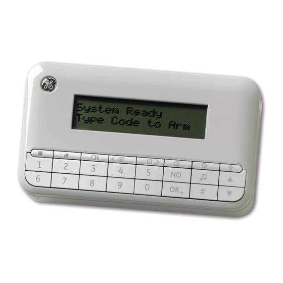
NetworX Version 3 Installation Manual Keypads Wireless keypad The wireless LCD keypad allows you to program the NetworX V3 system using a menu structure. There is also an option to use the wired keypad with the same functionality. Figure 3. Keypad. - Page 20 NetworX Version 3 Installation Manual The NetworX V3 keypad has the following key layout out-of-the-box: Figure 4. Default keypad layout. The four top-row keys with the blank keycaps can be replaced by the installer, as they are supplied with the keypad for this purpose. Figure 3 shows the keypad with the optional function keycaps placed in their default positions (factory setting).
- Page 21 NetworX Version 3 Installation Manual When in the menu: Press to scroll to the start of the LCD message. When in master mode: Disarm Press to disarm the system. Note: The Disarm key works in the master mode only, after the user code and the partition number have been entered.
-
Page 22: Lcd Icons
NetworX Version 3 Installation Manual LCD icons The LCD display for the NetworX V3 keypad consists of two separate sections, one for displaying 2 rows of 16 characters of alphanumeric data, and one for showing icons. The display section on the wireless keypad showing alphanumeric data is only turned ON while the user is operating the keypad, and turns OFF 30 seconds after the last key hit. - Page 23 NetworX Version 3 Installation Manual This icon is only available on the wireless keypad and flashing when the Battery low keypad battery is low. This icon flashes in case of an alarm condition. Alarm This icon is only available on the wireless keypad and indicates RF-link field strength.
- Page 24 NetworX Version 3 Installation Manual Blinking AC fault Battery low Blinking Blinking AC OK Battery low...
-
Page 25: Chapter A2 Installation Guidelines
Keep away from children. To replace the battery, please disconnect it and remove it from the holder. If required, replace with the GE Security BS127N lead batery only. Do not use a different type of batteries. Mounting •... -
Page 26: Wiring Guidelines
NetworX Version 3 Installation Manual Wiring guidelines The NetworX V3 has been designed, assembled and tested to meet current standards for safety, emission and immunity from environmental electrical and electromagnetic interference. Only a qualified electrician or other suitably trained and qualified person should attempt to wire this system to the mains or to the public telephone network. -
Page 27: Chapter A3 Installing A Basic System
NetworX Version 3 Installation Manual Chapter A3 Installing a basic system Installing the NetworX V3 CAUTION: Before installing the panel: • Ensure that the unit is mounted on a flat, solid, vertical surface so that the base will not flex or warp when the mounting screws/bolts are tightened. - Page 28 NetworX Version 3 Installation Manual When expanding the small system, switching to the large polycarbonate box may be required, since more modules cannot physically fit the smaller housing. Figure 6. Largel polycarbonate housing Mount the panel housing on the wall using mounting holes shown as items in Figures 5 and 6.
-
Page 29: Installing The Keypad
NetworX Version 3 Installation Manual Figure 7. Connecting the battery to the panel. Close the housing. Installing the keypad Mounting the wireless keypad Depending on the configuration, the wireless keypad can be mounted on the wall in a cradle or used as a portable device. -
Page 30: Mounting The Wired Keypad
Note: Any unauthorized opening of the battery compartment will cause tamper alarm in the system. Mounting the wired keypad There is also an option to use wired keypads with the NetworX V3 system. To install a wired keypad: Run the NetworX bus cable to the appropriate location on the wall. Insert the cable into the cable opening in the wired keypad's backplate. - Page 31 NetworX Version 3 Installation Manual Figure 10. Wired keypad connector block. At the panel side, run the NetworX bus wires through the ferrite (see Figure 11, position ), making one loop, and connect the wires to the standard NetworX bus contacts (see Figure 1, position ).
-
Page 32: Wireless Keypad Learning-In Procedure
NetworX Version 3 Installation Manual There is a slight difference in keypad reaction speed between the wired and wireless keypad, because the wireless keypad needs more time to communicate with the control panel. Please allow appropriate time to send data between the panel and the wireless keypad, especially during programming, when large amount of information is exchanged. -
Page 33: Installing The Wireless Sirens
NetworX Version 3 Installation Manual The keypad communicates with the panel and sends data entered in steps 3 to 8. The Learn-in Mode message displays briefly. The keypad is learned-in and displays the System Ready message. Important: You should not program zero-only strings (for example, "000") as values for SysID, KID1, KID2 nor Encryption Key, as it will make the keypad non-operational. - Page 34 NetworX Version 3 Installation Manual Figure 12. Wireless indoor siren Speaker Tamper 4x AA battery pack Tamper 9 V battery 9 V battery terminal (+) Siren PCB 9 V battery terminal (-) Siren driver (-) 4x AA battery pack (+) Siren driver (+) 4x AA battery pack (-) Open collector output (-)
- Page 35 NetworX Version 3 Installation Manual Open collector output (+) TX-7001-05-1 Wireless indoor siren specifications Power supply specifications Electronics Number and type of batteries 4 x AA size, 1.5 V, primary cell Battery capacity 5600 mAh Board operating voltage 2.1 V … 3.1 V Siren part Number and type of batteries 1 x 9V size block, primary cell...
- Page 36 NetworX Version 3 Installation Manual Figure 13. Wireless outdoor siren Siren PCB Tamper Speaker Tamper Beacon Open collector output 2 (+) for beacon 3X lithium battery pack Open collector output 2 (-) for beacon IO module power cable (black) Open collector output 1 (+) for speaker IO module power cable (blue) Open collector output 1 (-) for speaker...
- Page 37 NetworX Version 3 Installation Manual IO module power cable (red) IO module PCB To allow the IO module to control the output on the outdoor siren, you need to cut jumper 3 and then optionally 1 and/or 2. Jumper 3 is a start-up protection. Jumpers 1 and 2 are responsible for timer settings, and you can cut one of them or both, according to the table below.
-
Page 38: Installing The Wireless Sensors
NetworX Version 3 Installation Manual Installing the wireless sensors Mounting the sensors Select the appropriate location to place the sensor. For recommendations and rules regarding a correct placement of the particular sensor (motion sensor, door/window, smoke, etc.), see the sensor manual enclosed with the device you want to install. Fasten the sensor base to the wall. -
Page 39: Chapter A4 Programming Guidelines
Country codes The NetworX V3 has the ability to set different “country codes”. Each country code has specific default settings. When you start your system for the first time (see Powering up the system below) and select keypad defaults during the initial keypad setup, the respective country code is also set up automatically for the panel. -
Page 40: Powering Up The System
Continue using the keypad as normal. Note: When the NetworX V3 is powered up for the first time, only the single language selected during keypad installation is available. To toggle the user interface language, the available languages must be defined first... -
Page 41: Navigating The Menus
Changing a menu option The NetworX V3 has several editors that you can use to change the value of certain programmable menu options. You can change selection list entries, binary entries, phone numbers and text. This section describes how to change selection list entries, binary entries, numeric entries and phone numbers. -
Page 42: Changing Binary Entries
NetworX Version 3 Installation Manual • If the new value is invalid, the keypad beeps three times to reject the change and returns to the menu option. Press NO to cancel the change and return to the menu option. Changing binary entries Navigate with the keys to the relevant menu option and press OK. -
Page 43: Exiting The Menu System
Editing text Overview The NetworX V3 has a text editor that includes a word library. You can use this editor to change the text of certain programmable text options. -
Page 44: Example
NetworX Version 3 Installation Manual Navigate with the keys to the relevant menu option and press OK. Press OK to select the language you want to edit. The current text for the menu option is displayed, for example, Zone 2. Do one of the following: •... -
Page 45: Word Library
NetworX Version 3 Installation Manual Word library The word library is a predefined collection of words that speeds up text editing. As you type a character, the keypad automatically displays a matching word. The word library is enabled by default. For a complete list of words in the word library, see Appendix 6: Word library words. •... -
Page 46: Programming A Location
NetworX Version 3 Installation Manual of module numbers on page 261. The procedure for programming these devices is the same as for the control panel, except that the location will be for the module selected. Programming a location Note: Before programming the panel, the correct country code must be set in location 213 or through the installer menu, with This Keypad>Load Country Defaults menu option. -
Page 47: Chapter A5 Setting Up A Communicator
NetworX Version 3 Installation Manual Chapter A5 Setting up a communicator Reporting The NetworX system supports different modes of reporting events to multiple central stations. There are three phone numbers - each phone number has it own account code, protocol and events. The configured prefix is common to all three phone numbers. -
Page 48: Dual Reporting
NetworX Version 3 Installation Manual performs the sequence for the number of times specified in Dial Attempts or until it receives a kiss off. The same account code is used to report to all numbers. Events for phone number 1 are enabled by default and events for phone numbers 2 - 3 are disabled by default. -
Page 49: Split Reporting
NetworX Version 3 Installation Manual Level 1 Level 2 Value State Protocol Phone Number 1 Phone Number 2 Events Phone Number 1 – Alarms Enabled Phone Number 1 – Alarm Restores Enabled Phone Number 1 – Tampers and Restores Enabled Phone Number 2 –... -
Page 50: Section B Programming The System
NetworX Version 3 Installation Manual Section B Programming the system... -
Page 51: Chapter B1 Selecting The Programming Mode
Selecting the programming mode The NetworX V3 system allows to use two different programming modes — location-based programming or menu-based programming. In location-based programming you use locations and segments to set appropriate values. In menu-based programming you use a menu tree to enable/disable particular options or to set values. - Page 52 NetworX Version 3 Installation Manual Note: Recording and playback of voice messages (for example, for NX-535) cannot be performed with the NX-1048 location mode. You can record and play voice messages using the menu system only.
-
Page 53: Chapter B2 Programming The Control Panel
NetworX Version 3 Installation Manual Chapter B2 Programming the control panel Overview You must default the control panel before you begin to program the system. For more information on enrolling and defaulting, see Chapter B7 Enrolling modules. Programming inputs Figure 15. Inputs menu Zone Type Zones (1) Zone 1... - Page 54 NetworX Version 3 Installation Manual A zone may reside in any combination of partitions. A zone that resides in more than one partition becomes a common zone and is reported to its lowest partition number. A common zone is armed only when all the partitions that it belongs to are armed.
-
Page 55: Defining A Zone
NetworX Version 3 Installation Manual Bypass bypass when the “Group Bypass” command is entered at the keypad Keyswitch This zone type will arm/disarm the partition or partitions of the control panel where it is resident, Maintained as long as the zone state is changed from R to 2R (for example, the Door-Window Switch is opened or closed) and kept in this state. -
Page 56: Copying Zone Settings
NetworX Version 3 Installation Manual Scroll to the relevant language and press OK. The current name for zone is displayed, for example, Zone 1. Press to enter overwrite mode and press the keys 0 to 9 to insert new characters. Press OK to accept the changes. -
Page 57: Setting Swinger Count
NetworX Version 3 Installation Manual The keypad beeps once to confirm the change and returns to 24-hour. Scroll to Attributes>Swinger Zone>Yes and press OK. The keypad beeps once to confirm the change and returns to Swinger Zone. Set the value of Inputs>Swinger Count to 5. For more information see Setting swinger count below. -
Page 58: Programming Outputs
NetworX Version 3 Installation Manual Programming outputs Figure 16. Outputs menu Prog Outputs 1 (< Any Siren >) Event Alarms 2.2.1.1.1.1 2.2.1 2.2.1.1 2.2.1.1.1 Arm/Disarm 2.2.1.1.1.2 Outputs 2 - 4 Communications 2.2.1.1.1.3 Same as above Keypads 2.2.1.1.1.4 Sirens 2.2.1.1.1.5 Tamper/Fault 2.2.1.1.1.6 Tests 2.2.1.1.1.7... -
Page 59: Configuring The Internal Siren
NetworX Version 3 Installation Manual The keypad beeps once to confirm the change and returns to Time Unit. Scroll to Time and press OK. Select 15 min. and press OK to accept the changes. The keypad beeps once to confirm the change and returns to Time. Table 16. -
Page 60: Programming The Keypad Sounder
NetworX Version 3 Installation Manual Navigate with the keys to Control Panel>Outputs>Internal Siren>Short Blast On and press OK. Scroll to Keyswitch Arming>Yes and press OK. The keypad beeps once to confirm the change and returns to Keyswitch Arming. Programming the keypad sounder You can specify conditions and/or events that activate the keypad sounder. - Page 61 NetworX Version 3 Installation Manual Enter the new code and press OK. Enter the new code and press OK. The keypad beeps once to confirm the change and returns to Code. Scroll to Authority>Arm Only>Yes and press OK. The keypad beeps once to confirm the change and returns to Arm Only. Navigate with the keys to Partitions and press OK.
-
Page 62: Setting Communication Options
NetworX Version 3 Installation Manual Setting communication options Figure 18. Communication menu Phone Numbers Central Station 2.4.1.1.1 2.4.1.1.1.1 2.4.1 2.4.1.1 2.4.1.1.1.2 Phone Numbers 2 - 6 2.4.1.1.1.3 Same as above 2.4.1.1.1.4 2.4.1.1.1.5 Alarms Events Arm/Disarm/Alarm 2.4.1.1.1.4.1.1 2.4.1.1.1.6 2.4.1.1.1.4.1 Alarm Restores 2.4.1.1.1.4.1.2 Opening/Closing 2.4.1.1.1.4.1.3... -
Page 63: Defining Communication With A Central Station
NetworX Version 3 Installation Manual Figure 19. Report codes menu Zone Types (1) Day Zone Event Code Report Codes 2.4.4.3.1.1.1 2.4.4.3.1.1 2.4.4.3 2.4.4.3.1 SIA Code 2.4.4.3.1.1.2 Zone Types 2 - 0 CID Code Same as above 2.4.4.3.1.1.3 (1) Partition 1 Partition Reports Restore 2.4.4.3.2... -
Page 64: Defining Communication With A Mobile Phone
NetworX Version 3 Installation Manual Navigate with the keys to Control Panel>Communications>Central Station and press OK. Scroll to Phone numbers>Phone Number 1>Dial Attempts and press OK. Select 3 and press OK. The keypad beeps once to confirm the change and returns to Dial Attempts. Defining communication with a mobile phone You can also treat a telephone (for example, your mobile phone) as a central station. -
Page 65: Configuring The System Autotest
NetworX Version 3 Installation Manual Configuring the system autotest The autotest is run at configured intervals to ensure communication between the control panel and central station or the control panel and up/download software is functioning correctly. The following example sets the system autotest to run every Friday at 12.45, assuming that today is Wednesday. Navigate with the keys to Control Panel>Communications>Autotest>Hours/Days?>Days and press OK. -
Page 66: Configuring Partitions
NetworX Version 3 Installation Manual Configuring partitions Figure 20. Partitions menu Entry Time (1) Partition 1 Timers 2.5.1 2.5.1.1 2.5.1.1.1 Exit Time 2.5.1.1.2 Partitions 2 Entry Time 2.5.1.1.3 Same as above Exit Time 2.5.1.1.4 Quick Arm 2.5.1.2 Feature Select 2.5.1.2.1 Arming 2.5.1.2.1.1 Re-exit... -
Page 67: Configuring A Partition
NetworX Version 3 Installation Manual Configuring a partition You can set partition features including arming and bypassing options. You can also enable life safety keys for the partition keypads. The following example allows the system to be armed silently according to the auto-arm schedule, and enables the personal alarm combination keys so they activate a personal attack alarm when pressed. -
Page 68: Configuring The System
NetworX Version 3 Installation Manual Configuring the system Figure 21. System settings menu Timers Zones Fire Verification Time 2.6.1.1.1 2.6.1 2.6.1.1 Zone Act. Unit 2.6.1.1.2 Zone ctivity Monitor 2.6.1.1.3 Cross Zone Timer 2.6.1.1.4 Power Dynamic Batt Test 2.6.1.2.1 2.6.1.2 AC Failure Rprt Delay 2.6.1.2.2 Power Up Delay 2.6.1.2.3... -
Page 69: Configuring System Features
NetworX Version 3 Installation Manual Enter 5 and press OK. The keypad beeps once to confirm the change and returns to Internal Siren Timeout. Configuring system features You can specify various system features, enable the tests that can be performed on the control panel and set clock options. -
Page 70: Setting Up Schedules
NetworX Version 3 Installation Manual menu. Select Installer Menu>Maintenance Mode>Advanced Menu>Enabled and press OK. Then select Installer Menu>Control Panel>Arm Schedules. Note: If reports are sent, the user code will be 97 in logs and reports. Note: If an alarm happens during the period of time when the system is automatically armed, the system will not automatically disarm. - Page 71 NetworX Version 3 Installation Manual Location Term Definition 2.1.1.1.3 Partitions A menu entry that lists the partitions assigned to the selected zone. The selected zone can trigger an event on these partitions. A zone may reside in any combination of partitions. A zone that resides in more than one partition becomes a common zone and is reported to its lowest partition number.
- Page 72 NetworX Version 3 Installation Manual Location Term Definition 2.1.3.1.1.7 Entry Guard A zone type that reduces false alarms. If an armed entry guard zone is opened, the keypad sounder activates and the entry delay starts before creating an alarm. This can be programmed as a zone type.
- Page 73 NetworX Version 3 Installation Manual Location Term Definition option is visible only if the Keyswitch input type option is enabled. 2.1.3.1.3.11 Req. To Exit A zone characteristic that enables the zone to act as a request to exit input. 2.1.3.1.3.12 Holdup A zone characteristic that enables the zone to act as a holdup zone.
- Page 74 NetworX Version 3 Installation Manual Location Term Definition 2.1.3.1.5.4 Listen-in A menu option that sends a report to the central station indicating that a listen-in session must be started. In order to use listen-in, a NX-534E listen-in module must be installed and a microphone must be connected. When an alarm is generated and reported, the central station can listen to what is happening on the premises.
- Page 75 NetworX Version 3 Installation Manual Location Term Definition 2.2.1.1.4 Partitions A menu entry that lists the partitions assigned to the selected output. The selected output can be triggered by an event on these partitions. A zone may reside in any combination of partitions. A zone that resides in more than one partition becomes a common zone and is reported to its lowest partition number.
- Page 76 NetworX Version 3 Installation Manual Location Term Definition 2.2.2.2.1 Arming A menu option that causes the internal sounder to blast when the system arms. 2.2.2.2.2 Exit Delay Expired A menu option that causes the internal sounder to blast when the exit time expires. 2.2.2.2.3 Closing Kissoff A menu option that causes the internal sounder to blast...
- Page 77 NetworX Version 3 Installation Manual Location Term Definition A Codes menu entry that groups installer code options. 2.3.2.1 Code A menu option that sets the user code. This is a series of four or six numbers that allows access to the system. 2.3.2.2 Authority A menu entry that groups access options.
- Page 78 NetworX Version 3 Installation Manual Location Term Definition 2.3.5 User Auth for Progrm. A menu option specifying that user authorisation is required in order to enter program mode. Communications A menu entry that groups options for communication between the control panel and the up/download software or central stations.
- Page 79 NetworX Version 3 Installation Manual Location Term Definition the selected phone number. 2.4.1.1.1.6.1.1 Alarms A menu option that sends a report to the selected phone number when an alarm occurs. 2.4.1.1.1.6.1.2 Alarm Restores A menu option that sends a report to the selected phone number when the alarm has been restored after an alarm.
- Page 80 NetworX Version 3 Installation Manual Location Term Definition 2.4.1.1.1.6.4 Communications A menu entry that groups together the communication events that are reported to the selected phone number. 2.4.1.1.1.6.4.1 Fail to Communicate A menu option that reports a fail to communicate event to the selected phone number.
- Page 81 NetworX Version 3 Installation Manual Location Term Definition 2.4.2.5 Answer Machine Defeat A menu entry used to defeat an answering machine. If two- call Answer Machine Defeat AMD is enabled, two telephone calls are required to defeat the answering machine. On the first call, the phone rings once or twice.
- Page 82 NetworX Version 3 Installation Manual Location Term Definition is performed. 2.4.3.5 Time Since Test A menu option that sets the length of time since the last autotest. It controls when the next autotest report is sent to the central station. 2.4.4 Reporting A menu entry that groups reporting options.
- Page 83 NetworX Version 3 Installation Manual Location Term Definition 2.4.4.2.1.4 RF Sensor Lost A menu option that sends a report to the central station, when an RF sensor is missing. RF sensors send out supervision signals every 15 or 64 minutes, depending on the frequency. An RF receiver must receive these signals within a specified time window.
- Page 84 NetworX Version 3 Installation Manual Location Term Definition 2.4.4.2.6 First to Open/Last to Close A menu option that sends a report to the central station stating when the system opened and closed. This option can only be used in a multi-partitioned system. A report is sent stating the first partition opened.
- Page 85 NetworX Version 3 Installation Manual Location Term Definition threatened and forced to disarm the system. A duress code is entered to disarm the system as normal and a duress alarm is activated. 2.4.4.3.3.2 Keypad Aux 1 (Fire) A menu entry that groups the report codes sent for the keypad aux 1 (fire) event.
- Page 86 NetworX Version 3 Installation Manual Location Term Definition 2.4.4.3.6.3 Cancel A menu option that enables cancel reporting. A cancel report is sent to the central station when the system is disarmed (within the time specified by the dialer delay) after an alarm. 2.4.4.3.6.4 Recent Closing A menu option that sends a report to the central station if...
- Page 87 NetworX Version 3 Installation Manual Location Term Definition 2.5.1.1.3 Entry Time 2 A menu option that sets the time within which the user must disarm the partition before a full alarm occurs. This time can be between 10 and 255 seconds. 2.5.1.1.4 Exit Time 2 A menu option that sets the time within which the user...
- Page 88 NetworX Version 3 Installation Manual Location Term Definition 2.5.1.2.1.7 Instant Stay Toggle A menu option that enables a toggled setting of the Arm Stay (F4) function key (toggling between Stay and Instant mode for a partition). When this option is enabled, pressing the F4 key once arms the system in the Stay mode.
- Page 89 NetworX Version 3 Installation Manual Location Term Definition 2.5.1.2.2.4 Medical/Aux 2 A menu option that activates a key with the Medical Alarm function assigned, for all the keypads in the selected partition (see This Keypad>Function Keys option description). When this option is enabled and the Medical Alarm key is pressed at the keypad, a medical alarm is generated.
- Page 90 NetworX Version 3 Installation Manual Location Term Definition 2.5.1.2.4.2 Tamper if Zone Lost A menu option that sends a report to the central station when a wireless zone sensor is lost and activates a tamper alarm. Different reports are sent depending on the system status.
- Page 91 This provides a completely wireless alarm system. 2.6.2.1.2 Box Tamper A menu option that enables the box tamper switch on the control panel. The NetworX V3 has an input for a normally closed tamper switch. When opened, a box tamper is reported as an event. 2.6.2.1.3...
- Page 92 NetworX Version 3 Installation Manual Location Term Definition 2.6.2.1.7 Immediate Zone Restore A menu option that sets the way zones are restored. When it is On, the zones restore immediately. In this case all the alarms and restores are sent as they occur even in case of multiple alarms.
- Page 93 NetworX Version 3 Installation Manual Location Term Definition will be the one that says "Alarm Memory" with the "Alarm" message flashing. If this option is disabled, all tripped zones will be displayed as well as all bypassed zones. A menu option that prevents a single, non-zone reportable 2.6.2.4.5 Log Protection event to fill up the event memory.
-
Page 94: Control Panel Programming Locations
NetworX Version 3 Installation Manual Location Term Definition 2.7.3.2 Closing/Autoarm A menu option that sets the time after which the partitions selected in Partitions Autoarming start to arm automatically. Users with arm only after closing rights can arm the partitions selected in Partitions Opening only after this time. -
Page 95: Reporting Events To Phone Number 1
NetworX V3 to stop trying to communicate after the designated number of attempts have been made to phone N°1. If a “2” is programmed in this segment, it will cause the NetworX V3 to make the dial attempts in increments of two. The first two attempts will be made to phone N°1, the next two attempts to phone N°2, then repeating until the total number of attempts designated in Segment 1... -
Page 96: Telephone Number 2
NetworX Version 3 Installation Manual Zone bypass and bypass restores Zone trouble and trouble restores Power fail (AC failure), low battery, power restore (AC restore) , and low battery bestore Bell cut, bell cut restore, telephone line restore Test reports Start and end programming, download complete and log full Segment 2 Zone and box tamper... -
Page 97: Reporting Events To Phone Number 2
NetworX V3 to stop trying to communicate after the designated number of attempts have been made to phone N°2. If a “2” is programmed in this segment, it will cause the NetworX V3 to make the dial attempts in increments of two. The first two attempts will be made to phone N°2, the next two attempts to phone N°1, then repeating until the total number of attempts designated in segment 1 is... -
Page 98: Telephone Number 3
NetworX Version 3 Installation Manual LOCATION 10 - EVENTS REPORTED TO PHONE N° 2 (2 segments of feature selection data) Segment 1 Alarms Opening and closings Zone bypass and bypass restores Zone trouble and trouble restores Power fail (AC failure), low battery, power restore (AC restore) , and low battery restore Bell cut, bell cut restore, telephone line restore Test reports... -
Page 99: Reporting Events To Phone Number 3
NetworX V3 to stop trying to communicate after the designated number of attempts have been made to phone N°3. If a “2” is programmed in this segment, it will cause the NetworX V3 to make the dial attempts in increments of two. The first two attempts will be made to phone N°3, the next two attempts to phone N°2, then repeating until the total number of attempts designated in segment 1... -
Page 100: Special Formats
NetworX Version 3 Installation Manual at the factory default of “0”. If you want dual or split reporting, and the split is based on partition, then location 16 should be programmed to “0” and location 17 should be used to select those partitions that are to be reported to phone N°3. -
Page 101: Download Parameters
Location 20 contains the number of rings to answer for a download. Enter a number from “0” (disabled) to “15”. Factory default is “8”, so the NetworX V3 will answer after 8 rings. LOCATION 21 - DOWNLOAD CONTROL (1 segment, feature selection data) Location 21 contains the feature selections to control download sessions. -
Page 102: Feature And Report Selections (For Partition 1)
NetworX Version 3 Installation Manual On: locks out download section. (If “On”, locations 19-22 cannot be viewed from the keypad; can only be viewed from the keypad when “Off”.) On: enables call-back at auto test interval LOCATION 22 - DOWNLOAD CALL BACK NUMBER (20 segments, numerical data) If a telephone number is programmed into this location, and “Require Call-back”... -
Page 103: Entry/Exit Timers
NetworX Version 3 Installation Manual Segment 3 On: enables opening and closing reports On: enables zone bypass reporting On: enables zone restore reporting On: enables zone trouble reporting On: enables zone tamper reporting On: enables the cancel reporting On: enables the recent closing report On: enables the exit error report Segment 4 On: enables late to close / early to open reporting... -
Page 104: Zone Configurations And Partition Selection
NetworX Version 3 Installation Manual Segment 5 Reserved Segment 6 Reserved Zone configurations and partition selection DEFAULT ZONE CONFIGURATIONS Zones can be programmed to be one of thirty different zone configurations (zone types). The default zone configurations are listed below. Programming locations 110-169 can customise all zone configurations. - Page 105 NetworX Version 3 Installation Manual INSTANT ENTRY GUARD This zone creates an instant alarm whenever it is tripped and the zone is timed. It will start an entry delay time 2 if it is tripped, provided that the system is armed and the stay/instant mode is on. ENTRY/EXIT DELAY 1 WITH GROUP BYPASS ENABLED A trip will start entry delay 1.
- Page 106 NetworX Version 3 Installation Manual activity time is reached without a change of state (see location 40, segment 11 and locations 110-169). INSTANT ZONE WITH END OF LINE RESISTOR DEFEAT This zone creates an instant alarm whenever the system is armed. When the loop is closed, the zone is ready.
- Page 107 NetworX Version 3 Installation Manual LOCATION 29 - ZONES 17-24 CONFIGURATION GROUP (8 segments, numerical data) Location 29 contains the configuration group (zone type) for zones 17-24. Segment 1 is for zone 17, segment 8 is for zone 24. You will find the default configurations in the table above. LOCATION 30 - PARTITION SELECT, ZONES 17-24 (8 segments, feature selection data) Location 30 is used to select the partition(s) in which zones 17-24 reside.
-
Page 108: General Options
On: if siren sounds during a “Cross Zone” verification time On: if siren sounds for a zone or box tamper On: if siren* blasts 1 time for keyswitch or wireless arming; 2 times for disarming * BELL output only on NetworX V3... - Page 109 On: if manual communicator test is performed during self test function On: if Box Tamper terminals on the control panel are enabled * BELL output only on NetworX V3 Segment 3 On: if box tamper report is enabled...
- Page 110 NetworX Version 3 Installation Manual (*) Note: This feature is only used when the GSM module is enrolled by the panel and if the GSM module is used as backup (GSM voice channel) for the PSTN dialer of the panel. Also telephone line monitoring needs to be enabled in location 40.
- Page 111 NetworX Version 3 Installation Manual arm/disarm codes and the installer code are 6 digits. If this option is enabled, the default user 1 code is [1]-[2]-[3]-[4]-[5]-[6]. Note: If you enable this option, verify that the installer code is a six-digit code before you exit from programming On: requires code entry for the perform callback download function and the answer incoming call for download function...
-
Page 112: Programming The Outputs
NetworX Version 3 Installation Manual Programming the outputs LOCATION 45 - AUXILIARY OUTPUT 1-2 PARTITION SELECTION (2 segments, feature selection data) Location 45 is used to select the partition(s) in which the events must occur before the output (relay) will activate. Location 45 has 2 segments. Segment 1 corresponds to output 1, and segment 2 corresponds to output 2. -
Page 113: Setup For Auto-Test, Auto-Arm And Opening/Closing Times
NetworX Version 3 Installation Manual Table 17. Auxiliary output event selection Data Event Data Event Burglary alarm Open period Fire alarm Closed period 24 hour alarm Listen-in Trouble alarm Line seizure Tamper alarm Reserved Yelping siren Fail to communicate Steady siren Telephone line fault Any siren Program mode... - Page 114 LOCATION 52 - OPENING TIME/AUTOMATIC DISARMING TIME (2 segments, numerical data) Location 52 contains the time (in 24 hour format) when the NetworX V3 will enable the disarm capability for codes designated as ‘arm only after closing’. This time is only valid on those days programmed in location 54.
-
Page 115: Communicator Codes For Slow Speed Formats Only
NetworX Version 3 Installation Manual warning timer, the zone will automatically be bypassed. If the zone restores, it will be unbypassed and active in the system. Segment 1-4 Auto arming on Sunday Auto arming on Monday Auto arming on Tuesday Auto arming on Wednesday Auto arming on Thursday Auto arming on Friday... - Page 116 NetworX Version 3 Installation Manual LOCATION 58 - TAMPER COMMUNICATOR CODE, SLOW SPEED FORMATS (4 segments, numerical data) Location 58 contains the event code for a zone “Tamper” with a 4+2 and 3+1 format. For a 4+2 format, the digit programmed in this location will be sent as the tens digit of the tamper event code. The zone ID will always be reported as the ones digit of the zone number (e.g.
- Page 117 NetworX Version 3 Installation Manual code. The zone ID will always be reported as the ones digit of the zone number (e.g. zone 12 = 2, zone 44 = 4). This location contains 4 segments. Any segment left as “0” will follow the Segment 1 selection. Segment 1 Partition 1 “Sensor Missing Code”...
- Page 118 NetworX Version 3 Installation Manual LOCATION 66 - KEYPAD MULTIPLE CODE ENTRY TAMPER COMMUNICATOR CODE, SLOW SPEED FORMATS ONLY (2 segments, numerical data) Location 66 contains the tens and ones digits that will be sent for a 4+2 and 3+1 format if the keypad “Multiple Code Entry”...
- Page 119 NetworX Version 3 Installation Manual LOCATION 70 - AUX POWER OVERCURRENT/ AUX POWER OVERCURRENT RESTORE COMMUNICATOR CODES, SLOW SPEED FORMATS ONLY (4 segments, numerical data) Location 70 contains the tens and ones digits for a 4+2 and 3+1 format that will be sent if “Aux Power Overcurrent Reporting”...
- Page 120 NetworX Version 3 Installation Manual LOCATION 75 - FAIL TO COMMUNICATE COMMUNICATOR CODE, SLOW SPEED FORMATS ONLY (2 segments, numerical data) Location 75 contains the tens and ones digits for a 4+2 and 3+1 format that will be sent if the “Fail To Communicate Reporting”...
- Page 121 NetworX Version 3 Installation Manual If you need to report openings and closings with a unique code per user, Contact ID or SIA format must be used. Segment 1 Closing code for partition 1 Segment 2 Closing code for partition 2 Segment 3 Closing code for partition 3 Segment 4...
-
Page 122: Programming Partition Parameters
NetworX Version 3 Installation Manual Location 82 contains the tens and ones digits for a 4+2 and 3+1 format that will be sent if “End Downloading Reporting” is enabled. Segment 1 and 2 are reserved. Segment 3 contains the tens digit of the “End Download Reporting”. - Page 123 NetworX Version 3 Installation Manual LOCATION 88 - ACCOUNT CODE FOR PARTITION 1 (6 segments, numerical data) Location 88 contains the account code that is sent when partition 1 is reported. If location 88 is left unprogrammed (all “10”s), then the account code corresponding to the phone number that is dialled will be used.
- Page 124 NetworX Version 3 Installation Manual LOCATION 93 - PARTITION 3 FEATURE AND REPORTING SELECTIONS (5 segments, feature selection data) Location 93 is used to enable certain features that the user can access or see from the keypad of the system. In addition, certain communicator reports are enabled in this location. Each of these features can be enabled by partition.
-
Page 125: Programming Zone Configuration Groups
NetworX Version 3 Installation Manual LOCATION 97 - PARTITION 4 ENTRY EXIT TIMERS (6 segments, numerical data) Location 97 is used to enter the entry and exit times in seconds. There are 2 separate entry and exit times. Valid entries are 10-255 seconds. If all the segments are “0”, the entry and exit times for partition 1 will be used. - Page 126 NetworX Version 3 Installation Manual On: if configuration group is force armable On: if configuration group is entry guard Segment 3 On: enables Fast Loop Response. (50mS) - Off= 500mS On: enables Double End Of Line Tamper zone. (Mainly used for tamper on wireless zones) On: enables Trouble Reporting zone.
- Page 127 NetworX Version 3 Installation Manual LOCATION 115 - CONFIGURATION GROUP 3 CHARACTERISTIC SELECT (5 segments, feature selection data) Use the “Configuration Group Characteristic Selections” described in Location 111. LOCATION 116 - CONFIGURATION GROUP 4 ALARM EVENT CODE (1 segment, numerical data) Location 116 contains the event code that is sent for a Contact ID or SIA report.
- Page 128 NetworX Version 3 Installation Manual This location is not used for slow speed formats (like 4+2 and 3+1). This location may also contain the alarm report code for the Robofon format (value 00-99). LOCATION 121 - CONFIGURATION GROUP 6 CHARACTERISTIC SELECT (5 segments, feature selection data) Use the “Configuration Group Characteristic Selections”...
- Page 129 NetworX Version 3 Installation Manual LOCATION 126 - CONFIGURATION GROUP 9 ALARM EVENT CODE (1 segment, numerical data) Location 126 contains the event code that is sent for a Contact ID or SIA report. The desired event code should be chosen from the Table 38 or Table 39 in Appendix 1. The zone ID will be the zone that is in alarm.
- Page 130 NetworX Version 3 Installation Manual LOCATION 131 - CONFIGURATION GROUP 11 CHARACTERISTIC SELECT (5 segments, feature selection data) Use the “Configuration Group Characteristic Selections” described in Location 111. LOCATION 132 - CONFIGURATION GROUP 12 ALARM EVENT CODE (1 segment, numerical data) Location 132 contains the event code that is sent for a Contact ID or SIA report.
- Page 131 NetworX Version 3 Installation Manual LOCATION 136 - CONFIGURATION GROUP 14 ALARM EVENT CODE (1 segment, numerical data) Location 136 contains the event code that is sent for a Contact ID or SIA report. The desired event code should be chosen from the Table 38 or Table 39 in Appendix 1. The zone ID will be the zone that is in alarm.
- Page 132 NetworX Version 3 Installation Manual LOCATION 141 - CONFIGURATION GROUP 16 CHARACTERISTIC SELECT (5 segments, feature selection data) Use the “Configuration Group Characteristic Selections” described in Location 111. LOCATION 142 - CONFIGURATION GROUP 17 ALARM EVENT CODE (1 segment, numerical data) Location 142 contains the event code that is sent for a Contact ID or SIA report.
- Page 133 NetworX Version 3 Installation Manual This location is not used for slow speed formats (like 4+2 and 3+1). This location may also contain the alarm report code for the Robofon format (value 00-99). LOCATION 147 - CONFIGURATION GROUP 19 CHARACTERISTIC SELECT (5 segments, feature selection data) Use the “Configuration Group Characteristic Selections”...
- Page 134 NetworX Version 3 Installation Manual LOCATION 152 - CONFIGURATION GROUP 22 ALARM EVENT CODE (1 segment, numerical data) Location 152 contains the event code that is sent for a Contact ID or SIA report. The desired event code should be chosen from the Table 38 or Table 39 in Appendix 1. The zone ID will be the zone that is in alarm.
- Page 135 NetworX Version 3 Installation Manual LOCATION 157 - CONFIGURATION GROUP 24 CHARACTERISTIC SELECT (5 segments, feature selection data) Use the “Configuration Group Characteristic Selections” described in Location 111. LOCATION 158 - CONFIGURATION GROUP 25 ALARM EVENT CODE (1 segment, numerical data) Location 158 contains the event code that is sent for a Contact ID or SIA report.
- Page 136 NetworX Version 3 Installation Manual This location is not used for slow speed formats (like 4+2 and 3+1). This location may also contain the alarm report code for the Robofon format (value 00-99). LOCATION 163 - CONFIGURATION GROUP 27 CHARACTERISTIC SELECT (5 segments, feature selection data) Use the “Configuration Group Characteristic Selections”...
- Page 137 NetworX Version 3 Installation Manual LOCATION 168 - CONFIGURATION GROUP 30 ALARM EVENT CODE (1 segment, numerical data) Location 168 contains the event code that is sent for a Contact ID or SIA report. The desired event code should be chosen from the Table 38 or Table 39 in Appendix 1. The zone ID will be the zone that is in alarm.
- Page 138 NetworX Version 3 Installation Manual LOCATION 213 – PROGRAMMING THE COUNTRY CODE (1 segment, numerical data) The NetworX system has the ability to set different “country codes”. Each country code has specific default settings. Before start programming the system, it is important to select the country code that is required (see table below).
-
Page 139: Networx V3 Location-Programming Worksheets
NetworX Version 3 Installation Manual NetworX V3 location-programming worksheets Factory defaults for NetworX V3 are in bold italic text. These defaults are for the country code 2 (Belgium/Poland). Description Default Programming data PHONE 1 14-14-14-14-14-14-14-14-14- 14-14-14-14-14-14-14-14-14- 14-14 10 – 10 – 10 – 10 – 10 – 10... - Page 140 NetworX Version 3 Installation Manual Partition 2 Partition 3 Partition 4 PHONE 3 14-14-14-14-14-14-14-14-14-14- 14-14-14-14-14-14-14-14-14-14 PHONE 3, ACCOUNT CODE 10 – 10 – 10 – 10 – 10 – 10 PHONE 3, REPORTING FORMAT PHONE 3, DIAL ATTEMPTS BACKUP CONTROL PHONE 3, SELECTING EVENTS TO REPORT TO PHONE 3 Segment 1 (Circle Numbers To Program) Segment 2 (Circle Numbers To Program)
- Page 141 NetworX Version 3 Installation Manual Reserved Requires callback before downloading Shutdown control panel Lock out local programming Lock out communicator programming Lock out download section Enables callback at autotest interval CALLBACK PHONE NUMBER 14-14-14-14-14-14-14-14-14- 14-14-14-14-14-14-14-14-14- 14-14 PARTITION 1, FEATURE SELECTION Segment 1 Segment 2 Segment 3...
- Page 142 NetworX Version 3 Installation Manual ZONES 9-16, CONFIGURATION GROUPS 6-6-6-6-6-6-6-6 ZONES 9-16, PARTITION SELECTION (Segment 1=Zone 9 thru Segment 8=Zone 16) Segments Partition 1 Partition 2 Partition 3 Partition 4 6-6-6-6-6-6-6-6 ZONES 17-24, CONFIGURATION GROUPS ZONES 17-24, PARTITION SELECTION (Segment 1=Zone 17 thru Segment 8=Zone 24) Segments Partition 1 Partition 2...
- Page 143 NetworX Version 3 Installation Manual Battery missing test performed every 12 seconds Manual bell test performed during self-test function (BELL output, I/O and relays) Manual communicator test performed during self-test function Box tamper enabled Segment 3 (Circle Numbers To Program) Box Tamper report enabled AC Fail report enabled Low Battery report enabled...
- Page 144 NetworX Version 3 Installation Manual Keypad sounds upon AC Power Failure Keypad sounds upon Low Battery Detection Keypad sounds during Cross Zone Trip Time Keypad sounds for Tamper Alarm Keypad sounds for Emergency keys Keypad sounds for Expander Trouble SYSTEM TIMERS Segment 1 Dynamic Battery Test duration (0-30 minutes) Segment 2...
- Page 145 NetworX Version 3 Installation Manual Segment 2 (Circle Numbers To Program) Enables “Go To Program Code” for partition #1. Enables “Go To Program Code” for partition #2. Enables “Go To Program Code” for partition #3. Enables “Go To Program Code” for partition #4. DURESS CODE 15-15-15-15-15- AUXILIARY OUTPUTS 1-2 PARTITION SELECTION...
- Page 146 NetworX Version 3 Installation Manual Segment 2 Program the minutes after hour of closing / auto arming time DAYS OF THE WEEK WHEN “ARM ONLY AFTER CLOSE” WILL ARM/DISARM IN PARTITIONS 1-4 Segments Sunday Monday Tuesday Wednesday Thursday Friday Saturday Reserved DAYS OF THE WEEK WHEN “AUTO ARMING”...
- Page 147 NetworX Version 3 Installation Manual Segment 4 Partition 4 sensor low battery code SENSOR MISSING COMMUNICATOR CODE, SLOW SPEED FORMATS ONLY Segment 1 Partition 1 sensor missing code Segment 2 Partition 2 sensor missing code Segment 3 Partition 3 sensor missing code Segment 4 Partition 4 sensor missing code COMMUNICATOR CODES FOR SLOW SPEED FORMATS ONLY...
- Page 148 NetworX Version 3 Installation Manual Auxiliary 1 Enables silent auto arm Cancel Auxiliary 2 Enables automatic instant (entry/exit) Recent Closing Multi Keypress Tamper Final set door Exit Error Segment 4 Segment 5 Late to close/early to open Disables auto bypassing of force armable zones Auto arm in stay mode Reserved Enables instant night...
- Page 149 NetworX Version 3 Installation Manual PARTITION 4, ACCOUNT CODE 10-10-10-10-10- PARTITION 4, FEATURE SELECTION Segment 1 Segment 2 Segment 3 Quick Arm LED extinguish enable Open/Close Re-Exit Require user code for bypassing Bypass zones Auto Bypass (interior) Bypass sounder alert Restore Silent Panic AC power/ low battery sounder alert...
- Page 150 NetworX Version 3 Installation Manual Zone acts as request to exit input Reserved Zone acts as acces control zone Reserved Segment 5 (Circle Numbers To Program) Reserved Note: The defaults listed in the odd-numbered locations below represent the five segments of each of those locations. Use the five segment charts from location 111 to understand these defaults.
- Page 151 NetworX Version 3 Installation Manual CONFIGURATION GROUP 24 ALARM EVENT CODE CONFIGURATION GROUP 24 CHARACTERISTIC SELECT 0-1245-25678 CONFIGURATION GROUP 25 ALARM EVENT CODE CONFIGURATION GROUP 25 CHARACTERISTIC SELECT 45-1245-25678 CONFIGURATION GROUP 26 ALARM EVENT CODE CONFIGURATION GROUP 26 CHARACTERISTIC SELECT 248-125-2 CONFIGURATION GROUP 27 ALARM EVENT CODE CONFIGURATION GROUP 27 CHARACTERISTIC SELECT...
-
Page 152: Chapter B3 Programming The Nx-1048 Keypad
NetworX Version 3 Installation Manual Chapter B3 Programming the NX-1048 keypad Overview Each NX-1048 keypad has a sounder and an LCD display that displays messages in a number of possible languages. Each NX-1048 keypad must be enrolled, defaulted to the country settings for the selected country and defaulted to the factory defaults before starting to program the system. - Page 153 NetworX Version 3 Installation Manual Figure 23. NX-1048 keypad menu Keypad Number Partition Nbr Keypad Features 3.3.1 Case Tamper Silent Keypad 3.3.2 Ding-Dong Chime 3.3.3 5 sec silence 3.3.4 Armed Zone Info 3.3.5 Beep on Panics 3.3.6 Master keypad 3.3.7 Service Message 3.3.8 Custom Message...
-
Page 154: Configuring The Nx-1048 Keypad Features
NetworX Version 3 Installation Manual Configuring the NX-1048 keypad features General options You can configure the LCD display, the keypad sounder and combination keys. The following example configures the keypad so that all codes are displayed as stars rather than in digits. It also configures the keypad sounder to beep when a wireless receiver does not report within the supervision window. - Page 155 NetworX Version 3 Installation Manual entering codes. The way the functions actually work depends on other system settings, for example the Arm Away function works as a single-button shortcut only in the single-partition mode if the Installer Menu>Control Panel>Partition Settings>Partition 1>Feature Select>Arming>Quick Arm menu option was set.
- Page 156 NetworX Version 3 Installation Manual The Enter Zone No. prompt displays. Type the zone number and press OK. Repeat this action for subsequent zones you want to bypass. To remove a zone from the bypassed zone set enter its number again. To partarm the system with the selected zones bypassed, enter the user code.
-
Page 157: Setting Up The Tamper Switch
NetworX Version 3 Installation Manual Setting up the tamper switch The wireless keypad has a pry-off switch. The installer decides how the keypad behaves whenever removed from its wall mounting plate. The option Always Tamper actually fixes the wireless keypad to the wall just like a wired one, while disabling this option renders the keypad fully portable within the reach of the RF link. - Page 158 NetworX Version 3 Installation Manual Backlight battery replacement Push the battery compartment cover in a direction indicated by the arrow symbol on the cover. Open the backlight battery compartment and replace batteries. Operating battery replacement The master user is allowed to perform the operating battery replacement according to the following procedure.
- Page 159 NetworX Version 3 Installation Manual Navigate with the keys to Change Batteries and press OK. Note, that Change Batteries option in User Menu is available only when keypad partitions are disarmed and when the This Keypad>Keypad Features>Battery Change Allowed menu option (in the Installer Menu) is set to Yes.
-
Page 160: Master Mode
NetworX Version 3 Installation Manual After replacing batteries, you have to close the battery compartment in 30 seconds. If "Type # to finish" message is displayed, press the # key to restore normal keypad operation. CAUTION: Batteries can explode or cause burns when recharged, incorrectly (dis)assembled, or exposed to fire or high temperatures. -
Page 161: Assigning X-10 Devices
NetworX Version 3 Installation Manual • Select Yes to set the keypad as a master keypad by default. • Select No to set the keypad as a single-partition keypad by default. Press OK to save the setting. The keypad beeps once to confirm the change and returns to Master Keypad. Assigning X-10 devices The keypad can be used to activate selected X-10 devices. -
Page 162: Setting Installer Messages
NetworX Version 3 Installation Manual Scroll to Language 2 and press OK. Use the keys to select Français and press OK. The keypad returns to Set KP Language. Repeat these steps to set other languages. Setting installer messages Up to four messages can be displayed on the LCD when the keypad is idle or when it times out from a menu. - Page 163 NetworX Version 3 Installation Manual Partition Settings and System Settings groups of the Control Panel menu. These settings affect all the keypads in the system or all the keypads in the partition. For example to cancel the keypad exit buzzer completely for all the keypads: Navigate with the keys to Control Panel and press OK.
-
Page 164: Glossary
NetworX Version 3 Installation Manual Table 20. Behaviour of the keypad buzzer based on the Buzzer On Exit settings (example). ET1 = 10 s ET2 = 20 s Expect Silence for 20 s + confirmation beep 20 s slow beep 10 s fast beep + confirmation beep 20 s slow beep + confirmation beep ET1 = 20 s... - Page 165 NetworX Version 3 Installation Manual Location Term Definition A menu option that silences the pulsing keypad sounder 3.3.4 5 sec silence for five seconds when a key is pressed. 3.3.5 Armed Zone Info A menu option that enables the mode that displays zone status on the keypad when the system is armed.
- Page 166 NetworX Version 3 Installation Manual Location Term Definition A menu option that enables or disables LED Extinguish 3.3.14.2 LED Extinguish function for an individual keypad. Both options (the one for a partition an the one for a keypad) must be enabled for this feature to work.
- Page 167 3.3.14.13 Status LED A menu option that, if enabled, turns on the backlighting for the state indicator (GE logo) on the keypad. 3.3.14.14 Status LED Always On A menu option that, if set to Yes, causes the state indicator to be on at all times.
- Page 168 NetworX Version 3 Installation Manual Location Term Definition 3.6.1.1.3 Custom Message A This Keypad menu option that edits the custom message. 3.6.1.1.4 Shutdown Message A menu option that edits the message that is displayed on the keypad when the control panel is in shutdown mode. 3.6.1.1.5 Copy Language A menu option that copies information from the current...
-
Page 169: Technical Specifications
NetworX Version 3 Installation Manual Location Term Definition 3.12 Model A menu option that displays the current model of the keypad. 3.13 Version A menu option that displays the current software version of the keypad. 3.14 Traceability A menu entry that groups the keypad additional information, like serial number, manufacture date, and firmware revision. - Page 170 NetworX Version 3 Installation Manual Certification EN 50131-1 System requirements EN 50131-3 Control and indicating equipment EN 50131-6 Power Supplies EN 50131-5-3 Requirements for interconnections equipment using radio frequency techniques Tested and certified by Telefication B.V. [1] Replace batteries within 30 days after Battery low indicator becomes active. NX-1048-W LCD keypad (wired) Power supply specifications Power supply voltage...
-
Page 171: Chapter B4 Programming The Other Keypads
NetworX Version 3 Installation Manual Chapter B4 Programming the other keypads Figure 24. Other keypads menu (1) Partition 1 Keypad 1 Model 4.1.1.1 4.1.1 Version 4.1.1.2 Keypads 2 - Partitions 2 - Reset Settings Same as above Same as above 4.1.1.3 4.1.1.4 Switch to EN... -
Page 172: Chapter B5 Setting Up The Rf Receivers
NetworX Version 3 Installation Manual Chapter B5 Setting up the RF receivers Programming the RF system Figure 25. RF menu RF Receiver 32 Start Zone 5.1.1 * For additional 868 RF receivers only RF Receivers 33 - 39 Same as above Learn RF Device Learn RF Zone (1) Zone 1... -
Page 173: Defaulting The Wireless Modules
OK. Scroll to Start Zone and press OK. Enter the starting zone of the receiver. In case of the RF Receiver 32 (the NetworX V3 built-in 868MHz Gen2 receiver), this option is not visible. In the NetworX V3 system, you can set this value for additional RF receivers only. -
Page 174: Learning-In Additional Wireless Keypads
Note: It is recommended to not learn any devices from a keypad which belongs to a partition different then Partition 1. Select the relevant module bus ID and press OK. For example, you can select RF Receiver 32, which is the NetworX V3 built-in receiver. Select Learn RF Device>Learn RF Keypad, and then select the new keypad number (RF Keypad 1 to 4) and press OK. -
Page 175: Deleting Wireless Keypads
NetworX Version 3 Installation Manual Insert the batteries into the new wireless keypad. It starts the keypad initialization process. Note: If the wireless keypad is not brand new (i.e. it was already used with another system), it must be re- programmed (flashed) first to erase any previous keypad settings, otherwise it will not initialize the learning mode (see Chapter B11 Updating firmware on page 255). -
Page 176: Learning-In Io Modules
F1+6+Down Arrow simultaneously for a few seconds. The wireless keypad can only be brought back to defaults (to initiate the startup process) if it is not in the range of an active NetworX V3 panel, i.e. the signal strenght icon must show X. -
Page 177: Configuring Receiver Features
NetworX Version 3 Installation Manual Select Learn RF Device> Learn Siren/IO, and then select the new siren number (Siren/IO 1 to 4) and press OK. Depending on the siren type, select Internal Siren or External Siren and press OK. The panel starts the learning-in procedure, and the Learn-in Mode message is displayed on the keypad(s). - Page 178 NetworX Version 3 Installation Manual Any new IO module is learned-in by default as a universal siren, i.e. its both outputs are triggered by the Any Siren event. In order to assign another trigger, you have to select an appropriate event under RF Receivers>RF Receiver 32>Outputs>I/O x Output y>Event.
- Page 179 NetworX Version 3 Installation Manual Event Event Event Yelping Siren (Burglary) Disarmed Follow X-10 commands Steady Siren (Fire) Ready to arm Armed in STAY mode Any siren Not ready to arm Alarm memory Fire If set to follow condition, these events are one second Note: Events related to a zone alarm are recognized by the event code stored in zone configuration.
-
Page 180: Setting Supervision Windows
NetworX Version 3 Installation Manual After the siren/IO module is learned-in you need to set up threshold values and turn the antipassivation feature ON, if necessary. Lithium cells require regular exercising to prevent electrode passivation, which leads to an increase of the internal cell resistance. Antipassivation is a function that avoids formation of this passivation layer. -
Page 181: Testing Wireless Sensors
NetworX Version 3 Installation Manual Smoke detectors follow the fire window. 868 MHz smoke sensors report every 64 minutes. Smoke detectors follow the fire supervision window only and report to the central station when not reporting within the fire window. On the wired keypad the RF Zone Lost event is signalized by three beeps every 5 minutes. -
Page 182: Disabling Wireless Sensors
NetworX Version 3 Installation Manual Disabling wireless sensors You can program a receiver to disable a wireless sensor. This does not remove the sensor identification from the module’s memory. The wireless sensor can be reactivated later or a new sensor can be learned into the zone. The following example removes sensor 10 learned in on receiver Navigate with the keys to RF Receivers>RF Receiver 32 and press OK. - Page 183 NetworX Version 3 Installation Manual Term Definition External Contact A menu option on an RF door/window sensor that enables an additional external contact. When the external contact is triggered, an alarm is generated on the same zone number as the door/window sensor (reed contact) itself. Fire Supervision A menu option that specifies that the receiver uses the fire supervision timing window.
- Page 184 NetworX Version 3 Installation Manual Term Definition Keyfob User ID A menu option that makes the keyfob report as the zone that it is learned into. When this option is disabled, all keyfobs report their open/closing reports as user 99. Learn RF Keypad A menu command that triggers the learn-in mode for the RF keypad.
- Page 185 Note: In case of the RF Receiver 32 (the NetworX V3 built-in 868MHz Gen2 receiver), this option is not visible. In the NetworX V3 system, you can set this value for additional RF receivers only. For the receiver 32 the starting zone is always zone 1.
- Page 186 NetworX Version 3 Installation Manual Term Definition Time Unit A menu option that specifies the time unit (set in Control Output Events>Time option) as minutes or seconds. Traceability A menu entry that groups additional information, like serial number, manufacture date, and firmware revision for the particular IO module/siren. Traceability A menu entry that groups additional information, like serial number, manufacture date, and firmware revision.
-
Page 187: Programming Locations For The Rf Receivers
NetworX Version 3 Installation Manual Programming locations for the RF receivers In the Table 23 you can find list of locations related to the output events. Please note, that descriptions for locations 70, 71 and 72 given below for the output 1, pertain also to the respective locations for the outputs 2 to 8. - Page 188 NetworX Version 3 Installation Manual Output Location Segment Type Description IO module dec value Time option Special configuration option Partition hex value X-10 unit code hex value X-10 house code dec value Event number dec value Zone / user number dec value Time option...
- Page 189 NetworX Version 3 Installation Manual LOCATION 71 - PROGRAMMING SPECIAL FUNCTIONS AND PARTITIONS FOR OUTPUT 1 (2 segments, feature selection data) Segment 1 - selects the following special conditions Option Function If output should time in minutes If output times in seconds Output “Latch”: should latch until a code is entered Output is timed Timed or output should be reset if a code is entered while it is being timed...
- Page 190 NetworX Version 3 Installation Manual LOCATIONS 150-159 - AUTHORIZING USERS 1 - 99 TO TRIGGER OUTPUTS 1 - 8 (10 segments, feature selection data) When activating outputs with a user code (event 45), locations 150-159 can be used to restrict certain codes from activating certain outputs.
-
Page 191: Chapter B6 Setting Up The Gsm/Gprs Module (Nx-7002)
(NX-7002) Overview In case you want to add GSM/GPRS functionality to the panel, you need to use an NetworX V3 model which has the GSM/GPRS on-board or you need to add a separate NX-7002 module. Only one GSM/GPRS module can be used and will have module number 78. The GSM/GPRS module features include: •... -
Page 192: Enrolling The Sim Card On The Gsm Network
NetworX Version 3 Installation Manual options. To verify enrolling, check that the event log contains an enrol event for the GSM/GPRS module. Press OK at the system prompt and enter your installer code. Navigate with the keys to Enrol Modules>Enrol and press OK. The keypad starts enrolling the modules. -
Page 193: Inserting A Sim Card
NetworX Version 3 Installation Manual Inserting a SIM card " GPRS Acti e Reportin OPEN OPEN GSM in OPEN LOCK LOCK LOCK OPEN OPEN LOCK LOCK & OPEN OPEN LOCK LOCK CAUTION: You must be free of all static electricity when handling electronic components. Power down the system before inserting the SIM Card. -
Page 194: Testing The Rssi Value
You can also check the NETW and GPRS LEDs on the NetworX V3 board. Reporting LEDs The LEDs located on the NetworX V3 board indicate the current status of the GSM/GPRS module. • The flashing BUS LED indicates that the module is receiving messages over the bus rather than from the GSM/GPRS network. - Page 195 NetworX Version 3 Installation Manual • The SIM ERR LED indicates that the SIM card is blocked and a PUK code is required to unblock it. • The GPRS LED indicates that the module is connected to the GPRS network. This LED turns off when the module is no longer connected to the GPRS network, for example, when it uses the voice channel or CSD.
-
Page 196: Programming The Gsm/Gprs Module (Nx-7002)
NetworX Version 3 Installation Manual Programming the GSM/GPRS module (NX-7002) Figure 26. NX-7002 menu structure Reporting Report Control (1) Report 1 15.1.1.1.1 Destination 15.1 15.1.1 15.1.1.1 15.1.1.1.2 Backup Destination Reports 2 - 6 Same as above Events 15.1.1.1.3 15.1.1.1.3.1 Arm/Disarm/Alarm Alarm s and Restores... -
Page 197: Programmable Options
NetworX Version 3 Installation Manual You must enrol and default the GSM/GPRS module before you begin to program the system. For more information on enrolling and defaulting, see Enrolling the system modules on page 235. To program the GSM/GPRS module, select Installer Menu>NX-7002 Module. Programmable options You can program the module using a keypad or DL900 software. - Page 198 NetworX Version 3 Installation Manual The module can send primary, secondary and backup reports. Important: Actual reports sent depend on both control panel report settings (Control Panel>Communications>Reporting) and GSM/GPRS module report settings (NX-7002 Module>Reporting>Report Control). For example, if the particular partition event, like Opening/Closing, is to be reported, it must be enabled at both Control Panel>Communications>Reporting>Partition Rprt>Opening/Closing and at NX-7002 Module>Reporting>Report Control>Events>Opening/Closing.
-
Page 199: Report Methods
NetworX Version 3 Installation Manual Report methods You can send reports by SMS in SIA, XSIA, and Contact ID report formats. You can configure one event list for each report destination. TCP/IP You can send reports by TCP/IP in SIA, XSIA, and Contact ID report formats. You can configure one event list for each report destination Report controllers The GSM/GPRS module contains six report controllers. -
Page 200: Gsm/Gprs Module As Backup (Sms / Gprs)
NetworX Version 3 Installation Manual If the GSM/GPRS module is used for secondary reporting, another reporting device, for example a reporting device on the panel, is the primary reporting device. The GSM/GPRS module is only used as a reporting device if the primary reporting device fails. You should: •... - Page 201 NetworX Version 3 Installation Manual Note: You can also program this by entering 'G' at the start of the phone number to use the GSM instead of the PSTN. Press #0 to enter 'G' on the keypad. If you are programming the system using the DL900 software, enter ‘A’ at the start of the telephone number. Control panel/ GSM/GPRS module as backup for the GSM/GPRS module Backup reports are sent when the GSM/GPRS module fails to send primary reports.
-
Page 202: Setting Up Polling
NetworX Version 3 Installation Manual After the hang up the NX-7002 starts an upload/download session. Setting up polling You can set up the GSM/GPRS module to report periodically to a receiver that it is still active. This is known as polling. Polling is more frequent than a daily test call but less frequent than continuous monitoring. -
Page 203: Reporting Summary
NetworX Version 3 Installation Manual GPRS connection. The connection is made via a TCP/IP network. Instead of a phone number, an IP address is set. The Callback Required and Allow Calls From options are ignored. Navigate with the keys to Up/Download>Connection Type>TCP/IP. This sets the connection type and must be done before the phone number and IP address can be programmed. - Page 204 NetworX Version 3 Installation Manual Report type Information Menu Option required SMS Service Select NX-7002 Module>Options>GSM>SMS Service Center Address. Centre XSIA over SMS Phone Number Select NX-7002 Module>Reporting>SMS Reporting>Receiver n>Phone number. Account code Select NX-7002 Module>Reporting>SMS Reporting>Receiver n>Account Code. Enable XSIA Select NX-7002 Module>Reporting>XSIA Destination Select NX-7002 Module>Reporting>Report Control>Report...
- Page 205 NetworX Version 3 Installation Manual Information Report type Menu Option required language n>Language HomeText Report Select NX-7002 Module>Reporting>HomeText>Users>HomeText User groups n>Report Groups Send Select NX-7002 Module>Options>HomeText>Relay Unrecognised SMS unrecognised text to Admin. messages to the Note: Phone 1 is the administrator phone. administrator.
- Page 206 NetworX Version 3 Installation Manual Report type Information Menu Option required Select NX-7002 Module>Reporting>HomeText>Any Phone Allow the user to Access>Users n send HomeText commands from Note: Sending a HomeText message from the unregistered phone any phone. requires the following syntax: [Registered Phone Number] [password] command [values] TCP/IP network connection GPRS Access Point...
-
Page 207: Using The Gsm/Gprs Module
NetworX Version 3 Installation Manual Information Report type Menu Option required U/D Port Select NX-7002 Module>Options>Network>Port Numbers>U/D Port. Connection Type Select NX-7002 Module>Up/Download>Connection Type>TCP/IP. Voice channel Phone Number Select Installer Menu>Control Panel>System Settings>Feature Select>Miscellaneous> Use GSM If Line Trouble Note: This can only be used when the phone line monitor is enabled on the panel. -
Page 208: Troubleshooting
NetworX Version 3 Installation Manual Message Description Sending SMS The module is sending a report to the SMS destination. Using GSM Audio The module is sending an audio report from the control to the audio destination. Using GSM CSD The module is sending data. GPRS Connected The module is communicating with the GPRS network. -
Page 209: Reporting Protocols And Formats
NetworX Version 3 Installation Manual Reporting protocols and formats Reporting fixed codes in SIA and Contact ID Table 28 lists the event codes sent for different reports (if enabled) when using SIA and Contact ID formats. The numbers in brackets following the event is the number that is reported as the zone number. -
Page 210: Special Reports
NetworX Version 3 Installation Manual Report Contact ID Report Contact ID Low battery (device RF jamming number) Low battery restore (device RF jamming restore number) Mains fail (device number) Smoke detector clean me Mains restore (device Smoke detector clean me number) restore Box tamper (device... - Page 211 NetworX Version 3 Installation Manual Table 30. Reporting syntax Format key Description > The message opening character. aaaaaa A six-digit account code. A two-digit SIA code. A three-digit number, e.g. zone number. Partition modifier, 'Ri' is literal, n is the partition number. The message closing character.
-
Page 212: Sms Contact Id Reporting
NetworX Version 3 Installation Manual Reporting with partition modifiers Partition modifiers are used to identify partitions. Events with partition modifiers are sent using the syntax: • >aaaaaa eennn[/Rin] [eennn[/Rin] …]. See Table 30 for a detailed syntax description. The settings and events in Table 31 are transmitted in the following message. •... -
Page 213: Hometext Control
NetworX Version 3 Installation Manual Part of Message Format key Description Activation Contact ID event number Partition 3 Zone 30 HomeText control Users can use HomeText to send commands and information to and receive information from the security system. Message format Messages can consist of a registered telephone number assigned to the particular user, a password, commands and values. - Page 214 NetworX Version 3 Installation Manual To Do This Send This Explanation Example Arm your system arm [partition list] Arms the system remotely. arm 1 to arm partition 1 Instead of the partition arm 1 3 to arm partitions 1 and 3 numbers you can use a arm all to arm all partitions keyword ALL for all...
-
Page 215: Receiving Sms Messages From A Security System
NetworX Version 3 Installation Manual To Do This Send This Explanation Example Stop reporting until system re- stop reporting Stops reports being sent stop reporting form the NX7002 until the system is rearmed. Stop reporting until you start it stop reporting permanent Stops reports being sent stop reporting permanent again... -
Page 216: Hometext Reporting
Partition n Bypassed zone list The zones listed in this partition are bypassed. HomeText reporting The following is an example of a HomeText report sent to a control centre. GE[Security] 01/04 05:57 Close [Arm] P1 User 1 01/04 05:57 Close [Arm] P2 User 1 Table 34. - Page 217 NetworX Version 3 Installation Manual Term Definition Account Code A Reporting setting that configures the SIA or Contact ID account number for the selected report receiver. SIA account numbers are 6 digits long. Contact ID account numbers are 4 digits long. The letters A, B, C, D, E and F can be included in account codes.
- Page 218 NetworX Version 3 Installation Manual Term Definition Connection Fault An Options menu entry that groups connection fault options. A connection fault occurs when the module cannot log into the GSM network. Connection Type An Up/Download menu entry that selects a CSD or GPRS connection. Contact ID A Reporting menu entry that selects the Contact ID protocol.
- Page 219 NetworX Version 3 Installation Manual Term Definition Good RSSI An Options setting that indicates that the current RSSI level is equal to or greater than the minimum signal quality level configured in Line Fault RF Level. If the RSSI level drops below this value a GSM line fault is indicated.
- Page 220 NetworX Version 3 Installation Manual Term Definition Line Fault RF Level An Options setting that configures the acceptable level of the RSSI signal. If the signal falls below this level for the amount of time set in Line Fault Delay, a line fault is generated. This can be from 1 to 31. If set to 0, the setting is disabled.
- Page 221 NetworX Version 3 Installation Manual Term Definition Partition Account A Reporting menu entry that lists the account codes for each partition. The account code is sent Codes when the relevant partition is reported. There are two sets of account codes. The first set assigns an account code to each report destination.
- Page 222 NetworX Version 3 Installation Manual Term Definition Remote Initiated An Up/download setting that allows an upload/download session between the NX-7002 and the PC to be initiated by the PC. The PC dials into the NX-7002. You must dial the data phone number to dial into the GSM for upload/download.
- Page 223 NetworX Version 3 Installation Manual Term Definition Securities Industry Association (reporting protocol). SIA Comb’d Evts A menu entry that sets SMS reporting options so that events for separate account codes can be sent in the same message. SIA partition mods A menu entry that allows partition modifiers to identify partitions.
- Page 224 NetworX Version 3 Installation Manual Term Definition Test Reports A Reporting setting that sends a test report to the selected report control at pre-programmed intervals. The units can be set in days or hours. Traceability A menu entry that groups additional information, like serial number, manufacture date, and firmware revision.
-
Page 225: Gsm/Gprs Module Location-Based Programming Worksheets
When all the desired changes in programming have been made, quit programming mode for the GPRS module by pressing twice the NO key. The NetworX V3 will exit programming and return to the “Enter the device address” level. Pressing twice the NO key again will exit the program mode. - Page 226 NetworX Version 3 Installation Manual DESCRIPTION DEFAULT PROGRAMMING DATA REPORT DELAY FOR REPORT CONTROL 1 EVENT SELECTION FOR REPORT CONTROL 1 (BY PARTITION) Segment 1 Alarms and Restores 1-2-3-4-5-6-7-8 Segment 2 1-2-3-4-5-6-7-8 Open/Close Segment 3 Bypass 1-2-3-4-5-6-7-8 Segment 4 1-2-3-4-5-6-7-8 Zone Trouble Segment 5 Power Trouble (AC Failure / Low...
- Page 227 NetworX Version 3 Installation Manual DESCRIPTION DEFAULT PROGRAMMING DATA Segment 5 Power Trouble (AC Failure / Low 0-0-0-0-0-0-0-0 Batt.) Segment 6 Siren & Telephone Fault 0-0-0-0-0-0-0-0 Segment 7 0-0-0-0-0-0-0-0 Test Reports Segment 8 Program, Download, & Log Full 0-0-0-0-0-0-0-0 Segment 9 Tampers (zones and box) 0-0-0-0-0-0-0-0 Segment 10...
- Page 228 NetworX Version 3 Installation Manual DESCRIPTION DEFAULT PROGRAMMING DATA Segment 11 Sensor Lost 0-0-0-0-0-0-0-0 Segment 12 0-0-0-0-0-0-0-0 Sensor Low Battery Segment 13 Expander Trouble (incl. keypad) 0-0-0-0-0-0-0-0 Segment 14 0-0-0-0-0-0-0-0 Failure To Communicate Segment 15 Zone Activity Monitoring 0-0-0-0-0-0-0-0 Segment 16 0-0-0-0-0-0-0-0 Reserved DESTINATION SELECTION FOR REPORT...
- Page 229 NetworX Version 3 Installation Manual DESCRIPTION DEFAULT PROGRAMMING DATA NX-7002 assigned IP address (DHCP) 0.0.0.0 0.0.0.0 IP address for TCP/IP receiver 1 IP address for TCP/IP receiver 2 0.0.0.0 104-108 RESERVED IP address for download computer 0.0.0.0 110-118 RESERVED Receiver alarm and poll port 9.9.9.9 9.9.9.8 Receiver download port...
- Page 230 NetworX Version 3 Installation Manual DESCRIPTION DEFAULT PROGRAMMING DATA U/D call-back phone number (for CSD GSM) 14-14-14-14-14-14-14-14- 14-14-14-14-14-14-14-14- 14-14-14-14-14 10-10-10-10-10-10-10-10 GSM SIM PIN code GSM operator selection 0-0-0-0-0-0 (name of operator) Current GSM operator (read only) Current GSM RSSI (read only) Current GPRS Bit Error Rate % (read only) DEVICE STATUS FLAGS (read only) Segment 1...
- Page 231 NetworX Version 3 Installation Manual DESCRIPTION DEFAULT PROGRAMMING DATA On = Disable GSM/GPRS Line Fault reporting On = Send RSSI combined with test call Reserved Segment 4 - 8 Reserved Reserved Segment 1 Number of bad attempts for per phone disable of HomeText control Segment 2 LCD keypad address for zone text...
- Page 232 NetworX Version 3 Installation Manual DESCRIPTION DEFAULT PROGRAMMING DATA 230-231 Reserved 14-14-14-14-14-14- HomeText Phone Number 1 14-14-14-14-14-14- 14-14-14-14-14-14- 14-14-14 14-14-14-14-14-14- HomeText Phone Number 2 14-14-14-14-14-14- 14-14-14-14-14-14- 14-14-14 14-14-14-14-14-14- HomeText Phone Number 3 14-14-14-14-14-14- 14-14-14-14-14-14- 14-14-14 14-14-14-14-14-14- HomeText Phone Number 4 14-14-14-14-14-14- 14-14-14-14-14-14- 14-14-14...
- Page 233 NetworX Version 3 Installation Manual DESCRIPTION DEFAULT PROGRAMMING DATA HomeText Phone Number 15 14-14-14-14-14-14- 14-14-14-14-14-14- 14-14-14-14-14-14- 14-14-14 HomeText Phone Number 16 14-14-14-14-14-14- 14-14-14-14-14-14- 14-14-14-14-14-14- 14-14-14 HomeText Password for Phone Number 1 HomeText Password for Phone Number 2 HomeText Password for Phone Number 3 HomeText Password for Phone Number 4 HomeText Password for Phone Number 5 HomeText Password for Phone Number 6...
- Page 234 NetworX Version 3 Installation Manual DESCRIPTION DEFAULT PROGRAMMING DATA 280-282 Reserved X-10 HOUSE CODE FOR OUTPUTS 1 – 10 (HOMETEXT CONTROL) Segment 1 X-10 House Code output 0 Segment 2 X-10 House Code for output 1 Segment 3 X-10 House Code for output 2 Segment 4 X-10 House Code for output 3 Segment 5...
-
Page 235: Chapter B7 Enrolling Modules
NetworX Version 3 Installation Manual Chapter B7 Enrolling modules Figure 27. Enrol menu Enrol Number of Modules To enrol and default the system modules, you must enable the advanced menu. Select Maintenance Mode>Advanced Menu>Enabled and press OK. Enrolling the system modules When you select the enrol modules process, new modules are enrolled on both the control panel and the keypad. -
Page 236: Glossary
NetworX Version 3 Installation Manual Glossary Location Term Definition Enrol Modules A menu option that activates the process by which the control makes an internal list of all keypads and modules connected to the system. 17.1 Enrol A menu entry that groups enrolled module information. 17.2 Number of Modules A menu option that displays the total number of installed modules. -
Page 237: Chapter B8 Reading The Event Log
NetworX Version 3 Installation Manual Chapter B8 Reading the event log Overview Figure 28. Maintenance Mode menu structure 18.1 Zone Status 18.2 Log Review 18.3 Mand. Event Log 18.4 Alarm Memory 18.5 Service Check 18.6 Detector Reset Light Control 18.7 18.8 Advanced Menu The event log displays the details of all the events that occur from when you turn the system on. -
Page 238: Event Log Events
NetworX Version 3 Installation Manual Table 36. Event description Event description Explanation Event Type PN Partition Name HH:MM DD/MM UN/ZN Zone/User Name LOG Event Type The type of event that occurred. The number of the partition in which the event occurred. Partition Name The name of the partition in which the event occurred. - Page 239 NetworX Version 3 Installation Manual Event message Explanation Bypass A zone is bypassed. Bypass Restore See Bypass event message. Cancel The report to the central station has been cancelled. This occurs when a user enters a code after an alarm. CleanMe A smoke detector is dirty.
- Page 240 NetworX Version 3 Installation Manual Event message Explanation Fire A fire alarm has been tripped. Fire Restore See Fire event message. First Open The time at which the first partition was opened. Forced Door The door was opened without an authorisation from the system. Forced Door Restore See Forced Door event message.
- Page 241 NetworX Version 3 Installation Manual Event message Explanation Partarm Part arm of the system by a specific user. Pulse count Displays the puse count from a shock sensor zone and the zone number after an alarm. RAM Check Failure Failure of the RAM check. Recent Closing An alarm occurred within five minutes of the panel being armed.
-
Page 242: Glossary
NetworX Version 3 Installation Manual Note: Soak test events are placed in the event log with an asterisk beside them. They are not reported. Glossary Location Term Definition Maintenance Mode A menu entry that groups options relating to issuing commands by the installer. 18.1 Zone Status A menu entry that indicates the zone status. -
Page 243: Chapter B9 Nx-586E
NetworX Version 3 Installation Manual Chapter B9 NX-586E Overview The NX-586E direct connect module is an optional device used to interface the up/download software directly to the control panel when the on-board serial port is not available. The NX-586E direct connect module has four programming memories. The NX-586E can store up to four (4) NetworX alarm panel configurations (panel only, no modules) within its own non-volatile memory. -
Page 244: Connecting The Nx-586E To A Pc And A Panel
PIN 3 PIN 2 PIN 5 PIN 7 Connect the cable to the NX-586E direct connect module. Using stripped wires, connect the cable with alligator clips to a NetworX V3 panel as follows: • Red to POS • Black to COM •... -
Page 245: Connecting The Nx-586E To A Panel
Figure 30. Connecting the NX-586E to a PC and a panel NX-586 " DATA NX-10 Connecting the NX-586E to a panel Connect the cable with alligator clips to a NetworX V3 panel as follows: • Red to POS • Black to COM •... -
Page 246: Enabling Memory Transfer Using The Keypad
NetworX Version 3 Installation Manual To program the NX-586E using the NX-1048 keypad, select Installer Menu>NX-586E Direct Connect Module. To program the NX-586E using a PC, start the DL900 up/download software on the PC. Note: It is recommended to up/download data when the keypad is in the operating mode only (not in the programming mode). -
Page 247: Writing Data From The Dl900 Software To The Nx-586E
NetworX Version 3 Installation Manual Writing data from the DL900 software to the NX-586E Note: In the next steps, COM and POS can be connected to any 12 VDC source, and DATA does not need to be connected. Start the DL900 upload/download software. Select: Program>Setup>Direct Connect Settings. -
Page 248: Glossary
Result 11 applies to the NX-6V2 panel Result 12 applies to the NX-8V2 panel Result 15 applies to NetworX V3 panel. Used to set the baud rate for the RS-232 connection (must match that of the DL-900 program). The valid Segment 7 values are 0-7 and will be reset to 4 (9600 baud - factory default) if set incorrectly. -
Page 249: Technical Specifications
NetworX Version 3 Installation Manual Technical Specifications Power supply specifications ± 2% Power supply voltage ± 2% Consumption 30 mA at 12V General feature specifications Housing Size Dimensions (width x height x depth) 42x96x22 mm Environmental Operating temperature +0° C to + 40 °C Humidity Max 93% non condensing Shipping Weight (including bus cable) -
Page 250: Chapter B10 Programming With The Dl900 Software
Connecting via a serial port is useful if you are on site and want to connect directly to the alarm system. The connection to the NetworX V3 panel is made through the RS232 port using the NX-586E module, which provides a standard RS232 bi-directional DB-9 connector. The NX-586E can be used as a programming tool on any panel, as it is connected to the data bus. -
Page 251: Connecting Using A Modem
When you are finished uploading or downloading, select Download>Disconnect or click the Disconnect icon. Note: Not all modems are supported. For a list of compatible modems, please contact GE Security. Programming with upload/download software Downloading allows you to read the existing programming data or the event log from the control panel. -
Page 252: Programming Tasks
NetworX Version 3 Installation Manual Select Download>Send all to upload all the data to the control panel. The computer uploads the data to the panel. The data that is downloaded and the downloading speed depend on the Send All/Read All settings. The default number of strings sent to the keypad is 192 but it is possible to limit the number of strings sent. - Page 253 NetworX Version 3 Installation Manual Task DL900 menu option Deleting a customer record View>Customers>Single customer Deleting the event log Download>Event log>Delete Event log Downloading Download>Send all Downloading and updating the device list Download>Device list>Enroll devices Downloading the event log Download>Event log>Read entire log Exporting a database Tools>Export database Importing a database...
- Page 254 NetworX Version 3 Installation Manual Task DL900 menu option Setting the download access Control Panel>Advanced>Download access Setting the format overrides Control Panel>Advanced>Overrides Setting the outputs Control Panel>Advanced>Auxiliary outputs Setting the TCP/IP settings Program>Setup>TCP/IP Settings Setting the timed functions Control Panel>Advanced>Autotest and clock Setting the zone type Control Panel>Advanced>Zone types Setting up a customer record...
-
Page 255: Chapter B11 Updating Firmware
Updating firmware Overview You can upgrade the NetworX V3 system firmware if necessary. Upgrading to a new version may be required in order to add a new functionality to the system, add another language to the interface, include additional menu options or to fix potential problems. - Page 256 NetworX Version 3 Installation Manual Connect the USB cable to the computer. Open the panel housing or the keypad enclosure and connect the mini-USB cable connector to the mini-USB socket on the panel (see Figure 1, position I ) or on the keypad board.
-
Page 257: Section C References
NetworX Version 3 Installation Manual Section C References... -
Page 258: Appendix 1: Reporting Codes In Contact Id Or Sia
NetworX Version 3 Installation Manual Appendix 1: Reporting codes in Contact ID or SIA Table 41 Event codes lists the event codes sent for different reports (if enabled) when using Contact ID or SIA formats. The numbers in brackets following the event is the number that is reported as the zone number. - Page 259 The NetworX V3 has the ability to report SIA level 1 transmissions to either or both phone numbers. Each report in SIA consists of an Event Code and a Zone or User ID. The Zone ID will be the zone number that is in alarm.
- Page 260 Manual Fire Alarm The NetworX V3 can report Ademco Contact ID transmissions. Each report in Contact ID consists of an Event Code and a Zone ID. The zone ID is the zone that generated the alarm. The event code will come from the chart below, and it will be programmed in the configuration group event code.
-
Page 261: Appendix 2: Overview Of Module Numbers
Note: NetworX V3 on-board receiver has the address 32. IO Modules (it includes wireless sirens) 52-55 NX-534E Listen-In Module NX-535 Voice Module NX-7002 GPRS Module Note: The NetworX V3 may have a GSM/GPRS interface on- board. NX-590E TCP\IP Module NX-9104 VVMIQ Module NX-320-I Auxiliary power modules 84-91... -
Page 262: Nx-1701E Door Swipe Modules
NetworX Version 3 Installation Manual NX-1701E door swipe modules Table 45. NX-1701E module numbers Learn-in sequence Module number Learn-in sequence Module number Keypads Table 46. Keypad module numbers Keypad Partition 1 Partition 2 Partition 3 Partition 4... -
Page 263: Appendix 3: Communicator Formats
NetworX Version 3 Installation Manual Appendix 3: Communicator formats One of several communicator formats can be used to transmit to the receiver connected to phone number 1. Consult the instructions for your central station receiver to determine which format is compatible. -
Page 264: Appendix 4: Service Messages
NetworX Version 3 Installation Manual Appendix 4: Service messages The keypad displays service messages as a result of manual and automatic tests. Table 48 Service messages lists each message and outlines the action you should take to resolve the problem. When the keypad beeps due to a fault condition, press the # key to view the fault condition information. - Page 265 NetworX Version 3 Installation Manual Message Definition Action Panel The standby battery for the control The battery may need replacing. This may be a Low Battery panel is low. temporary condition caused by a long power failure. Panel The control panel has detected an Check the system for wiring faults.
- Page 266 NetworX Version 3 Installation Manual Message Definition Action CleanMe A specific smoke Clean the detection chamber of the smoke detector (for example, detector. DP721) is dirty. The Note: This message is not shown on the LCD panel detects a degree display, only listed in the event log.
-
Page 267: Appendix 5: Tasks Summary
NetworX Version 3 Installation Manual Appendix 5: Tasks summary Users with different rights are allowed to perform different tasks in the system. Table 49 System tasks lists each task. Black fields indicate tasks that cannot be performed at the particular level, while white fields indicate allowed actions. -
Page 268: Appendix 6: Word Library
NetworX Version 3 Installation Manual Appendix 6: Word library Table 50. Word library Alarm Delay Exterior House Microwave Room Smoke Area Fire Infrared Motion Rumpus Sound Utility Audio Detector Front Instant North Safe South Vault Back Dining Game Interior Nursery Sensor Stairs Warehouse... -
Page 269: Appendix 7: En 50131 Compliance
NetworX Version 3 Installation Manual Appendix 7: EN 50131 compliance This chapter describes guidelines, actions, default values and settings required for the NetworX V3 alarm system to reach compliance with the EN 50131 standard. EN 50131 is the European norm that defines how intruder alarm systems should operate. - Page 270 NetworX Version 3 Installation Manual Table 51. Default EN 50131 settings Option Setting Where Menu path Control Panel>System Settings>Feature Clock Select>Clock>Use Cristal for Clock Control Panel>Partition Settings>Partition n>Feature Arm with Low Battery Select>Arming>Arm with Low Battery Control Panel>Partition Settings>Partition n>Feature Arm with Tamper Mem/FTC Select>Arming>Arm with Tamper Mem/FTC Control Panel>System Settings>Feature...
- Page 271 NetworX Version 3 Installation Manual Control Panel>Communications>Reporting>System RF Low Battery Reports>Tamper/Fault>RF Low Battery Control Panel>Communications>Reporting>System Reports>Tamper/Fault>RF Sensor Lost RF Sensor Lost Control Panel> Communications>Central Failure To Communicate report Station>Phone Numbers>Phone Number enabled n>Events>Communications>Fail to Communicate Control Panel>Communications>Reporting>System Autotest report enabled Reports>Communications>Autotest Summer/wintertime automatic Control Panel>System Settings>Feature...
-
Page 272: Users
NetworX Version 3 Installation Manual This Keypad>Keypad Features>Advanced Status LED Options>Status LED This Keypad>Keypad Features>Advanced Status LED Always On Options>Status LED Always On This Keypad>Keypad Features>Pry Off Tamper when removed from wall Switch>Always Tamper This Keypad>Keypad Features>Advanced Options>LED Extinguish LED Extinguish RF Receivers>RF Receiver 32>Receiver Features>Jam Detection Jam Detection... -
Page 273: Keypad
NetworX Version 3 Installation Manual Permission for the installer The installer can access the sytem only with the user’s permission (even if the installer has the authority to arm/disarm the partition). Before the installer is able to enter the installer code, the user must cancel the active screen saver by entering the user code. -
Page 274: Menu
NetworX Version 3 Installation Manual Keypad keypress tamper EN 50131 requires detection of repeated invalid authorisation attempts done with logical keys. During code entering every entered digit is indicated by a number (1, 2, 3, etc.) in the right lower corner of a display. -
Page 275: Holdup Alarm
NetworX Version 3 Installation Manual Manual Dialer Test This menu option is added to the User Menu in the EN 50131 Mode. It allows the user to manually test the dialer when the Dialer Fault is signalled by the system. Mandatory Event Log This menu option is added to the User Menu in the EN 50131 Mode. -
Page 276: Event Logs
The f ollowing table contains list of all events available in NetworX V3 system, with numbers and their original names. Events marked with X are mandatory. All other events are non-mandatory. Table 52. - Page 277 NetworX Version 3 Installation Manual LOW BATTERY RESTORE OVER-CURRENT OVER-CURRENT RESTORE SIREN TAMPER SIREN TAMPER RESTORE TELEPHONE FAULT TELEPHONE FAULT RESTORE EXPANDER TROUBLE EXPANDER TROUBLE RESTORE FAIL TO COMMUNICATE LOG FULL USER OPENING USER CLOSING USER EXIT ERROR USER RECENT CLOSING AUTOTEST START PROGRAM END PROGRAM...
- Page 278 NetworX Version 3 Installation Manual RAM CHECK FAILURE ROM CHECK FAILURE SYSTEM INACTIVITY AUX COMM FAIL AUX COMM FAIL RESTORE RESERVED RESERVED BUS PROBLEM (SMS MQC494) BUS PROBLEM RESTORE (SMS MQC494) USER CODE CHANGED USER CODE AUTHORITY CHANGED RF JAM RF JAM RESTORE USER CODE ADDED USER CODE DELETED...
-
Page 279: Prevention Of Setting And Fault Acknowledging
NetworX Version 3 Installation Manual SHUTDOWN RESTORE SHUTDOWN DEVICE ENROLLED OUTPUT RESTORE CLOCK SET FIRST TO OPEN LAST TO CLOSE PIN USED WITH BIT 7 SET BEGIN WALK-TEST MODE END WALK-TEST MODE RE-EXIT OUTPUT TRIP DATA LOST Prevention of setting and fault acknowledging Faults indicate problems in the system. - Page 280 NetworX Version 3 Installation Manual Non-critical active faults can be overriden by the user without fixing them, if necessary. Non-critical faults are: Zone Open, Zone Trouble, Zone Lost, Zone Low Battery, Panel Mains Fault, RF Jammed, and others. Non-critical faults indicate problems that should be fixed but they do not prevent arming after overriding.
- Page 281 NetworX Version 3 Installation Manual Zone Alarm P1 Zone X Name Alarm Memory Zone Alarm P2 Zone X Name Alarm Memory Zone Alarm P3 Zone X Name Alarm Memory Zone Alarm P4 Zone X Name Alarm Memory P1 Not Ready to Arm Zone X Name Open P2 Not Ready to Arm Zone X Name Open...
- Page 282 NetworX Version 3 Installation Manual Panel not ready after enroll Other Panel Not Ready to Arm where: • “XXX” in “Device XXX” means the NetworX device address, • “X” in “Zone X” means the zone number. Note: Tamper from the zone, tamper from the expander and tamper from the siren on the board is logged each time a new tamper occurs.
-
Page 283: Index
NetworX Version 3 Installation Manual Index Dual reporting..........48 AMD...........251, 252, 254 Duress code..........60 Audio reporting ..........200 Autotest ............209 Editing text ..........43 Editors............41 Backup reporting ..........47 EN50131 compliance ........ 269 Battery replacement........157 Enrolling Binary entries ..........42 GSM network......... 192 NX-7002 .......... - Page 284 NetworX Version 3 Installation Manual messages ..........162 LEDs ............194 Internal siren..........59 reporting ..........198 Outputs............15 Keypad installing ...........29 Partition number ..........162, 163 settings ............. 66 partition...........162, 163 timers............66 sounder............60 Phone Keypads numbers............ 42 copying settings ........161 prefixes............. 42 maximum number of.........15 Polling............
- Page 285 NetworX Version 3 Installation Manual TCP/IP Safety terms and symbols.......9 network connection ........ 206 Schedules............69 reporting ..........206 Secondary reporting ........200 Text editor............ 43 Selection lists..........41 Troubleshooting......... 208 Sensors installing ...........38 Up/downloading ........202 Service messages........264 GPRS............207 SIA ..........15, 209, 258 GSM............
- Page 286 NetworX Version 3 Installation Manual...
Need help?
Do you have a question about the NetworX V3 and is the answer not in the manual?
Questions and answers