
Related Manuals for J&J Amusements Bumper Boat 2014

Summary of Contents for J&J Amusements Bumper Boat 2014
- Page 1 Service Manual Bumper Boat 2014 Published by J&J Amusements, Inc. A Corporation of Oregon © 2014 J&J Amusements Inc. - All Rights Reserved...
- Page 2 Amusements, Inc. & Technical Contact Information 4897 Indian School Rd NE We value your feedback; technical comments Suite 150 and suggestions are helpful to us. Please e-mail Salem Oregon 97305-1126 your comments to service@jjamusements.com. www.jjamusements.com Phone: 503-304-8899 From time to time, updates may be made Toll Free Phone: 800-854-3140 to this manual.
-
Page 3: Assembly
INSTRUCTIONS To eliminate unnecessary work, careful reading of the applicable section is recommended before starting to service a bumper boat. Photographs, diagrams, notes, cautions, warnings, and detailed descriptions have been included wherever necessary. Nevertheless, even a detailed account has limitations; a certain amount of basic knowledge is also required for successful work. -
Page 4: Specifications
CIRCLIP, RETAINING RING Replace any removed circlips and retaining rings with new ones, as removal weakens and deforms them. When installing circlips and retaining rings, take care to compress or expand them only enough to install them and no more. COTTER PIN Replace any cotter pins that were removed with new ones, since removal deforms and breaks them. -
Page 5: Table Of Contents
Specifications 0-22 Limited warranty-super tube II Monthly maintenance chart 0-23 Unpacking & setup 0-13 Pre-opening daily checklist 0-25 Tube setup General Data and 0-17 Bumper boat area checklist 0-26 Boat assembly 0-18 Printable work order tags 0-27 Battery installation Maintenance. 0-19 How a warranty is processed 0-31... - Page 6 NOTES:...
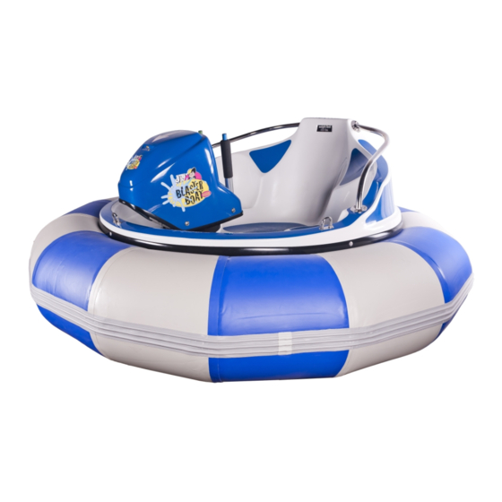
- Page 7 SPECIFICATIONS: ELECTRIC-POWERED BLASTER BOAT. DIMENSIONS: Overall diameter ............................72”(182 cm) Overall height ............................40”(101 cm) Wet weight ............................. 488lbs(222kg) Total battery weight ..........................248lbs(113kg) Super Tube II weight........................... 23lbs(11kg) Hull & deck weight ..........................139lbs(63kg) Minimum water depth ............................ 3ft(.91m) MOTOR: Model..............................24v 1750 rpm Type ..................Continuous duty 3/4 hp(1118w) 24v, permanent magnet Motor weight ..............................
- Page 8 SPECIFICATIONS: GAS-POWERED WATER BUG. DIMENSIONS: Overall diameter ............................72”(182 cm) Overall height ............................40”(101 cm) Wet weight ............................... 194lbs(88kg) Super Tube II weight........................... 23lbs(11kg) Hull & deck weight ..........................139lbs(63kg) Minimum water depth ............................ 3ft(.91m) ENGINE: Model..........................J&J equipped Honda BF2.3D Type ......................4-stroke, overhead valve, single cylinder Engine weight...............................32.0 lbs (14.6kg) Cooling system .............................
- Page 9 MONTHLY SERVICE SCHEDULE (Electric) Check Every Monthly or every Item # Item Service type Frequency 20 hrs 50 hrs 200 hrs Log hours of operation to determine proper maintenance intervals. Check Daily SB-120 Plug(s) Replace When damaged Grease terminals (2) ...
-
Page 10: Monthly Maintenance Chart
0-10 MONTHLY SERVICE SCHEDULE (Electric) Below are explanations of service listed in the monthly maintenance charts on previous page. Explanations of monthly maintenance shall include, but are not limited to the following: 1. SB-120 PLUG(S): Make sure that the plug is lubed with dielectric grease. Inspect the plug for deep grooving or signs of arcing. 2. - Page 11 0-11 MONTHLY SERVICE SCHEDULE (Gas) Monthly or Check Every Every Item # Item Service type every Frequency 20 hrs 50 hrs 150 hrs 200 hrs Log hours of operation to determine proper maintenance intervals. Check level Daily Engine(*) Change oil ...
- Page 12 0-12 MONTHLY SERVICE SCHEDULE (Gas) Below are explanations of service listed in the monthly maintenance charts on previous page. Explanations of monthly maintenance shall include, but are not limited to the following: 1. ENGINE: Always use API service SG.SF/CC.CD. designation shown on the container; see “Engine Oil” in the Honda Shop Manual.
-
Page 13: Pre-Opening Daily Checklist
0-13 Pre-Opening Daily Checklist (Electric) Week of Bumper boat ID# Attendant must initial each empty box every day. If any- thing is not OK, see a supervi- Body color sor. Item Service type Tues BOAT Tube - Check pressure Hull - Visually inspect Receiver - Visually inspect... - Page 14 0-14 Pre-Opening Checklist - Explanation (Electric) Below are explanations of service listed in the Pre-Opening Checklist chart on previous page. Explanations of Pre-Opening Checklist shall include, but are not limited to the following: BOATS: TUBE - Check air pressure using a high-quality, low-pressure gauge. Super Tube should be inflated to 2-3 PSI. HULL - Check for cracks and missing hardware.
- Page 15 0-15 Pre-Opening Daily Checklist (Gas) Bumper boat ID# Attendant must initial each empty box every day. If any- thing is not OK, see a supervi- Body color sor. Item Service type Tues BOAT Tube - Check pressure. Hull - Visually inspect. Receiver - Visually inspect.
- Page 16 0-16 Pre-Opening Checklist - Explanation (Gas) Below are explanations of service listed in the Pre-Opening Checklist chart on previous page. Explanations of Pre-Opening Checklist shall include, but are not limited to the following: BOATS: TUBE - Check air pressure using a high-quality, low-pressure gauge. Super Tube should be inflated to 2-3 PSI. HULL - Check for cracks and missing hardware.
-
Page 17: Bumper Boat Area Checklist
0-17 Bumper Boat Area Checklist Week of Attendant must initial each empty box every day. If any- thing is not OK, see a supervi- sor. Item Service type Tues POND Boat rope & hooks -Check for broken hooks and unsafe ropes. Dock Rail -Check for cracks or loose hardware. -
Page 18: Printable Work Order Tags
0-18 Printable Work Order Tags This sample maintenance work order tag can be copied for use in your facility. Copy and cut tag along dashed line and fold along the fold line indicated. Simply attach a maintenance work order tag to a machine in need of repair. When maintenance is complete, file with other service and maintenance information. -
Page 19: How A Warranty Is Processed
0-19 HOW A WARRANTY IS PROCESSED 1. The customer contacts J&J with the warranty problem. The product warranty department or parts department gathers information and makes arrangements to send the needed replacement to the customer. The parts department also gives the customer an RMA # (Return Merchandise Authorization) at that time. (Please note: RMA # must appear on returned goods package. -
Page 20: Product Return Procedures
0-20 PRODUCT RETURN PROCEDURES RETURNED GOODS POLICY: No merchandise may be returned, nor any account adjustments made, unless authorized by J&J Amusements, Inc. A Return Merchandise Authorization (RMA#) is required for all returns. Only items authorized (listed) on an RMA# may be returned. - Page 21 0-21 LIMITED WARRANTY - BUMPER BOAT This warranty is limited to J&J Amusements, Inc. products, parts and accessories when distributed by J&J Amusements, Inc., 4897 Indian School Road NE, Suite 150, Salem, Oregon 97305-1126 USA, hereinafter referred to as (J&J). Products Covered By This Warranty: Length Of Warranty: Bumper Boat hull (excluding Honda motors)
- Page 22 0-22 LIMITED WARRANTY - SUPER TUBE II This warranty is limited to J&J Amusements, Inc. products, parts and accessories when distributed by J&J Amusements, Inc., 4897 Indian School Road NE, Suite 150, Salem, Oregon 97305-1126 USA, hereinafter referred to as (J&J). Products Covered By This Warranty: Length Of Warranty: Super tube II...
-
Page 23: General Information
0-23 UNPACKING & SETUP General Information ..........1-19 Battery Fill Kit Installation (electric only)....1-24 Unpacking..............1-20 Battery Wiring (electric only) ........1-25 Tube Setup ..............1-21 Boat Launch Procedure ..........1-27 Boat Assembly ............1-22 Motor Installation............. Battery Installation (electric only).......1-23 1-28 Your new J&J bumper boat is shipped in a heavy-duty cardboard box. This section of the Service Manual describes the process to get your new bumper boat(s) unpacked and ready for service. -
Page 24: Unpacking
0-24 UNPACKING Cut and remove the metal packing straps. Remove the box top and place it aside for later use. Remove the box sides and discard. Remove the tube and place it aside with the box top. Remove plastic wrap from the boat hull and discard. Leave the boat hull on the cardboard base for protection from scratches. -
Page 25: Tube Setup
0-25 TUBE SETUP Carefully unfold the tube and lay it flat on the boat box top. Note: Boat hulls are normally packaged with their correctly color-coordinated tube. Fill the tube with a Super Tube fill adapter (#00367) as shown in figures 1 & 2, a Super Tube pressure test adapter/filler (#2-60-A0006) as shown in figures 3 &... -
Page 26: Boat Assembly
0-26 BOAT ASSEMBLY Lift the hull assembly and carefully place it inside the tube. ‹ CAUTION › The hull is heavy. Use two people when lifting the hull assembly. Make sure to grab the lip of the boat bottom when lifting the assembly. -
Page 27: Battery Installation (Electric Only)
0-27 BATTERY INSTALLATION (Electric only) Open the boat top and use the wooden prop rod to hold the top up. ‹ CAUTION › Place the wooden prop rod so it does not be- come dislodged while holding the boat top in “up” position. Remove items provided inside boat: •... -
Page 28: Battery Fill Kit Installation (Electric Only)
0-28 BATTERY FILL KIT INSTALLATION (Electric only) Remove the caps from the batteries and place aside for later use. ‹ WARNING › Wear protective (rubberized) gloves when handling batteries. Avoid contact with battery acid. Remove the manifold valves from the hose T-fittings. Loosely install the manifold valves into the batteries. -
Page 29: Battery Wiring (Electric Only)
0-29 BATTERY WIRING (Electric only) NOTICE See the battery wiring diagram on page 4-18. Battery 1 Locate battery #1. Install a cable from the positive post of battery #1 to the negative post of battery #2. Battery 2 Install a cable from the positive post of battery #2 to the negative post of battery #3. - Page 30 0-30 Install the “RED” cable from the breaker to the positive post of battery #4. Battery 4 Battery 1 Battery 2 Battery 3 Install the “BLACK” cable from the negative main power post to the negative post of battery #1. Battery 1 Battery 3 Battery 2...
-
Page 31: Boat Launch Procedure
0-31 BOAT LAUNCH PROCEDURE Install the boat & dock rail hooks as described in the dock rope installation on page 1-12. Carefully move the boat to the edge of the pond. NOTICE Make sure to move the boat with the box lid underneath it to prevent damage. -
Page 32: Motor Assembly
0-32 MOTOR INSTALLATION Have a helper carefully pass the motor assembly to the person in the boat. GAS ENGINE Check the engine and gear box oil level before installing. “Refer to the Honda owner’s manual “ Position the lower unit of the motor so the prop guard will clear the motor pivot. - Page 33 0-33 WARNING DECALS (TYPICAL LOCATIONS) Go-karts are terribly unforgiving of carelessness or neglet. To help avoid incidents and accidents, it is imperative that warning decals are legible and in place. The following outlines the typical locations of particular warning decals on bodied and non-bodied go-karts, as installed at the time of manufacture.
- Page 34 0-34 001688 001686 2-40-0001 001681 www.jjamusements.com 00156 009800 503-304-8899 Specifications subject to change without notice - Check our website for valuable information including videos, workshop and operations manuals. www.jjamusements.com...
-
Page 35: Breaker/Main Cutoff Switch
BOAT TOP ASSEMBLY General boat top information ........1-1 Trim ................1-18 Breaker/main cutoff switch (electric only) ....1-2 Vent plate (electric only)..........1-21 Volt meter (electric only) ..........1-5 Reinforced rubber hinge (electric only) ......1-23 Bilge pump fuse (electric only) ........1-7 Battery charging cable (electric only) ......1-27 Pivot receiver ..............1-8 Battery-fill quick-release coupler (electric only) ..1-30 Safety &... -
Page 36: General Information
BREAKER/MAIN CUTOFF SWITCH (Electric only) General Information ............1-2 Removal/Replacement ..........1-3 The safety switch/breaker is a marine-grade unit that combines switching and circuit protection into a single de- vice, which meets SAE J1171 requirements for marine application. All power out to the boat is routed through here, as well as all incoming power from the charging device and wire leads. - Page 37 BREAKER SWITCH (Electric only) NOTICE: All power goes through breaker. When breaker is in the off position, there will be no reading displayed on volt meter, (The volt meter will display 0 volts) and the batteries cannot be charged. REMOVAL/INSTALLATION. Disconnect the (-) negative cable from battery #1.
- Page 38 Hold the inside nylock nut during the next step. Remove the bolts. Carefully remove the breaker. NOTICE: Inspect wires and connections for corrosion/ damage. Clean off any corrosion from cable ends, and apply corrosion block on the cable ends before re-installing. Replace as needed.
-
Page 39: Volt Meter (Electric Only)
VOLT METER (Electric only) General Information ............1-5 Removal/Installation ............1-6 The built-in volt meter constantly monitors the overall condition of the battery pack. When in “charge mode” the typical volt meter reading will be approximately 27.6 VDC. The table below indicates load readings, showing the representative system condition of the batteries. - Page 40 VOLT METER (Electric only) The volt meter is located on the back of the boat top, to the left of the vent plate. REMOVAL/INSTALLATION. Remove the two nuts that hold the bracket to the boat top. Remove the volt meter from the outside of the boat top. (See the wiring diagram for volt meter connections on page 4-18).
-
Page 41: Bilge Pump Fuse (Electric Only)
BILGE PUMP FUSE (Electric only) REMOVAL/INSTALLATION The bilge pump fuse is located on the back of the boat top to the left of the vent plate. With a flat screwdriver, push and turn counterclockwise 1/4 turn. Remove the fuse and holder by pulling outward. Remove the fuse from the holder. -
Page 42: General Information
PIVOT RECEIVER General Information ............1-8 Pivot Receiver Removal/Installation ......1-9 503-304-8899 Specifications subject to change without notice - Check our website for valuable information including videos, workshop and operations manuals. www.jjamusements.com... - Page 43 PIVOT RECEIVER REMOVE/INSTALLATION The pivot is attached with 8 bolts and nylock nuts, and 16 flat washers. REMOVAL/INSTALLATION Remove the bolts, nylock nuts and washers. Install a new pivot by using the existing holes. Replace the hardware with new hardware as needed. ID PLATE: Remove the ID plate from the old pivot.
-
Page 44: Dock Rail Rope Installation
1-10 SAFETY RAILS & DOCK RAIL HOOKS General Information ..........1-10 Dock Rail Rope Installation ........1-12 Safety Rails & Dock Rail Hooks ........1-11 Dock rails are now fully stainless steel with blue powder coat. J&J Dockrails are made from stainless steel and powder coated for ultra protection. - Page 45 1-11 SAFETY RAILS & DOCK RAIL HOOKS The safety rails are mounted with 6 phillips head bolts, 6 nylock nuts and 6 flat washers. REMOVAL/INSTALLATION Hold each screw from the outside of the boat top. Remove the nylock nuts and flat washers. Replace the hardware as needed.
-
Page 46: Dock Rail Rope Installation
1-12 DOCK RAIL ROPE INSTALLATION The length of rope needed varies depending on dock rail placement and water level. TECH TIP: After cutting the rope, lightly singe and melt one end of the rope; form a point using a folded piece of cardboard (match- book cover, for example), and cover the end to form the point while insulating your fingers from the heat. - Page 47 1-13 To make the loop, insert the rope through the end of the fid and the thread the fid through the rope. Pull the rope, making a small loop at the hook. Insert the fid at the first rope thread under the loop. Thread the fid back through each side of the loop.
- Page 48 1-14 Pass the fid down through the hollow core of the rope just below the loop. Run the fid down the hollow center of the rope for approxi- mately six inches. Bring the fid out through the stitching. Tuck any excess back inside the hollow core of the rope. 503-304-8899 Specifications subject to change without notice - Check our website for valuable information including videos, workshop and operations manuals.
- Page 49 1-15 With the other end of the rope, repeat the previous steps, without the boat hook, to permanently attach the rope to the dock rails. Insert the rope through the eye of the dock rail. Insert the fid through the rope about 10 inches down. Insert the rope through the end of the fid and thread the fid through the rope.
- Page 50 1-16 Thread the fid back through each side of the loop. Pass the fid down the hollow core of the rope just below the loop. Run the fid through the penetrated rope and continue down the hollow center for approximately six inches. 503-304-8899 Specifications subject to change without notice - Check our website for valuable information including videos, workshop and operations manuals.
- Page 51 1-17 Bring the fid out through the stitching. Tuck the excess back inside the hollow core of the rope. The dock rail rope should have about 2 inches of slack when attached to the boat so the hooks can be easily connected. 503-304-8899 Specifications subject to change without notice - Check our website for valuable information including videos, workshop and operations manuals.
-
Page 52: Trim
1-18 TRIM General Information ..........1-18 Trim Installation/Removal ..........1-19 The boat trim serves to protect the tube and your hands from the exposed fiberglass edge on the bottom of the boat top. 503-304-8899 Specifications subject to change without notice - Check our website for valuable information including videos, workshop and operations manuals. www.jjamusements.com... - Page 53 1-19 TRIM INSTALLATION/REMOVAL The boat trim is mounted with 9 stainless steel rivets and double-sided tape. REMOVAL To remove the old trim, first drill out the rivets and pull the trim off of the fiberglass. Make sure to remove any trim adhesive and thor- oughly clean off the surface of the fiberglass before installing the new boat trim.
- Page 54 1-20 Drill through the outside of the trim by matching the existing rivet holes. Insert rivets through the trim. Install a backing washer on the inside of each of the rivets. Install the rivets to boat top. VISIT WWW.JJAMUSEMENTS.COM/TECHNICAL/INDEX.HTM FOR TECHNICAL INFORMATION RELATED TO OUR PRODUCTS.
-
Page 55: Vent Plate (Electric Only)
1-21 VENT PLATE (Electric only) General Information ..........1-21 Vent Plate Assembly ..........1-22 Vent Plate The vent plate is a multi-purpose access port into the boat hull. It acts as a vent for the hull and also allows easy access to the charge cable. - Page 56 1-22 VENT PLATE ASSEMBLY (Electric only) The vent plate is located at the rear of the boat top. Open the vent plate to access the charging cable, and to perform visual inspections. To open, turn counterclockwise. The v ent plate assembly is mounted with six 10-32 phillips-head screws with six 10-32 nylock nuts.
-
Page 57: Reinforced Rubber Hinge (Electric Only)
1-23 REINFORCED RUBBER HINGE (Electric only) General Information ..........1-23 Reinforced Rubber Hinge ..........1-24 The reinforced rubber hinge connects the boat top to the hull. - Page 58 1-24 REINFORCED RUBBER HINGE (Electric only) REMOVAL/INSTALLATION Disconnect wiring from the boat hull to the boat top (see wiring diagram on page 4-18). Close the boat top. From the rear, drill out the six rivets from the hull. Remove the top from the hull. Place the top upright on a soft surface.
- Page 59 1-25 Drill out the rivets and remove the rubber hinge. Insert five 3/16”x 3/4” aluminum rivets (J&J#002473) through the bracket and rubber hinge. Install the rivets through the backing plate of the rubber hinge and the boat top. J&J carries all locktite brand threadlocker and other sealants. 503-304-8899 Specifications subject to change without notice - Check our website for valuable information including videos, workshop and operations manuals.
- Page 60 1-26 Place the boat top on the hull. Open the vent plate to access the rubber hinge. Pre-drill through the rubber hinge. Insert six rivets through the hull and rubber hinge. Insert a backing washer on inside of each rivet. Holding the backing plate, insert the rivets.
-
Page 61: Battery Charging Cable (Electric Only)
1-27 BATTERY CHARGING CABLE (Electric only) General Information ..........1-27 Battery Charging Cable ..........1-28 The battery charging cable is approximately 15’ long and is located inside the boat. It is easily accessed through the vent plate access cover located on the back of the boat top. - Page 62 1-28 BATTERY CHARGING CABLE (Electric only) The battery charging cable is approximately 15’ long and is located inside the boat. The charging cable feeds out through the removable vent cover, guided by the eye bolt. A clamp-on cable stop pre- vents over-extension of the cable.
- Page 63 1-29 Pull the charging cable out through the inside of the boat top. Loosen the rubber cable stop. Remove the cable stop from the cable. Close the boat top. Pull the cable out through the vent plate hole. Pull THE RIGHT TOOL FOR THE JOB: HexCrimp jr terminal crimping tool. J&J #2-70-0073-120 503-304-8899 Specifications subject to change without notice - Check our website for valuable information including videos, workshop and operations manuals.
-
Page 64: Battery-Fill Quick-Release Coupler (Electric Only)
1-30 BATTERY-FILL QUICK-RELEASE COUPLER The battery filling system allows easy top-off of the battery water level from the outside of the boat. Simply attach the battery fill squeeze bulb (J&J#2-70-A0021C) to the access port on the back of the boat top to fill all the batteries to equal levels. -
Page 65: Motor Power Supply Cable
1-31 MOTOR POWER SUPPLY CABLE (Electric only) General Information ..........1-31 Motor Power Supply Cable ........1-32 J&J # 2-70-A0011... - Page 66 1-32 MOTOR POWER SUPPLY CABLE (Electric only) REMOVAL/INSTALLATION Disconnect wiring at the main post (see wiring diagram page 4-18). <<CAUTION>> Remove the ground wire from the battery to avoid electrical shock. Loosen the plastic cable clamp. Slide the cable through the loosened plastic “Adel”-style clamp.
- Page 67 1-33 Carefully loosen the nut from the plastic strain relief elbow. Remove the nut by sliding it to the cable end. Remove the cable through the boat top. (Note the location of the elbow for installation. See Figure 1.) Figure 1 VISIT WWW.JJAMUSEMENTS.COM/TECHNICAL/INDEX.HTM FOR TECHNICAL INFORMATION RELATED TO OUR PRODUCTS.
- Page 68 1-34 3/27/2012 A Division of J&J Amusements, Inc. Bumper Boat Motor Work Bench Mount 800-854-3140 / 503-304-8899 www.FunPartsXpress.com A Receiver mounted to your work bench will make servicing your fleet of bumper boat motors SAFER and QUICKER. There’s no better way to hold your motors steady while servicing.
-
Page 69: Lower Assembly
BOAT HULL - LOWER ASSEMBLY General boat hull assembly .........2-1 Bilge pump (electric only) .........2.6 Main power post (electric only) ........2-2 Battery-full kit (electric only) ........2-11 Boat half protector (electric only).........2-4 Super tube ..............2-13 This section of the Service Manual describes the various components of the boat hull assembly, how to diagnose prob- lems and the removal and replacement of parts associated with the boat hull. - Page 70 MAIN POWER POST (Electric only) General information ............2-2 Positive & negative main power post ......2-3 Power post, pre-2012 Power post, post-2012 Your J&J Blaster Boat may be equipped with one of two types of power posts. The pre-2012 version utilizes two rounded posts;...
- Page 71 MAIN POWER POST (Electric only) (FOR BOATS MANUFACTURED BETWEEN 2008- 2011) The positive and negative main posts are located at the rear of boat hull. <WARNING> Before removing wires, disconnect the main ground wire from the negative power post. REMOVAL: Disconnect the negative cable from the battery.
- Page 72 BOAT HALF PROTECTOR (Electric only) General information ............2-4 Boat half protector ............2-5 The boat half protector acts as a seal for the motor cavity in the hull, preventing any water from entering the hull.
- Page 73 BOAT HALF PROTECTOR (Electric only) Unscrew the clamps and remove the protector. Carefully remove and clean any silicone from the boat hull. Install the protector and tighten the clamps securely. Apply silicone between the boat hull and protector. (For best results, use J&J #013331.) Let the silicone cure before putting the boat back in service.
- Page 74 BILGE PUMP (Electric only) General information ............2-6 Bilge pump assembly removal ........2-8 Diagnosing problems...........2-7 The bilge pump and fuse circuit feeds directly from the power distribution post/buss. The main power feeds via the red wire to the accessible fuse holder outside (located on the back of the boat top), then through the green/brown wire to the pump.
- Page 75 DIAGNOSING PROBLEMS (Electric only) Most bilge pump problems are mechanical; ie: plugged screen, blocked impellor or foreign material causing impellor drag. PROBLEM: Pump does not work, and daily inspection shows standing water in the hull. Solution: Remove water from the hull. Use a pump and discharge hose from spare parts and clip the leads to the bat- tery pack.
- Page 76 BILGE PUMP ASSEMBLY REMOVAL (Electric only) Disconnect wiring from the main post (see the wiring diagram for bilge pump connections on page 4-18). Squeeze the (blue) mounting tabs located on each side of the pump. Remove the pump from its mount. The screen is located between the pump and the mount.
- Page 77 Remove the two 10-24 nylock nuts. NOTICE: Replacement of the pump mount and screen is needed only if damaged. Remove the bilge pump mount from the hull. To disconnect the output hose, remove/loosen the plastic hose clamp. Pull and slightly twist the hose to remove it from the pump. VISIT WWW.JJAMUSEMENTS.COM/TECHNICAL/INDEX.HTM FOR TECHNICAL INFORMATION RELATED TO OUR PRODUCTS.
- Page 78 2-10 Remove/loosen the plastic hose clamp. Pull and slightly twist the hose to remove it from the fitting. To remove the hose fitting, carefully hold the inside plastic nut. Remove the outside plastic nut. Remove the fitting from the inside of the hull. KEEPING YOUR BUMPER BOAT POOL CLEAN &...
- Page 79 2-11 BATTERY-FILL KIT (Electric only) General information ..........2-11 Battery-Full kit installation .........2-12 The battery filling system allows easy top-off of the battery water level from the outside of the boat. Simply attach the battery fill squeeze bulb (J&J#2-70-A0021C) to the access port on the back of the boat top to fill all the batteries to equal levels.
- Page 80 2-12 BATTERY-FILL KIT INSTALLATION (Electric only) Remove the caps from the batteries and place aside for later use. Remove the manifold valves from the hose T-fittings. Loosely install the manifold valves into the batteries. Make sure the manifold valves are flush with the battery be- fore tightening.
- Page 81 2-13 SUPER TUBE General information ..........2-13 Checking super tube for leaks ........2-16 Super tube inflation ...........2-14 Patching super tube ...........2-17 The Super Tube II is built with a urethane-coated fabric.
- Page 82 2-14 SUPER TUBE INFLATION FILL ADAPTER Insert a fill adaptor and turn clockwise 1/2 turn. Use a rubber-tip blow gun to fill the tube. VALVE FILL ADAPTER Insert a valve fill adaptor and turn clockwise 1/2 turn. Supertube fill adapter & pressure Test adapter &...
- Page 83 2-15 Use a tire inflator to fill the tube. VACUUM/BLOWER INFLATOR Open the tube valve and cover it with an inflator hose. Turn the blower on to fill. Inflate the tube to the recommended 3 PSI. Check it with a low-pressure gauge. Before returning the boat to service, check the valve for leaks by applying a solution of soapy water.
- Page 84 2-16 CHECKING SUPER TUBE FOR LEAKS Fully inflate the tube. Place three to four drops of washing detergent in a spray bottle with water. Check small areas of the tube at a time, spraying the surface of the tube and looking for any bubbles. Draw a small circle around any punctures or rips in the tube (for easy location of the repair), then deflate tube.
- Page 85 2-17 PATCHING SUPER TUBE Completely clean the surface of the tube to be patched before applying glue. Remove any 303 or other silicone/petroleum-based product from the tube surface. Follow the gluing instructions closely. Use or cut a vinyl patch from the repair kit making sure it is large enough to cover the damaged area with at least 1 to 2 inches of extra vinyl on all sides.
- Page 86 2-18 Place the patch over the damaged tube surface and use roller or old spoon to squeeze any air out of the patch, pressing the material together. Wait at least 24 to 48 hours before reinflating the tube. Pressure test the tube by inflating it and checking the patch with soapy water.
- Page 87 2-19 SUPER TUBE VALVE REPLACEMENT Insert a valve removal tool by lining up the prongs on the tool with the corresponding slots in the valve. With tube deflated, grasp the female fitting through tube. Once you have a solid grip, unscrew the valve by turning counterclockwise.
- Page 88 2-20 Fill the tube using the Super Tube fill adapter and an air-filler nozzle. Inflate the tube to the recommended PSI of 3 lbs. Before returning the boat to service, check the valve for leaks by applying a solution of soapy water. If bubbles form, the valve needs to be tightened.
- Page 89 Motor Assembly (Electric only) General information ............3-1 Solid state switch ............3-25 Motor cover..............3-2 Boat captain ..............3-27 Control rods/grips/handlebars ........3-4 Pivot ................3-29 Flex wire ..............3-8 Lower unit assembly ..........3-33 Motor ................3-11 Squirt pump assembly ..........3-37 Magnetic trigger ............3-19 SB-120 Terminal replacement ........3-42 Motor relay..............3-21 This section of the Service Manual describes the various components of the electric motor assembly, how to diagnose problems, and the removal and replacement of parts associated with the motor.
-
Page 90: General Information
MOTOR COVER General Information ............3-2 Motor Cover And Neoprene Protector ......3-3... -
Page 91: Handle Bar
MOTOR COVER AND NEOPRENE PROTECTOR Remove the four 1/4” screws and washers to remove the mo- tor cover. Lift the motor cover to gain access to the squirter hose. Disconnect the squirter hose by pushing the gray tab on the quick-release coupler. - Page 92 CONTROL RODS/GRIPS/HANDLEBARS General Information ............3-4 Hand Grips..............3-6 Control Rods ...............3-5 Handlebar Assembly ...........3-7 The control rods are color coded, anodized aluminum rods that activate the motor and squirt pump functions. The green rod controls the motor power and the blue rod controls the squirt pump.
-
Page 93: Control Rods/Grips/Handlebars
CONTROL RODS Each control rod has a spring located between the rod and the bottom of the tube. If the rod doesn’t return to the fully raised position, the spring will need to be replaced. Unbolt the magnetic trigger to remove the control rod. Use a magnet to remove the spring. - Page 94 HAND GRIPS REMOVAL Use a razor blade and cut down the grip. Peel the grip away from the handlebar. INSTALLATION Set a new grip over the handlebar. Press the grip to move it down the handlebar. Tech Tip: To get the grip completely onto the handlebar, it may be helpful to use a blow gun to create a cushion of air between the two as you push the grip down the handlebar.
- Page 95 HANDLEBAR ASSEMBLY The handlebar assembly has two parts and is mounted on the motor with four 3/8” hex-head-mount bolts. (Part # 2-10-0003 handlebar mount plate ) (Part # 2-10-0002 handlebar ) Remove the gear box (see page 3-33). Remove the hex-head motor-mount bolts. After the bolts are removed, slide the plate up the drive shaft housing.
-
Page 96: Flex Wire
FLEX WIRE General Information ............3-8 Flex Wire Removal/Installation ........3-9 J&J# 2-70-A0038 The flex wire consists of a 10/2 gauge wire that feeds power from the main distribution post through the hull to the SB- 120 connector located at the motor pivot. Simple voltage drop tests can verify the condition of this harness. NOTICE: SHOULD THERE BE ANY PROBLEMS WITH THIS HARNESS, IT IS RECOMMENDED THAT THE ENTIRE HARNESS BE REPLACED. - Page 97 FLEX WIRE Remove the SB-120 connector from the bracket. Remove the cable clamps from the pivot cover. Remove the pivot assembly. (see page 3-29). Looking for that elusive tool or shop accessory? call j&J, we’ve got them. 503-304-8899 Specifications subject to change without notice - Check our website for valuable information including videos, workshop and operations manuals. www.jjamusements.com...
- Page 98 3-10 Lift and rotate the UHMW disk up over the steering stop. This will help with further disassembly. Remove the flex cable from the UHMW disk. Remove the wire from the handlebar assembly. Inspect all fiber washers and bushings, as they act as an insu- lator for the flex wires.
-
Page 99: Motor
3-11 MOTOR General Information ..........3-11 Motor Disassembly ............3-12 The high-efficiency, brush-type, permanent magnet motor seldom has problems. MOST COMMON PROBLEMS: Symptom: The motor will not turn when the actuating rod is in the “ON” position. Most common cause: The motor circuit is open. Measure the voltage going into the motor from the main motor posi- tive post (white wire), and measure the voltage going out of the motor (black wire). -
Page 100: Motor
3-12 MOTOR DISASSEMBLY Remove the motor cover and neoprene protector (see page 3-3). Remove the magnetic triggers (see page 3-25). Disconnect wiring connections at the power post (see wiring diagram on page 4-18). Remove the relay (see page 3-21). Add another fun feature to your bumper boat pond and generate more revenue! Pondside squirter #2-60-a0008 503-304-8899 Specifications subject to change without notice - Check our website for valuable information including videos, workshop and operations manuals. - Page 101 3-13 Remove the squirter assembly (see page 3-37). Remove the solid state switches (see page 3-25). Remove the flex wire assembly (see page 3-8). Specialty tools available at j&j. Call us to find that elusive tool. 503-304-8899 Specifications subject to change without notice - Check our website for valuable information including videos, workshop and operations manuals. www.jjamusements.com...
- Page 102 3-14 Remove the gearbox assembly and drive shaft (see page 3-34). Remove the pivot assembly (see page 3-29). Remove the UHMW lower disk. VISIT WWW.JJAMUSEMENTS.COM/TECHNICAL/INDEX.HTM FOR TECHNICAL INFORMATION RELATED TO OUR PRODUCTS. 503-304-8899 Specifications subject to change without notice - Check our website for valuable information including videos, workshop and operations manuals. www.jjamusements.com...
- Page 103 3-15 Remove the power post (see motor wiring schematic on page 4-19). Remove the four 3/8” hex-head motor mount bolts. Remove the handle bar assembly (see page 3-7). Remove the drive shaft housing. Dielectric grease and other grease Products available at j&j! 503-304-8899 Specifications subject to change without notice - Check our website for valuable information including videos, workshop and operations manuals.
- Page 104 3-16 Before motor disassembly, make sure to mark the location of the cap in relation to the motor casing. NOTICE If the motor cap is assembled 180 degrees off, this will reverse polarity and cause the motor to turn counter- clockwise.
- Page 105 3-17 Remove the brush caps. Remove the brushes. Remove the four cap bolts. BASIC RIDE TIMER; SIMPLE AND EFFECTIVE WITH LIGHT AND BUZZER TO ALERT ATTENDANT. #01328 503-304-8899 Specifications subject to change without notice - Check our website for valuable information including videos, workshop and operations manuals. www.jjamusements.com...
- Page 106 3-18 To remove the motor cap, tap off by using a rubber mallet or soft-blow hammer. Remove the cap. NOTICE Clean the commutator with an emory cloth and electric mo- tor cleaner, if needed. Clean off only the carbon build-up. Try not to remove any brass material.
- Page 107 3-19 MAGNETIC TRIGGER (J&J# 2-30-0005) General Information ..........3-19 Magnetic Trigger ............3-20 The magnetic trigger is a high-quality, neodymium magnet housed in an injection-molded holder that is designed to be “loose” when properly mounted, but not able to rotate because of the ears on the injection-molded part. The “down” side must face toward the solid state switch.
-
Page 108: Magnetic Trigger
3-20 MAGNETIC TRIGGER Remove the motor cover and neoprene protector (see page 3-3). Remove the magnetic trigger by removing the 1/4” shoulder bolt with an allen wrench. Inspect the nylon bushing and shoulder bolt. Replace as needed. Align the rode with the slot in the handlebars. Make sure the magnet in the trigger is pointed down, facing the solid state switch. -
Page 109: Motor Relay
3-21 MOTOR RELAY (J&J# 2-70-0033) General Relay Information.........3-21 Relay - Removal & Replacement .......3-23 Testing the Relay ............3-22 The relay (J&J# 2-70-0033) is a simple 24VDC marine-style unit. It consists of a spring-loaded plunger that is moved via an electromagnet. This magnet is created when the control circuit (two small contact posts) is energized via the micro/ solid state switch circuit. - Page 110 3-22 TESTING THE RELAY Symptom: The relay clicks, but the motor does not run or turns slowly. Most common causes: A faulty relay, battery or damaged wire. Measure the voltage at the negative input post (black 10-gauge wire). The voltage should match the battery voltage (same as the Negative input voltmeter reading on the back of the boat).
- Page 111 3-23 RELAY - REMOVAL & REPLACEMENT Remove the motor cover and neoprene protector (see page 3-3). Remove the black and white wire lead from the power post. Disconnect the yellow wire lead from the relay. Cut the black wire lead above the yellow, 10-gauge butt connector.
- Page 112 3-24 Remove the 5/16” bolt that secures the relay to the motor housing and remove the relay. Install the new relay. <CAUTION> Use only a 5/16” x 1/2” bolt with; lock and a flat washer. This is necessary in order to keep the bolt from causing internal damage to the motor.
-
Page 113: Solid State Switch
3-25 SOLID STATE SWITCH General Information ..........3-25 Solid State Switch ............3-26 The solid state switches are completely sealed and utilize magnetic triggers to turn on a low-amperage circuit and energize the pull-in windings of the motor relay, or activate the squirt pump. These have a built-in LED light that serves as a self-diagnostic tool to aid in troubleshooting these devices. - Page 114 3-26 SOLID STATE SWITCH Remove the magnetic trigger (see page 3-19). Remove the wire leads from the power post (see wiring diagram on page 4-19). On the under-side of the motor, remove the solid state switch mounting nuts. Remove the solid state switch. Note: There is NO left or right solid state switch;...
-
Page 115: Boat Captain
3-27 BOAT CAPTAIN (Standard equipment on U.S. models only) General Information ..........3-27 Testing the Boat Captain ..........3-28 This device individually controls the motor via the motor solid state switch and/or the squirt pump via its solid state switch. Like the switch, it controls the ground side of the circuit. Attach the j&j pivot receiver to a sturdy workbench To secure a boat motor to a work bench. - Page 116 3-28 TESTING THE BOAT CAPTAIN To bypass the remote control for the squirt pump, disconnect the orange lead from the remote to the black lead of the switch. Jumper the switch’s black lead to the ground post. The squirt pump and the switch should now work normally. To bypass the remote control for the motor, disconnect the white lead from the remote to the black lead of the motor solid state switch.
-
Page 117: Pivot
3-29 PIVOT General Information ..........3-29 Pivot ................3-30 503-304-8899 Specifications subject to change without notice - Check our website for valuable information including videos, workshop and operations manuals. www.jjamusements.com... - Page 118 3-30 PIVOT Place the motor upside down with the motor cover removed. Remove the six allen-cap screws. Next, remove the four 5/16” nuts. Note the placement and use of the flat washers and spacer sleeves. Make sure that all threads are treated with anti- galling and corrosion resistant thread compound, such as Loctite®...
- Page 119 3-31 Remove the pivot bushing. Inspect the pivot bushing and drive shaft bushing for wear (i.e. grooves, pitting and cracking). If any of these conditions exist, it is recommended that the part be replaced. The mount bushings do have a top and bottom. Position the bushings’...
- Page 120 3-32 Install the drive shaft housing bushings. Install the pivot and bushings. Install the pivot shield. Install and tighten the pivot bracket nuts to 20 ft. lbs. <WARNING> If the pivot bracket nuts are over-tightened, binding of the pivot assembly may occur. Finish by installing the allen-cap-headed screws.
-
Page 121: Lower Unit Assembly
3-33 LOWER UNIT ASSEMBLY General Information ..........3-33 Prop & Guard ............3-35 Gearbox/Drive Shaft ..........3-34 Anode ...............3-36 503-304-8899 Specifications subject to change without notice - Check our website for valuable information including videos, workshop and operations manuals. www.jjamusements.com... - Page 122 3-34 GEARBOX AND DRIVE SHAFT Remove the gearbox assembly. Next, remove the gasket and discard, as this item will be re- placed with a new gasket. (J&J #01981). Grasp the end of the shaft and remove. NOTICE: The keyway is welded in place on both ends of the drive shaft.
- Page 123 3-35 PROP AND GUARD Remove the prop guard cover. With a punch, carefully remove the roll pin from the prop. Pull the prop off of the shaft. Remove the prop guard backing plate. Reinstall the prop guard backing plate. Slide the prop onto the shaft, taking care to line up the prop holes with the corresponding holes on the shaft.
- Page 124 3-36 ANODE A galvanic anode is the main component of a galvanic cathodic protection (CP) system used to protect buried or sub- merged metal structures from corrosion. Anodes are made from a metal alloy with a more “active” volt- age (more negative electrochemical potential) than the metal of the structure.
- Page 125 3-37 SQUIRT PUMP ASSEMBLY (J&J# 2-60-A0014) General Information ..........3-37 Squirt Nozzle ............3-41 Squirt Pump Assembly ..........3-38 The squirt pump is a sealed, 24VDC, brushless, submersible-style pump that is powered through the same type of solid state switch and magnetic trigger system that operates the motor relay. The squirt pump is a sealed unit, and repairable problems center around debris in the impeller.
-
Page 126: Squirt Pump Assembly
3-38 SQUIRT PUMP ASSEMBLY Remove the motor cover and neoprene protector (see page 3-3). Cut and remove the zip tie from the hose. Remove the hose from the filter by squeezing the spring clamp and sliding the clamp away from the filter. Slightly pull and twist to remove the hose from the filter. - Page 127 3-39 Disconnect the wire from the squirt switch (see wiring diagram on page 4-19). The squirt pump fuse is located on the side opposite the handle bars. (Refer to page 4-6 for fuse testing procedures.) Disconnect the wire from the fuse holder. NOTICE Carefully pry the connector from the fuse holder by using a flat-blade screwdriver.
- Page 128 3-40 Cut the zip tie to remove the hose from the handle bar base. Carefully remove the wiring and hose from the handlebar plate. Remove the two bolts from the drive shaft housing. Note A metal anode is mounted between the squirt pump and drive- shaft housing.
- Page 129 3-41 SQUIRT NOZZLE The squirt nozzle is attached to the motor cover. Use an adjustable wrench and squeeze the spring clamp. Slide the clamp down the hose. Pull and slightly twist the hose to remove. Use a flat-blade screwdriver and turn clockwise to remove the nozzle from the motor cover.
- Page 130 3-42 SB-120 TERMINAL General Information ..........3-42 SB-120 Terminal Replacement ........3-43 NOTICE It is very important that the SB-120 plug connections be solid and secure. This section of the manual describes the correct installation procedures, however, if you have any doubt about the connection and your abilities to perform the task correctly, J&J does sell complete cable assemblies with all connectors in place.
-
Page 131: Sb-120 Terminal Replacement
3-43 SB-120 TERMINAL REPLACEMENT Part # 2-70-A0022 includes: Strain relief (2) Terminal contacts (2) 6-32 nylock nut (1) 6-32 machine screw (1) 10-32 nylock nut (2) 10-32 x 3/4 pan head screw (2) SB-120 housing (1) NOTE: SB-120 ASSEMBLY DOES NOT CONTAIN CLEAR POLY VINYL TUBING # 2-60-0094 <<WARNING>>... - Page 132 3-44 SB-120 TERMINAL REPLACEMENT Install a clear tube (J&J #2-60-0094) over the cable and install strain relief on both sides of the cable utilizing the two pan head-screws and nylocks. Insert the terminal contacts into the SB-120 housing and push until the terminal snaps into the housing. NOTICE: THE WHITE WIRE IS TO POSITIVE, THE BLACK WIRE IS NEGATIVE.
- Page 133 BASIC Electrical Troubleshooting General Information ............4-1 Equalizing Batteries ..........4-15 Basic Electrical Troubleshooting .........4-2 Battery Maintenance-Winter Storage ......4-16 Voltage Drop Test............4-4 Master Charger............4-17 Testing Fuse .............. 4-6 Wiring Schematic ............. 4-18 Major Electrical Components ........4-7 Motor Wiring Schematic .......... 4-19 Specific Gravity Test ..........
-
Page 134: Basic Electrical Troubleshooting
BASIC Electrical Troubleshooting Whenever testing for power (voltage) flow in the circuit, the FIRST order of business is to establish and verify the test unit is functioning properly and has a solid ground. When possible, attach the ground lead of the tester directly to the ground post of the battery pack. - Page 135 2) EVERYTHING HAS RESISTANCE. The wires, connectors, and switch contacts that make up a circuit all have some resistance and, as its name implies, resistance opposes (resists) current. In an undamaged, properly designed circuit, normal resistance is small enough that it doesn’t keep the load from working. UNWANTED RESISTANCE IN THE CIRCUIT REDUCES THE AMOUNT OF ELECTRICAL ENERGY DELIVERED TO THE LOAD.
-
Page 136: Voltage Drop Test
Voltage Drop Testing The battery pack contains four 6-volt, deep-cycle lead-acid flooded-type batteries connected in series to produce a 24vdc “pack.” 4-gauge copper cables are used to connect the pack and furnish power through the main breaker switch to the main distribution buss. Use the voltage drop test to check the battery-terminal- to-cable-end and battery-pack-to-breaker-switch for excessive resistance. - Page 137 Open-circuit problems such as broken, disconnected wires and/or connections stop current flow. After you fix an open circuit, switch the circuit on again and check for lingering voltage drop. Until you get current flowing and check the circuit again, you can’t know if the entire circuit is healthy. Although resistance-free connections, wires and cables would be ideal, most of them will contain at least some voltage drop.
-
Page 138: Testing Fuse
TESTING FUSE TESTING PROCEDURE FOR FUSE It is extremely important to understand that if a fuse looks good, it might not in fact be good! Fuses can appear to be fine and have a break in them so small that it cannot be seen by the naked eye. Therefore, it is important to check a fuse with an ohmmeter or a continuity tester instead of assuming that it is good. -
Page 139: Major Electrical Components
MAJOR ELECTRICAL COMPONENTS J&J battery-powered bumper boats utilize a simple 24VDC circuit containing the power pack, consisting of four 6VDC deep-cycle, 225 amp hour batteries wired in a series. 50 amp breaker/switch #2-60-0102 Power post, negative junction Battery Battery Battery Battery The cables and wire harnesses connect the components in the circuit. - Page 140 Testing: Use the DVOM and perform voltage drop tests to troubleshoot the wire harness and connectors. The unique portion of the wire harness system, the flex wires, allow the motor to rotate 320 degrees while maintaining current flow to the motor system. The system is designed to eliminate as many connectors as possible and avoid problem areas, while providing a simple, trouble-free unit.
- Page 141 The motor portion of the wire harness connects the solid state, magnetically-triggered on/off switches to the power relay, motor and squirt pump with a corresponding ground wire circuit to complete the loop. Kartrol Micro #1-60-8000 White lead from Kartrol unit Fuse Black lead to negative post #2-70-0104...
- Page 142 4-10 The magnetic trigger is a high-quality, neodymium magnet housed in an injection-molded holder that is designed to be loose when properly mounted, but not able to rotate. This is required, as there is top side and a bottom side to the unit. The bottom side must face toward the solid state switch.
- Page 143 4-11 J&J’s exclusive high-efficiency, brush-type, permanent magnet motor is directly activated through the relay; because this outboard-style unit operates in water, no “ramp up” is required. How a simple DC electric motor operates: When the coil is powered, a magnetic field is generated around the armature. The left side of the armature is pushed away from the left magnet and drawn toward the right, causing rotation.
- Page 144 4-12 A SIMPLE, EFFECTIVE AND PROVEN SYSTEM The J&J electric bumper boat utilizes four Trojan T-105, 6V Batteries rated at 225AH, and connected in series. This battery pack was chosen to provide the best performance-to-weight ratio and has proven, since its introduction in 1996, to have an excellent record of performance and durability.
-
Page 145: Specific Gravity Test
4-13 SPECIFIC GRAVITY TEST <CAUTION> MAKE SURE YOU WEAR GLOVES AND EYE PROTECTION WHILE PERFORMING THESE TESTS. 1. Do not add water at this time. 2. Fill and drain the hydrometer with electrolyte from battery cell 2 to 4 times before pulling out a sample. (See the Hydrometer battery tester on page 5-148) 3. - Page 146 4-14 <WARNING> A brand-new battery may have a low electrolyte level. Charge the battery first, and then add water if needed. Adding water to a battery before charging may result in overflow of the electrolyte. J&J recommends topping off the batteries once a week; with the J&J fill kit working properly, you cannot overfill the cells. WHAT IS THE PROPER ELECTROLYTE LEVEL? (IF YOU ARE USING J&J FILL KIT, THE FLOAT VALVES WILL SHUT OFF AUTOMATICALLY AT THE PROPER LEVEL) Liquid levels should be 1/8 inch below the bottom of the vent well (the plastic tube that extends into the battery).
-
Page 147: Equalizing Batteries
4-15 Equalizing Batteries Lead plates become sulfated as a natural result of their function; breaking this deposit loose and keeping the plates “clean” will equalize each cell’s ability to do its work. Equalizing is an overcharge performed on flooded/wet batteries after they have been fully charged. This action “scrubs” the plates, and the sulfates will fall to the bottom cavity of the battery. -
Page 148: Battery Maintenance-Winter Storage
4-16 Battery Maintenance - Winter Storage 1. On the days before leaving, do a thorough cleanup of connections and batteries. A mechanical inspection will help you to identify what terminals need replacement, and maximize the recharge rate. 2. Fully charge your battery systems. If possible, use your chargers in a low-amperage mode. It will take longer to fully charge the batteries, but will do a much better job. -
Page 149: Master Charger
4-17 MASTER CHARGER 24-VOLT/30-AMP OUTPUT BATTERY CHARGER WITH SWITCHABLE 120/240 VAC INPUT SELECTOR. 1. This micro-processor-controlled charger utilizes full-wave rectification. 2. Safety functions include: a. It will not turn on unless voltage is present at the charge lead (minimum 2 volts). b. - Page 150 4-18 Electric Bumper Boat - 24 Volt Wiring Schematic - 2012 VOLT Fuse VOLTS METER #2-70-0103 (Fuse holder) #2-70-0149 #2-70-0104 (Fuse) Black to negative (-) White to positive (+) 50 amp breaker/switch #2-60-0102 10/2 Cable to motor 10/2 Cable to charger #2-70-A0017 White White...
-
Page 151: Motor Wiring Schematic
4-19 MOTOR WIRING SCHEMATIC White lead from Kartrol unit Black lead to negative post Yellow lead to negative post Red lead to positive post Black lead White lead to positive post Yellow lead Wire (black) #2-70-A0031 Orange lead from Kartrol Micro to black lead on squirt pump switch Yellow lead from fuse to yellow lead on squirt pump switch Blue lead from squirt pump to positive post 503-304-8899... -
Page 152: Boat Captain Wiring Schematic
4-20 BOAT CAPTAIN WIRING SCHEMATIC 503-304-8899 Specifications subject to change without notice - Check our website for valuable information including videos, workshop and operations manuals. www.jjamusements.com... - Page 153 ENGINE ASSEMBLY General Information ............5-1 Pivot................5-3 Handle bar ..............5-2 Prop guard..............5-4 The Honda BF2.3D engine was chosen for its reputation for dependable service and its reduced emissions (less smoke and less oil in the water), this motor quietly performs. Initially designed for use in the corrosive marine environment, this dependable unit has been modified to be controlled from behind and transformed to operate in the bumper boat.
-
Page 154: Handle Bar
HANDLE BAR The Honda steering handle, throttle assembly and hardware is removed from the engine. The three stock extension case bolts (30mm) are removed and replaced with longer bolts (35mm) to mount the J&J handle bar. Also the handle bar is bolted to the stock steering handle mount with a shorter bolt (20mm) and a rubber cover ziped tied to the handle bar. - Page 155 PIVOT The removal, installion and maintenance for the pivot is performed with the same steps as for the electric motor (see page 3-29). 503-304-8899 Specifications subject to change without notice - Check our website for valuable information including videos, workshop and operations manuals. www.jjamusements.com...
- Page 156 PROP GUARD The prop guard used on the gas engine is also used for the electric motor (see page 3-25 for removal and installation). “Refer to the Honda shop manual for repairing, troubleshooting and maintaining the extension case.” 503-304-8899 Specifications subject to change without notice - Check our website for valuable information including videos, workshop and operations manuals. www.jjamusements.com...
-
Page 157: Motor Cover Decals
DECALS General Information ............6-1 Boat Top Decals ............6-161 Motor Cover Decals ............6-2 Decal Removal and Installation.......6-163 This section of the Service Manual depicts the location of various decals on the bumper boat and how to remove and replace them. - Page 158 MOTOR COVER DECALS (elecric only) “Arrow” and “Blaster Boat” motor decal are located on the top of the motor cover. (“Arrow decal” J&J #2-40-0001) (“Blaster Boat decal” J&J #001687) NOTE: The arrow decal indicates forward direction the boat will travel when motor is activated. “Blaster Boat”...
- Page 159 BOAT TOP DECALS J&J Amusements website decal is located at the right rear of the boat top under the vent plate. (J&J #009800) “Blaster Boat” decal is located on the boat top above the vent plate on the electric bumper boat. (J&J #001688) “Water Bug”...
- Page 160 BOAT TOP DECALS “Weight Limit 450 lbs” decal is located on the rear inboard side of the boat top. (J&J #2-40-0006) <SAFETY ITEM> This decal must be readable at all times to operate the boat. Replace as needed. “Warning-Never Stand Up While Boat Is Operat- ing”...
- Page 161 DECAL REMOVAL AND INSTALLATION REMOVAL Use a hot air gun to heat the decal. The heat is not for melting away the decal, but to heat the adhesive enough to removal the decal. Repeat until the decal is completely removed. Apply a small amount of WD-40 to a clean cloth (the cloth should be damp, but not soaked).
- Page 162 Decades of evolution have created the highest quality, best performing go-karts & bumperboats in the industry. Are you looking for a way to make more money? Here’s an easy way. Just mount a few of the Master Blaster Water Squirters around your bumperboat pond and voila! A simple, rugged money maker.
- Page 163 CARE & STORAGE General Information ............. 7-1 303 Aerospace Protectant ..........7-4 Fiberglass care & Maintenance ........7-2 Storage ................7-6 PROPER CARE IN THE “OFF SEASON”: Some bumper boat ponds do not operate all year long. For this reason, J&J Inc. has prepared this information on how to properly condition your bumper boat fleet for periods of storage or inactivity.
- Page 164 FIBERGLASS CARE AND MAINTENANCE WHAT IS FIBERGLASS? Fiberglass is a common term for fiber-reinforced plastic, or FRP, which is a plastic material strengthened using a fiber cloth. Most boats these days are made from fiberglass, along with pickup truck caps, motorhomes and even bathtubs! To give the fiberglass a smooth, shiny surface, a material called gelcoat is applied to the outer surface.
- Page 165 CLEANING FADED OR OXIDIZED FIBERGLASS There really isn’t any secret to cleaning faded or dull fiberglass; you just need some elbow grease and something to remove the oxidation. The application varies for different products, but in general, you need to rub the surface with the oxidation remover or polishing compound to remove the oxidized layer.
- Page 166 303 AEROSPACE PROTECTANT BUMPER BOATS - MAKE THEM LOOK BETTER AND LAST LONGER WITH 303 An enlarged side view of common vinyl fabric would show raw PVC (polyvinyl chloride) covered by a thin layer of plastic called the “topcoat”. The topcoat is the part of the vinyl you can see and touch. To keep vinyl fabric soft and flexible, manufacturers add agents known as plasticizers to the raw PVC.
- Page 167 303 FOR FIBERGLASS: Never buff or wax again! Like vinyl, gelcoat fiberglass (polyester resin) is a UV-sensitive plastic. Though manufacturers add UV stabilizers to vinyl and gelcoat fiberglass in the manufacturing process, these protective agents weaken over time and must be replenished if continuing UV protection is desired. Colored gelcoat fiberglass is particularly sensitive to UV degradation, and 303 Protectant is by far the easiest way to make colored fiberglass look like new again, and to keep it that way.
- Page 168 STORAGE BATTERIES When your boats are not in use and your park is closing for the season, it is a good idea to winterize your bumper boat batteries. To do this, there are a few steps to follow in order to maximize your batteries’ life. The first is to fill each battery up with water and fully charge each battery;...
Need help?
Do you have a question about the Bumper Boat 2014 and is the answer not in the manual?
Questions and answers