Table of Contents

Related Manuals for KERN KERN AES


Summary of Contents for KERN KERN AES
- Page 1 KERN & Sohn GmbH Ziegelei 1 Tel: +49-[0]7433- 9933-0 D-72336 Balingen Fax: +49-[0]7433-9933-149 E-Mail: info@kern-sohn.com Internet: www.kern-sohn.com Operation manual Analytical balances KERN AES/AEJ Version 1.2 09/2009 AES/AEJ-BA-e-0912...
-
Page 2: Table Of Contents
KERN AES/AEJ Version 1.2 09/2009 Operating Instructions Analytical Balances Table of Contents Technical Data..................5 Dimensions ........................7 Conversion tables for weighing units ................7 Declaration of conformity................ 8 Appliance overview.................. 9 Keyboard overview......................10 Overview of display......................11 Basic Information (General) ..............12 Proper use ........................ - Page 3 Menu......................27 10.1 Menu 1 ..........................28 10.1.1 Navigation in menu 1 ......................28 10.1.2 Overview Menu 1 .......................29 10.1.3 Settings for density determination..................32 10.1.4 Settings for tolerance weighing / add-up ................32 10.1.5 Settings for serial interface ....................33 10.2 Menu 2 ..........................34 10.2.1 Navigation in menu 2 ......................34 10.2.2...
- Page 4 Data output ..................... 73 14.1 RS 232C interface ......................73 14.2 Printer interface (unidirectional data exchange)............76 14.3 Description of interface ....................76 14.4 Data output........................77 14.4.1 Format for data transmission..................... 77 14.4.2 Signs..........................77 14.4.3 Numeric data ........................77 14.4.4 Units...........................
-
Page 5: Technical Data
1 Technical Data KERN AEJ 120-4M AEJ 220-4M Weighing range (max) 120 g 220 g Readability (d) 0.1 mg Minimum load (Min) 10 mg Verification value (e) 1 mg Verification class Adjustment weight intern Weighing Units mg, g, ct Reproducibility 0.1 mg Linearity ±... - Page 6 KERN AES 120-4 AES 220-4 Weighing range (max) 120 g 220 g Readability (d) 0.1 mg Recommended adjustment weight, 100 g (E1) 200 g (E1) not added (class) ct, dwt, g, gn, lb, mg, mo, oz, ozt, tl (Cn), Weighing Units tl (HK), tl (Singap.
-
Page 7: Dimensions
1.1 Dimensions 1.2 Conversion tables for weighing units Weighing unit Gram Carat Ounce Pound Troy ounce Penny weight 0.03527 0.00220 0.03215 0.64301 0.00705 0.00044 0.00643 0.12860 28.34952 141.74762 0.06250 0.91146 18.22917 453.59237 2267.96185 14.58333 291.66667 1ozt 31.10348 155.51738 1.09714 0.06857 1dwt 1.55517 7.77587... -
Page 8: Declaration Of Conformity
Niniejszym oświadczamy, że produkt, którego niniejsze oświadczenie zgodności dotyczy, jest zgodny z poniższymi normami. Заявление о Мы заявляем, что продукт, к которому относится данная декларация, соответствии соответствует перечисленным ниже нормам. Electronic Balance: KERN AES, AEJ Mark applied EU Directive Standards 2004/108/EC EN 55022 (2006) 2006/95/EC EN 60950 (2001) Date: 07.10.2008... -
Page 9: Appliance Overview
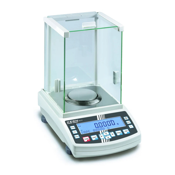
3 Appliance overview Wind screen Weighing plate Protection ring Air bubble Display RS 232 interface Printer interface Connection mains adapter Foot screw Underfloor weighing device Foot AES/AEJ-BA-e-0912... -
Page 10: Keyboard Overview
Keyboard overview Designation Function short key pressing • Taring • Zeroing TARE key • During numeric input increase of digit • Change menu settings ON/OFF • Turn on/off switch • Adjustment CAL-key • Calculate weighing data via interface PRINT-key • Cancel process/input •... -
Page 11: Overview Of Display
3.2 Overview of display Display Description Tolerance marker Power display (power supply for balance via line adapter) Balance in adding mode Stability display Prompt for reference optimisation Minus Display storage value, flashes during storage process →0← Zeroing display Bar graph/capacity display Adjustment symbol This is displayed during setting of date/time. -
Page 12: Basic Information (General)
4 Basic Information (General) 4.1 Proper use The balance you purchased is intended to determine the weighing value of material to be weighed. It is intended to be used as a “non-automatic“ balance, i.e. the mate- rial to be weighed is manually and carefully placed in the centre of the weighing plate. -
Page 13: Basic Safety Precautions
5 Basic Safety Precautions 5.1 Pay attention to the instructions in the Operation Manual Carefully read this operation manual before setup and commissioning, even if you are already familiar with KERN balances. 5.2 Personnel training The appliance may only be operated and maintained by trained personnel. 6 Transportation &... -
Page 14: Unpacking And Erection
Major display deviations (incorrect weighing results) may be experienced should electromagnetic fields (e.g. due to mobile phones or radio equipment), static elec- tricity accumulations or instable power supply occur. Change location or remove source of interference. 7.2 Unpacking and erection Carefully remove the balance from the packaging, remove plastic cover and setup balance at the intended workstation. -
Page 15: Connection Of Peripheral Devices
Levelling balance Air bubble Foot screw Level balance with foot screws until the air bubble of the water balance is in the prescribed circle. Mains connection Power is supplied via the external mains adapter. The stated voltage value must be the same as the local voltage. -
Page 16: Initial Commissioning
7.4 Initial Commissioning In order to obtain exact results with the electronic balances, your balance must have reached the operating temperature (see warming up time chap. 1). During this warming up time the balance must be connected to the power supply (mains, accumulator or battery). -
Page 17: Simple Weighing
8.2 Simple weighing Place goods to be weighed on balance. Wait until the stability display appears [ ]. Read weighing result. stable If the display shows the stability display [ ] the bal- ance is in a stable status. If the status is instable the [ ] display disappears. -
Page 18: Net/Gross
8.4 Net/gross The dead weight of any weighing container may be tared away by pressing a but- ton. For subsequent weighings the net weight of the goods to be weighed as well as the gross weight goods + taring container can be displayed. Condition: Menu setting [q SET.1],see chpt. -
Page 19: Display Speed
8.5 Display speed To change the display speed of the weighing balance without invoking the menu, press the S-key. However, this only will limit your options to the three settings nor- slow fast. Within the menu it is possible to fine-tune the weighing balance for certain ambient conditions and measuring purposes, see chpt. -
Page 20: Underfloor Weighing
8.7 Underfloor weighing Objects unsuitable for placing on the weighing scale due to size or shape may be weighed with the help of the flush-mounted platform. Proceed as follows: • Switch off the balance • Remove the weighing pan and carefully turn over the weighing balance. •... -
Page 21: Adjustment
9 Adjustment As the acceleration value due to gravity is not the same at every location on earth, each balance must be coordinated - in compliance with the underlying physical weighing principle - to the existing acceleration due to gravity at its place of location (only if the balance has not already been adjusted to the location in the factory). -
Page 22: Adjustment With External Weight (Only Aej)
9.2 Adjustment with external weight (only AEJ) During adjustment tests the balance automatically compares the saved value of the adjustment weight with the actual value. This is only a check, i.e. no values are changed. Condition: Menu setting [ ], see chpt. 10.1.2 x CA. -
Page 23: Adjustment With External Weight (Only Aes)
9.3 Adjustment with external weight (only AES) Carry out adjustment with the help of the recommended adjustment weight (see chapter 1 “Technical Specifications”). Info about adjustment weights can be found on the Internet at: http://www.kern- sohn.com Condition: Menu setting [ ], see chpt. -
Page 24: Adjustment With External Weight (Only Aes)
9.4 Adjustment with external weight (only AES) During adjustment tests the balance automatically compares the saved value of the adjustment weight with the actual value. This is only a check, i.e. no values are changed. Condition: For menu setting [ ] see chpt. -
Page 25: Advice Cal/Auto-Cal (Kern Pej Only)
• When the PRINT-key is pressed during the adjusting procedure, [stop] will be displayed and adjustment interrupted. The balance returns to weighing mode. • You can cancel the adjusting procedure by pressing any key. • The following error messages may be displayed during adjust- ment/adjustment test. -
Page 26: Standard Deviation (Kern Pej Only)
9.6 Standard deviation (KERN PEJ only) Keep CAL-key pressed until [ ] appears. The weighing balance in conjunction with the adjusting weight defines 10 meas- ured values in succession. The defined standard deviation (e.g. 0.000073 g) will be displayed. Press any key; balance will return to weighing mode. To interrupt measuring, press the PRINT-key. -
Page 27: Verification Switch And Seals
9.7.1 Verification switch and seals Prior to verification you will have move the calibration switch to verification position (See direction of arrow, fig. 1). In this position the display shows a bracket around the last display point. After verification the balance is sealed at the indicated positions. Seal of approval Seal of approval Move verification switch to... -
Page 28: Menu 1
10.1 Menu 1 10.1.1 Navigation in menu 1 Access to menu In weighing mode keep the F-key pressed down until FWnm appears on the display. Release but- ton. The first menu item showing the current set- Fonm ting will be displayed. How to select menu items Press the F-key to select the individual menu items showing the current settings one by one. -
Page 29: Overview Menu 1
10.1.2 Overview Menu 1 Default setting is marked by *. Display Selection Description Menu item 1 Weighing 2 Count pieces / weigh 3 Percentage calculation / weigh 4 Weighing with freely programmable weigh- Weighing mode q SET. ing unit Density determination of For settings solids see chpt. - Page 30 During setting only 41 Special format 1 Special format 7. K.F. 7. K.F. 4 42 Special format 2 0 CAL-key deactivated 1 Internal adjustment 2 Adjustment test using Models AEJ only Adjustment internal weight 8. CA. 3 External adjustment Models AES only 4 Adjustment test using external weight 0 Hide bar graph...
- Page 31 Backlight of display on (for connection via line adapter) not documented n. P.RF. Output interface not documented (models AEJ only) For calibrated weighing balances always use this setting Marks default setting Default setting model KERN AEJ only Default setting model KERN AES only AES/AEJ-BA-e-0912...
-
Page 32: Settings For Density Determination
10.1.3 Settings for density determination * 0 dest. Water Measure medium 1q NED. 1 Measuring liquid of your selection * 0 only output measuring value density Data output 12. D.Q.D. 1 Output of all density parameters * 0 OFF (Output only after pressing PRINT key) Autom. -
Page 33: Settings For Serial Interface
10.1.5 Settings for serial interface Not shown for menu setting „ 7 K.F 0 “ (interface de-activated). Display Selec- tion Description Menu item no data output Continuous data output Continuous data output stable weighing val- Output for stable and instable weighing val- ues after pressing PRINT key Output for stable weighing value after previ- ous relief of balance... -
Page 34: Menu 2
10.2 Menu 2 10.2.1 Navigation in menu 2 Access to menu Hold F-key while TARE key is pressed until [FWnm 2] is displayed. Release button. The first menu item showing the current setting will be dis- Fonm2 played. 1. 1D 0 How to select menu items 1. -
Page 35: Overview Menu 2
10.2.2 Overview Menu 2 Default setting is marked by *. Selec- Display tion Menu item Description * 0 Off Setup balance ID no. 1. 1D 1 ON * 0 Always use this setting Not documented 2. Q.N.P. * 0 Off Overwriting the adjusting weight Non-calibrated 3. -
Page 36: Operating Modes
11 Operating modes Depending on the setting in menu 1, it is possible to switch the weighing balance to additional enabled operating modes by pressing the F-key, see chpt. 10.1.2 menu item [q SET.]. Additional operating modes such as add-up / tolerance weighing may be enabled under menu item [r SEL] (except density determination mode). -
Page 37: Weighing / Weighing Unit Change
11.1 Weighing / Weighing unit change Place goods to be weighed on balance Wait until the stability display appears [ ] Read weighing result. 100.0000 Press repeatedly the button F to switch-over dis- play into net/gross ↔ 100.0000 Net weight unity A gross weight unity A see chapter 8.4, or in other activated weighing unity (menu setting [ C3.W.B ] ) - Page 38 Determine the reference unit U. SET. If required, place a weighing container on the weighing pan Press the F-key for about 4 seconds until [U. SEt.] appears and then let go. Qn 1O The reference quantity is displayed flashing. The display e.g. 10 Pcs. prompts you to enter 10 pieces as reference.
- Page 39 How to save the reference Press the F-key to save the reference whereupon the weighing scale automatically calculates an Qn 41 average weight per part. Remove reference weight. The balance is now in parts counting mode and counts all units on the weighing plate.
- Page 40 Print The display value can be printed out by connecting an optional printer and press- ing the PRINT-key, see chpt. 15 “printer mode”. ] is displayed during printing. Printout • Number of parts placed +0000020 PC S • Average part weight "g/Pcs" +9.999719 GUU Parts counting Stable value...
-
Page 41: Percent Determination
11.3 Percent determination Percentage calculation facilitates weight display in percent related to a reference weight equivalent to 100 %. 11.3.1 Entering the reference weight by weighing Activate function In weighing mode keep the F-key pressed down until [FWnm] appears on the display. Release but- ton. - Page 42 Display change Pressing the F-key repeatedly is a way to change the display value to [g] or [%] or additional functions (see chpt. 11). Print The display value can be printed out by connecting an optional printer and press- ing the PRINT-key, see chpt. 15 “printer mode”. ] is displayed during printing.
-
Page 43: Numeric Entering Of The Reference Weight
11.3.2 Numeric entering of the reference weight Activate function See chpt. 11.3.1 How to determine a reference weight (100 %) P. SET. If required, place a weighing container on the weighing pan Press the F-key for about 4 seconds until . -
Page 44: Weighing With Freely Programmable Weighing Unit
11.4 Weighing with freely programmable weighing unit The weighing value in [g] will automatically be multiplied by the variable factor set and the result will be displayed (showing unit #). Example: A sheet of paper of the size 10 x 10 cm weighs 0.6 g – the task is to determine the weight/1m². - Page 45 Weighing by applying factor Place goods to be weighed on balance. The 25z0000 weighing value in [g] will automatically be multi- plied by the set factor, e. g. Display value 250.000 # = factor (2.5) x weighing value in ”g“ (100.000 g) Display change 25z0000 Pressing the F-key repeatedly is a way to change the...
-
Page 46: Density Determination Of Solids (Hydrostatic Weighing)
11.5 Density determination of solids (hydrostatic weighing) Density is the relationship of weight [g] : volume [cm ]. The weight is determined by weighing the sample in air. The volume results from the ascending force [g] of the sample dipped in a liquid. The density [g/cm ] of that liquid is known (principle of Archimedes). - Page 47 2. Input parameter auxiliary liquid Was dest.water selected as measuring liquid [1q NED. 0] the water temperature is input (input range 0.0 to 99.9°). Press and hold the TARE-key until the flashing display used for entering water temperature ap- 15.0 pears.
- Page 48 3. Density determination sample After the parameter input for the measuring liquid, the density of your sample will be determined Weight of the sample in air 0.0000 Tare sample holder by pressing the TARE-key. Put-on sample Wait until the weight display of the weighing bal- ance has become stable and then press the S- 21.4705 key.
- Page 49 Place sample and immerse it Make sure that the sample holder does not touch the beaker. 13.5416 Wait until the weight display of the weighing bal- ance has become stable and then store by press- ing the S-key. 2.7004 The density of your sample is displayed, charac- terized by the symbol right above.
- Page 50 4. Data output in density determination mode In density determination mode data output will take place after this was set in menu item [13. A.Q.], regardless of the settings in menu item [ 71. Q.m. ], see chpt. 10.1.5. The content of the data output is defined in menu item [12. D.Q.D. ]. For settings in menu see chpt.
-
Page 51: Adding Of Displayed Values
11.6 Adding of displayed values This function can be used to automatically add any number of single weighings to a total, such as single weighings of a batch. The add-up function is available for the following functions: • Weighing • Parts counting •... -
Page 52: Add-Up Without Auto-Tare
11.6.1 Add-up without AUTO-TARE 26. AD.N. 1 Menu setting Adding 0.0000 1. Press the TARE-key and wait for zero to be dis- played. 20.0000 2. Deposit weight A 3. Wait until stability display [ ] appears and then press the S-key. The displayed value is added into the total adding memory. -
Page 53: Adding With Auto-Tara
11.6.2 Adding with AUTO-TARA 26. AD.N. 2 Menu setting Adding of displayed values is possible without removing the weight. Implementation same as for add-up without AUTO-TARA (see chpt. 11.6.1). Hereby omit step 4. The balance is automatically reset to zero, without taking away the weight. -
Page 54: Weighing With Tolerance Range
11.7 Weighing with tolerance range 11.7.1 General This balance can be used as dispensing as well as sorting balance; the respective lower tolerance limit as well as upper tolerance limit can be programmed. An acous- tic signal supports portioning, dispensing or sorting. Tolerance weighing function in menu (see chpt. -
Page 55: Display Of The Results
There are two different ways to set the tolerance limits: 1. By weighing, that is by placing item on weighing balance and saving this value. 2. Numeric entry of values via keyboard • If a limiting value was set it remains saved until the balance is turned off. •... - Page 56 Display tolerance tag at 1-2 limiting points: Upper tolerance limit Within tolerance range Lower tolerance limit Grading If a point is set as lower If two points are set as limit upper and lower limit Goods to be weighed No display Upper limit <...
-
Page 57: Enable Function / Settings In Menu
11.7.3 Enable function / settings in menu Activate function In weighing mode keep the F-key pressed down until [FWnm] appears on the display. Release but- ton. The first menu item showing the current set- Fonm ting will be displayed. Press the F-key and menu item [2 SEL] will appear. -
Page 58: Tolerance Control For Absolute Values
11.7.4 Tolerance control for absolute values • Entering 2 limits by weighing 1. How to enable the tolerance weighing function [2.SEL.2] or [2.SEL.3], see chpt. 11.7.3. 2. For settings in menu see chpt. 11.7.3. Setting for 2 limiting values: Setting for absolute value: 3. - Page 59 5. Place sample for the lower (i.e. smaller) limiting value on the weighing plate: 6. Save by pressing the F-key. The lower limit will briefly be faded in, followed by [H. SET] (This completes the entry provided only one limit is set H.
- Page 60 Print The display value can be printed out by connecting an optional printer and press- ing the PRINT-key, see chpt. 15 “printer mode”. ] is displayed during printing. Printout • Goods to be weighed within tolerance range +010.217/7 GGS 1 2 3 4 •...
- Page 61 • Numeric entering of 2 limits Example: Lower limit Upper limit Weight value 97.0000g 105.0000 g Input 97.0000g 105.0000 g 1. How to enable the tolerance weighing function [2.SEL.2] or [2.SEL.3], see chpt. 11.7.3. 2. For settings in menu see chpt. 11.7.3. Setting for 2 limiting values: Setting for absolute value: 3.
- Page 62 5. Press and hold the TARE-key until the display used for entering the limit appears. Each time the TARE-key is pressed, numbers will run through from 0-9 and the decimal point. ⇒ ⇒ 1 ⇒ ≈ ⇒ ⇒ Select the number to be changed using F key (the active position flashes): 6.
-
Page 63: Tolerance Control For Differential Values
11.7.5 Tolerance control for differential values • Entering 2 limits by weighing 1. How to enable the tolerance weighing function [2.SEL.2] or [2.SEL.3], see chpt. 11.7.3. 2. For settings in menu see chpt. 11.7.3. Setting for 2 limiting values: Setting for differential value: 3. - Page 64 5. Place the sample used to determine the reference L. SET weight on the weighing pan. 6. Save by pressing the F-key. The reference weight will briefly be faded in, followed by [L. SET]. 7. Wait until the display starts flashing and the most recently stored value is displayed.
- Page 65 • Numeric entering of 2 limits Example: Reference weight Lower limit Upper limit Weight value 100.0000 g 97.0000 g 105.0000 g Input 100.0000 g -3.0000 g 5.0000 g 1. How to enable the tolerance weighing function [2.SEL.2] or [2.SEL.3], see chpt. 11.7.3. 2.
- Page 66 5. Press and hold the TARE-key until the display used for entering the reference weight appears. Each time the TARE-key is pressed, numbers will run through from 0-9 and the decimal point. ⇒ ⇒ 1 ⇒ ≈ ⇒ ⇒ Select the number to be changed using F key (the active position flashes): 8.
-
Page 67: How To Set Date/Time
12 How to set date/time 12.1 Time Invoke time Fonm Press and hold the F-key in weighing mode until [FWnm] followed by [D-SET] appears. Press the F-key again; most recently saved time will appear. 15 OO OO How to change time Press the S-key. -
Page 68: Date
12.2 Date Invoke time Fonm Press and hold the F-key in weighing mode until [FWnm] followed by [D-SET] appears. Press the F-key repeatedly. 7-1 - O O8 Change date Press the S-key. Press the TARE-key to change 7-1 - O O8 the numeric value. -
Page 69: Description Of Individual Menu Items
13 Description of individual menu items 13.1 Automatic cut-off of display backlight (Auto backlight OFF) Menu item: [ ] see chpt. 10.1.2 B. AB To save battery when function is enabled backlight of display will automatically switch off after 3 minutes during which there was no change of load or activity. 13.2 How to change weighing units Menu item: [ ] and [... -
Page 70: Save Tare Value Automatically (Models Aes Only)
13.4 Save tare value automatically (models AES only) Menu item: [ ] see chpt. 10.1.2 Last tare value will be saved if function is enabled. After turning off/on the weighing balance will continue working with the saved tare value. 13.5 Instant start n. - Page 71 How to change settings Press the TARE-key to change the numeric value. ⇒ 0⇒ 1⇒ 2~9⇒ Press the F-key to select the digit (enabled digit is flashing each time). Press the PRINT-key to can- cel your entry. Save setting Press the S-key; balance will automatically return to weighing mode.
-
Page 72: How To Enter Id Number For Weighing Balance
13.7 How to enter ID number for weighing balance The weighing balance ID number set in this menu item will be issued during ISO/GLP/GMP printouts. Display symbol [ ] and [ You may enter a 6-digit number ranging from [0-9], [A-F], [ - ] and blank char- acters [ _ ]. -
Page 73: Data Output
14 Data output The regular equipment of the balance includes an RS 232C interface and a printer interface. 14.1 RS 232C interface The RS 232C interface allows a bi-directional data exchange from the balance to external devices. This data exchange is asynchronous using ASCII - Code. Pin allocation of balance output plug: Pin nr. - Page 74 Interface cable: • Balance – PC 9-pole Balance D-SUB9P D-SUB9P • Balance – PC 25-pole Balance D-SUB25P D-SUB25P AES/AEJ-BA-e-0912...
- Page 75 Technical Data 1. Transmission system Serial/start-stop synchronous 2. Baud rate 1200/2400/4800/9600/19200 bps 3. Transmission code ASCII codes (8/7 bits) 4. Signal HIGH level (data logic 0) +5 to +15 V LOW level (data logic 1) -5 to -15 V 5. Bit setting Start bit 1 bit Data bits...
-
Page 76: Printer Interface (Unidirectional Data Exchange)
14.2 Printer interface (unidirectional data exchange) Pin allocation of balance output plug: Pin nr. Signal Input/Output Function EXT.TARE Input External tare function Output Transmit data Signal ground 14.3 Description of interface The selection of a certain operating mode allows you to set the output format, the output control, the transmission speed and the parity bit. -
Page 77: Data Output
14.4 Data output 14.4.1 Format for data transmission You may customise the format of data transmission according to your requirements (7-digit data format / extended 7-digit data format). See menu overview chpt. 10.2. Setting ex-works: 7-digit data format, consisting of 16 characters, including terminator; CR=0DH, LF=0AH (CR=weighing balance reverse / LF=vertical spacing). -
Page 78: Units
14.4.4 Units U 1, U 2 = 2 characters ASCII code Significance Display Milligram Gramm (SP) Carat Ounce Pound Troy ounce Pennyweight Grain Tael (Hong Kong) Tael (Singapore, Top right Malaysia) Tael (Taiwan) Bottom right Momme Tola Parts counting Percent determina- (SP) tion Freely programma-... -
Page 79: Output Weighing Data In Operating Mode
14.4.5 Output weighing data in operating mode S 1 = 1 word Code Significance Goods to be weighed below tolerance limit 1- or 2 end points Goods to be weighed within tolerance range Goods to be weighed above tolerance limit Limit 1 Limit 2 3- or 4 end points... -
Page 80: Output Time
14.4.8 Output time * hh: Hours (00-23), mm: Minutes (00-59) min: Seconds (00-59) s: 14.5 Input commands 14.5.1 Feedback The format for the feedback can be set under menu item [ 7w RES (1) [A00/Exx Format] Menu item [ 7w RES 1 Consisting of 5 characters including the terminators (CR, LF). -
Page 81: External Tare Command
14.5.2 External tare command ASCII code Description Value Feedback A00: Execution successful Taring E01: Error (SP) None E04: Taring / zero not possible, admissible Zeroing range exceeded. 14.5.3 Remote control instructions Code Significance Feedback No data output Continuous data output Continuous data output stable weighing values A00:... -
Page 82: Printer Mode
Remarks: • The performance delivered by the output control via the commands “O0~O7” or setting the weighing balance functions is the same. • Models “O8 and O9“ are specifically designed for input commands. • Once a command of "O0~O9” has been executed its status will remain enabled until the next command is given. -
Page 83: Iso/Glp/Gmp - Compliant Output For Weighing Data
15.2 ISO/GLP/GMP – compliant output for weighing data Quality assurance systems require printouts of weighing results as well as of correct adjustment of the balance stating date and time and balance identification. The easiest way is to have a printer connected. 1. -
Page 84: Printout Examples
15.3 Printout examples • Standard printout “weighing data“ +050.005/8 G U 1 2 3 1. „/“ Tag auxiliary display (verifiable models only) 2. „G“ Weighing unit “gram” (For display of additional units see chpt. 14.4.4) 3. “U” unstable +100.005/8 CT d S 1 2 3 4 1. - Page 85 • ISO/GLP/GMP – compliant adjustment protocols “Adjustment with internal weight” Adjustment with external weight CALIBRATION CALIBRATION *********** *********** DATE: 28.19.2008 DATE: 28.19.2008 TIME: 16:16 TIME: 16:16 GOTTL. KERN & SOHN GOTTL. KERN & SOHN TPYE: TPYE: AEJ220-4M AES120-4M 081853001 081873001 1214 A CAL.INTERNAL CAL.EXTERNAL...
-
Page 86: Service, Maintenance, Disposal
16 Service, maintenance, disposal 16.1 Cleaning Before cleaning, please disconnect the appliance from the operating voltage. Please do not use aggressive cleaning agents (solvents or similar agents), but a cloth dampened with mild soap suds. Ensure that no liquid penetrates into the de- vice and wipe with a dry soft cloth. -
Page 87: Error Messages, Troubleshooting Guide
17 Error messages, troubleshooting guide In case of an error in the program process, briefly turn off the balance and discon- nect from power supply. The weighing process must then be restarted from the be- ginning. Fault Possible cause • The balance is not switched on. The displayed weight does not glow.
Need help?
Do you have a question about the KERN AES and is the answer not in the manual?
Questions and answers