Table of Contents
Advertisement
Quick Links
Download this manual
See also:
Operating Manual
Advertisement
Table of Contents
Troubleshooting

Subscribe to Our Youtube Channel
Related Manuals for KERN AEJ


Summary of Contents for KERN AEJ
- Page 1 KERN & Sohn GmbH Ziegelei 1 Tel: +49-[0]7433- 9933-0 D-72336 Balingen Fax: +49-[0]7433-9933-149 E-Mail: info@kern-sohn.com Internet: www.kern-sohn.com Service manual Analytical balances KERN AEJ/AES Version 1.0 4/2009 AEJ/AES-SH-e-0910...
-
Page 2: Table Of Contents
Linearity Adjustment of AES 120-4 and AEJ 120-4M............17 5.5.2 Linearity Adjustment of AES 220-4 and AEJ 220-4M............18 Calibration of Built-In Weight (Ref Cal) – only AEJ ...........19 Address Data Check and Re-setting..............20 Adjustment of Overload Stopper ................22 Parts Replacement ..................23 How to Remove the Case..................23... -
Page 3: Basic Information
1 Basic information Grundlegende Hinweise The device must be repaired only by trained specialist staff or personnel with professional formation (such as a repair-specialist accredited by law concerning verification). The service manual is obligatory for repair work. After repair, original conditions of the device have to be restored. Only original spare parts should be used. -
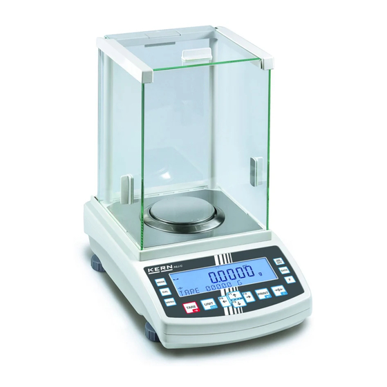
Page 4: Total View
2 Total View Windshield Weighing plate Protection ring Air bubble LCD display RS 232 interface Printer interface Connection mains adapter Foot screw Underfloor weighing device Foot... -
Page 5: Electric/Electronic Construction
3 Electric/Electronic Construction 3.1 Block Diagram Calibration Weight Unit (AEJ only) PRINT... -
Page 6: Whole Wiring
3.2 Whole Wiring Calibration Weight Unit (AEJ only) PRINT... -
Page 7: Troubleshooting
4 Troubleshooting 4.1 Troubleshooting Procedure... -
Page 8: Troubleshooting Table
4.2 Troubleshooting Table SYMPTOMS CAUSES & REMEDY No display lights on. 1. HT-DP board is defective. 2. AC adaptor is defective. 3. Inner connecting cord is not properly connected. [ u - Err ] or [ o - Err ] appears 1. - Page 9 SYMPTOMS CAUSES & REMEDY Corner Error is too much. 1. Mechanical unit is defective. Leaf spring is bent or twisted. 2. Pan base touch other parts. Display suddenly disappeared. 1. HT-DP board is defective. 2. AC adaptor is defective. 1. HT-DP board is defective. 2.
-
Page 10: Primary Check
4.3 Primary Check 1. Is there any wind around the site? Is there any oscillation? 2. Is anything under the pan base or the weighing pan? 3. Is the weighing pan the right one? Pan base When you attach or remove pan, pan base, windshield, take care no dust and/or liquid gets into the 4. -
Page 11: Check Of Electric/Electronic Parts
4.4 Check of Electric/Electronic Parts Check of HT-DP board... - Page 12 Check of input voltage TP0 – CN1-1 +9V~ +14V Power voltage in the circuit TP0 – TP1 +4.75V~ +5.25V TP0 – TP2 +3.15V~ +3.45V TP0 – IC12-O +7.6V~ +8.4V TP0 – IC13-OUT +2.65V~ +2.95V TP0 – D3 kasode +2.0V~ +2.4V TP0 –...
-
Page 13: Adjustment And Setting
5 Adjustment and Setting 5.1 Span Calibration (Adjustment with internal weight – AEJ) Procedure for adjustment (according to the operating instructions): Observe stable environment conditions. A warming-up time of approx. 8 hours for stabilisation is necessary. Function menu 1 setting: [ x CA. -
Page 14: Span Calibration (Adjustment With External Weight - Aes)
5.2 Span Calibration (Adjustment with external weight – AES) Procedure for adjustment (according to the operating instructions): Observe stable environment conditions. A warming-up time of approx. 8 hours for stabilisation is necessary. Function menu 1 setting: x CA. 3 Recommended adjustment weight: AES 120-4: 100g (E1) AES 220-4: 200g (E1) Press the CAL key... -
Page 15: Verification Switch And Seals
5.3 Verification switch and seals Prior to verification you will have move the calibration switch to verification position (See direction of arrow, fig. 1). In this position the display shows a bracket around the last display point. After verification the balance is sealed at the indicated positions. Seal of approval Seal of approval Move verification switch to... -
Page 16: Corner Error Adjustment
5.4 Corner Error Adjustment 1. Turn the adjusting legs to bring the bubble of the level to the center of the circle. 2. Put the full scale weight at “A” and push TARE key. 3. Move the weight to B and C. To adjust bolts R and L referring to the table below so that the corner error is within the specified range. -
Page 17: Linearity Adjustment
Set the verification switch to unlocked before doing the linearity adjustment (see chapter 5.3). Prior to verification, the verification switch must be moved into the verification position. 5.5.1 Linearity Adjustment of AES 120-4 and AEJ 120-4M 1. While pressing both , press to switch on the balance. -
Page 18: Linearity Adjustment Of Aes 220-4 And Aej 220-4M
5.5.2 Linearity Adjustment of AES 220-4 and AEJ 220-4M 1. While pressing both , press to switch on the balance. Release both keys when [ Ht00x ] appears (maintenance mode). 2. After a while, display changes to weight value (not the zero point). -
Page 19: Calibration Of Built-In Weight (Ref Cal) - Only Aej
5.6 Calibration of Built-In Weight (Ref Cal) – only AEJ [FWnm 2] 1. Hold key while key is pressed until is displayed (function menu 2). Release both keys. and press the key to display 2. While pressing first, press together and release both. After a while starts blinking. -
Page 20: Address Data Check And Re-Setting
5.7 Address Data Check and Re-setting a. Why do you need to re-set the address data, and in which case? “Address data” (coefficient memories) sometimes changes by noise in the environment or by static electricity. You can re-set the address data so as to bring back the balance to the initial factory condition. - Page 21 b. How to re-set the address data 1. While pressing both , press to switch on the balance. Release both keys when [ Ht00x ] appears (maintenance mode). 2. After a while, display changes to weight value (not the zero point). Press and hold until appears after displaying...
-
Page 22: Adjustment Of Overload Stopper
5.8 Adjustment of Overload Stopper 1. Enter “maintenance mode”. (see 5-5). 2. Put “stopper adjustment block” on the mechanical unit referring to the picture. 3. Adjust the level of the balance. Stopper adjustment block 4. Lose stopper fixing screw on the side of mechanical unit. 5. -
Page 23: Parts Replacement
6 Parts Replacement 6.1 How to Remove the Case 1. Remove the weighing pan and pan base. Weighing Pan Pan Base 2. Remove the WS Ring by turning it counter-clockwise. WS Ring 3. Remove the windshield. 4. Remove the upper case. -
Page 24: The Sequence Of Ht-Dp Board Replacement
6.2 The Sequence of HT-DP Board Replacement 1. How to replace HT-DP board a. Remove the case referring to chapter 6-1. b. Remove wires to tuning-fork sensor by welding solders at HT-DP board. c. Loose and remove fixing screws. d. Pull out all connectors, and remove HT-DP board. e. - Page 25 2. Adjustment after the replacement of HT-DP board Replacement with new HT-DP board See 5.7 Address data re-setting See 5.5 Linearity Adjustment Calibration of internal See 5.6 weight (AEJ only) See 5.1 / 5.2 Span Calibration See 4.3 Performance check...
-
Page 26: The Sequence Of Mechanical Unit Replacement
6.3 The Sequence of Mechanical Unit Replacement 1. How to remove the mechanical unit a. Open the case and remove nylon cramp fixing the connector cables. b. Pull out RS cable from LF board (power source board). c. Loose four screws, and remove the sensor cover. sensor cover Sensor cover d. - Page 27 f. Pull out the connectors and remove HT-DP board. g. Remove internal weight ASSY first, and then remove span weight. span weight internal weight ASSY h. Loose three screws, and remove the mechanical unit.
- Page 28 Replacement with new mechanical unit See 5.4 Corner Error Adjustment See 5.5 Linearity Adjustment Calibration of internal See 5.6 weight (AEJ only) See 5.1 / 5.2 Span Calibration Adjustment of overload See 5.8 stopper See 4.3 Performance check...
-
Page 29: The Sequence Of Tuning-Fork Sensor
2. Adjustment after the replacement of tuning-fork sensor Replacement with new mechanical unit See 5.4 Corner Error Adjustment See 5.5 Linearity Adjustment Calibration of internal See 5.6 weight (AEJ only) See 5.1 / 5.2 Span Calibration Adjustment of overload See 5.8 stopper See 4.3 Performance check... -
Page 30: Parts List
7 Parts List 7.1 Explosion Diagram... -
Page 31: Bill Of Material
7.2 Bill of Material POS. NO. DESCRIPTIONS PARTS Q'TY REMARKS LOWER CASE 270002I ADJUSTER AJM 200034I SHUTTER 3190P TM-166-3 22OM016 HT-DP PCB ASSY. 27AE001 HT-LCDBL PCB ASSY. 27OE001 BATTERY CASE 270004I HT-S PCB ASSY. 27AE002 HT-IO PCB ASSY. 27AE003 RS HOLDER 270007P D-SUB CODE ASSY. -
Page 32: Appendix
8 Appendix Table of Recommended Minimum Criteria for Adjustment Repeatability Corner Error Non-Linearity AES 120-4 0.0001g ±0.0005g ±0.0003g AEJ 120-4M AES 220-4 0.0001g ±0.0005g ±0.0003g AEJ 220-4M standard deviation 1/3 of full capacity loaded Repair Tool List 1. Mono-metal fixing block...
Need help?
Do you have a question about the AEJ and is the answer not in the manual?
Questions and answers