KERN ALJ Operating Instruction
Hide thumbs
Also See for ALJ:
- Operating manual (101 pages) ,
- Operating instructions manual (260 pages) ,
- Operating manual (78 pages)
Table of Contents
Advertisement
Available languages
Available languages
Quick Links
Betriebsanleitung
Operating instruction
Mode d'emploi
KERN ALJ/ALS/PLJ/PLS
Typ TALJG-A / TALSG-A / TPLJG-A / TPLSG-A
Version 1.2
2021-06
KERN & Sohn GmbH
Ziegelei 1
D-72336 Balingen
E-mail: info@kern-sohn.com
TALJG_A/TALSG_A/TPLJG_A/TPLSG_A-BA-def-2112
Phone: +49-[0]7433-9933-0
Fax: +49-[0]7433-9933-149
www.kern-sohn.com
Advertisement
Chapters
Table of Contents

Related Manuals for KERN ALJ


Summary of Contents for KERN ALJ
- Page 1 KERN & Sohn GmbH Ziegelei 1 Phone: +49-[0]7433-9933-0 D-72336 Balingen Fax: +49-[0]7433-9933-149 E-mail: info@kern-sohn.com www.kern-sohn.com Betriebsanleitung Operating instruction Mode d’emploi KERN ALJ/ALS/PLJ/PLS Typ TALJG-A / TALSG-A / TPLJG-A / TPLSG-A Version 1.2 2021-06 TALJG_A/TALSG_A/TPLJG_A/TPLSG_A-BA-def-2112...
- Page 2 Weitere Sprachversionen finden Sie online unter www.kern-sohn.com/manuals Další jazykové verze najdete na webu pod adresou www.kern-sohn.com/manuals Más versiones de idiomas se encuentran online bajo www.kern-sohn.com/manuals Vous trouverez d’autres versions de langue online sous www.kern-sohn.com/manuals Muut kieliversiot löytyvät osoitteesta www.kern-sohn.com/manuals Further language versions you will find online under www.kern-sohn.com/manuals Trovate altre versioni di lingue online in www.kern-sohn.com/manuals...
-
Page 3: Table Of Contents
Anschluss von Peripheriegeräten................34 Justierung ....................34 Justiermodus wählen ....................35 Automatische Justierung mit internem Gewicht ............36 Justierung mit internem Gewicht nach Drücken der CAL-Taste (Modelle ALJ / PLJ) 37 Justierung mit externem Gewicht ................38 Internes Justiergewicht überschreiben ..............39 Justierprotokoll anzeigen / drucken ................40 Eichung........................41... - Page 4 Nullstellen .........................43 Einfaches Wägen ......................44 Kapazitätsanzeige ....................44 Tarieren ........................45 Unterflurwägung .......................46 Setup-Menü ....................47 11.1 Wägeeinheiten (unit1 / unit2) ..................50 11.2 RS 232 ........................51 11.3 Baudrate ........................52 11.4 Auto Zero ........................53 11.5 Filter .........................54 11.6 Stabilität ........................54 11.7 Kontrast der Anzeige einstellen ................55 11.8 Hinterleuchtung der Anzeige ..................56 11.9...
- Page 5 Kleine Pannenhilfe ..................97 Ionisator (Factory option KERN ALJ-A03) ..........99 17.1 Allgemeines ......................99 17.2 Grundlegende Sicherheitshinweise ................99 17.3 Technische Daten ....................101 17.4 Geräteübersicht ...................... 101 17.5 Inbetriebnahme ....................... 102 17.6 Anwendungen ......................103 17.7 Reinigen ......................... 103 TALJG_A/TALSG_A/TPLJG_A/TPLSG_A-BA-d-2112...
-
Page 6: Technische Daten
1 Technische Daten KERN ALJ 160-4A ALJ 210-5A ALJ 200-5DA Artikelnummer /Typ TALJG 160-4-A TALJG 210-5-A TALJG 220-5-A Wägebereich (Max) 160 g 210 g 82 g / 220 g Ablesbarkeit (d) 0.1 mg 0.01 mg 0.01 mg/0.1 mg Reproduzierbarkeit 0.1 mg 0.05 mg... - Page 7 KERN ALJ 250-4A ALJ 310-4A ALJ 500-4A Artikelnummer /Typ TALJG 250-4-A TALJG 310-4-A TALJG 510-4-A Wägebereich (Max) 250 g 310 g 510 g Ablesbarkeit (d) 0.1 mg 0.1 mg 0.1 mg Reproduzierbarkeit 0.1 mg 0.1 mg 0.2 mg Linearität ± 0.3 mg ±...
- Page 8 KERN ALJ 160-4AM ALJ 250-4AM Artikelnummer /Typ TALJG 160-4M-A TALJG 250-4M-A Wägebereich (Max) 160 g 250 g Ablesbarkeit (d) 0.1 mg 0.1 mg Reproduzierbarkeit 0.1 mg 0.1 mg Linearität ± 0.3 mg ± 0.3 mg Eichwert (e) 1 mg 1 mg...
- Page 9 KERN ALS 160-4A ALS 250-4A Artikelnummer /Typ TALSG 160-4-A TALSG 250-4-A Wägebereich (Max) 160 g 250 g Ablesbarkeit (d) 0.1 mg 0.1 mg Reproduzierbarkeit 0.1 mg 0.1 mg Linearität ± 0.3 mg ± 0.3 mg Einschwingzeit (typisch) 4 sec. 4 sec.
- Page 10 KERN PLJ 420-3F PLJ 720-3A PLJ 1200-3A Artikelnummer /Typ TPLJG 420-3-A TPLJG 720-3-A TPLJG 1200-3-A Wägebereich (Max) 420 g 720 g 1200 g Ablesbarkeit (d) 0.001 g 0.001 g 0.001 g Reproduzierbarkeit 0.001 g 0.001 g 0.001 g Linearität ± 0.003 g ±...
- Page 11 KERN PLJ 2000-3A PLJ 4200-2F PLJ 6200-2A Artikelnummer /Typ TPLJG 2100-3-A TPLJG 4200-2-A TPLJG 6200-2-A Wägebereich (Max) 2100 g 4200 g 6200 g Ablesbarkeit (d) 0.001 g 0.01 g 0.01 g Reproduzierbarkeit 0.002 g 0.02 g 0.01 g Linearität ± 0.004 g ±...
- Page 12 KERN PLJ 720-3AM PLJ 6200-2AM Artikelnummer /Typ TPLJG 720-3M-A TPLJG 6200-2M-A Wägebereich (Max) 720 g 6200 g Ablesbarkeit (d) 0.001 g 0.01 g Reproduzierbarkeit 0.001 g 0.01 g Linearität ± 0.002 g ± 0.02 g Eichwert (e) 10 mg 100 mg...
- Page 13 KERN PLS 420-3F PLS 720-3A PLS 1200-3A Artikelnummer /Typ TPLSG 420-3-A TPLSG 720-3-A TPLSG 1200-3-A Wägebereich (Max) 420 g 720 g 1200 g Ablesbarkeit (d) 0.001 g 0.001 g 0.001 g Reproduzierbarkeit 0.001 g 0.001 g 0.001 g Linearität ± 0.004 g ±...
- Page 14 KERN PLS 4200-2F PLS 6200-2A Artikelnummer /Typ TPLSG 4200-2-A TPLSG 6200-2-A Wägebereich (Max) 4200 g 6200 g Ablesbarkeit (d) 0.01 g 0.01 g Reproduzierbarkeit 0.01 g 0.01 g Linearität ± 0.04 g ± 0.03 g Einschwingzeit (typisch) 3 sec. 2 sec.
- Page 15 PLS 20000-1F KERN PLS 8000-2A Artikelnummer /Typ TPLSG 8200-2-A TPLSG 20000-1-A Wägebereich (Max) 8200 g 20 kg Ablesbarkeit (d) 0.01 g 0.1 g Reproduzierbarkeit 0.01 g 0.1 g Linearität ± 0.04 g ± 0.4 g Einschwingzeit (typisch) 4 sec. 3 sec.
-
Page 16: Konformitätserklärung
** Kleinstes Teilegewicht beim Stückzählen - unter Normalbedingungen: Es herrschen unruhige Umgebungsbedingungen (Windzug, Vibrationen) Die Zählteile streuen 2 Konformitätserklärung Die aktuelle EG/EU-Konformitätserklärung finden Sie online unter: www.kern-sohn.com/ce Bei geeichten Waagen (= konformitätsbewerteten Waagen) ist die Konformitätserklärung im Lieferumfang enthalten. TALJG_A/TALSG_A/TPLJG_A/TPLSG_A-BA-d-2112... -
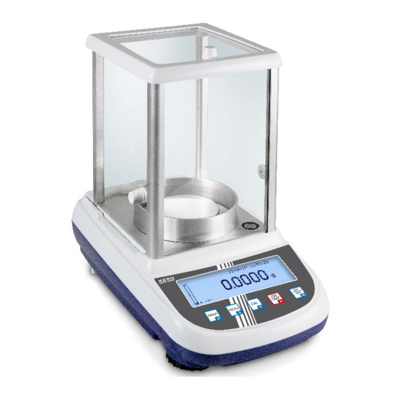
Page 17: Geräteübersicht
3 Geräteübersicht 3.1 Komponenten Vorderseite: Modell ALJ 200-5DA Modelle ALJ / ALS Pos. Bezeichnung Modell TALJG 210-5-A Glaswindschutz Windschutzring Wägeplatte Libelle Anzeige Tastatur Fußschraube Ionisator TALJG_A/TALSG_A/TPLJG_A/TPLSG_A-BA-d-2112... - Page 18 Modelle PLJ / PLS: Modell PLJ 2000-3A Abmessungen Wägeplatte Ø 110 mm Pos. Bezeichnung Pos. Bezeichnung Glaswindschutz Libelle Wägeplatte Abdeckung Glaswindschutz Anzeige Glaswindschutz Tastatur Wägeplatte Fußschraube Anzeige Libelle Fußschraube Tastatur TALJG_A/TALSG_A/TPLJG_A/TPLSG_A-BA-d-2112...
- Page 19 Modelle PLS Modell PLS 20000-1F Abmessungen Wägeplatte Ø 160 mm Abmessungen Wägeplatte 200 x 175 mm Pos. Bezeichnung Libelle Wägeplatte Anzeige Tastatur Fußschraube Abbildungsbeispiel mit eingebautem Ionisator(KERN ALJ-A03): TALJG_A/TALSG_A/TPLJG_A/TPLSG_A-BA-d-2112...
- Page 20 Rück- und Unterseite der Waagen 1. Wägeplatte 2. RS232C-Schnittstelle 3. Fussschrauben 4. Anschluss Netzadapter 5. Gehäuseschrauben (bei Modellen mit 4 Fußschrauben zu- nächst die beiden hinteren herausdrehen) 6. Unterflurwäge-einrich- tung 7. Transportsicherung (nur Modelle mit inter- nem Justiergewicht) TALJG_A/TALSG_A/TPLJG_A/TPLSG_A-BA-d-2112...
-
Page 21: Bedienungselemente
3.2 Bedienungselemente 3.2.1 Tastaturübersicht Taste Bezeichnung kurzer Tastendruck Langer Tastendruck bis das akustische Signal verstummt • Hauptmenü / • Setup-Menü aufrufen MENU-Taste/ Applikation aufrufen • Setup-Menü • Menüpunkte anwählen verlassen - vorwärts blättern • Ein-/Ausschalten • Hauptmenü / Applikation verlassen, ON/OFF-Taste zurück in den Wägemodus •... -
Page 22: Navigationstasten / Numerische Eingabe
3.2.2 Navigationstasten / Numerische Eingabe Taste Bezeichnung kurzer Tastendruck Langer Tastendruck • Ziffer erhöhen Navigationstaste • Im Menü vorwärts Dezimalpunkt setzen blättern • Ziffer verringern Wechsel Navigationstaste • Im Menü rückwärts Groß-/Kleinschreibung blättern • Ziffer positionieren Navigationstaste •... -
Page 23: Anzeigenübersicht
3.3 Anzeigenübersicht Pos. Bezeichnung Kapazitätsanzeige Stabilitätsanzeige Nullanzeige Wägewert Einheit Aktuelle Uhrzeit Aktuelles Datum Anzeige Beschreibung s. Kap. Kap. 9.3 Stabilitätsanzeige Kap. 9.3 Nullanzeige Waage befindet sich im Prozentbestimmungs-Modus Kap. 12.5 Waage befindet sich im Stückzähl-Modus Kap. 12.1 Oberer Grenzwert Kap. 12.4 Unterer Grenzwert Waage befindet sich im Dichtebestimmungs-Modus Kap. -
Page 24: Bedienerführung
3.4 Bedienerführung Bei einer gewählten Applikation werden Sie schrittweise durch die Anwendung ge- führt. Sprache wählbar (D, GB, F, IT. ESP, P; s. Kap. 11.11). Anzeigebeispiel „Stückzählen“ Pos. Bezeichnung Aktive Applikation Aktuelles Datum Aktuelle Uhrzeit Auszuführender Bedienungsschritt TALJG_A/TALSG_A/TPLJG_A/TPLSG_A-BA-d-2112... -
Page 25: Grundlegende Hinweise
Art und den Umfang dieser Prüfung zu definieren. Informationen bezüglich der Prüfmittelüberwachung von Waagen sowie der hierfür notwendigen Prüfgewichte sind auf der KERN- Homepage (www.kern-sohn.com) verfügbar. Im akkreditierten DKD- Kalibrierlaboratorium können bei KERN schnell und kostengünstig Prüfgewichte und Waagen kalibriert werden (Rückführung auf das nationale Normal). -
Page 26: Grundlegende Sicherheitshinweise
5.1 Hinweise in der Betriebsanleitung beachten Lesen Sie diese Betriebsanleitung vor der Aufstellung und In- betriebnahme sorgfältig durch, selbst dann, wenn Sie bereits über Erfahrungen mit KERN-Waagen verfügen. Alle Sprachversionen beinhalten eine unverbindliche Überset- zung. Verbindlich ist das deutsche Originaldokument. - Page 27 Evtl. vorgesehene Transportsicherungen wieder anbringen. Alle Teile z.B. Glaswindschutz, Wägeplatte, Netzteil etc. gegen Verrutschen und Beschädigung sichern. TALJG_A/TALSG_A/TPLJG_A/TPLSG_A-BA-d-2112...
- Page 28 Abbildungsbeispiel Analysenwaagen: TALJG_A/TALSG_A/TPLJG_A/TPLSG_A-BA-d-2112...
-
Page 29: Auspacken, Aufstellung Und Inbetriebnahme
7 Auspacken, Aufstellung und Inbetriebnahme 7.1 Aufstellort, Einsatzort Die Waagen sind so konstruiert, dass unter den üblichen Einsatzbedingungen zuver- lässige Wägeergebnisse erzielt werden. Exakt und schnell arbeiten Sie, wenn Sie den richtigen Standort für Ihre Waage wäh- len. Am Aufstellort folgendes beachten: •... -
Page 30: Auspacken Und Prüfen
7.2 Auspacken und Prüfen Gerät und Zubehör aus der Verpackung nehmen, Verpackungsmaterial entfernen und am vorgesehenen Arbeitsplatz aufstellen. Überprüfen, ob alle Teile des Lieferumfangs vorhanden und unbeschädigt sind. Lieferumfang/Serienmäßiges Zubehör • Waage, s. Kap. 3.1 • Netzadapter • Arbeitsschutzhaube • Betriebsanleitung •... - Page 31 Zusammenbau der Waage Modell ALJ 200-5DA Gitterwägeplatte einsetzen Windschutzring auflegen Modelle ALS/ALJ, d = 0,1 mg TALJG_A/TALSG_A/TPLJG_A/TPLSG_A-BA-d-2112...
- Page 32 Modelle PLS/PLJ, d = 1 mg Modelle PLS/PLJ, d = 100 mg Modelle PLS/PLJ, d = 10 mg TALJG_A/TALSG_A/TPLJG_A/TPLSG_A-BA-d-2112...
- Page 33 Nivellieren Eine exakte Ausrichtung und stabile Installation sind Voraussetzungen für wiederhol- bare Ergebnisse. Zum Ausgleich kleiner Unebenheiten oder Neigungen der Standflä- che lässt sich die Wage nivellieren. • Die Waage mit Fußschrauben nivellieren, bis sich die Luft- blase in der Libelle im vorgeschriebenen Kreis befindet. •...
-
Page 34: Netzanschluss
Kontrollieren, ob die Spannungsaufnahme der Waage richtig eingestellt ist. Die Waage darf nur an das Stromnetz angeschlossen werden, wenn die Angaben an der Waage (Aufkleber) und die ortsübliche Netzspannung identisch sind. Nur KERN-Originalnetzgeräte verwenden. Die Verwendung anderer Fabrikate bedarf der Zustimmung von KERN. Wichtig: ... -
Page 35: Bedienersprache Wählen
Waage unbedingt vom Netz getrennt werden. Verwenden Sie zu Ihrer Waage ausschließlich Zubehör und Peripheriegeräte von KERN, diese sind optimal auf Ihre Waage abgestimmt. 8 Justierung Da der Wert der Erdbeschleunigung nicht an jedem Ort der Erde gleich ist, muss jede Waage –... -
Page 36: Justiermodus Wählen
8.1 Justiermodus wählen Im Wägemodus MENU-Taste drücken und gedrückt halten bis das akustische Signal verstummt. Das Setup-Menü wird angezeigt. Mit den Navigationstasten Menüpunkt <Justiermodus> wählen. Mit PRINT-Taste bestätigen, die aktuelle Einstellung wird angezeigt. Mit den Navigationstasten gewünschte Einstellung wählen. Automatische Justierung mit internem Gewicht. - Page 37 8.2 Automatische Justierung mit internem Gewicht Werkseinstellung bei Modellen (ALJ / PLJ) in eichfähiger Einstellung Die automatische Justierung mit internem Gewicht wird automatisch gestartet, wenn die Waage • vom Netz getrennt wurde • nach Drücken von ON/OFF im Stand-by Modus •...
-
Page 38: Justierung Mit Internem Gewicht Nach Drücken Der Cal-Taste (Modelle Alj / Plj)
8.3 Justierung mit internem Gewicht nach Drücken der CAL-Taste (Modelle ALJ / PLJ) Voraussetzung: Menüeinstellung „Interne Justier.“, s. Kap. 8.1 Im Wägemodus CAL-Taste drücken, die Justierung läuft automatisch ab. Nach erfolgreicher Justierung kehrt die Waage automatisch in den Wägemo- dus zurück. -
Page 39: Justierung Mit Externem Gewicht
8.4 Justierung mit externem Gewicht • Werkseinstellung bei Modellen ALS / PLS • Bei Modellen ALJ /PLJ nur verfügbar in nicht eichfähiger Einstellung • Voraussetzung: Menüeinstellung „Externe Justier.“, s. Kap. 8.1 • Gewichtswert des empfohlenen Justiergewichtes siehe Kap. 1 „Techn. Daten“. -
Page 40: Internes Justiergewicht Überschreiben
8.5 Internes Justiergewicht überschreiben Die Überschreibung darf nur von einer Fachkraft mit fundierten Kenntnissen im Um- gang mit Waagen durchgeführt werden. Infos zu Prüfgewichten finden Sie im Internet unter http://www.kern-sohn.com Menüpunkt „Techn. Justierung“ aufrufen, s. Kap. 8.1. Zum Bestätigen PRINT-Taste drücken und gedrückt halten bis das akustische Signal verstummt. -
Page 41: Justierprotokoll Anzeigen / Drucken
Mit PRINT-Taste bestätigen, Datum, Uhrzeit, Art der Justierung und Abweichung der letzten Justierung werden angezeigt. Bei Anschluss eines optionalen Druckers werden diese Daten durch Drücken der PRINT -Taste ausgegeben. Ausdruckbeispiel (KERN YKB-01N): 27-08-20 10:41:17 Aktuelles Datum/Uhrzeit ID Waage:... -
Page 42: Eichung
8.7 Eichung Allgemeines: Nach der EU-Richtlinie 2014/31EU müssen Waagen geeicht sein, wenn sie wie folgt verwendet werden (gesetzlich geregelter Bereich): • Im geschäftlichen Verkehr, wenn der Preis einer Ware durch Wägung bestimmt wird. • Bei der Herstellung von Arzneimitteln in Apotheken sowie bei Analysen im me- dizinischen und pharmazeutischen Labor. - Page 43 Position Siegelmarke: Position der Siegelmarke (Modelle PLJ) TALJG_A/TALSG_A/TPLJG_A/TPLSG_A-BA-d-2112...
-
Page 44: Basisbetrieb
9 Basisbetrieb 9.1 Waage ein- und ausschalten Einschalten: Im Stand-by Modus ON/OFF-Taste drücken. Sobald die Gewichtsanzeige erscheint, ist die Waage wägebereit. Ausschalten: ON/OFF drücken. Die Waage wechselt in den Stand- by-Modus (Energiesparfunktion). Die Waage befindet sich im betriebsbereiten Zustand. ... -
Page 45: Einfaches Wägen
Nullanzeige abwarten, ggf. mit TARE-Taste nullstellen. Wägegut auflegen Warten bis die Stabilitätsanzeige [ ] erscheint. Wägeresultat ablesen. Bei Anschluss eines optionalen Druckers kann der Wägewert ausgegeben werden. Ausdruckbeispiele (KERN YKB-01N): 27-08-20 10:41:17 Aktuelles Datum/Uhrzeit Gewic.: 50.5773 g Wägewert 9.4 Kapazitätsanzeige Die Kapazitätsanzeige [] läuft von unten nach oben und schreitet in glei-... -
Page 46: Tarieren
9.5 Tarieren Das Eigengewicht beliebiger Wägebehälter lässt sich auf Knopfdruck wegtarieren, damit bei nachfolgenden Wägungen das Nettogewicht des Wägegutes angezeigt wird. Wägebehälter auf die Wägeplatte stellen. Warten bis die Stabilitätsanzeige [ ] erscheint, dann TARE-Taste drücken. „Tara“ wird angezeigt. ... -
Page 47: Unterflurwägung
9.6 Unterflurwägung Mit Hilfe der Unterflurwägung können Gegenstände, welche aufgrund ihrer Größe o- der Form nicht auf die Waagschale gestellt werden können, gewogen werden. Gehen Sie wie folgt vor: • Waage ausschalten. • Verschlussdeckel (1) am Waagenboden öffnen. • Haken zur Unterflurwägung vorsichtig und vollständig einhängen. •... -
Page 48: Setup-Menü
11 Setup-Menü Im Setup-Menü werden alle grundlegenden Einstellungen und Parameter, die sich auf den gesamten Betrieb der Waage auswirken, eingestellt. Navigation im Menü Einstieg ins Menü Im Wägemodus MENU-Taste drücken und gedrückt halten bis das akustische Signal verstummt. Das Setup-Menü wird angezeigt. Mit den Navigationstasten ... - Page 49 Menü-Übersicht: Menüpunkt Auswahl Beschreibung Einheit1 Gramm Einheit 2 Carat (siehe Kap. 11.1Fehler! Ver- Ounce weisquelle konnte nicht ge- Pound funden werden.) Pennyweights Troy Unze Grain tl 1 Hongkong-Teal tl 2 Singapur-Teal tl 3 Taiwan-Teal Momme RS 232 Fortlaufend Fortlaufende Ausgabe (siehe Kap.11.2) Ausgabe stabiler Wägewerte nach Drücken PRINT-Taste...
- Page 50 Kontrast der Anzeige Kontrast auswählen 1-15 (siehe Kap.11.7) Hintergrundbeleuchtung der Hinterleuchtung eingeschaltet Anzeige (siehe Kap. 11.8) Hinterleuchtung ausgeschaltet Hinterleuchtung schaltet sich 3 Sekunden nach Erreichen eines stabilen Wägewertes Auto automatisch ab. Bei Gewichtsänderung oder Tastendruck wird die Hinterleuchtung wieder automatisch eingeschaltet. AUTO OFF Deaktiviert AUTO-OFF ausgeschaltet...
-
Page 51: Wägeeinheiten (Unit1 / Unit2)
11.1 Wägeeinheiten (unit1 / unit2) Im Menü legen Sie fest, mit welchen Wägeeinheiten Sie arbeiten möchten. Durch die Wahl unterschiedlicher Einheiten (unit 1 und unit 2) können Sie das Wägeresultat gleichzeitig in zwei verschiedenen Wägeeinheiten (unit1 und unit2) anzeigen lassen. Mit der PRINT-Taste kann zwischen dem Wert der Wägeeinheit „unit 1“... - Page 52 Einheitenumschaltung: Im Wägemodus PRINT-Taste drücken und gedrückt halten bis das akustische Signal verstummt, dann Taste loslassen. Einheit 1 Einheit 2 • Beim Einschalten mit der ON/OFF-Taste aus dem Stand-by Modus startet die Waage mit der zuletzt verwendeten Einheit. • Nach Trennung vom Netz startet die Waage mit „Einheit 1“. 11.2 RS 232 ...
-
Page 53: Baudrate
Anzeige Beschreibung Fortlaufend Fortlaufende Datenausgabe Ausgabe stabiler Wägewerte nach Print-Taste Drücken der PRINT-Taste Nicht dokumentiert Nicht dokumentiert Für GLP-konforme Ausdrucke nach Drü- cken von PRINT diese Einstellung ver- Print-Taste - GLP wenden Nicht dokumentiert Nicht dokumentiert Auswahl mit PRINT-Taste übernehmen, die Waage kehrt zurück ins Menü. ... -
Page 54: Auto Zero
11.4 Auto Zero Unter diesem Menüpunkt kann die automatische Nullpunktkorrektur ein- oder ausge- schaltet werden. Im eingeschalteten Zustand wird der Nullpunkt bei Drift oder bei Verschmutzungen automatisch korrigiert. Hinweis: Werden kleine Mengen vom Wägegut entnommen oder zugeführt, so können durch die in der Waage vorhandene „Stabilitätskompensation“... -
Page 55: Filter
11.5 Filter Unter diesem Menüpunkt kann die Waage an bestimmte Umgebungsbedingungen und Messzwecke angepasst werden. Mit den Navigationstasten Menüpunkt <Filter> wählen. Mit PRINT-Taste bestätigen, die aktuelle Einstellung wird angezeigt. Mit den Navigationstasten gewünschte Einstellung wählen. Anzeige Beschreibung Filter 1... -
Page 56: Kontrast Der Anzeige Einstellen
Mit den Navigationstasten gewünschte Einstellung wählen. Anzeige Beschreibung Stabiliät 1 Stillstandskontrolle schnell - sehr ruhiger Aufstellungsort Stabiliät 2 Stillstandskontrolle schnell + genau - ruhiger Aufstellungsort Stabiliät 3 Stillstandskontrolle genau - unruhiger Aufstellungsort Auswahl mit PRINT-Taste übernehmen, die Waage kehrt zurück ins Menü. ... -
Page 57: Hinterleuchtung Der Anzeige
11.8 Hinterleuchtung der Anzeige Mit den Navigationstasten Menüpunkt <Hintergrundbeleuchtung> wählen. Mit PRINT-Taste bestätigen, die aktuelle Einstellung wird angezeigt. Mit den Navigationstasten gewünschte Einstellung wählen. Anzeige Beschreibung Hinterleuchtung schaltet sich 3 Sekunden nach Errei- chen eines stabilen Wägewertes automatisch ab. Bei Auto Gewichtsänderung oder Tastendruck wird die Hinter- leuchtung wieder automatisch eingeschaltet... -
Page 58: Uhrzeit Und Datum Einstellen
Anzeige Beschreibung Deaktiviert AUTO-OFF ausgeschaltet 2 Minuten AUTO-OFF nach 2 Minuten ohne Gewichtsänderung 5 Minuten AUTO-OFF nach 5 Minuten ohne Gewichtsänderung 15 Minuten AUTO-OFF nach 15 Minuten ohne Gewichtsänderung Auswahl mit PRINT-Taste übernehmen, die Waage kehrt zurück ins Menü. ... -
Page 59: Sprache Bedienerführung
11.11 Sprache Bedienerführung Mit den Navigationstasten Menüpunkt <Sprache> wählen. Mit PRINT-Taste bestätigen, die aktuelle Einstellung wird angezeigt. Mit den Navigationstasten gewünschte Einstellung wählen. Sprache Deutsch Français Español Português English Italiano Auswahl mit PRINT-Taste übernehmen, die Waage kehrt zurück ins Menü. ... -
Page 60: Hauptmenü „Applikationen
12 Hauptmenü „Applikationen“ Navigation im Menü: Im Wägemodus MENU-Taste drücken. Einstieg ins Menü Das Hauptmenü wird angezeigt. Menüpunkte an- Mit den Navigationstasten lassen sich die einzelnen Menü- wählen punkte der Reihe nach anwählen. Der Cursor (►) links neben dem Text zeigt den aktiven Menüpunkt an. Einstellungen Ausgewählten Menüpunkt mit PRINT-Taste bestätigen, die ak- ändern... -
Page 61: Stückzählen
12.1 Stückzählen Die Applikation <Stückzählen> ermöglicht Ihnen, mehrere auf die Wägeplatte gelegte Teile zu zählen. Bevor die Waage Teile zählen kann, muss sie das durchschnittliche Stückgewicht, die so genannte Referenz kennen. Dazu muss eine bestimmte Anzahl der zu zählen- den Teile aufgelegt werden. Die Waage ermittelt das Gesamtgewicht und teilt es durch die Anzahl der Teile, die so genannte Referenzstückzahl. - Page 62 Mit PRINT-Taste bestätigen. Sobald das Wägeresultat stabil ist, wird das ermittelte durchschnittliche Stückge- wicht als Referenzgewicht übernommen. Das aktuell aufgelegte Gewicht „G“, das Referenzgewicht „AUW“ und die Stückzahl „St.“ werden angezeigt. Referenzgewicht abnehmen. Die Waage befindet sich nun im Stückzähl-Modus und zählt alle Teile, die sich auf der Wägeplatte befinden.
- Page 63 Nachdem die Referenz ermittelt wurde, die zu zählenden Teile auflegen. Das ak- tuell aufgelegte Gewicht „G“, das Referenzgewicht „AUW“ und die ermittelte Stückzahl „St.“ werden angezeigt. Bei Anschluss eines optionalen Druckers kann der Wägewert ausgegeben wer- den. Ausdruckbeispiel (KERN YKB-01N): 27-08-20 10:41:17 Aktuelles Datum/Uhrzeit St.: Ermittelte Stückzahl Gewic.
-
Page 64: Numerische Eingabe Des Referenzgewichts
12.1.2 Numerische Eingabe des Referenzgewichts Falls das Stückgewicht (Referenz) bekannt ist, kann dieses direkt eingegeben wer- den. Da die Waage bei dieser Methode keine Referenz ermitteln muss, befindet sich die Waage nach Bestätigung des Referenzstückgewichts direkt im Stückzählmodus. Mit den Navigationstasten Applikation <Stückzählen>wählen und mit PRINT- Taste bestätigen, die aktuell eingestellte Referenzstückzahl wird angezeigt. -
Page 65: Automatische Referenzoptimierung
12.1.3 Automatische Referenzoptimierung Um die Zählgenauigkeit zu verbessern kann durch Auflegen weiterer Teile die Refe- renz optimiert werden. Bei jeder Referenzoptimierung wird das Referenzgewicht neu berechnet. Da die zusätzlichen Teile die Basis für die Berechnung vergrößern wird auch die Referenz genauer. ... -
Page 66: Dichtebestimmung Mit Hilfe Der Unterflurwägeinrichtung
Die Dichtebestimmung erfolgt entweder mit Hilfe der Unterflurwägeinrichtung oder ei- nes Dichtebestimmungssets. Der Einsatz eines optional erhältlichen Dichtebestimmungsset erleichtert Ihnen die Arbeit bei der Durchführung einer Dichtestimmung Analysenwaagen KERN YDB-03 Präzisionswaagen [d] = 0,001 g KERN ALT-A02 Präzisionswaagen [d] = 0,01 g KERN PLT-A01 12.2.1 Dichtebestimmung von Feststoffen mit Hilfe der... - Page 67 Mit den Navigationstasten (s. Kap. 3.2.2) aktuelle Dichte der Messflüssigkeit ein- geben. Für Wasser siehe nachfolgende Dichtetabelle. Mit PRINT-Taste bestätigen, die Anzeige zur Bestimmung „Gewicht in Luft“ wird angezeigt. Probe mit der Aufhängevorrichtung an den Unterflurhaken hängen. Stabilitätsan- zeige abwarten, den Gewichtswert mit PRINT-Taste übernehmen.
- Page 68 Bei Anschluss eines optionalen Druckers kann mit PRINT der Anzeigenwert aus- gegeben werden. Ausdruckbeispiel (KERN YKB-01N): 07-09-11 11:14:57 d: 8.0700 g/cm Sind bei der Dichtebestimmung Fehler aufgetreten wird „d-----„ angezeigt. Zurück in den Dichtebestimmungsmodus, MENU-Taste drücken. Zurück in den Wägemodus, ON/OFF-Taste drücken.
- Page 69 Dichtetabelle für Flüssigkeiten Dichte ρ [g/cm Temperatur [°C] Wasser Ethanol Methanol 0.9997 0.7978 0.8009 0.9996 0.7969 0.8000 0.9995 0.7961 0.7991 0.9994 0.7953 0.7982 0.9993 0.7944 0.7972 0.9991 0.7935 0.7963 0.9990 0.7927 0.7954 0.9988 0.7918 0.7945 0.9986 0.7909 0.7935 0.9984 0.7901 0.7926 0.9982 0.7893...
-
Page 70: Dichtebestimmung Von Flüssigkeiten
12.2.2 Dichtebestimmung von Flüssigkeiten Bei der Dichtebestimmung von Flüssigkeiten wird ein Senkkörper verwendet, dessen Dichte bekannt ist (optional erhältlich). Der Senkkörper wird zuerst in Luft und an- schließend in der Flüssigkeit gewogen, deren Dichte zu bestimmen ist. Aus der Ge- wichtsdifferenz resultiert der Auftrieb, aus dem die Software die Dichte berechnet. - Page 71 Sind bei der Dichtebestimmung Fehler aufgetreten wird „d-----„ angezeigt. Bei Anschluss eines optionalen Druckers kann mit PRINT der Anzeigenwert aus- gegeben werden. Ausdruckbeispiel (KERN YKB-01N): 07-09-11 11:14:57 d: 0.9984 g/cm Zurück in den Dichtebestimmungsmodus, MENU-Taste drücken.
-
Page 72: Rezeptieren
12.3 Rezeptieren Die Rezeptur-Funktion ermöglicht das Einwägen von Komponenten, die in einem be- stimmten Verhältnis zueinander stehen. Zur Kontrolle kann das Gewicht aller Kompo- nenten, sowie das Gesamtgewicht (TOT) ausgedruckt werden. Die Waage arbeitet mit einem getrennten Speicher für das Gewicht des Wägebehäl- ters und der Rezepturbestandteile. - Page 73 Nach Bedarf weitere Komponenten (max. 99) wie vorhergehend beschrieben ein- wägen. Rezepturvorgang abschließen Mit PRINT-Taste drücken und gedrückt halten bis das akustische Signal ver- stummt. Das Gesamtgewicht (TOT:) aller Komponenten wird angezeigt und an den Drucker ausgegeben. Ausdruckbeispiel (KERN YKB-01N): 07-08-20 11:14:57 Datum / Uhrzeit Manuell Rezeptur-Modus 15.00 g...
-
Page 74: Rezepte Definieren Und Abarbeiten
12.3.1 Rezepte definieren und abarbeiten Die Waage verfügt über einen internen Speicher für komplette Rezepturen mit allen Komponenten und den dazugehörigen Parametern (z. B. Rezeptname, Komponen- tenname und Gewicht, Toleranzen). Beim Abarbeiten einer Rezeptur führt Sie die Waage Schritt für Schritt durch das Einwägen der Komponenten. Rezept definieren: Im Speicher können maximal 99 Rezepte mit jeweils bis zu 20 Komponenten abge- legt werden können. - Page 75 3. Mit PRINT-Taste bestätigen. Die Anzeige zur Eingabe des ersten Komponenten- Namens erscheint. 4. Mit den Navigationstasten (s. Kap. 0) Komponenten-Name eingeben (max. 11 Zeichen). 5. Mit PRINT-Taste bestätigen. Die Anzeige zur Eingabe der Menge erscheint. 6. Mit den Navigationstasten (s. Kap. 3.2.2)) Menge eingeben. 7.
- Page 76 10. Den positiven Toleranzwert eingeben: Bsp.: 5 % 11. Mit PRINT-Taste bestätigen. 12. Zur Eingabe weiterer Komponenten (max. 20) jeweils Schritt 3 – 11 wiederho- len. 13. Nach Eingabe aller Komponenten mit der ON/OFF-Taste den Rezeptureingabe- Modus verlassen. Zurück in den Wägemodus, ON/OFF-Taste erneut drücken. TALJG_A/TALSG_A/TPLJG_A/TPLSG_A-BA-d-2112...
- Page 77 Rezepte aufrufen und abarbeiten: Nach Aufrufen eines abgespeicherten Rezeptes ist die Waage sofort für das Einwä- gen der Komponenten bereit. Name und Sollwert, Toleranz und Multiplikationsfaktor der jeweiligen Komponente werden angezeigt. Mit den Navigationstasten Menüpunkt <Rezeptieren> wählen. Mit PRINT-Taste bestätigen. bzw.
- Page 78 Mit den Navigationstasten gewünschten Multiplikationsfaktor eingeben. 1 = Rezeptmenge einfach 2 = Rezeptmenge doppelt 3 = Rezeptmenge dreifach etc. Mit PRINT-Taste ausgewählten Faktor bestätigen: Beispiel für Faktor 1 Toleranzwert Gesamtgewicht aller Komponenten Sollwert der Komponente Gesamtgewicht aller Komponenten Toleranzanzeige Übersicht Toleranzanzeige: Bsp.: Toleranz -10.0 % bis +5.0 %...
- Page 79 Die Anzeige zur Einwaage der ersten Komponente erscheint. Bei Einsatz eines Wägebehälters tarieren. Einwaage starten. Wenn der Sollwert erreicht ist, erscheint rechts neben der Kapazitätsanzeige „OK“. Wird der Sollwert unter- (-) oder überschritten (+) erscheint in der Anzeige nach Drücken der PRINT-Taste „Err 10“.
- Page 80 Ausdruckbeispiel (KERN YKB-01N): 07-09-20 11:14:57 Pudding Name Rezept 10.00 g Einwaage 1. Komponente Kakao Name 1. Komponente 70.00 g Einwaage 2. Komponente Zucker Name 2. Komponente 0.50 g Einwaage 3. Komponente Stärke Name 3. Komponente 80.50 g Gesamtgewicht Zurück in den Rezeptur-Modus, ON/OFF-Taste drücken und nächstes Rezept starten.
- Page 81 Beispiel für Faktor 2: Gewünschtes Rezept, wie oben beschrieben aufrufen Mit PRINT-Taste bestätigen, die erste Komponente, ihr Sollwert, sowie der nega- tive und der positive Toleranzwert werden angezeigt. Mit den Navigationstasten können alle Komponenten nebst Sollwert und Toleranzwerten angezeigt wer- den.
- Page 82 Wenn das Sollgewicht erreicht ist, PRINT-Taste drücken. Es erscheint kurz „War- ten“ gefolgt von „Tara“. Danach geht die Anzeige auf „G=0“ und die Anzeige zur Einwaage der zweiten Komponente erscheint. Der Sollwert beträgt nun „40.000 g“. Einwaage starten. Wenn der Sollwert er- reicht ist, erscheint rechts neben der Kapazitätsanzeige „OK“.
-
Page 83: Kontrollwägen
12.4 Kontrollwägen Mit der Applikation <Kontrollwägen> können Sie einen oberen und einen unteren Grenzwert festlegen und damit sicherstellen, dass das eingewogene Wägegut genau innerhalb der festgelegten Toleranzgrenzen liegt. Die Toleranzmarke () und ein Signalton (wählbar) zeigen an, ob das Wägegut sich innerhalb der zwei Toleranzgrenzen befindet. - Page 84 Einstellungen Mit den Navigationstasten Menüpunkt <Checkweighing> wählen. Mit PRINT-Taste bestätigen, die Anzeige zur Eingabe des unteren Grenzwertes erscheint. Mit den Navigationstasten (s. Kap. 3.2.2) unteren Grenzwert z. B. 9.00 g einge- ben. Mit PRINT-Taste bestätigen, die Anzeige zur Eingabe des oberen Grenzwertes er- scheint.
- Page 85 Wägegut innerhalb Wägegut über vorgegebener Toleranz vorgegebener Toleranz vorgegebener Toleranz Bei Anschluss eines optionalen Druckers kann mit PRINT der Anzeigenwert aus- gegeben werden. Ausdruckbeispiele (KERN YKB-01N): Wägegut unter Wägegut innerhalb Wägegut über vorgegebener Toleranz vorgegebener Toleranz vorgegebener Toleranz 23-08-20...
-
Page 86: Prozentbestimmung
Wägegut auflegen, die Resultatanzeige erscheint. Gewicht der Probe in Prozent Gewicht der Probe in Gramm BEZ: Referenzgewicht (100%) Bei Anschluss eines optionalen Druckers kann der Anzeigenwert ausgegeben werden. Ausdruckbeispiel (KERN YKB-01N): 07-09-20 11:14:57 Proz. 49.95 % Gewicht der Probe in Prozent Gewic. : 9.990 g... -
Page 87: Numerische Eingabe Des Referenzgewichts
Wägegut auflegen, die Resultatanzeige erscheint. Gewicht der Probe in Prozent Gewicht der Probe in Gramm BEZ: Referenzgewicht (100%) Bei Anschluss eines optionalen Druckers kann der Anzeigenwert ausgegeben werden. Ausdruckbeispiel (KERN YKB-01N): 07-09-20 11:14:57 Proz. 49.95 % Gewicht der Probe in Prozent Gewic. : 9.990 g... -
Page 88: Tierwägen
Wägegut auflegen und PRINT-Taste drücken. In der Anzeige läuft ein „Count- down“ der eingestellten Messdauer. Der Mittelwert der Wägeresultate wird angezeigt und bleibt in der Anzeige stehen. Bei Anschluss eines optionalen Druckers kann der Anzeigenwert ausgegeben werden. Ausdruckbeispiel (KERN YKB-01N): 07-09-20 11:14:57 Zeit = 20 Sek Messdauer 20.0052 g... -
Page 89: Spitzenwertfunktion
Der Spitzenwert bleibt solange in der Anzeige stehen, bis die TARE-Taste ge- drückt wird. Danach ist die Waage für weitere Messungen bereit. Bei Anschluss eines optionalen Druckers kann der Anzeigenwert ausgegeben werden. Ausdruckbeispiel (KERN YKB-01N): 07-09-20 11:14:57 Max.: 20.0356 g Spitzenwert Zurück in den Wägemodus:... -
Page 90: Glp Funktion (Gute Laborpraxis)
12.8 GLP Funktion (Gute Laborpraxis) In den Einstellungen von „GLP“ werden die Informationen definiert, welche auf den Messprotokollen ausgegeben werden. Mit den Navigationstasten Menüpunkt <GLP> wählen. Mit PRINT-Taste bestätigen. Die Anzeige zur Eingabe der Waagenidentifikations- nummer erscheint. ... - Page 91 Für GLP-konforme Ausdrucke Menüeinstellung „PRINT-Taste_GLP“ aktivie- ren, s. Kap. 11.2 Ausdruckbeispiel (KERN YKB-01N): 07-09-20 11:14:57 ID Waage: TEST 1 ID User: G.L.P. Parameter Mustermann ID Projekt: Gewic. 199.991 g Wägedaten Unterschrift G.L.P. Parameter TALJG_A/TALSG_A/TPLJG_A/TPLSG_A-BA-d-2112...
-
Page 92: Rs 232C Schnittstelle
Für die Kommunikation zwischen Waage und Drucker müssen folgende Bedingun- gen erfüllt sein: • Waage mit einem geeigneten Kabel mit der Schnittstelle eines Druckers ver- binden. Der fehlerfreie Betrieb ist nur mit dem entsprechenden KERN-Schnitt- stellenkabel sichergestellt. • Baudrate von Waage und Drucker müssen übereinstimmen, siehe Kap. 11.3. -
Page 93: Schnittstelle
13.3 Schnittstelle • Waage - PC 25-polig Waage Balance side nec- Connector 25 Pins • Waage - PC 9-polig Waage Balance side side • Waage - Drucker Drucker Waage Input data Busy signal TALJG_A/TALSG_A/TPLJG_A/TPLSG_A-BA-d-2112... -
Page 94: Drucker Anschließen
Waage und Drucker ausschalten. Waage mit einem geeigneten Kabel mit der Schnittstelle eines Druckers verbinden. Der fehlerfreie Betrieb ist nur mit dem entsprechenden KERN-Schnittstellenka- bel (Option) sichergestellt. Waage und Drucker einschalten. • Kommunikationsparameter von Waage und Drucker müssen übereinstim- men;... - Page 95 Zählen (nur Fernsteuerbefehl) Anzahl Teile 1°. 2° 3° 4° 5° 6° 7° 8° 9° 10° 11° 12° 13° 14° 15° 16° Stückzahl Leerzeichen Gewicht der aufgelegten Teile 1°. 2° 3° 4° 5° 6° 7° 8° 9° 10° 11° 12° 13° 14° 15° 16° 17° 18° 19° 20° Gewicht space Wägewert...
-
Page 96: Fernsteuerbefehle
Tierwägen (nur Fernsteuerbefehl) Zeit 1° 2° 3° 4° 5° 6° 7° 8° 9° 10° 11° 12° 13° 14° 15° 16° 17° 18° Zeit Leerz. Leerzeichen Zeitwert Sek. Leerzeichen Durchschnittswert 1°. 2° 3° 4° 5° 6° 7° 8° 9° 10° 11° 12° 13° 14° 15° 16° 17° 18° Durchschnitt Leerzeichen Durchschnittl. -
Page 97: Fehlermeldungen
Lose Probenreste/Pulver können vorsichtig mit einem Pinsel oder Handstaubsauger entfernt werden. Verschüttetes Wägegut sofort entfernen. 15.2 Wartung, Instandhaltung Das Gerät darf nur von geschulten und von KERN autorisierten Servicetechni- kern geöffnet werden. Vor dem Öffnen vom Netz trennen. TALJG_A/TALSG_A/TPLJG_A/TPLSG_A-BA-d-2112... -
Page 98: Entsorgung
15.3 Entsorgung Die Entsorgung von Verpackung und Gerät ist vom Betreiber nach gültigem nationa- lem oder regionalem Recht des Benutzerortes durchzuführen. 16 Kleine Pannenhilfe Bei einer Störung im Programmablauf sollte die Waage kurz ausgeschaltet und vom Netz getrennt werden. Der Wägevorgang muss dann wieder von vorne begonnen werden. - Page 99 Hinweis gemäß Batterieverordnung – BattV Nur gültig für Deutschland! Im Zusammenhang mit dem Vertrieb von Batterien und Akkus sind wir als Händler gemäß Batterieverordnung verpflichtet, Endverbraucher auf folgendes hinzuweisen: Endverbraucher sind zur Rückgabe gebrauchter Batterien/Akkus gesetzlich ver- pflichtet. Batterien/Akkus können nach Gebrauch in kommunalen Sammelstellen o- der im Handel zurückgegeben werden.
-
Page 100: Ionisator (Factory Option Kern Alj-A03)
17 Ionisator (Factory option KERN ALJ-A03) (bei Gerät TALJG 210-5-A Ionisator als Standard) 17.1 Allgemeines Der Ionisator besitzt mit Hochspannung versorgte leitfähige Spitzen, die durch Koro- naentladung in der unmittelbaren Umgebung positiv und negativ geladene Ionen er- zeugen. Diese werden vom elektrostatisch geladenen Wägegut angezogen und neut- ralisieren damit die störende elektrostatische Ladung. - Page 101 Schäden durch Fallenlassen, Vibration oder Schock verhindern, siehe Aufkleber an der linken Seite. Nur das Original-Netzteil verwenden. Der aufgedruckte Spannungswert muss mit der örtlichen Spannung übereinstimmen. Verletzungsgefahr, die Spitzen der Ionenquelle sind sehr scharf schnei- dend Der Ionisator erzeugt giftiges Ozon, auf ausreichende Belüftung achten. Bei Instandhaltungs- und Reinigungsarbeiten Ionisator vom Netz tren- nen.
-
Page 102: Technische Daten
17.3 Technische Daten Abstand ca. 5 – 40 cm „Probe-Ionenquelle“ Ozonkonzentration 0 ~ 0,05 ppm (2cm ab Ionenquelle) Gewicht 525 g Abmessungen [cm] 110 x 105 x 60 Umgebungsbedingungen 0 - 50 °C, 20 – 80 % Luftfeuchtigkeit (nicht kondensierend) Netzteil AC 100-240V, 50 / 60Hz Eingangspannung... -
Page 103: Inbetriebnahme
Anzeigenübersicht LED grün Ionisatorbetrieb Ionisator eingeschaltet LED rot Ionisatorbetrieb Continous Mode LED rot blinkend Ionisatorbetrieb In-time-mode 17.5 Inbetriebnahme Ionisator nur bei ausgeschaltetem Gerät mit Netzadapter verbinden. Ionisator mit einschalten. Der Ionisator befindet sich in der Betriebsart „Continous Mode“, die Betriebsdauer beträgt 8 Stunden. -
Page 104: Anwendungen
17.6 Anwendungen Die Verwendung des Ionisators ist nur in Kombination mit elektroni- schen Waagen vorgesehen! • Entladen von Festkörpern oder Wägebehältern. Bei eingeschaltetem Gebläse werden bessere Ionisierungsergebnisse erzielt, die Dauer zum Entladen der Probe wird verkürzt. • Entladen von pulverförmigen Proben. Entladung verhindert Aufwirbelung, Problem bei toxischen Proben. - Page 105 Adjustment mode selection ..................35 Automatic adjustment using the internal weight ............36 Adjustment using the internal weight after the Model CAL button is pressed (models ALJ/PLJ) ..........................37 Adjustment using the external weight ................38 Changing the weight of the internal calibration weight..........39 Adjustment report display/print ..................40...
- Page 106 Switching the scale on and off ..................42 Resetting ........................42 Ordinary weighing .....................43 Weighing range indicator ..................43 Taring ........................44 Weighing using the under-scales weighing hanger ...........45 Setup menu ....................46 11.1 Weight units (unit1/unit2) ..................49 11.2 RS-232 ........................50 11.3 Transmission speed ....................51 11.4 Auto zero ........................52 11.5...
- Page 107 15.3 Disposal ........................96 Help for any minor failures ................. 96 Ionizing unit (factory option for KERN ALJ-A03) ........97 17.1 General information ....................97 17.2 Basic safety instructions ...................97 17.3 Technical specification ....................99 17.4 Device overview ......................99 17.5 Start ........................100 17.6...
-
Page 108: Technical Specification
1 Technical specification KERN ALJ 160-4A ALJ 210-5A ALJ 200-5DA Product number / type TALJG 160-4-A TALJG 210-5-A TALJG 220-5-A Weighing range (Max) 160 g 210 g 82 g/220 g Interval (d) 0.1 mg 0.01 mg/0.1 mg 0.01 mg Reproducibility 0.1 mg... - Page 109 KERN ALJ 250-4A ALJ 310-4A ALJ 500-4A Product number / type TALJG 250-4-A TALJG 310-4-A TALJG 510-4-A Weighing range (Max) 250 g 310 g 510 g Interval (d) 0.1 mg 0.1 mg 0.1 mg Reproducibility 0.1 mg 0.1 mg 0.2 mg Linearity ±0.3 mg...
- Page 110 KERN ALJ 160-4AM ALJ 250-4AM Product number / type TALJG 160-4M-A TALJG 250-4M-A Weighing range (Max) 160 g 250 g Interval (d) 0.1 mg 0.1 mg Reproducibility 0.1 mg 0.1 mg Linearity ±0.3 mg ±0,3 mg Verification scale interval (e)
- Page 111 KERN ALS 160-4A ALS 250-4A Product number / type TALSG 160-4-A TALSG 250-4-A Weighing range (Max) 160 g 250 g Interval (d) 0.1 mg 0.1 mg Reproducibility 0.1 mg 0.1 mg Linearity ±0.3 mg ±0,3 mg Settling time (standard) Minimum part weight when counting...
- Page 112 KERN PLJ 420-3F PLJ 720-3A PLJ 1200-3A Product number / type TPLJG 420-3-A TPLJG 720-3-A TPLJG 1200-3-A Weighing range (Max) 420 g 720 g 1200 g Interval (d) 0.001 g 0.001 g 0.001 g Reproducibility 0.001 g 0.001 g 0.001 g Linearity ±0.003 g...
- Page 113 KERN PLJ 2000-3A PLJ 4200-2F PLJ 6200-2A Product number / type TPLJG 2100-3-A TPLJG 4200-2-A TPLJG 6200-2-A Weighing range (Max) 2100 g 4200 g 6200 g Interval (d) 0.001 g 0.01 g 0.01 g Reproducibility 0.002 g 0.02 g 0.01 g Linearity ±0.004 g...
- Page 114 KERN PLJ 720-3AM PLJ 6200-2AM Product number / type TPLJG 720-3M-A TPLJG 6200-2M-A Weighing range (Max) 720 g 6200 g Interval (d) 0.001 g 0.01 g Reproducibility 0.001 g 0.01 g Linearity ±0.002 g ±0,02 g Verification scale interval (e)
- Page 115 KERN PLS 420-3F PLS 720-3A PLS 1200-3A Product number / type TPLSG 420-3-A TPLSG 720-3-A TPLSG 1200-3-A Weighing range (Max) 420 g 720 g 1200 g Interval (d) 0.001 g 0.001 g 0.001 g Reproducibility 0.001 g 0.001 g 0.001 g Linearity ±0.004 g...
- Page 116 KERN PLS 4200-2F PLS 6200-2A Product number / type TPLSG 4200-2-A TPLSG 6200-2-A Weighing range (Max) 4200 g 6200 g Interval (d) 0.01 g 0.01 g Reproducibility 0.01 g 0.01 g Linearity ±0.04 g ±0,03 g Settling time (standard) Minimum part weight when...
- Page 117 PLS 20000-1F KERN PLS 8000-2A Product number / type TPLSG 8200-2-A TPLSG 20000-1-A Weighing range (Max) 8200 g 20 kg Interval (d) 0.01 g 0.1 g Reproducibility 0.01 g 0.1 g Linearity ±0.04 g ±0,4 g Settling time (standard) Minimum part weight when...
-
Page 118: Declaration Of Conformity
There is diversification of the counted pieces’ weight 2 Declaration of Conformity The valid Declaration of Conformity EC/UE is available at: www.kern-sohn.com/ce For verified scales (= the ones subject to the conformity assessment procedure), the Declaration of Conformity is included in the delivery scope. -
Page 119: Device Overview
3 Device overview 3.1 Parts Front: Model ALJ 200-5DA Models ALJ/ALS Item Name Modell TALJG 210-5-A Glass wind breaker Wind breaker ring Scale plate Leveler Display Keyboard Leveling screw foot Ionisator TALJG_A/TALSG_A/TPLJG_A/TPLSG_A-BA-e-2112... - Page 120 Models PLJ/PLS: Model PLJ 2000-3A Scale plate dimensions Ø 110 mm Item Name Item Name Glass wind breaker Leveler Scale plate Cover of the glass wind breaker Display Glass wind breaker Keyboard Scale plate Leveling screw foot Display Leveler Leveling screw foot Keyboard TALJG_A/TALSG_A/TPLJG_A/TPLSG_A-BA-e-2112...
- Page 121 Models PLS Models PLS 20000-1F scale plate dimensions Ø 160 mm scale plate dimensions 200 x 175 mm Item Name Leveler Scale plate Display Keyboard Leveling screw foot Sample drawing with a ionizing unit installed (KERN ALJ-A03): TALJG_A/TALSG_A/TPLJG_A/TPLSG_A-BA-e-2112...
- Page 122 Scale back and bottom 1. Scale plate 2. RS-232C interface 3. Leveling screw foot 4. Power supply socket 5. Housing screws (in models with 4 leveling screw feet, first screw out both rear ones) 6. Equipment for the under-scales weighing hanger 7.
-
Page 123: Operating Controls
3.2 Operating controls 3.2.1 Keyboard overview Button Name Button pressing Pressing and holding the button until the sound is heard • Displaying the main / • Displaying the setup MENU application menu menu button • Menu item selection — • Leaving the setup scrolling forward menu •... -
Page 124: Navigation Buttons / Introducing The Numerical Value
3.2.2 Navigation buttons / Introducing the numerical value Button Name Button pressing Pressing and holding the button • Increasing the digit value Navigation • In the menu: scrolling Setting a decimal point button forward • Decreasing the digit value Navigation Changing to •... -
Page 125: Display Overview
3.3 Display overview Item Name Weighing range indicator Stabilization indicator Zero indicator Weighing value Unit Current time Current date Symbol Description see chapter Stabilization indicator chapter Zero indicator chapter The scale is in the percentage value determination mode 12.5 chapter The scale is in the piece count mode 12.1 chapter... -
Page 126: User Interface
3.4 User interface Once the application is downloaded, the operator is guided step by step. It is possible to select a language (D, GB, F, IT, ESP, P; see chapter 11.11). Display example “Piece count” Item Name Active application Current date Current time Operation carried out TALJG_A/TALSG_A/TPLJG_A/TPLSG_A-BA-e-2112... -
Page 127: Basic Instructions
KERN (www.kern-sohn.com). The reference weights and scales can be calibrated fast and for a low cost in the KERN calibration laboratory (against the national reference) approved by DKD (Deutsche Kalibrierdienst). -
Page 128: Basic Safety Instructions
5.1 Compliance with the instructions included in the user manual Before you set and start the device, read this user manual thoroughly even if you are familiar with KERN scales. All language versions contain non-binding translation. Only the original document in German is binding. - Page 129 Reinstall any transport locks, if present. Protect all the parts, e.g. glass wind breaker, scale plates, power supply etc. from slipping and damage. TALJG_A/TALSG_A/TPLJG_A/TPLSG_A-BA-e-2112...
- Page 130 Sample drawing for analytical scales: TALJG_A/TALSG_A/TPLJG_A/TPLSG_A-BA-e-2112...
-
Page 131: Unpacking, Positioning And Start-Up
7 Unpacking, positioning and start-up 7.1 Installation place, operation place The scales are designed to ensure reliable weighing results in standard operating conditions. The choice of a correct scale location ensures its accurate and fast operation. This is why you should follow the following rules in the location site: •... -
Page 132: Unpacking And Check
7.2 Unpacking and check Remove the device and accessories from the packaging, remove the packaging material and place the device in the target location. Check if all components included in the delivery are present and not damaged. Scope of delivery / standard accessories •... - Page 133 Scale installation Model ALJ 200-5DA Place the scale plate with the grate. Install the wind breaker ring. Models ALS/ALJ, d = 0.1 mg TALJG_A/TALSG_A/TPLJG_A/TPLSG_A-BA-e-2112...
- Page 134 Models PLS/PLJ, d = 1 mg Models PLS/PLJ, d = 100 mg Models PLS/PLJ, d = 10 mg TALJG_A/TALSG_A/TPLJG_A/TPLSG_A-BA-e-2112...
- Page 135 Leveling Accurate setting and stable installation are the conditions enabling to obtain repeatable results. Small unevenness or inclination of the base surface can be compensated by leveling the scale. • Level the scale using the leveling feet. The air bubble in the leveler must be present in the marked area.
-
Page 136: Power Supply
Check if the scale voltage is set correctly. The scale can be connected to the mains only when the voltage specified on the scale (sticker) and the local voltage are identical. Always use the original power supply by KERN. Using any other products requires KERN consent. Important information: ... -
Page 137: Operator Language Selection
Before you connect or disconnect any extra devices (printer, computer) to/from the data interface, the scale should always be disconnected from the mains. Use solely accessories and peripherals supplied by KERN with the scale, being perfectly compatible with it. 8 Adjustment... -
Page 138: Adjustment Mode Selection
8.1 Adjustment mode selection In the weighing mode press and hold the MENU button until the sound signal stops. The configuration menu is displayed. Using the navigation buttons , select the menu item <Calibration mode>. Confirm by pressing the PRINT button, the current setting will be displayed. -
Page 139: Automatic Adjustment Using The Internal Weight
8.2 Automatic adjustment using the internal weight Factory setting in the models in the verifiable setting (ALJ/PLJ) The automatic adjustment using the internal weight is started automatically: • when the scale was disconnected from the mains, • after the ON/OFF button is pressed in the stand-by mode, •... -
Page 140: Adjustment Using The Internal Weight After The Model Cal Button Is Pressed (Models Alj/Plj)
8.3 Adjustment using the internal weight after the Model CAL button is pressed (models ALJ/PLJ) Preliminary condition: Menu setting “Internal adjustment”, see chapter 8.1. In the weighing mode, press the CAL button, the adjustment will be carried out automatically. -
Page 141: Adjustment Using The External Weight
8.4 Adjustment using the external weight • Factory setting in ALS/PLS models • In ALJ/PLJ models it is available only in the verifiable setting. • Preliminary condition: Menu setting “External adjustment”, chapter 8.1. • The weight of the recommended adjustment weight, see chapter 1 “Technical Specification”. -
Page 142: Changing The Weight Of The Internal Calibration Weight
8.5 Changing the weight of the internal calibration weight This change can be carried out solely by a specialist holding thorough knowledge of handling scales. Information on reference weights can be found on the Internet at http://www.kern-sohn.com. Display the menu item “Technical adjustment”, see chapter 8.1. ... -
Page 143: Adjustment Report Display/Print
Confirm, pressing the PRINT button. The following will be displayed: date, time, adjustment type and deviation when compared to the most recent adjustment. After the optional printer is connected, the data can be printed by pressing the PRINT button. Sample printout (KERN YKB-01N): 27-08-20 10:41:17 Current date/time Balance ID:... -
Page 144: Verification
8.7 Verification General information: According to the Directive 2014/31/EU, the scales must be verified if they are used in the following way (legally determined scope): a) for commercial purposes when the goods’ price is determined by weighing them, b) to produce medications in pharmacies and also for analyses in medical and pharmaceutical laboratories, c) for official purposes, d) for manufacturing finished packagings. -
Page 145: Basic Mode
9 Basic mode 9.1 Switching the scale on and off Switching on: In the stand-by mode, press the ON/OFF button. The scale is ready to weigh immediately after the weight symbol is displayed. Switching off: Press the ON/OFF button. The scale will be switched to the stand-by mode (energy saving function). -
Page 146: Ordinary Weighing
Wait until the stabilization indicator is displayed [ ]. Read out the weighing result. Once the optional printer is connected, the weighing value can be printed. Sample printouts (KERN YKB-01N): 27-08-20 10:41:17 AM Current date/time Gewic.: 50.5773 g Weighing value 9.4 Weighing range indicator... -
Page 147: Taring
9.5 Taring The empty weight of any container used for weighing can be tared, pressing the button which results in displaying the net weight of the weighed material during consecutive weighing processes. Place the scale container on the scales plate. ... -
Page 148: Weighing Using The Under-Scales Weighing Hanger
9.6 Weighing using the under-scales weighing hanger Weighing using the under-scales weighing hanger enables to weigh any objects which cannot be placed on the scale plate because of their size or shape. Carry out the following steps: • Switch the scale off. •... -
Page 149: Setup Menu
11 Setup menu In the configuration menu, all the basic settings and parameters affecting the total scale operation are entered. Menu navigation Entering the menu In the weighing mode press and hold the MENU button until the sound signal stops. The configuration menu is displayed. - Page 150 Menu overview: Menu item Selection Description Unit 1 gram Unit 2 karat ounce see chapter 11.1) pound Pennyweight Ounce Troy Grain tl 1 Tael (Hong Kong) tl 2 Tael (Singapore) tl 3 Tael (Taiwan) Momme RS-232 Continuous Continuous data transfer see chapter 11.2) Sending the stable weighing value after the PRINT button...
- Page 151 Display contrast 1-15 Contrast selection (see chapter 11.7) Display backlight Backlight on (see chapter 11.8) Backlight off Automatic switch-off of the backlight 3 s after the stable weighing value is achieved. The Auto backlight will be switched on again automatically after the weight is changed or the button is pressed.
-
Page 152: Weight Units (Unit1/Unit2)
11.1 Weight units (unit1/unit2) Weight units which are to be available during operation can be specified in the menu. After different units (unit1 and unit2) are selected, the weighing result can be displayed in two weight units (unit1 and unit2) simultaneously. To switch between the values in weight “unit1”... - Page 153 Unit switching: In the weighing mode press and hold the PRINT button until the sound signal stops, then release the button. Unit 1 Unit 2 • When switching on from the stand-by mode using the ON/OFF button, the scale will be started with the unit used most recently. •...
-
Page 154: Transmission Speed
Symbol Description <Continuous> Continuous data transfer Sending the stable weighing value after the <On demand> PRINT button is pressed Sending data standard printer <Generic printer> following the remote control request. Sending data to the printer supporting the <Printer TLP> LP-50 protocol. setting used obtain... -
Page 155: Auto Zero
11.4 Auto zero This menu item enables to switch on or off the automatic zero point correction. In the switched on state, the deviation or zero point disturbance is corrected automatically. Tip: If the amount of the weighed material is reduced or increased significantly, the scale’s “stabilizing and compensating”... -
Page 156: Filter
11.5 Filter This menu item enables to adapt the scale to the specific environment conditions and measurement objectives. Using the navigation buttons , select the menu item <Filter>. Confirm by pressing the PRINT button, the current setting will be displayed. ... -
Page 157: Setting The Display Contrast
Using the navigation buttons , select the required setting. Symbol Description Stability 1 Fast stabilization check — very calm setting item Fast and accurate stabilization and check — calm setting Stability 2 item Stability 3 Accurate stabilization check — uncalm setting item ... -
Page 158: Display Backlight
11.8 Display backlight Using the navigation buttons , select the menu item <Backlight>. Confirm by pressing the PRINT button, the current setting will be displayed. Using the navigation buttons , select the required setting. Symbol Description Automatic switch-off of the backlight 3 s after the stable weighing value is achieved. -
Page 159: Setting Time And Date
Symbol Description Disabled AUTO-OFF function off Automatic switch off after 2 minutes with no weight 2 minutes change Automatic switch off after 5 minutes with no weight 5 minutes change Automatic switch off after 15 minutes with no weight 15 minutes change ... -
Page 160: User Interface Language
11.11 User interface language Using the navigation buttons , select the menu item <Language>. Confirm by pressing the PRINT button, the current setting will be displayed. Using the navigation buttons , select the required setting. Language Deutsch Français Español Português... -
Page 161: Main Menu "Applications
12 Main menu “Applications” Menu navigation: In the weighing mode, press the MENU button. Entering the menu The main menu is displayed. Selecting the Navigation buttons enable to select subsequent, individual menu items menu items. The active menu item is indicated by the cursor (►) to the left of the text. -
Page 162: Counting The Number Of Pieces
12.1 Counting the number of pieces The <Piece counting> application enables to count many pieces placed on the scale plate. Before it is possible to count pieces using the scale, you should determine the average weight of an individual part (unit weight), the so-called reference value. For that purpose, place a specific number of counted parts on it. - Page 163 Confirm, pressing PRINT. The determined average weight of an individual part will be assumed as the reference weight immediately after the weighing result is stabilized. The following will be displayed: the currently placed “G” weight, reference weight “AUW” and the number of pieces “St.”. ...
- Page 164 “G” weight, reference weight “AUW” and the determined number of pieces “St.”. Once the optional printer is connected, the weighing value can be printed. Sample printout (KERN YKB-01N): 23-08-20 9:35:17 Current date/time Determined number of pieces Weight: 200.0001 g...
-
Page 165: Introducing The Reference Weight In The Numerical Value
12.1.2 Introducing the reference weight in the numerical value If the unit weight (reference value) is known, it can be entered directly. As when using this method the scale need not determine the reference value, after the reference unit weight is confirmed the scale will be switched directly to the piece counting mode. -
Page 166: Automatic Optimization Of The Reference Value
12.1.3 Automatic optimization of the reference value To improve the counting accuracy, the reference value can be optimized by adding new pieces. For every reference value optimization, the reference weight will be recalculated. As the additional pieces increase the calculation base, the reference value also becomes more accurate. -
Page 167: Determining Density Using The Equipment For The Under-Scales Weighing Hanger
Density is determined using the equipment for the under-scales weighing hanger or a kit for the density determination. The optional density determination kit facilitates the density determination: analytical scales KERN YDB-03 precision scales [d] = 0,001 g KERN ALT-A02 precision scales [d] = 0,01 g KERN PLT-A01 12.2.1 Determining solid body density using the equipment for the... - Page 168 Using the navigation buttons (see chapter 3.2.2), enter the current density of the measurement liquid. For water, see the density table below. Confirm, pressing the PRINT button. The symbol will be displayed to determine the weight “Weigh in the air”. ...
- Page 169 After the optional printer is connected, the indication value can be printed by pressing the PRINT button. Sample printout (KERN YKB-01N): 23-08-20 11:14:57 8.0700 g/cm If there are any errors when determining the density, “d-----” will be displayed. Return to the density determination mode, pressing the MENU button.
- Page 170 Liquid density table Density ρ [g/cm Temperature [°C] Water Ethanol Methanol 0.9997 0.7978 0.8009 0.9996 0.7969 0.8000 0.9995 0.7961 0.7991 0.9994 0.7953 0.7982 0.9993 0.7944 0.7972 0.9991 0.7935 0.7963 0.9990 0.7927 0.7954 0.9988 0.7918 0.7945 0.9986 0.7909 0.7935 0.9984 0.7901 0.7926 0.9982 0.7893...
-
Page 171: Liquid Density Determination
12.2.2 Liquid density determination When determining the liquid density, the sinker of a known volume is used (available optionally). The sinker is first weighed in the air and then in the liquid, the density of which is to be determined. The hydrostatic lift stems from the weight difference which is converted into density by the software. - Page 172 If there are any errors when determining the density, “d-----” will be displayed. After the optional printer is connected, the indication value can be printed by pressing the PRINT button. Sample printout (KERN YKB-01N): 07-09-11 11:14:57 0.9984 g/cm Return to the density determination mode, pressing the MODE button.
-
Page 173: Formulation
12.3 Formulation The formulation function enables to weigh the ingredients in a specific ratio. To check, it is possible to print the weight of all ingredients and the total weight (TOT). When the scale is operated, the separate memory is used for the scale container weight and for the formula ingredients. - Page 174 (max. 99). Finishing the formulation process Press and hold the PRINT button until the sound signal stops. The total weight (TOT:) of all ingredients will be displayed and printed using the printer. Sample printout (KERN YKB-01N): 07-08-20 11:14:57 Date/time Manual Formulation mode 15.00 g...
-
Page 175: Formulation Defining And Implementation
12.3.1 Formulation defining and implementation The scale has an internal memory for complete formulations with all ingredients and pertinent parameters (e.g. the name of the formulation, name and weight of the ingredient, tolerances). When the formulation is implemented, the operator is guided by the scale step by step when weighing the ingredients. - Page 176 3. Confirm, pressing PRINT. The symbol will be displayed to enable to enter the name of the first ingredient. 4. Using the navigation buttons (see chapter 3.2.2), enter the ingredient name (max. 11 characters). 5. Confirm, pressing PRINT. The symbol will be displayed to enable to enter the quantity.
- Page 177 10. Enter the positive tolerance value. Example: 5% 11. Confirm, pressing PRINT. 12. To introduce further ingredients (max. 20), repeat steps 3–11 each time. 13. After all the ingredients are introduced, leave the formulation entering mode, by pressing the ON/OFF button. ...
- Page 178 Formulation displaying and implementation: After the saved formulation is triggered, the scale is immediately ready to weigh the ingredients. The following will be displayed: name and preset value, tolerance and the multiplication factor of every ingredient. Using the navigation buttons , select the menu item <Formulation>. ...
- Page 179 Using the navigation buttons , select the required multiplication factor. 1 = Single formulation amount 2 = Double formulation amount 3 = Triple formulation amount etc. Confirm the selected multiplication factor, pressing the PRINT button. Example for the factor 1: Tolerance value Total weight of all ingredients Preset ingredient value...
- Page 180 The symbol will be displayed to enable weighing the first ingredient. To use the scale container, tare the scale. Start weighing. After the preset value is reached, “OK” will be displayed beside the weighing range indicator. Exceeding the preset value downwards (–) or upwards (+) and pressing the PRINT button results in displaying the “Err 10”...
- Page 181 Sample printout (KERN YKB-01N): 07-09-20 11:14:57 Cake Formulation name 10.00 g Weighed portion of 1st ingredient Salt 1st ingredient name 70.00 g Weighed portion of 2nd ingredient Milk 2nd ingredient name 0.50 g Weighed portion of 3rd ingredient 3rd ingredient name 80.50 g...
- Page 182 Example for the factor 2: Trigger the required formulation as described above. Confirm by pressing the PRINT button. The following will be displayed: the first ingredient, its preset value, as well as the negative and positive tolerance value. Using the navigation buttons , it is possible to display all ingredients with their preset values.
- Page 183 After the preset value is reached, press the PRINT button. The following will be displayed for a while: “Wait” and then “Tare”. Next, the display will change to “G=0” and it will show a symbol enabling to weigh the second ingredient. ...
-
Page 184: Test Weighing
12.4 Test weighing The <Test weighing> application enables to determine the upper and lower limit value and, consequently, to ensure the weight of the weighed material belongs to the range between the determined tolerance limits. The tolerance symbol () and an audible signal (possible choice) indicate if the weighed material belongs to the range between two tolerance limits. - Page 185 Settings Using the navigation buttons , select the menu item <Check weight>. Confirm, pressing the PRINT button. The symbol will be displayed to enter the lower limit value. Using the navigation buttons (see chapter 3.2.2), enter the lower limit value, e.g.
- Page 186 After the optional printer is connected, the indication value can be printed by pressing the PRINT button. Sample printouts (KERN YKB-01N): Weighed material Weighed material Weighed material below in the preset...
-
Page 187: Determining The Percentage Value
Place the weighed material. The result will be displayed. Percentage sample weight Sample weight in grams BEZ: Reference weight (100%) Once the optional printer is connected, the displayed value can be printed. Sample printout (KERN YKB-01N): 07-09-20 11:14:57 Proz. 49.95% Percentage sample weight Gewic.: 9.990 g... -
Page 188: Introducing The Reference Weight In The Numerical Value
Place the weighed material. The result will be displayed. Percentage sample weight Sample weight in grams REF: Reference weight (100%) Once the optional printer is connected, the displayed value can be printed. Sample printout (KERN YKB-01N): 07-09-20 11:14:57 Proz. 49.95% Percentage sample weight Weight: 9.990 g... -
Page 189: Weighing Animals
Place the weighed material and press the PRINT button. The countdown of the preset measurement time will be displayed (“Countdown”). The mean weighing result will be displayed. Once the optional printer is connected, the displayed value can be printed. Sample printout (KERN YKB-01N): 07-09-20 11:14:57 Time = 20 Sek Measurement time 20.0052 g... -
Page 190: Peak Value Function
The peak value will be displayed until the TARE button is pressed. The scale is ready for other weighing. Once the optional printer is connected, the displayed value can be printed. Sample printout (KERN YKB-01N): 07-09-20 11:14:57 Max.: 20.0356 g... -
Page 191: Glp Function (Good Laboratory Practice)
12.8 GLP function (Good Laboratory Practice) In the settings of the “GLP” function, the information printed in measurement reports is defined. Using the navigation buttons , select the menu item <GLP>. Confirm, pressing PRINT. The symbol will be displayed to enable to enter the scale identification number. - Page 192 To obtain printouts conforming to the GLP, enable the menu item “PRINT- GLP button”, see chapter 11.2. Sample printout (KERN YKB-01N): 07-09-20 11:14:57 Balance ID: TEST 1 User ID GLP parameters Miller Project ID: Weight. 199.991 g Weighing data Signature:...
-
Page 193: Rs-232C Interface
transmission speed selected in the range of 1,200–9,600 bauds Trouble-free operation of the interface is ensured only when the appropriate interface cable by KERN is used (max. 2 m) To ensure communication between the balance and the printer, the following conditions must be met: •... -
Page 194: Interface
13.3 Interface • Scale–computer, 25-pin plug Scale Scale side nect Connector 25 Pins • Scale–computer, 9-pin plug Scale Scale side side • Scale–printer Printer Scale Input data Busy signal GND (weight) TALJG_A/TALSG_A/TPLJG_A/TPLSG_A-BA-e-2112... -
Page 195: Printer Connection
Switch the scale and the printer off. Connect the scale with the printer interface using the appropriate cable. Trouble-free operation is ensured only when the appropriate interface cable by KERN is used (optional). Switch the scale and the printer on. •... - Page 196 Piece count (solely the remote control command) Number of pieces 1° 2° 3° 4° 5° 6° 7° 8° 9° 10° 11° 12° 13° 14° 15° 16° Number of pieces Space Weight of the placed parts 1° 2° 3° 4° 5° 6°...
-
Page 197: Remote Control Command
Animal weighing (solely the remote control command) Time 1° 2° 3° 4° 5° 6° 7° 8° 9° 10° 11° 12° 13° 14° 15° 16° 17° 18° Time Time Space Space Seconds Space value Mean value 1° 2° 3° 4° 5° 6°... -
Page 198: Error Messages
Any loose specimen/powder remains can be removed carefully with a brush or a handheld vacuum cleaner. Remove any scattered weighed material immediately. 15.2 Maintenance and service The device can be operated and maintained solely by the technicians trained and authorized by KERN. Disconnect from the mains before opening. TALJG_A/TALSG_A/TPLJG_A/TPLSG_A-BA-e-2112... -
Page 199: Disposal
15.3 Disposal The packaging and the device should be disposed in accordance with the national or regional law in the location where the device is operated. 16 Help for any minor failures If there are any programme execution problems, the scale should be switched off and disconnected from the mains for a while. -
Page 200: Ionizing Unit (Factory Option For Kern Alj-A03)
17 Ionizing unit (factory option for KERN ALJ-A03) (for model TALJG 210-5-A ioniser as standard) 17.1 General information The ionizing unit has blades supplied with high voltage. In their immediate vicinity, there are ions generated with a positive and negative charge as a result of corona discharge. - Page 201 Protect from any damage resulting from any fall, vibrations or impacts, see the label to the left. Always use the original power supply. The printed voltage value must be consistent with the local mains voltage. Injury hazard, the ion source blades are very sharp. The ionizing unit generates toxic ozone, ensure appropriate ventilation.
-
Page 202: Technical Specification
17.3 Technical specification “Sample–ion source” Ca. 5–40 cm distance Ozone concentration 0~0.05 ppm (2 cm to the ion source) Weight 525 g Dimensions [cm] 110 × 105 × 60 Ambient conditions 0–50°C, air humidity 20–80% (non-condensing) Power supply 100–240 VAC; 50/60 Hz input voltage Ionizing unit 12 VDC, 500 mA... -
Page 203: Start
Indication overview Green LED Ionizing unit Ionizing unit on operation Red LED Ionizing unit Continuous Mode operation Blinking red LED Ionizing unit Time mode operation 17.5 Start Connect the ionizing unit to the power supply solely when the device is on. ... -
Page 204: Intended Use
17.6 Intended use The ionizing unit should be used solely with electronic scales! • Discharging solid bodies or scale containers. Improved ionization results are obtained when the blower is on, the sample discharging time is reduced. • Discharging powdery samples. Discharging prevents swirls which are a problem for toxic samples. - Page 205 Sélectionner le mode d’ajustement ................35 Ajustement automatique à l'aide d'un poids interne ..........36 Ajustement à l'aide d'un poids interne après avoir appuyé sur la touche CAL (modèles ALJ/PLJ) .......................37 Ajustement à l'aide d'un poids externe ..............38 Modifier la masse du poids d'ajustement interne ............39 Afficher/imprimer le rapport de réglage, cf.
- Page 206 Mise à zéro .......................42 Pesage normal......................43 Indication de la plage de pesée ................43 Tarer .........................44 Pesage en suspension ....................45 Menu de configuration ................46 11.1 Unités de pesée (unit1/unit2) ..................49 11.2 RS-232 ........................50 11.3 Vitesse de transmission ....................51 11.4 Auto zéro ........................52 11.5 Filtre .........................53 11.6...
- Page 207 Ioniseur (option d'usine KERN ALJ-A03) ........... 97 17.1 Informations générales .....................97 17.2 Principales recommandations de sécurité ..............97 17.3 Caractéristiques techniques ..................99 17.4 Aperçu de l'appareil ....................99 17.5 Mise en marche ...................... 100 17.6 Champ d’application ....................101 17.7 Nettoyage ....................... 101...
-
Page 208: Caractéristiques Techniques
1 Caractéristiques techniques KERN ALJ 160-4A ALJ 210-5A ALJ 200-5DA Référence / type TALJG 210-5-A TALJG 160-4-A TALJG 220-5-A Plage de pesée (Max) 160 g 210 g 82 g/220 g Échelon (d) 0,1 mg 0,01 mg/0,1 mg 0.01 mg Reproductibilité... - Page 209 KERN ALJ 250-4A ALJ 310-4A ALJ 500-4A Référence / type TALJG 250-4-A TALJG 310-4-A TALJG 510-4-A Plage de pesée (Max) 250 g 310 g 510 g Échelon (d) 0,1 mg 0,1 mg 0,1 mg Reproductibilité 0,1 mg 0,1 mg 0,2 mg Linéarité...
- Page 210 KERN ALJ 160-4AM ALJ 250-4AM Référence / type TALJG 160-4M-A TALJG 250-4M-A Plage de pesée (Max) 160 g 250 g Échelon (d) 0,1 mg 0,1 mg Reproductibilité 0,1 mg 0,1 mg Linéarité ±0,3 mg ±0,3 mg Échelon de vérification (e)
- Page 211 KERN ALS 160-4A ALS 250-4A Référence / type TALSG 160-4-A TALSG 250-4-A Plage de pesée (Max) 160 g 250 g Échelon (d) 0,1 mg 0,1 mg Reproductibilité 0,1 mg 0,1 mg Linéarité ±0,3 mg ±0,3 mg Temps de montée du signal (typique) Poids minimal d’une pièce...
- Page 212 KERN PLJ 420-3F PLJ 720-3A PLJ 1200-3A Référence / type TPLJG 420-3-A TPLJG 720-3-A TPLJG 1200-3-A Plage de pesée (Max) 420 g 720 g 1200 g Échelon (d) 0,001 g 0,001 g 0,001 g Reproductibilité 0,001 g 0,001 g 0,001 g Linéarité...
- Page 213 KERN PLJ 2000-3A PLJ 4200-2F PLJ 6200-2A Référence / type TPLJG 2100-3-A TPLJG 4200-2-A TPLJG 6200-2-A Plage de pesée (Max) 2100 g 4200 g 6200 g Échelon (d) 0,001 g 0,01 g 0,01 g Reproductibilité 0,002 g 0,02 g 0,01 g Linéarité...
- Page 214 KERN PLJ 720-3AM PLJ 6200-2AM Référence / type TPLJG 720-3M-A TPLJG 6200-2M-A Plage de pesée (Max) 720 g 6200 g Échelon (d) 0,001 g 0,01 g Reproductibilité 0,001 g 0,01 g Linéarité ±0,002 g ±0,02 g Échelon de vérification (e)
- Page 215 KERN PLS 420-3F PLS 720-3A PLS 1200-3A Référence / type TPLSG 420-3-A TPLSG 720-3-A TPLSG 1200-3-A Plage de pesée (Max) 420 g 720 g 1200 g Échelon (d) 0,001 g 0,001 g 0,001 g Reproductibilité 0,001 g 0,001 g 0,001 g Linéarité...
- Page 216 KERN PLS 4200-2F PLS 6200-2A Référence / type TPLSG 4200-2-A TPLSG 6200-2-A Plage de pesée (Max) 4200 g 6200 g Échelon (d) 0,01 g 0,01 g Reproductibilité 0,01 g 0,01 g Linéarité ±0,04 g ±0,03 g Temps de montée du signal (typique) Poids minimal d’une pièce...
- Page 217 PLS 20000-1F KERN PLS 8000-2A Référence / type TPLSG 8200-2-A TPLSG 20000-1-A Plage de pesée (Max) 8200 g 20 kg Échelon (d) 0,01 g 0,1 g Reproductibilité 0,01 g 0,1 g Linéarité ±0,04 g ±0,4 g Temps de montée du signal (typique) Poids minimal d’une pièce...
-
Page 218: Déclaration De Conformité
2 Déclaration de conformité La déclaration de conformité CE/UE à jour est disponible en ligne à l'adresse : www.kern-sohn.com/ce Dans le cas des balances vérifiées (= soumises à la procédure de contrôle de conformité) la déclaration de conformité accompagne la balance. -
Page 219: Aperçu Des Appareils
3 Aperçu des appareils 3.1 Éléments Partie frontale : Modèle ALJ 200-5DA Modèles ALJ/ALS Nº Élément Modell TALJG 210-5-A Pare-brise en verre Anneau de pare-brise Plateau de pesée Niveau (bulle d’air) Panneau d’affichage Clavier Pied avec vis de réglage Ioniseur... - Page 220 Modèles PLJ/PLS : Modèle PLJ 2000-3A dimensions du plateau de pesée Ø 110 Nº Élément Nº Élément Pare-brise en verre Niveau (bulle d’air) Couvercle du pare-brise Plateau de pesée Panneau d’affichage Pare-brise en verre Clavier Plateau de pesée Pied avec vis de réglage Panneau d’affichage Niveau (bulle d’air) Pied avec vis de réglage...
-
Page 221: Plateau De Pesée
Ø 160 mm dimensions du plateau de pesée 200 × 175 mm Nº Élément Niveau (bulle d’air) Plateau de pesée Panneau d’affichage Clavier Pied avec vis de réglage Exemple de dessin avec le ioniseur installé (KERN ALJ-A03) : TALJG_A/TALSG_A/TPLJG_A/TPLSG_A-BA-f-2121... -
Page 222: Plateau De Pesée
Partie arrière et bas de la balance 1. Plateau de pesée 2. Interface RS-232C 3. Pieds avec vis de ré- glage 4. Prise d'adaptateur sec- teur 5. Vis du boîtier (sur les modèles avec 4 pieds avec vis de ré- glage, dévissez d'abord les deux pieds arrière) 6. -
Page 223: Éléments De Prise En Main
3.2 Éléments de prise en main 3.2.1 Aperçu du clavier Touche Élément Fonction de la touche ap- Fonction de la touche puyée appuyée et enfoncée jusqu'à ce que le signal acoustique soit coupé • Appeler le menu principal / • Appeler le menu de Touche l'application configuration... -
Page 224: Touches Directionnelles/Saisir Manuellement Les Valeurs
3.2.2 Touches directionnelles/Saisir manuellement les valeurs Touche Élément Fonction de la touche ap- Fonction de la touche puyée appuyée et enfoncée jusqu'à ce que le signal acoustique soit coupé • Augmenter la valeur du Touche di- chiffre rectionnelle Réglage du point décimal ... -
Page 225: Aperçu Des Affichages
3.3 Aperçu des affichages Nº Élément Indication de la plage de pesée Affichage de la stabilité Affichage du zéro Valeur de la pesée Unité Heure actuelle Date actuelle Affichage Description cf. chapitre chap. 9.3 Affichage de la stabilité chap. 9.3 Affichage du zéro La balance se trouve dans le mode de détermination du chap. -
Page 226: Interface D'utilisateur
3.4 Interface d'utilisateur Après avoir sélectionné l'application, l'opérateur est guidé étape par étape. Il est pos- sible de choisir la langue (D, GB, F, IT, ESP, P; cf. chap. 11.11). Exemple d’indication « Compter le nombre de pièces » Nº Élément Application active Date actuelle... -
Page 227: Conseils De Base
Des informations concernant le suivi des moyens de contrôle tels que les balances, ainsi que des poids d'ajustements requis sont accessibles sur le site KERN (www.kern-sohn.com). Les poids étalon et les sys- tèmes de pesée sont calibrés (étalonnés) rapidement et économiquement dans un centre agréé... -
Page 228: Principales Recommandations De Sécurité
5.1 Respecter les recommandations de cette notice d'emploi Avant l'installation et la mise en service de l'appareil, lisez at- tentivement l'ensemble de cette notice d'emploi et ce même si vous avez déjà utilisé des balances KERN. Les traductions en différentes versions linguistiques ne sont pas opposables. - Page 229 Il faut également restituer, le cas échéant, toutes les protections de transport. Calez toutes les pièces, p. ex. le pare-brise en verre, le plateau, l’adaptateur secteur etc. pour les protéger contre les déplace- ments et les dommages. TALJG_A/TALSG_A/TPLJG_A/TPLSG_A-BA-f-2121...
- Page 230 Exemple de schéma – balances analytiques: TALJG_A/TALSG_A/TPLJG_A/TPLSG_A-BA-f-2112...
-
Page 231: Déballage, Installation Et Mise En Service
7 Déballage, installation et mise en service 7.1 Lieu d’emplacement, lieu d’exploitation Les balances ont été conçues de manière à assurer des résultats fiables de pesage dans les conditions normales d’exploitation. Le choix d’une localisation correcte de la balance assure un travail exact et rapide. Dans le lieu d’emplacement, il faut respecter les principes suivants : •... -
Page 232: Déballage Et Contrôle
7.2 Déballage et contrôle Sortez l'appareil et les accessoires de l'emballage, retirez l'emballage et placez la balance sur le lieu de travail prévu. Vérifiez que tous les articles livrés sont dispo- nibles et non endommagés. Contenu de la livraison / accessoires standard •... - Page 233 Assemblage de la balance Modèle ALJ 200-5DA Insérez le plateau de pesée avec la grille. Installez l'anneau de pare-brise Modèles ALS/ALJ, d = 0,1 mg TALJG_A/TALSG_A/TPLJG_A/TPLSG_A-BA-f-2121...
- Page 234 Modèles PLS/PLJ, d = 1 mg Modèles PLS/PLJ, d = 100 mg Modèles PLS/PLJ, d = 10 mg TALJG_A/TALSG_A/TPLJG_A/TPLSG_A-BA-f-2112...
-
Page 235: Panneau D'affichage
Mettre à niveau Un positionnement précis et une installation stable sont les conditions préalables pour des résultats reproductibles. Les petites irrégularités ou la pente de la surface de base peuvent être compensées en nivelant la balance. • Mettez la balance à niveau à l'aide des pieds avec des vis de réglage, la bulle d'air dans le niveau doit se trouver dans la zone marquée. -
Page 236: Alimentation Secteur
être connectée au secteur que lorsque les données de la balance (étiquette adhésive) correspondent à la tension d'alimentation locale. Utilisez uniquement les adaptateurs secteur originaux de KERN. L'utili- sation d'autres produits nécessite le consentement de KERN. Note importante : ... -
Page 237: Sélectionner La Langue De L'opérateur
Avant de connecter ou déconnecter les périphériques (imprimante, ordinateur) à/de l’interface de données, déconnectez obligatoirement la balance du réseau électrique. Utilisez avec la balance les accessoires et les périphériques de KERN qui y sont adaptés de manière optimale. 8 Ajustement Étant donné... -
Page 238: Sélectionner Le Mode D'ajustement
8.1 Sélectionner le mode d’ajustement En mode de pesée, maintenez la touche MENU enfoncée jusqu'à ce que vous entendiez un signal sonore. Le menu de configuration s'af- fiche. À l'aide des touches directionnelles , sélectionnez l'élément de me- nu <Calibration mode>. -
Page 239: Ajustement Automatique À L'aide D'un Poids Interne
8.2 Ajustement automatique à l'aide d'un poids interne Réglage d'usine des modèles aptes à la vérification (ALJ/PLJ) Ajustement automatique à l'aide d'un poids interne est lancé automatiquement : • lorsque la balance est déconnectée du secteur, • après avoir appuyé sur la touche ON/OFF en mode veille (stand-by), •... -
Page 240: Ajustement À L'aide D'un Poids Interne Après Avoir Appuyé Sur La Touche Cal (Modèles Alj/Plj)
8.3 Ajustement à l'aide d'un poids interne après avoir appuyé sur la touche CAL (modèles ALJ/PLJ) Condition préliminaire : Pour le réglage du menu « Ajustement interne », cf. chap. 8.1. En mode de pesée, appuyez sur la touche CAL, le réglage s'effectuera auto- matiquement. -
Page 241: Ajustement À L'aide D'un Poids Externe
8.4 Ajustement à l'aide d'un poids externe • Réglage d'usine pour les modèles ALS/PLS • En cas des modèles ALJ/PLJ, uniquement disponible dans les réglages aptes à la vérification. • Condition préliminaire : Pour le réglage du menu « Ajustement externe », cf. -
Page 242: Modifier La Masse Du Poids D'ajustement Interne
Les modifications ne peuvent être effectuées que par un spécialiste ayant une con- naissance approfondie de la manipulation de la balance. Des informations sur les poids étalon sont disponibles sur Internet à l'adresse http://www.kern-sohn.com Appeler l'élément de menu « Ajustement technique », voir le chapitre 8.1. -
Page 243: Afficher/Imprimer Le Rapport De Réglage, Cf. Chap
Confirmez en appuyant sur la touche PRINT, il s'affichera: date, heure, type d'ajustement et écart du dernier ajustement. Après avoir connecté une imprimante accessible sur demande, vous pouvez im- primer ces donnés après avoir appuyé sur PRINT. Exemple d’impression (KERN YKB-01N) : 27-08-20 10:41:17 Date/Heure actuelle Balance ID:... -
Page 244: Vérification
8.7 Vérification Informations générales : Conformément à la directive 2014/31/UE, les balances doivent être vérifiées pour pouvoir les exploiter comme suit (cadre légal) : a) dans le commerce, si le poids détermine le prix ; b) fabrication de médicaments en pharmacie et la détermination de la masse lors des analyses effectuées dans les laboratoires médicaux et pharmaceutiques ;... -
Page 245: Mode Principal
9 Mode principal 9.1 Allumer ou éteindre la balance Allumer : En mode veille (stand-by), appuyez sur la touche ON/OFF. La balance est prête au service dès que l’indication de la masse est affichée. Éteindre : Appuyez sur la touche ON/OFF. La balance passera en mode de veille (stand-by) (fonction d'économie d'énergie). -
Page 246: Pesage Normal
Attendez l’apparition de l’indication de la stabilisation [ ]. Lisez le résultat de la pesée. Après avoir connecté une imprimante accessible sur demande, le résultat peut être imprimé. Exemple d’impression (KERN YKB-01N): 27-08-20 10:41:17 Date/Heure actuelle Gewic.: 50,5773 g Valeur de la pesée... -
Page 247: Tarer
9.5 Tarer Il est possible de tarer le poids d’un récipient en appuyant sur une touche et dans le cas des pesées postérieures, la masse affichée sera la masse nette du matériel pe- sée. Poser le récipient sur le plateau de la balance. ... -
Page 248: Pesage En Suspension
9.6 Pesage en suspension Le pesage en suspension vous permet de peser des articles qui, en raison de leur taille ou de leur forme, ne peuvent pas être placés sur le plateau de la balance. Les pas à suivre sont les suivants : •... -
Page 249: Menu De Configuration
11 Menu de configuration Tous les réglages de base et paramètres influençant le fonctionnement de la balance sont introduits dans le menu de configuration. Navigation dans le menu Entrer dans le En mode de pesée, maintenez la touche MENU enfoncée jus- menu qu'à... - Page 250 Aperçu du menu : Élément du menu Choix Description Unité 1 Gramme Unité 2 Carat (cf. chap. 11.1) Once Livre Pennyweight Once de Troie Grain tl 1 Tael (Hong Kong) tl 2 Tael (Singapour) tl 3 Tael (Taïwan) Momme RS-232 Continu Transfert de données continu (cf.
- Page 251 Contraste d'affichage Sélectionner le contraste 1–15 (cf. chap. 11.7) Retroéclairage de l'écran (cf. Rétroéclairage allumé chap. 11.8) Rétroéclairage éteint Arrêt automatique de rétroéclairage 3 s après l'obtention d'une valeur de pesée stable Le Auto rétroéclairage se rallume automatiquement lorsque le poids est modifié ou qu'une touche est enfoncée.
-
Page 252: Unités De Pesée (Unit1/Unit2)
11.1 Unités de pesée (unit1/unit2) Les unités de pesée qui devraient être disponibles peuvent être spécifiées dans le menu. Après avoir sélectionné de différentes unités (unit1 et unit2), le résultat de la pesée peut être affiché simultanément dans deux unités de pesée différentes (unit1 et unit2). - Page 253 Commuter entre les unité de pesée: En mode de pesée, maintenez la touche PRINT enfoncée jusqu'à ce que le signal sonore soit désactivé, puis relâchez la touche. Unité 1 Unité 2 • Lorsque vous passez du mode veille (stand-by) à l’aide de la touche ON/OFF, la balance démarre avec la dernière unité...
-
Page 254: Vitesse De Transmission
Affichage Description <Continous> Transfert de données continu La transmission d'une valeur de pesée stable <On demand> en appuyant sur la touche PRINT Envoi de données à une imprimante stan- <Generic printer> dard sur commande à distance Envoi de données à une imprimante prenant <Printer TLP>... -
Page 255: Auto Zéro
11.4 Auto zéro Cet élément de menu vous permet d'activer ou de désactiver la correction automa- tique du point zéro. À l'état activé, les dérives ou les perturbations du point zéro sont corrigées automatiquement. Recommandation : Si la quantité du matériau pesé est imperceptiblement diminuée ou augmentée, le mécanisme de «... -
Page 256: Filtre
11.5 Filtre Cet élément de menu permet d'adapter la balance à des conditions environnemen- tales et à des objectifs de mesure spécifiques. À l'aide des touches directionnelles , sélectionnez l'élément de menu <Filtre>. Confirmez en appuyant sur la touche PRINT, il s'affichera le réglage actuel. ... -
Page 257: Régler Le Contraste De L'écran
À l'aide des touches directionnelles , choisissez le réglage souhaité. Affichage Description Stabilité 1 Contrôle de stabilisation rapide – emplacement très calme Contrôle de stabilisation rapide et précis – emplacement Stabilité 2 calme Stabilité 3 Contrôle de stabilisation minutieux – emplacement agité ... -
Page 258: Rétroéclairage Du Panneau D'affichage
11.8 Rétroéclairage du panneau d'affichage À l'aide des touches directionnelles , sélectionnez l'élément de menu <Back- light>. Confirmez en appuyant sur la touche PRINT, il s'affichera le réglage actuel. À l'aide des touches directionnelles , choisissez le réglage souhaité. Affichage Description Arrêt automatique de rétroéclairage 3 s après l'obten-... -
Page 259: Régler La Date Et L'heure
Affichage Description Désactivée Fonction AUTO-OFF désactivée Arrêt automatique après 2 minutes sans changement 2 minutes de masse Arrêt automatique après 5 minutes sans changement 5 minutes de masse Arrêt automatique après 15 minutes sans changement 15 minutes de masse Confirmez la sélection en appuyant sur la touche PRINT, la balance revient au menu. -
Page 260: Langue De L'interface Utilisateur
11.11 Langue de l’interface utilisateur À l'aide des touches directionnelles , sélectionnez l'élément de menu <Lan- guage>. Confirmez en appuyant sur la touche PRINT, il s'affichera le réglage actuel. À l'aide des touches directionnelles , choisissez le réglage souhaité. Langue Deutsch Français... -
Page 261: Menu Principal " Applications
12 Menu principal « Applications » Navigation dans le menu : En mode de pesée, appuyez sur la touche MENU. Entrer dans le Le menu de principale s'affiche. menu Sélectionner les Les touches de navigation vous permettent de sélectionner points de menu d'autres éléments de menu. -
Page 262: Compter Le Nombre De Pièces
12.1 Compter le nombre de pièces L'application <Déterminer le nombre de pièces> vous permet de compter plusieurs pièces placées sur un plateau de pesée. Avant qu’il soit possible de procéder au comptage des pièces à l’aide de la balance, il faut déterminer la masse moyenne d’une pièce (masse unitaire), appelée valeur de référence. - Page 263 Le poids moyen déterminé d'une seule pièce sera repris comme poids de référence dès que le résultat de pesée est stabilisé. Affichage: poids actuellement placé « G », poids de référence « AUW » et quantité « St. ». Retirez le poids de référence. La balance est actuellement en mode de comp- tage de pièces et compte toutes les pièces qui se trouvent sur le plateau de pe- sée.
- Page 264 « G », poids de référence « AUW » et la quanti- té déterminée « St. ». Après avoir connecté une imprimante accessible sur demande, le résultat peut être imprimé. Exemple d’impression (KERN YKB-01N) : 23-08-20 9:35:17 Date/Heure actuelle Nombre de pièces déterminé...
-
Page 265: Saisir Manuellement La Valeur Du Poids De Référence
12.1.2 Saisir manuellement la valeur du poids de référence Si la masse unitaire (valeur de référence) est connu, il peut être saisi directement. La balance n'ayant pas à déterminer une valeur de référence avec cette méthode, la balance passera directement en mode de comptage de pièces après avoir confirmé le poids unitaire de référence. -
Page 266: Optimisation Automatique De La Valeur De Référence
12.1.3 Optimisation automatique de la valeur de référence Pour améliorer la précision du comptage, la valeur de référence peut être optimisée en ajoutant des pièces supplémentaires. Chaque fois qu'une valeur de référence est optimisée, le poids de référence sera recalculé. Étant donné que les unités supplé- mentaires augmentent la base de calcul, la valeur de référence devient ainsi plus précise. -
Page 267: Déterminer La Densité À L'aide Du Équipement De Pesage Dans L'air
: balances analytiques KERN YDB-03 balances de précision [d] = 0,001 g KERN ALT-A02 balances de précision [d] = 0,01 g KERN PLT-A01 12.2.1 Déterminer la densité des solides à l'aide d'un équipement de pe- sage en suspension Préparez la balance comme suit :... - Page 268 À l’aide des touches directionnelles (cf. chap. 3.2.2), saisissez la densité réelle du liquide de mesure. Pour l'eau, voir le tableau de densité ci-dessous. Confirmer en appuyant sur la touche PRINT, l'affichage de la détermination de la masse « Masse dans l'air » apparaît. ...
- Page 269 Après avoir connecté une imprimante accessible sur demande, vous pouvez im- primer cette indication après avoir appuyé sur PRINT. Exemple d’impression (KERN YKB-01N) : 23-08-20 11:14:57 d : 8,0700 g/cm S'il y a des erreurs lors de la détermination de la densité, une indication « d - ---- »...
- Page 270 Tableau de densité liquide Densité ρ [g/cm Température [°C] Éthanol Méthanol 0,9997 0,7978 0,8009 0,9996 0,7969 0,8000 0,9995 0,7961 0,7991 0,9994 0,7953 0,7982 0,9993 0,7944 0,7972 0,9991 0,7935 0,7963 0,9990 0,7927 0,7954 0,9988 0,7918 0,7945 0,9986 0,7909 0,7935 0,9984 0,7901 0,7926 0,9982 0,7893...
-
Page 271: Déterminer La Densité Des Liquides
12.2.2 Déterminer la densité des liquides Lors de la détermination de la densité des liquides, il est utilisé un plongeur de vo- lume connu (à la demande). Le plongeur est d'abord pesé dans l'air, ensuite dans un liquide dont la densité doit être déterminée. La différence de masse entraîne la flot- tabilité, qui est convertie en densité... - Page 272 S'il y a des erreurs lors de la détermination de la densité, une indication « d - ---- » s'affiche. Après avoir connecté une imprimante accessible sur demande, vous pouvez im- primer cette indication après avoir appuyé sur PRINT. Exemple d’impression (KERN YKB-01N) : 07-09-11 11:14:57 d : 0,9984 g/cm ...
-
Page 273: Formulation
12.3 Formulation La fonction de formulation permet de peser des ingrédients qui sont dans un certain rapport les uns par rapport aux autres. Le poids de tous les ingrédients peut être im- primé à des fins de contrôle, ainsi que le poids total (TOT). Pendant le travail, la balance utilise une mémoire à... - Page 274 Appuyez sur la touche PRINT et maintenez-le enfoncé jusqu'à ce que le signal acoustique soit coupé. La masse totale (TOT:) de tous les composants sera affi- ché et imprimé sur l'imprimante. Exemple d’impression (KERN YKB-01N) : 07-08-20 11:14:57 Date/heure...
-
Page 275: Définir Et Exécuter La Formule
12.3.1 Définir et exécuter la formule La balance est équipée d'une mémoire interne pour des formules complètes avec tous les composants et paramètres associés (par exemple nom de la formule, nom et masse de l'ingrédient, tolérances). Lors de l'exécution de la formule, pour la pesée des ingrédients l’opérateur est guidé... - Page 276 3. Confirmez en appuyant sur la touche PRINT. Il apparaît l'écran de saisie du nom du premier ingrédient. 4. À l’aide des touches directionnelles (cf. chap. 3.2.2), saisissez le nom du premier ingrédient (11 caractères max.). 5. Confirmez en appuyant sur la touche PRINT. Il apparaît l'écran de saisie des quantités.
- Page 277 10. Saisir la valeur de tolérance positive : Exemple : 5% 11. Confirmez en appuyant sur la touche PRINT. 12. Pour saisir des ingrédients supplémentaires (20 maximum), répétez les étapes 3 à 11 à chaque fois. 13. Une fois que tous les ingrédients ont été ajoutés, quittez le mode de saisie de formule en appuyant sur la touche ON/OFF.
- Page 278 Appeler et exécuter la formule: Après avoir rappelé une formule enregistrée, la balance est immédiatement prête pour le pesage des ingrédients. Le nom et le point de consigne, la tolérance et le fac- teur de multiplication de chaque composant seront affichés. ...
- Page 279 À l'aide des touches directionnelles , choisissez le facteur de multiplication sou- haité. 1 = simple quantité de formulation 2 = double quantité de formulation 3 = triple quantité de formulation etc. Confirmez le facteur sélectionné en appuyant sur la touche PRINT: Exemple pour le facteur 1 : Valeur de tolérance Masse totale de tous les ingrédients...
- Page 280 L'affichage pour le pesage du premier composant apparaît. Si vous souhaitez utiliser la récipient de la balance, tarez la. Commencez à peser. Lorsque la valeur cible est atteinte, l’indication « OK » s'affiche à côté de l'affi- chage de la plage de pesée. Dépasser la valeur de consigne vers le bas (-) ou vers le haut (+) et appuyer sur la touche PRINT provoque l'affichage de "Err 10 »...
- Page 281 Exemple d’impression (KERN YKB-01N) : 07-09-20 11:14:57 Cake Nom de la formule 10,00 g Pesée du 1er ingrédient Salt Nom du 1er ingrédient 70,00 g Pesée du 2 ingrédient Milk Nom du 2 ingrédient 0,50 g Pesée du 3 ingrédient Nom du 3 ingrédient...
- Page 282 Exemple pour le facteur 2 : Appelez la formule souhaitée comme décrit ci-dessus. Confirmez en appuyant sur la touche PRINT, le panneau de contrôle affichera le premier composant, sa consigne ainsi que les valeurs de tolérance négatives et positives.
- Page 283 Une fois la valeur définie atteinte, appuyez sur la touche PRINT. A l'écran s'af- fiche brièvement l’indication : « Attendez » suivi de « Tare ». Ensuite, l'affichage passera à « G=0 » et apparaîtra l'affichage permettant la pesée du deuxième in- grédient.
-
Page 284: Pesée De Contrôle
12.4 Pesée de contrôle L'application < Pesée de contrôle > vous permet de définir une valeur limite supé- rieure et inférieure et de garantir ainsi que la masse du matériau à peser se trouve exactement dans les limites de tolérance définies. Le signe de tolérance () et un signal sonore (possibilité... - Page 285 Paramètres À l'aide des touches directionnelles , sélectionnez l'élément de menu <Check weight>. Confirmez en appuyant sur la touche PRINT, il apparaît l'écran de saisie de la va- leur limite inférieure. À l’aide des touches directionnelles (cf. chap. 3.2.2), saisissez la limite infé- rieure, par exemple 9,00 g.
- Page 286 Après avoir connecté une imprimante accessible sur demande, vous pouvez im- primer cette indication après avoir appuyé sur PRINT. Exemple d’impression (KERN YKB-01N): Matériau à peser Matériau pesé Matériau à peser au-dessous...
-
Page 287: Déterminer Le Pourcentage
Placez le matériau à peser, le résultat sera affiché. Masse de l'échantillon en pourcentage Masse de l'échantillon en grammes BEZ: Masse de référence (100%) Après avoir connecté une imprimante optionnelle, vous pouvez imprimer. Exemple d’impression (KERN YKB-01N) : 07-09-20 11:14:57 Proz. 49,95% Masse de l'échantillon en pour- centage Gewic. -
Page 288: Saisir Manuellement La Valeur Du Poids De Référence
Placez le matériau à peser, le résultat sera affiché. Masse de l'échantillon en pourcentage Masse de l'échantillon en grammes REF: Masse de référence (100%) Après avoir connecté une imprimante optionnelle, vous pouvez imprimer. Exemple d’impression (KERN YKB-01N) : 07-09-20 11:14:57 Proz. 49,95% Masse de l'échantillon en pour-... -
Page 289: Pesage D'animaux
Posez le matériau à peser et appuyez sur la touche PRINT. L'écran affiche le compte à rebours (« Countdown ») du temps de mesure sélectionné. La valeur moyenne des résultats de pesée s'affiche à l'écran. Après avoir connecté une imprimante optionnelle, vous pouvez imprimer. Exemple d’impression (KERN YKB-01N) : 07-09-20 11:14:57 Time = 20 sec. -
Page 290: Fonction D'enregistrement De La Valeur De Pointe
La valeur de pointe sera affichée à l'écran jusqu'à ce que la touche TARE ne soit enfoncée. La balance est prête à continuer les mesures. Après avoir connecté une imprimante accessible sur demande, vous pouvez im- primer. Exemple d’impression (KERN YKB-01N) : 07-09-20 11:14:57 Max.:... -
Page 291: Fonction Glp (Good Laboratory Practice)
12.8 Fonction GLP (Good Laboratory Practice) Dans les paramètres de la fonction « GLP », se définissent les informations impri- mées dans les rapports de mesure. À l'aide des touches directionnelles , sélectionnez l'élément de menu <GLP>. Confirmez en appuyant sur la touche PRINT. Il s'affiche l'écran de saisie du numé- ro d'identification de la balance. - Page 292 Pour réaliser des impressions conformes GLP, activez le paramètre de me- nu « Touche PRINT_GLP », voir chap. 11.2. Exemple d’impression (KERN YKB-01N) : 07-09-20 11:14:57 Balance ID: TEST 1 User ID Paramètres GLP Miller Project ID: Weight. 199,991 g Données de pesée...
-
Page 293: Interface Rs-232C
vitesse de transmission sélectionnable dans la plage de 1200 à 9600 bauds fonctionnement imperturbable de l'interface n'est garanti qu'avec un câble d'inter- face KERN approprié (2 m max.) Pour assurer la communication entre la balance et l’imprimante, les conditions sui- vantes doivent être remplies :... -
Page 294: Interface
13.3 Interface • Balance–ordinateur, fiche à 25 broches Balance Balance side nec- Connector 25 Pins • Balance–ordinateur, fiche à 9 broches Balance Balance side side • Balance–imprimante Imprimante Balance Input data (données d'entrée) Busy signal (signal occupé) GND (terre) TALJG_A/TALSG_A/TPLJG_A/TPLSG_A-BA-f-2112... -
Page 295: Connecter L'imprimante
Éteignez la balance et l’imprimante. Connectez la balance à l'interface de l'imprimante utilisant un câble approprié. Le fonctionnement sans interférences n'est garanti qu'avec le câble d'interface KERN approprié (sur demande). Allumez la balance et l’imprimante. • Les paramètres de communication de la balance et de l'imprimante doivent correspondre;... - Page 296 Déterminer le nombre de pièces (ordre de commande à distance uniquement) Nombre de pièces 1°. 2° 3° 4° 5° 6° 7° 8° 9° 10° 11° 12° 13° 14° 15° 16° Nombre de pièces Espace Masse des pièces posées 1°. 2° 3°...
-
Page 297: Ordres De Commande À Distance
Pesage d’animaux (ordre de commande à distance uniquement) Temps 1° 2° 3° 4° 5° 6° 7° 8° 9° 10° 11° 12° 13° 14° 15° 16° 17° 18° Valeur Temps Espace Espace Secondes Espace de temps Valeur moyenne 1°. 2° 3° 4°... -
Page 298: Messages D'erreur
Les restes des échantillons/poudres peuvent s’enlever à l’aide d’un pinceau et d’un aspirateur manuel. Ramasser immédiatement tout matériel déversé. 15.2 Maintenance, entretien L'appareil ne doit être utilisé et entretenu que par le personnel formé à cette fin et agréé par KERN. Débranchez du secteur avant de l'ouvrir. TALJG_A/TALSG_A/TPLJG_A/TPLSG_A-BA-f-2112... -
Page 299: Recyclage
15.3 Recyclage Le recyclage de l’appareil et de son emballage doit se faire conformément à la loi nationale ou régionale, en vigueur dans le lieu d'exploitation de l'appareil. 16 Aide dans les cas de petites pannes Si le logiciel ne fonctionne pas correctement, déconnecter l’alimentation de la ba- lance et la rallumer. -
Page 300: Ioniseur (Option D'usine Kern Alj-A03)
17 Ioniseur (option d'usine KERN ALJ-A03) (avec l'ionisateur TALJG 210-5-A en standard) 17.1 Informations générales Le ioniseur est équipé de pales à haute tension, responsables de libérations de charges dues à l'effet corona, des ions positifs et négatifs. Ils sont attirés par un ma- tériau à... - Page 301 Prévenir les dommages causés par les chutes, vibrations ou chocs, voir l’autocollant à gauche. Utilisez uniquement le bloc d'alimentation d'origine. La valeur de tension imprimée doit être conforme à la tension locale. Risque de blessure, les lames des sources d'ions sont très coupantes. Le ioniseur produit l'ozone toxique, assurez une ventilation adéquate.
-
Page 302: Caractéristiques Techniques
17.3 Caractéristiques techniques Distance « échantillon – source environ 5 à 40 cm d'ions » Concentration d'ozone 0 ~ 0,05 ppm (à 2 cm de la source d'ions) Masse 525 g Dimensions [cm] 110 × 105 × 60 Conditions ambiantes 0–50°C, humidité... -
Page 303: Mise En Marche
Aperçu des affichages Témoin LED vert Ioniseur en ser- Ioniseur activé vice Témoin LED rouge Ioniseur en ser- Mode continu (Continous Mode) vice Témoin LED rouge Ioniseur en ser- Mode minuteur (Time Mode) clignotant vice 17.5 Mise en marche Connectez le ioniseur à l'adaptateur secteur uniquement lorsque l'appareil est éteint. -
Page 304: Champ D'application
17.6 Champ d’application Le ioniseur est destiné à être utilisé uniquement avec des balances électroniques ! • Déchargement des corps solides ou pesage des récipients. Pour obtenir de meilleurs résultats d'ionisation, utilisez un ventilateur. L'échan- tillon sera déchargé plus rapidement. •...
Need help?
Do you have a question about the ALJ and is the answer not in the manual?
Questions and answers