Table of Contents
Advertisement
Quick Links
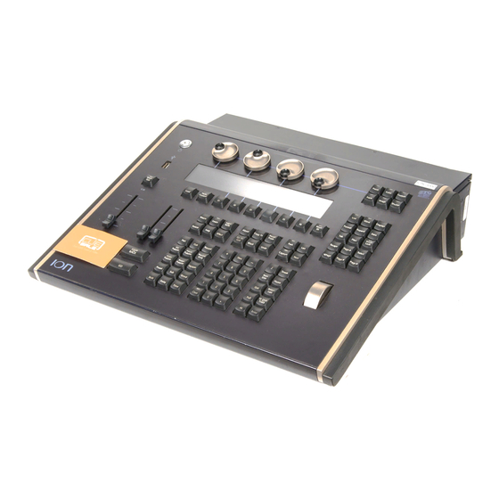
Lighting Control Console
Operations Manual
Version 1.7
C o p y r i g h t © 2 0 0 9 E le c tr o n i c T h e a t r e C o n t r o l s , I n c .
A l l R i g h t s r e s e r v e d .
P r o d u c t in f o r m a t i on a n d s p e c i f i c a t i o n s s u bj e c t t o c h a n g e .
P a r t N u m b e r : 4 3 1 0 M 1 2 1 0 - 1 . 7 . 0 R e v A
R e le a s ed : 2 0 0 9 - 0 7
Advertisement
Table of Contents

Related Manuals for ETC ION


Summary of Contents for ETC ION
-
Page 1: Lighting Control Console
Lighting Control Console Operations Manual Version 1.7 C o p y r i g h t © 2 0 0 9 E le c tr o n i c T h e a t r e C o n t r o l s , I n c . A l l R i g h t s r e s e r v e d . - Page 2 E T C , E o s , Io n , E m p h a s i s , E x p r e s s i o n , In s i g h t , I m a g i n e , F o c u s , E x p r e s s , U n i s o n , O b s e s s i o n I I , E T C N e t2 , E D M X , R e v o l u ti o n , a n d S e n s o r + , a r e e i t h e r r e g i s t e r e d t r a d em a r k s o r t r a d e m a r k s o f E l e c t r o n i c T h e a t r e C o n tr o l s , In c .
-
Page 3: Table Of Contents
Cleaning Ion........13... - Page 4 Create a New Show File........48 Open an Existing Show File .......48 Ion Operations Manual...
- Page 5 Selective Partial Show Opening ......50 Merging Show Files ........52 Printing a Show File .
- Page 6 Highlight and Lowlight ........125 Ion Operations Manual...
- Page 7 Highlight/Lowlight Rem Dim......125 Sneak ..........126 Flip .
- Page 8 Referenced Marks ........177 Ion Operations Manual...
- Page 9 Setting Referenced Mark Flags ......177 Applying Flags as Channels are Marked ....178 Reference Marks and Timing.
- Page 10 Relative Effects ........239 viii Ion Operations Manual...
- Page 11 Focus Effects ........239 Color Effects .
- Page 12 Data Sources ........283 Ion Operations Manual...
- Page 13 Ion ........
- Page 14 2 x 10 and 2 x 20 Setup ....... . 335 User Guidelines for Fader Wings ......338 Ion Operations Manual...
-
Page 15: Introduction
Introduction Welcome to the Ion Operations Manual. This manual is a comprehensive resource for users of the Ion control system. This chapter contains the following sections: • Using this Manual ........2 •... -
Page 16: Using This Manual
W A R N I N G : A Warning statement indicates situations where damage may occur, people may be harmed, or there are serious or dangerous consequences of an action. Please email comments about this manual to: TechComm@etcconnect.com Ion Operations Manual... -
Page 17: Register Your Ion
Register Your Ion Registering your Ion system with ETC ensures that you will be notified of software and library updates, as well as any product advisories. When you register, you will also be enrolled in “My ETC,” a personalized ETC Web site that provides a more direct path of communication between you and ETC. -
Page 18: Important Concepts
Important Concepts Before using Ion, you should read and familiarize yourself with the concepts defined below. You will find that understanding these terms and concepts will improve your efficiency with Ion. C h a n n e l = F i x tu r e A fixture is defined as a group of related addresses that together control a device. -
Page 19: Parameters And Parameter Categories
Ion also has a [Cue Only/Track] button that allows you to record or update a cue as an exception to the default setting. Therefore, if the console is set to Tracking, the button acts as Cue Only. -
Page 20: Move Fade
B l o c k v s . A s s e r t In previous ETC consoles, placing a block instruction on a channel was a way to treat a tracked value as a move instruction, both in editing and playback. In Ion, this behavior is now split up. -
Page 21: Live And Blind
Any new values sent to the channel will supersede any previous values, regardless of the level supplied. Ion determines the LTP value for a channel, which is overridden by any HTP input values that are higher than the LTP instruction. This is then finally modified by manual control. -
Page 22: Other Reference Materials
Other Reference Materials H e l p S y s t e m A keyhelp system is also contained within your Ion console. To access help, press and hold [Help] and press any key to see: • the name of the key •... -
Page 23: System Overview
C h a p t e r 1 System Overview Inside this chapter you will find general descriptions of your Ion control console, how it fits into a network control system, and the various areas of user interface. This chapter contains the following sections: •... -
Page 24: System Components
System Components C o n s o l e Ion is designed from conception as a fully integrated controller for conventional lights and multi-parameter devices (for example: moving lights, color scrollers, gobo wheels). Attention to detail across all areas of the system design and architecture allows you the utmost flexibility and customization of use. -
Page 25: Gateways
G a t e w a y s Ion is part of a fully networked system capable of direct output of both ETCNet2 and Net3. Gateways can be configured to listen to either ETCNet2 or Net3 and provide interface to devices in the lighting system that do not accept network communication directly. -
Page 26: Console Geography
Pow e r Button The power button on the front of the console is used to power up the Ion console. A separate power switch, located in the rear panel of the console, can be used to disconnect power from the console’s internal components. -
Page 27: Cleaning Ion
You may connect a Littlite to the side of your Ion console. C l e a n i n g I o n Should the exterior or LCD of your Ion require cleaning, you may gently wipe them with a dampened (not dripping), non-abrasive paper towel or soft cloth. -
Page 28: Console Capacities
F a d e r s • 1 dedicated Master Playback, with Go and Stop/Back • a maximum of 200 configurable playbacks, with Go and Stop/Back • a maximum of 300 configurable submasters, with Bump and Assert/Select Ion Operations Manual... -
Page 29: Outputting Dmx
Outputting DMX In order to output control levels from Ion, you can either use the DMX ports on the back of the console (see Local DMX, page 305 in the ECU appendix) or you may connect a Net3 gateway or Net2 node. - Page 30 Ion Operations Manual...
-
Page 31: System Installation
C h a p t e r 2 System Installation This chapter depicts the placement of Ion in a few lighting system risers. It also details connection of the various components of your Ion hardware. This chapter contains the following sections: •... -
Page 32: Basic System Risers
Basic System Risers DMX/RDM Net3 Gateway To ETCNet2/3 Ion Console Sensor+® Dimmers DMX/RDM Net3 Gateway To ETCNet2/3 Remote Processing Unit Ion Console Ion Operations Manual... -
Page 33: Large System Riser
Large System Riser Ethernet Net3 Remote Video Interface (RVI) Ion Console Radio Focus Two Remote Remote Radio Focus Processing Units (RFR - Receiver) Remote (RPU - for backup) Client Software (RFR - Transmitter) Contact In, Contact Out, RS232 MIDI, SMPTE... - Page 34 Ion Operations Manual...
-
Page 35: System Basics
C h a p t e r 3 System Basics This chapter explains the base level procedures for setting up, navigating, and understanding how to operate Ion. This chapter contains the following sections: • Setting Up the Hardware ......22 •... -
Page 36: Setting Up The Hardware
(CAT 5 or better) cable to the ethernet port on the back of the console. Step 5: If you plan on using the DMX ports on the back of Ion to control your lighting system, attach the appropriate DMX connector and cable to the desired port. These ports default to output DMX universes one and two. -
Page 37: Power
Press the power button, located in the top left corner of the console, above the USB port. The button LED will illuminate blue to indicate the console is running. The console will boot up into the Ion environment. The Ion system is now ready for use. N o t e : In the future, you may go straight to the welcome screen by adjusting a setting in the ECU. -
Page 38: Your First Interaction
{Let’s Begin} button visible on the screen. Use your mouse to click on {Let’s Begin} or you can press the [Enter] key. Since Ion can be set up with one or two monitors, what you will first see depends partly upon the number of monitors you are using. - Page 39 You can use the [Swap] key to change the view of the display. Multiple presses of [Swap] will yield the following responses: • First press - Expanded View - expands the top (primary) portion of the display to the full screen.
-
Page 40: Dual Monitor Configuration
In this dual configuration, Ion will first open with the live table display open on the primary monitor and the playback status and CIA visible on the other monitor. -
Page 41: The Central Information Area (Cia)
The Central Information Area (CIA) The Central Information Area (CIA) is displayed on the lower portion of the screen. By default, the CIA consists of two primary areas: the parameter display and the browser. Double arrows CIA lock Parameter display Browser CIA show/hide (shown... -
Page 42: Lock The Cia
L o c k i n g t h e F a c e p a n e l It is possible to lock out the facepanel, which prevents any actions from the command line or CIA. To lock out the facepanel, press [Clear] & [Escape]. To unlock the facepanel, press [Clear] & [Escape] again. Ion Operations Manual... -
Page 43: Using The Browser
The virtual keyboard is found with the other virtual controls in the browser. Navigate to Browser>Virtual Controls>Virtual Keyboard. This will give you click access to the Ion hardkeys on the CIA. The browser and parameter display will be hidden from view while the virtual keyboard is open. To close the virtual keyboard, press the [Displays] button. -
Page 44: Organizing The Direct Selects
Direct Selects Ion gives you the option of opening direct select modules on the monitors. To open the direct selects on a monitor: Step 1: Go to Browser>Virtual Controls>5 x 10 Direct Select Module. A window will open in the CIA displaying your monitor placement options for the module. -
Page 45: Using Direct Selects
U s i n g D i r e c t S e l e c t s Direct selects allow access to a number of controls, including a channel select display. If there are more items than can be viewed at once, you may view subsequent pages by using the page buttons ({Page }, {Page }) by the direct selects. -
Page 46: Clear Functions
From this menu you can select one of the available clear options by clicking on the desired button in the CIA. Ion will ask you for a confirmation before performing the selected clear. For {Clear Targets}, Ion will allow you to choose which record targets you want to clear. -
Page 47: Display Control And Navigation
Display Control and Navigation O p e n i n g a n d C l o s i n g D i s p l a y s Displays can be opened and closed in different ways, depending on the display. Many displays are accessible from the browser, while other displays are accessible from the LCD softkeys. -
Page 48: Swap Displays
Level Wheel to alter the display. Scrolling the wheel up zooms in. Scrolling the wheel down zooms out. Zooming the channel summary display when it is in 100 channel mode is not supported. You can also zoom using a wheel on a mouse. Ion Operations Manual... -
Page 49: Graphical User Interface (Gui) Display Conventions
Graphical User Interface (GUI) Display Conventions Ion relies on many traditional ETC indicators which you may be familiar with, as well as some new ones. This section identifies the graphical and colorful conventions used in Ion to indicate conditions to you. - Page 50 C o l o r i n d i c a t o r s Ion uses color to indicate the selection state and information about channel or parameter levels. Channel numbers/channel headers Selected Unselected • Gray number ..Unpatched channel number.
- Page 51 T e x t I n d i c a t o r s i n l i v e / b l i n d Please note examples of text indicators in the following graphic: “_” (underscore) “I” “t” “B”...
- Page 52 0. • x ....Indicates that a mark has been placed, but the mark is broken. Ion Operations Manual...
-
Page 53: [ D A T A ] K E Y
[ D a t a ] K e y Pressing and holding [Data] allows you to view the values behind any referenced or marked data. [Data] exposes the next lower reference level. So if you view a palette reference and press [Data], the absolute data will be displayed instead. -
Page 54: Using Flexichannel
{View Chans} again. At any time, you can access the last channels you defined for this state by pressing [Flexi] until this state is visible. To redefine the selected channels in the state, simply follow the steps above again. Ion Operations Manual... -
Page 55: Indicators In The Playback Status Display
I n d i c a t o r s i n t h e P l a y b a c k S t a t u s D i s p l a y If blank, default time is Indicates the timing for a used and there is no move category. - Page 56 P (see in cue 3) ..Indicates the cue will preheat. Found in the cue display “Flags” area. • R (see in cue 8) ..Indicates the source cue which refers back to an earlier mark (see Referenced Marks, page 177). Ion Operations Manual...
-
Page 57: Using [Format]
Using [Format] Some displays have multiple formats. When the display is first opened, it opens in its default view. The default view for Live/Blind is table view, with all parameter categories displayed. When the default format has been changed, those new settings will be used whenever the display is changed back to that format. - Page 58 In live, table view displays all active channel data being output from Ion. In blind, it will display all data for a single record target (cue, preset, palette) depending on what is viewed. In table view, focus, color, and beam information can be viewed in either a summary of these three categories.
- Page 59 S p r e a d s h e e t ( B l i n d O n l y ) Spreadsheet format is available only in blind mode. It is useful for viewing channel data and trends for multiple cues, submasters, palettes, or presets at one time. Cues and other record targets are displayed on the vertical axis and channel data is visible on the horizontal axis.
-
Page 60: Encoders
Ion always repaints the softkeys to coincide with your current action. To get the full use of features on your Ion system, be sure to familiarize yourself with the softkeys that become available as you program your show. -
Page 61: Managing Show Files
C h a p t e r 4 Managing Show Files This chapter explains how to create, open, and save your show files. Each of these operations are accomplished through the browser area in the CIA. This chapter contains the following sections: •... -
Page 62: Create A New Show File
• USB (E:) device - When a USB device is connected and an Ion show file (.esf) is available on the device, you will notice the USB is displayed in white text and is expandable. When the USB device is connected and no Ion show file is loaded on the device, you will notice the USB (F:) is displayed in a grey color and is not selectable. - Page 63 To reselect all show components, click the {Reset} button and all buttons will return to gray (selected). To stop the show load process, click the {Cancel} button. When you have selected or deselected all of the show components you require, click {OK}. Ion loads the selected show to the console. Managing Show Files...
-
Page 64: Selective Partial Show Opening
Target - The desired location of the components in the new show file (for ranges, this will be the location in the new show of the first component in the range, the others will follow in order). Ion Operations Manual... - Page 65 To open only partial components from a show file: Step 1: From the browser, navigate to the desired show file (see Open the desired location:, page 48). Step 2: When the partial show load screen appears, click the {Advanced} button. The partial components selection screen will appear in the CIA.
-
Page 66: Merging Show Files
USB device. To merge a show file, navigate within the Browser to: File> Merge>. Navigate to the desired storage location and press [Select]. When using merge, Ion displays only the available files. Navigate to the specific file and press [Select]. -
Page 67: Printing A Show File
Printing a Show File Ion provides you with the ability to save a show file or aspects from a show file to a PDF file for printing. Ion has three locations to save the PDF files including the Show File Archive, the File Server (if connected), or a USB device (if connected). - Page 68 The PDF will have the show name, date and time it was created, and date and times for when the show file was last saved. It also gives the Ion software version information. If multiple aspects were selected to save to the file, there will be hyperlinks at the top of the PDF so you can quickly jump to a section.
-
Page 69: Saving The Current Show File
[Update] and press [Select]. Using Save As To save an existing Ion show file to a different location or with a different name, navigate within the browser to: File> Save As> and press [Select]. Ion provides you with three locations to save an Ion show file (.esf) including the Show File Archive, the File Server (if connected) or a USB device (if connected). -
Page 70: Importing Show Files
Fixtures or Import As Custom Fixtures. Import as Library Fixtures will allow Ion to try to match the fixtures in the file with fixtures in the Ion library. Import as Custom Fixtures will bring the fixtures in as they are in the file. It is recommended to use Import as Custom Fixtures. -
Page 71: Deleting A File
Deleting a File Ion provides you with the ability to delete show files from the Show File Archive and the File Server from within the browser. To Delete a Show File Navigate within the browser to: File> Open and press [Select]. Navigate to the desired show file and press [Delete]. - Page 72 Ion Operations Manual...
-
Page 73: Chapter 5 Patch
C h a p t e r 5 Patch The Patch is where patching data is stored and can be viewed using the patch display. Once a channel is patched to an output, and the output is connected to a device (for example a dimmer, moving light, or accessory), the channel will then control that device. -
Page 74: About Patch
Patch Channels from the Encoder LCD, page When you open a new show file, Ion gives you the option of creating a 1-to-1 patch. This means that the patch will automatically have channel 1 patched to output 1, channel 2 to output 2, and so on up to the maximum channel count of your console. -
Page 75: Displays
Step 1: Press the [Displays] button. Step 2: Select the {Patch} softkey on the Ion LCD screen. The patch display will open on the primary display and the CIA will display the patch controls. Changing the Patch View By default, patch is displayed in a sequential channel view. While in the channel patch view, any numeric entry from the keypad is assumed to be a channel. -
Page 76: Address View
While in address patch view, any numeric entry from the keypad is assumed to be an output address. As it is possible to patch by either output address or port/offset, pressing the [Data] key will toggle the display to show the alternate output information. Ion Operations Manual... -
Page 77: Create And Edit Patch
Create and Edit Patch S e l e c t C h a n n e l , S e t D e v i c e T y p e , a n d O u t p u t A d d r e s s Each field identified in the patch display is also displayed in the CIA as a button. -
Page 78: Patching A Dimmer
10 to address 105, 205, and 305. When more than one device is patched to a channel, Ion automatically creates parts for each device. This is used if you need to access an address directly in the patch-by-channel display. -
Page 79: Dimmer Doubling
D i m m e r D o u b l i n g You can patch channels in Ion to accomodate for dimmer doubling with Sensor+ dimmer racks. This is done using the softkeys available in patch ({No Dim Dbl}, {A}, and {B}). -
Page 80: Patching Moving Lights
Enter a starting address for the selected channel or group of channels. • Press [At] and enter the address using the control keypad. The address may be entered in standard format ([1] [0] [2] [5]) or by using port and offset ([3] [/] [1]). Ion Operations Manual... -
Page 81: Patching A Compound Channel
(such as a fixture with a color scroller, a fixture with a gobo wheel, and so on). By default, Ion will add a part if you are trying to patch to a channel that has already been assigned an address. -
Page 82: Display Pages In Patch
{ P a t c h } D i s p l a y a n d S e t t i n g s When patch is opened, Ion defaults to this display. It provides access to data input fields that you may use to define devices in your lighting system. - Page 83 • {RDM Discovery} - If enabled, Ion will obtain RDM device information when available. The default setting is “Disabled”. RDM must be enabled in the ECU before discovery is allowed. See “Enable RDM” on page 301. When enabled, the console will automatically make discovered RDM devices available for patching.
-
Page 84: { A T T R I B U T E } D I S P L A Y A N D S E T T I N G S
• {Invert} - A moving light attribute used to invert the output of pan, tilt, or both. Select either the {Invert Tilt} or the {Invert Pan} button on the CIA. • [2] {Attributes} {Invert Pan} - inverts the output of the pan parameter. Ion Operations Manual... - Page 85 • {Swap} - A moving light attribute used to exchange pan and tilt levels. Select the {Swap} button on the CIA. • [2] {Attributes} {Swap} - swaps the pan and tilt parameters for channel 2. • {Scroller} - An attribute used to change the scroll loaded in a scroller or moving light. Select the {Scroller} button on the CIA to display the scroller picker and the scrolls available for your device.
-
Page 86: { D A T A B A S E } D I S P L A Y A N D S E T T I N G S
• [1] [Thru] [2] [0] {Offset} [2] {Type} {VL1000} [At] [1] {Offset} [2] [0] [Enter]- selects every other channel in the list and patches them with an offset of 20 addresses. Ion Operations Manual... -
Page 87: Patch Channels From The Encoder Lcd
Patch Channels from the Encoder LCD You may use the encoders and LCD to patch channels in Ion. This is an alternative to using the methods described above. The end result will be the same, this simply gives you the ability to patch without requiring the use of the mouse or external touchscreen. -
Page 88: Using The Scroller/Wheel Picker And Editor
{Color Wheel} or {Gobo Wheel}). The picker displayed is specific to the selected attribute (the scroll picker will display when {Scroller} is clicked, the color wheel picker will display when {Color Wheel} is clicked, and so on). Select the scroll or wheel type. Ion Operations Manual... -
Page 89: Using The Editor
In the above image, {ETC Scroll} is the default scroll for the selected ETC Source Four Revolution. The list of gel colors as they are installed in the scroll are displayed to the left with a color chip for easy reference. - Page 90 (using the {New} frame button) or you can click in the next frame area to add more frames. N o t e : An {Invert} softkey will display when creating or copying a wheel or scroller. {Invert} is used to reverse the order of frames. Ion Operations Manual...
- Page 91 E d i t i n g a c o p y o f a s c r o l l o r w h e e l If a copy has been made of an existing scroll or wheel, the copied scroll or wheel will display as {New Wheel x} before the standard manufacturer offerings.
-
Page 92: Calibrating A Scroller
Step 10: Repeat steps 6-9 until you have calibrated all of the frames. Step 11: Press [Live] or [Blind] to close the virtual encoder display. You can also calibrate from the encoder LCD. This eliminates the need for the virtual encoder display. Ion Operations Manual... - Page 93 To calibrate from the LCD: Step 1: Select the channel of the scroller you wish to calibrate. Step 2: Press the [Color] encoder button to the upper right of the LCD. Multiple presses may be required before the scroller encoder is visible in the virtual encoder display. Step 3: Use the encoder to move all the way to the last frame of the scroller.
-
Page 94: Keywords
Keywords Query is a feature available in Eos, but not in Ion. Since show files are compatable between the two consoles, in Ion you can assign keywords to channels that can be queried when the show file is loaded onto an Eos. -
Page 95: Fixture Creator
Fixture Creator Ion provides you with the ability to create your own fixture type within patch and store it with your show file. You can name the fixture, assign all necessary parameters, define the address and operational range of those parameters, and set lamp controls. -
Page 96: Creating A New Fixture
Press [Enter]. The name will appear in the “Type” column for the new fixture. A d d p a r a m e t e r s After naming the fixture, you can specify which parameters the new fixture contains. Ion Operations Manual... - Page 97 To add parameters to a new fixture: Step 1: Use the [Page] keys to select the new fixture from the fixture list. Step 2: Click {Edit}. That fixture will open in a new display in the CIA. Step 3: Determine the total number of parameters that your fixture has. Do not count 16-bit channels as two channels, this will be done in a later step.
- Page 98 C A U T I O N : Be careful not to duplicate any address in the DMX order of parameters in the new fixture. Ion does not prevent you from duplicating addresses. To define the LDMX address of any 16-bit channel: LDMX or “low-DMX”...
-
Page 99: Copying A Fixture
U p d a t e L i b r a r y When a new library is installed on Ion (for example, included in a software update), changes in library data will not automatically update your show files. This is to prevent library changes from affecting a functional show file. - Page 100 Ion Operations Manual...
-
Page 101: Using Groups
C h a p t e r 6 Using Groups Groups are channel selection devices used for fast recall of specific channels. A maximum of 1000 groups can be recorded. Once recorded, they are accessible from the keypad, direct selects, and through the displays. -
Page 102: Recording Groups Live
[1] [0] [Thru] [2] [Record] [Group] [1] [Enter This will record channels 10 through 2 to Group 1, and then if you select the group you can cycle through the channels using [Next] starting with 10, then 9, then 8, and so on. Ion Operations Manual... -
Page 103: Offset
O f f s e t You can use the {Offset} softkey to aid in channel selection prior to storing groups. The offset options are {Odd}, {Even}, {Reverse}, and {Random}. For example: • [1] [Thru] [9] {Offset} {Odd} [Record] [Group] [5] - records all odd numbered channels between 1 and 9 to Group 5. -
Page 104: Group List
• [2] [Delete] [Enter] - removes channel 2 from, the group. • {Random} [Enter] - rearranges the channels in the group randomly. • {Reverse} [Enter] - reverses the order of the channels within the group. Ion Operations Manual... -
Page 105: Using Groups As A Channel Collector
U s i n g G r o u p s a s a C h a n n e l C o l l e c t o r [Group] can be used as a quick way to collect channels from submasters, cues, palettes, or presets. - Page 106 Ion Operations Manual...
-
Page 107: Setup
C h a p t e r 7 Setup This chapter describes the processes involved in changing your system settings to meet your preferences. It also covers advanced setup functions. This chapter contains the following sections: • Opening Setup ........94 •... -
Page 108: Opening Setup
The CIA will repaint to display the setup screen and the softkeys will change to display the various subcategories of setup. Ion defaults to display show settings, however if you have changed the view to another subcategory, Ion will remember the view you were in when you return to setup. The setup subcategory softkeys are: •... - Page 109 {Num of Channels} You may use this field to set the number of channels in your Ion to the number of channels in your system. Ion supports a maximum of 10,000 channels. Enter the number of channels for your system using the keypad.
- Page 110 To change the mapped location of any playback, click the {Mapped to} button for that slider and enter the number you wish to assign to it. Unmapped - Selecting unmapped for any fader leaves that fader open and unoccupied. Ion Operations Manual...
- Page 111 Grandmasters, submasters, and playbacks may appear on more than one fader page. In a partitioned control environment, the mapping of the faders (with the exception of the master fader) is global. N o t e : Specifying a {Mapped to} location does not specify the cue list that will be loaded to that playback.
- Page 112 Also known as "Device ID" this setting allows you to establish the MIDI Show Control device ID for Ion. The device ID can be set from 0-126. Ion will process commands sent to the matching Device Id. Ion will also process commands sent to Device Id 127 (All Call). For example: •...
- Page 113 “Disabled”. The default is “Enabled”. {Serial Group Ids} This touchbutton is for setting up which serial group IDs the Ion will listen to. Serial Group IDs are from 1-32. Ion can be set to listen to multiple group IDs. • {Serial Group Ids} [1] [+] [5] [Enter] P a r t i t i o n s Pressing the {Partitions} button in Show setup opens the partition display in the CIA.
-
Page 114: Desk
This setup softkey accesses settings for the user identified on the associated Ion device. Changing these settings does not impact other Ion controllers on the network assigned a different user ID. { R e c o r d D e f a u l t s } This screen enables you to change general record defaults as well as change the default parameter category times associated with certain actions ([Back], [Go to Cue], and [Assert]). - Page 115 Any value between 0-100 may be entered. The default is 100. Plus% - This sets the level for the +% (which is accessed in Ion by pressing [At] [+][+]), which will increase the selected channel by the set percentage. Any value between 0-100 may be entered.
- Page 116 { F a c e P a n e l } Sounds You can adjust the frequency and length of the audible sounds that Ion delivers. Sounds are qualified as being either an error sound or an advisory sound. Both types of sounds can be adjusted from this setup screen in the CIA.
- Page 117 { D i s p l a y s } This desk setting button gives you access to the Ion display settings. High Contrast Display This button toggles the setting between “Enabled” and “Disabled”. When enabled, high-contrast brightens the cue numbers and channel numbers in displays and also brightens the magenta used to show tracked values.
- Page 118 This screen allows you to select the orientation and paper type for PDF files. { L C D S e t t i n g s } This screen allows you to adjust the brightness and contrast settings for the Ion LCD and the fader wing LCDs.
-
Page 119: Security
Clicking {Identify} will display numbers on each wing’s display to aid in configuration. The numbers do not identify the wings as to their actual order. Order is determined from left to right. The left most wing will contain the first faders, unless a 1x20 wing is attached. A 1x20 will always contain the first faders regardless of other wings to the left of it. - Page 120 Ion Operations Manual...
-
Page 121: Basic Manual Control
C h a p t e r 8 Basic Manual Control Ion provides a variety of ways to select and command control channels. This chapter identifies the many basic ways you can select channels and manipulate show data within Ion. -
Page 122: Selecting Channels
Channels are deselected when any action is taken on the keypad that is unrelated to manual control, such as recording groups and cues, or updating a record target, etc. You can also press [Clear] after a terminated command line to clear the channel selection. -
Page 123: Offset
[ N e x t ] a n d [ L a s t ] The [Next] and [Last] buttons increment and decrement channel selection. If only one channel is selected, [Next] increments the channel selection to the next sequential channel, while [Last] decrements the channel selection by one. -
Page 124: Setting Intensity
L e v e l W h e e l You may set intensity for selected channels or addresses using the level wheel. Rolling the level wheel upwards increases intensity. Rolling it downwards (towards you) decreases it. Ion Operations Manual... -
Page 125: Manual Control Of Non-Intensity Parameters (Nps)
Manual Control of Non-intensity Parameters (NPs) Non-intensity parameters can be set with a variety of controls including the control keypad, buttons on the central information area (CIA) and the encoders. P a r a m e t e r D i s p l a y The parameter display in the CIA is populated with only those parameters that are found in the patched devices. -
Page 126: Setting Parameters With The Keypad
• Form- includes parameters that affect the quality or size of the light output, such as edge, zoom, iris, IMF, frost, etc. • Image - includes anything that drops into the gate, such as gobos, effects wheels, etc. • Shutter - includes all of the framing devices for the luminaire. - Page 127 E n c o d e r L C D s c r e e n The encoder LCD displays the active parameter category loaded on the encoders, as selected by the page buttons. Each encoder has an associated control section in the LCD that provides visual indication of: •...
- Page 128 • [1] {Color} [Home] [Enter] - homes all of the color data for channel 1. You may also use the [Color] encoder page button for this command. Ion Operations Manual...
- Page 129 If there are multiple instances of a device in a single channel (such as two fixed gobo wheels or two color wheels, etc.), each device will load onto separate encoders.
- Page 130 • Edge - controls the hard and soft qualities of a spot luminaire. While some fixtures may call this parameter “focus”, it is always represented as “edge” in Ion, to avoid confusion with “Focus” which refers to pan and tilt data. The edge encoder provides two buttons, [Hard] and [Soft], which set the selected luminaire to its hardest (sharpest) edge or its softest edge.
- Page 131 Color scroller data will display on the encoders and displays as frame numbers, F1, which would be frame 1, F2 for frame 2, etc. F1.5 is halfway between 1 and 2. F2+ will display if the frame is less than 2.5 and F2- if the frame is greater than 1.5.
-
Page 132: Using The Color Picker
Hue is the actual color. It is measured in angular degrees around the cone starting and ending at red = 0 or 360 (so yellow = 60, green = 120, etc.). Saturation is the purity of the color, measured in percent from the center of the cone (0) to the surface (100). -
Page 133: Home
Home Ion is equipped with a [Home] hardkey. This hardkey allows you to home a specific parameter. Additionally, you may home all of a channel’s non-intensity parameters or home only a specific category (I, F, C, B). Homing a channel, category, parameter, or submasters will return it to the default value. -
Page 134: Multiple Intensity Channels
Multiple Intensity Channels When a multiple intensity channel is patched, Ion assigns it a master intensity. The master intensity can be used to control the multiple intensities together. The master intensity is handled in the same way as the intensity of a single intensity channel. Levels can be set via the level wheel, from the keypad, and the encoders. -
Page 135: Lamp Controls
Lamp Controls Lamp controls allow you to execute control functions of selected fixtures such as calibrate, douse lamp, strike lamp, and reset. Each fixture type has its own set of lamp control options which are available to you when you select the fixture from live and press the {Lamp Cntrls} softkey. This information is also available using [About] (see Using About, page 245). -
Page 136: Using +% And
Using +% and -% Use +% and -% to incrementally change parameter values. To access this function on Ion, press [At] [+][+] or [At] [-][-]. By default, +% and -% are assigned a value of 10. This can be changed in Setup. -
Page 137: Remainder Dim
Remainder Dim [Rem Dim] temporarily provides a zero intensity to all channels except those that are currently selected, those that are parked, or those with intensity contributions from submasters. If the remainder dim command is reversed, the stage returns to its previous state. You may use the following commands for remainder dim: •... - Page 138 Without the [Rem Dim] command, the submaster would still contain channels 1 through 10 at full. A [Rem Dim] command can also be used on a selective cue record. It will force any channels not included in the record, but are tracking forward from a previous cue, to zero. Ion Operations Manual...
-
Page 139: Highlight And Lowlight
Highlight and Lowlight Ion can be placed in Highlight or Lowlight mode. Channels selected while in these modes will either go to a default setting, or to a value provided by a highlight/lowlight preset (established in setup). Modifications can then be made to those channels. Any changes will be maintained when the highlight/lowlight mode is removed. -
Page 140: Sneak
{Flip} is a softkey in the encoder LCD. To access it, press and hold either the “Pan” or “Tilt” encoder, then press the corresponding softkey. The following example illustrates the use of {Flip}: • [channel list] {Flip} Ion Operations Manual... -
Page 141: Channel Check
Channel Check Channel check allows you to quickly step through all of your patched channels. This is useful for checking lamps or checking focus. N o t e : Parked dimmers will not be affected by the channel check feature. The following examples illustrates the how to use the channel check feature: •... -
Page 142: Flash
When a {Move To} command is given, data is removed from its current location and moved to its new location. If the new location already contains data, a confirmation is required by Ion (unless disabled in Setup). Existing data in the new location will be completely overwritten if a {Move To} command is confirmed. -
Page 143: Storing And Using Presets
Up to 1000 presets may be stored in Ion using decimals or whole numbers and they can contain absolute data or a mix of IFCB palettes. Presets can not refer to other presets. -
Page 144: Storing Presets Live
You may also use the filters and {Make Null} as additional tools to decide what data will be stored. For more information on these features see Using Filters. When you rerecord an existing Preset, a confirmation will be required, unless confirmations have been disabled in Setup. Ion Operations Manual... -
Page 145: Storing Presets Using [Record Only]
S t o r i n g P r e s e t s u s i n g [ R e c o r d O n l y ] [Record Only] is a selective record process that stores only manual parameter data. Therefore, when used to record presets, only manual data for channels will be stored in the preset. -
Page 146: Recalling Presets
When a preset is recalled, parameter changes will follow the manual timing defaults, if enabled. Any preset which is contributing to live output from Ion is considered to be “active.” You may recall presets using any of the following methods: •... -
Page 147: Editing Presets Live
Editing Presets Live There are two ways to edit a preset in Live. You may rerecord the preset or you may use [Update]. R e r e c o r d Rerecording follows the conventions of [Record] and [Record Only]. The only exception is that a confirmation is required to actually rerecord the preset. -
Page 148: Using The Preset List
• <Preset> [2] [Copy To] [9] [Enter] [Enter] - copies the contents of preset 2 to preset 9. Preset 2 will remain in the list. The second [Enter] is not required if you have disabled confirmations in setup. You can also use [Copy To] from palettes to presets. Ion Operations Manual... -
Page 149: Editing Presets In Blind
Editing Presets in Blind All presets can be viewed and edited in blind. To open a preset in blind, you can do any of the following: • Press [Blind] & [Preset] • Press [Blind] & {Preset x} - opens to the specific preset •... -
Page 150: Editing In Spreadsheet View
• [Preset] [1] [thru] [5] {Move To} <Preset> [9] <thru> [Enter] - this will move presets 1-5 to presets 9-14 respectively. You do not have to supply the end value for Ion to perform the move. If presets 9-14 already exist you will be asked to confirm this move. -
Page 151: C H A P T E R 1 0
C h a p t e r 1 0 Storing and Using Palettes Palettes are building blocks that can be used to create presets, cues and effects. Palettes are a critical component when using moving lights and can save considerable programming time when editing show data. -
Page 152: About Palettes
Intensity, Focus, Color, and Beam. Ion supports up to 1,000 palettes of each of the four types. Palettes can be recorded as decimal or whole numbers and are automatically filtered into IFCB categories. Color data cannot be placed in beam palettes, intensity cannot be included in focus palettes, and so forth. -
Page 153: Storing Palettes Live
[Record], [Record Only], and using filters are the most common ways. When [Record] is used, Ion will store the relevant parameter category data (intensity, focus, color or beam) for all channels that are not currently at their default value. -
Page 154: Storing Palettes With [Record Only]
• [1] [Thru] [9] {Iris} {Zoom} [Record Only] [Beam Palette] [5] [Enter] - stores only manual zoom and iris data for channels 1-9 to beam palette 5. Ion Operations Manual... -
Page 155: Using Filters With Palettes
U s i n g F i l t e r s w i t h P a l e t t e s Filters can be used to modify what data is stored to a palette by a record action. The parameters that are active or filtered allow those parameters to be stored to record targets. -
Page 156: Recalling Palettes
When recalling palettes, only channels that are selected at the point of recall will be affected by the palette recall. The data recalled from a palette is referenced. To break the reference you may use {Make Absolute}. Ion Operations Manual... -
Page 157: Editing Palettes Live
Editing Palettes Live N o t e : If a palette is already recorded, [Record] replaces all existing data. [Record Only] is a selective store, therefore it adds data. Recording over a previously existing palette requires a confirmation, if confirmations are enabled in the setup menu. It is also possible to [Update] to add manual changes to the record target. -
Page 158: Editing Palettes In Blind
[Recall From], [Copy To], {Replace With}, and {Move To} may be used to create and edit palette data. See Advanced Manual Control, page 195. N o t e : While editing palettes in blind, hitting [Recall From][Recall From] will put [Recall From][Palette] on the command line. Ion Operations Manual... -
Page 159: Editing Palettes In Spreadsheet View
• [palette type] [1] [thru] [5] {Move To} <palette type> [9] <thru> [Enter] - this will move palettes 1-5 to palettes 9-14 respectively. You do not have to supply the end value for Ion to perform the move. -
Page 160: Editing Palettes In List View
• [1] [5] {Edit} [Enter] - selects palette number 15 and brings the blind display into focus, with palette 15 selected for editing. You can use the [Next] and [Last] buttons to access the other palettes, or select a new palette for editing from the keypad. Ion Operations Manual... -
Page 161: Deleting Palettes
D e l e t i n g P a l e t t e s To delete color palette 1, press [Delete] [Color Palette] [1] [Enter] [Enter]. When palettes are deleted, any references in cues will be converted to absolute data. R e m o v i n g C h a n n e l s f r o m a P a l e t t e You can remove specific channels from a palette. - Page 162 Ion Operations Manual...
-
Page 163: C H A P T E R 1 1
When cues are created they are stored in a cue list. By default, recording cues will result in a single cue list, identified as cue list 1. While other cue lists can be recorded in Ion, this chapter deals primarily with working in a single cue list. For more information on multiple cue lists, see... -
Page 164: Basic Cueing
(such as preheat, follow or hang instructions, and so on). In Setup, you have determined if Ion will operate in a Cue Only or Tracking mode. By default, the system is set to tracking, therefore this section of the manual primarily addresses working in tracking mode. -
Page 165: Recording Cues In Live
Ion is a tracking console, meaning once something is recorded into the cue list, the cue list will always contain information about that channel or parameter unless it is nulled, using the {Make Null} command, or filtered using the parameter filters. -
Page 166: Using Record Only
• [selected channels] {Color} [Record Only] <Cue> [4] [Enter] - stores only the color data for the selected channels into cue 4. As with [Record], filters can further restrict stored data if deployed when using [Record Only]. “Using Filters” on page 183. Ion Operations Manual... -
Page 167: Using Selective Store
U s i n g S e l e c t i v e S t o r e You may use the [-] button to withhold information from a cue or use the [+] button to specify a particular channel or parameter to be included in the record action. These actions are both selective stores. -
Page 168: Using [Cue Only / Track]
5. The data will track forward in the list until the next move instruction or block. • [Record Only] <Cue> [2] [thru] [7] [Track] [Enter] - stores all manual data. The stored data will track from cue 2 and stop at cue 7. Ion Operations Manual... -
Page 169: Timing
S e t t i n g C u e L e v e l T i m i n g Unless you specify otherwise, Ion assigns default fade times to any cue you record. Default timing is designated in Setup. Cue level timing can be applied when a cue is recorded or can be added or modified later. -
Page 170: Non-Intensity Parameter Category Timing
• [Cue] [2] {Color} [Time] [5] [Enter] - Redefines color time to 5 seconds. • [Cue] [3] {Focus} [Time] [-] [2] [Enter] - Removes 2 seconds from the current time. • [Cue] [7] {Beam} [Time] [+] [3] [Enter] - Adds 3 seconds to the current time. Ion Operations Manual... -
Page 171: Delay Time
D e l a y T i m e Delay is used to stage the execution of parameter categories within a cue or cue part. The countdown of a delay time begins the moment the cue is executed (for example, pressing [Go]). Delay times can be added to any cue or to any specific parameter category within the cue, which will postpone the parameter transition until the delay time has elapsed. -
Page 172: Discrete Channel Or Parameter Timing
The [Time] key can be held down to see the discrete delay or time information for channels in Live/Blind. Delay is displayed first, followed by the timing value. Ion Operations Manual... -
Page 173: Assigning Cue Attributes
A s s i g n i n g C u e A t t r i b u t e s You can record cues with specific attributes to affect how cues behave when executed. Cue attributes include follow time, hang time, link, loop, curve, rate and label. Cue attributes can be entered when the cue is initially recorded, or they can be added or modified at a later date. - Page 174 4 times (once plus 3 loops) and then stop in cue 2. The loop value specifies the number of times the loop instruction will be performed. Since the sequence has run once prior to the loop command, the total number of passes will be the specified number of loops +1. Ion Operations Manual...
-
Page 175: Clearing Cue Attributes
Rate The {Rate} softkey can be used to apply a rate adjustment to all timing in the cue. The default rate is 100%, which is real time. To slow a cue down, set the rate below 100%, to speed the cue up, set the rate above 100%. -
Page 176: Flags
Ion also supports an “auto-block” function. Auto-block can protect your cue data from unwanted changes. For example, in cue 5 you set channel 1 to 50%. It is stored as a move instruction. Then, you later go back to an earlier cue and set channel 1 to 50% and it tracks forward to cue 5. -
Page 177: Assert
A s s e r t Assert is a way to make a tracked or blocked value act as a move instruction on playback. It is often used in a multiple cue list environments, or to assure that a transition happens in the desired time Using Assert, page 189 for more information on asserts in multiple cue lists. -
Page 178: Using The Execute List
R e m o v i n g a t r i g g e r : To remove a trigger, access the cue number and press {Execute}, the record target type and press [Enter]. • [Cue] [5] {Execute} {Cue/Macro} [Enter] Ion Operations Manual... -
Page 179: Modifying Cues Live
Modifying Cues Live Recorded cues can be modified live. Cue attributes (such as link, loop, label and so on) may be edited as well. The cue does not need to be active (played back) to change cue attributes. You may also change cue attributes for a range of cues if you wish. -
Page 180: Using Record Only
• [Cue] [4] <More SK> {Move To} <Cue> [8] [Enter] - moves the contents of cue 4 to cue 8. Cue 4 is removed entirely. If cue 8 already existed, a confirmation will be required before replacing cue 8 (unless confirmations have been disabled in setup). Any contents of cue 8 will be replaced entirely. Ion Operations Manual... -
Page 181: [Update]
When you press [Update], a dialogue box will open in the CIA and the following options are displayed: • {Update All} - updates the background cue and all references (nested and otherwise). Ion defaults to this option. • {Make Absolute} - updates the background cue and convert all levels to absolute values, thereby removing any references. - Page 182 “R” in superscript next to the channel’s intensity. By default, Ion updates any referenced data that was included in the cue. For Example: Cue 5 is recalled Live. It contains references to color palette 1 and preset 2. You make changes to channels included in these record targets.
- Page 183 U s i n g C u e O n l y / T r a c k The [Cue Only/Track] key can be used as an applied exception to the cue only/track system setting. Therefore if the system is set to Cue Only, the key behaves as a [Track] command. Alternatively, if the system is set to Track, the key behaves as a [Cue Only] button.
- Page 184 In these situations, if the updated cue is not the source of a channel’s live value, manual data will remain manual. If the updated cue is the source of the current value, the values will change to magenta (indicating tracked) when the update is completed. Ion Operations Manual...
-
Page 185: Recording And Editing Cues From Blind
Recording and Editing Cues from Blind Press [Blind] and the selected cue will be displayed. You can make changes to cues in the blind display using either the summary, table, or spreadsheet views. N o t e : Edits in blind take effect immediately. [Record] or [Update] commands are not required in blind. -
Page 186: From Summary Or Table Views
Editing cue ranges is possible in spreadsheet view. {Move To} is only available from this view. To select an entire cue range, you can press [Cue] [enter the first cue] [Thru] [Enter]. Ion Operations Manual... -
Page 187: Using Encoders In Blind
R e p l a c e W i t h {Replace With} is used to select channels that have certain specified values and then provide new instructions for those values. For Example: Select a range of cues: • [Cue] [1] [Thru] [9] [Enter] Select a range of channels that are used throughout these cues and enter a change instruction: •... -
Page 188: Deleting Cues
1 are unaffected. • [Delete] <Cue> [2] [thru] [8] [Cue Only/Track] [Enter] [Enter] - deletes cues 2-8, making exception to the default setting, as described above. Ion Operations Manual... -
Page 189: C H A P T E R 1 2
This allows your moving lights to unobtrusively perform non-intensity parameter transitions in an inactive (darkened) state. Ion provides two different methods to mark lights: AutoMark and Referenced Marks. This chapter contains the following sections: •... -
Page 190: Automark
An AutoMark will happen in the time of the cue in which is moving (the “M” cue), unless the channel has discrete timing. In which case, the discrete timing will apply to the moves. Discrete timing is applied in the cue where the move instruction is stored. Ion Operations Manual... -
Page 191: Referenced Marks
This is also the cue where the non-intensity moves are stored. In order to use mark properly, you must specify channels to be marked in the source cue. Ion will not assume all moving lights apply to any given mark. -
Page 192: Applying Flags As Channels Are Marked
• [Cue] [n] {Mark} [Enter] To remove a mark from a channel: • [select channel] {Mark} [Enter] N o t e : If a mark is removed from a channel in live, the corresponding cue must be updated. Ion Operations Manual... - Page 193 It is also possible to mark to a cue that doesn't exist, and when the mark is stored, Ion will automatically create the cue to mark to. For Example: If cue 2 does not exist yet: • [select channels] {Mark} [2] [Enter] The command line will display, “Create Mark Cue?”...
- Page 194 ....Indicates that a mark has been placed, but the mark has been broken. If possible, Ion will automark the lights. Ion Operations Manual...
-
Page 195: Reference Marks And Timing
R e f e r e n c e M a r k s a n d T i m i n g Movement of non-intensity parameters in conjunction with a mark will adhere to the following timing rules. If discrete timing is used for non-intensity parameters: When channels execute a mark, the moves will use the discrete time(s) assigned to them in the source cue. - Page 196 Ion Operations Manual...
-
Page 197: C H A P T E R 1 3
C h a p t e r 1 3 Using Filters Filters are used to determine which parameters can be stored to cues, palettes, and presets. The filter selection tool in the CIA affects record operations as long as the filters are set. This chapter contains the following sections: •... -
Page 198: Record Filters
The parameter category buttons can be used to select filters, as follows: • Intensity (enables recording intensity data) • Focus (enables recording pan and tilt) • Color (enables recording color data) • Beam (enables recording all beam data) Ion Operations Manual... -
Page 199: Partial Filters
To apply record filters by category: Step 1: Click {Filters} in the top-right corner of the parameter grid in the CIA. The parameter buttons change to display filter selection. Step 2: Click the parameter category button {Intensity/Focus/Color/Beam} for the category you want to include in the record target. -
Page 200: Storing Data With Record Filters
• Cues - Active filter settings impact what is stored in cues, even when using “record only” commands. • [Update] - Filter settings are ignored. • [Recall From] - Recall from instructions are not affected by the filters. Ion Operations Manual... -
Page 201: C H A P T E R 1 4
C h a p t e r 1 4 Working with Multiple Cue Lists Ion provides many useful tools to allow you work efficiently and simultaneously with multiple cue lists. This chapter focuses on the features and methods used when working with more than one cue list. -
Page 202: Recording To A New Cue List
You may record up to 999 cue lists in an Ion show file. The cue list that you are storing to is always determined by the selected cue, unless you specify a different cue list. -
Page 203: Using Assert
U s i n g A s s e r t By default, channel parameters only respond to move instructions during playback (see Cue List Ownership, page 6). The [Assert] function allows tracked or blocked data from a cue to be replayed, even when another cue list has taken control of that channel or parameter. -
Page 204: Using Allfade
• Recalling another cue list in the command line - [Cue] [3] [/] [Enter] • Recording a cue to another cue list - [Record] <Cue> [3] [/] [8] [Enter] • Playing back a cue from the fader of another cue list - press [Go] for the associated fader. Ion Operations Manual... -
Page 205: Using [Go To Cue] With Multiple Cue Lists
• [Go To Cue] [2] [/] [0] [Enter] N o t e : Ion has an added intensity parameter for LED fixtures, that by manufacturer default, have only RGB parameters but no intensity parameter. With this added control, the LED fixture will respond to the [Go To Cue] [0] command. -
Page 206: Using The Cue List Index
(bottom) to increase or decrease the viewing area of either section. Hover the mouse arrow over the list boundary until it changes to the familiar “move boundary” icon. Then click and drag the boundary up or down to the desired height. Ion Operations Manual... - Page 207 HTP instruction is higher than the LTP value. When a cue from an HTP cue list is executed, Ion determines if the intensity value when the cue is complete will be higher than the current setting. If so, the intensity will begin to fade from its current value to the required value in the incoming cue using the cue's upfade time.
- Page 208 You can edit any of the cue attributes for the cue selected in the index, but the cue contents must be edited in the blind display. See “Recording and Editing Cues from Blind” on page 171. Ion Operations Manual...
-
Page 209: C H A P T E R 1 5
C h a p t e r 1 5 Advanced Manual Control This chapter describes some more advanced features for manual control functions. These features can save you valuable programming time. This chapter contains the following sections: • Using [Copy To] . -
Page 210: Using [Copy To]
• [Cue] [1] [/] [1] [thru] [1] [0] [Copy To] [Cue] [5] [/] [5] <thru> [Enter] - copies cues 1 thru 10 from cue list 1 to cue list 5, starting with cue 5. • [1] [Copy To] [2] [0] {Only Levels} [Enter] - copies only the parameter information from channel 1 to channel 20. Ion Operations Manual... -
Page 211: Using [Recall From]
Using [Recall From] [Recall From] is similar to [Copy To], except that it retrieves data from other locations, and can be used only for a channel list recalling from the same channel list but in a different location (for example, a cue). [Recall From] is essentially a “copy from” command. All parameter data for selected channels will be recalled, or by using the IFCB category buttons or parameter buttons, you may recall subsets of channel data. -
Page 212: Using {Make Null
{Make Null} both restricts the recorded data from playing back and prevents other values from tracking in. Therefore, if the cue were executed as an out-of-sequence cue or asserted, no data would play back or track in for any nulled values. Ion Operations Manual... -
Page 213: Using {Make Manual
Using {Make Manual} The {Make Manual} softkey can be used to convert cue or submaster data into manual values, allowing it to be included in [Record], [Record Only], and [Update] operations. • [5] {Make Manual} [Enter] - selects channel 5 and makes all of its current parameter settings manual data. -
Page 214: Using [Capture]
It is also possible to “latch” capture on. This will automatically capture all manual changes as they are made. Pressing [Capture] [Capture] [Enter] automatically captures subsequent manual changes. The command line will read “Capture Enable * and the Capture LED will illuminate. To remove the capture latch, press [Capture] [Capture] [Enter] again. Ion Operations Manual... -
Page 215: Using [Undo]
Using [Undo] Undo is a method to reverse or “undo” certain operations performed in the software.You can use [Undo] to reverse any command that results in a change to data that would be saved to the show file or any command that changes manual levels in live. Commands that can be reversed using [Undo] are: •... - Page 216 Ion Operations Manual...
-
Page 217: C H A P T E R 1 6
C h a p t e r 1 6 Multipart Cues Cues can be divided into up to 20 parts. This chapter describes the methods used to create and edit multipart cues. This chapter contains the following sections: • Record a Multipart Cue in Live . -
Page 218: About Multipart Cues
Part 1 of any multipart cue is where all unassigned move instructions will reside. Therefore, if the body of the cue (which is the normal behavior) is to be in part 1, you can simply select the channel or parameter list that you wish to place in parts 2 and higher. Ion Operations Manual... -
Page 219: Setting Multipart Cue Attributes
S e t t i n g M u l t i p a r t C u e A t t r i b u t e s Cue attributes, such as [Time], [Delay], [Block], [Assert], [Label], [Rate], [Mark], and {AutoMark Off} can be assigned in part cues. -
Page 220: Using Update In Live
When cue 2 is active, select channels 1 through 5 and set new levels for the color scrollers. Update only part 4 of the multipart cue 2 with the new scroller levels. • [1] [Thru] [5] [Scroller] [Update] [Part] [4] [Enter] Ion Operations Manual... -
Page 221: Storing A Multipart Cue In Blind
Storing a Multipart Cue in Blind N o t e : Edits in blind take effect immediately, they do not require a [Record] or [Update] command. C h a n g i n g a S i n g l e P a r t C u e t o a M u l t i p a r t C u e When working in blind, more often than not you will be breaking a single part cue into a multipart cue. - Page 222 Ion Operations Manual...
-
Page 223: C H A P T E R 1 7
C h a p t e r 1 7 Cue Playback Ion has many features that aid in cue playback. The playback section is located on the left side of the console and includes the master fader pair, grandmaster, load button, and the fader control button. -
Page 224: Introduction To Playback
P l a y b a c k C o n t r o l s Fader control button Load button Master fader pair Ion Operations Manual... -
Page 225: Selected Cue
Selected Cue The selected cue is always indicated just above the CIA. The selected cue and all of its attributes are displayed near the bottom of the live/blind display and on the playback status display. L i v e / B l i n d When working in live, the selected cue is always the last cue you recorded, edited, updated or played back. -
Page 226: Out-Of-Sequence Cues
However, if she presses [Go to Cue] [5] [Enter] (an out-of-sequence execution), even though the value for channel 1 in Cue 5 is a tracked value, channel 1 will fade from the manual value of 50%, to full in the Go-to-cue time. Ion Operations Manual... -
Page 227: Go To Cue
G o T o C u e [Go to Cue] instructions can be executed from any operating mode. By default, a [Go to Cue] instruction is an out-of-sequence cue and will follow the rules of such (see Out-of-Sequence Cues above. Following are examples of [Go To Cue]: •... -
Page 228: Slider Module
C h a n g i n g F a d e r P a g e s Ion has 30 pages of ten faders each. When using virtual faders, you can page through the 30 available pages of faders by clicking the desired page in the virtual fader display. Click the arrow buttons to advance through the page number buttons until you find the desired page. -
Page 229: Playback Fader Controls
Playback Fader Controls In Ion, many of the buttons mentioned below exist as softkeys. In order to have access to some of these keys, press [Fader Control]. The softkeys will change to display the fader control keys. You may press [More SK] if the green LED is illuminated, to view additional fader control buttons. - Page 230 Manual timing can also be set at a cue level: • [Record] [Cue] [5] [Time] {Manual} [Enter] Manual timing can also be set at a cue category level: • [Record] [Cue] [6] [Color] [Time] {Manual} [Enter] Ion Operations Manual...
- Page 231 M a n u a l I n t e n s i t y O v e r r i d e An intensity transition may be taken over manually and the transition captured by dropping the fader down until it reaches the percentage of cue completion (i.e. if the cue is 50% complete, when the fader is manually dropped to 50%, the intensity transitions will be captured and the intensity portion of the cue completed by moving the fader manually between 50% and full or anywhere in between).
-
Page 232: Using Assert (Playback Button)
• [Effect] [6] [thru] [9] [Fader Controls] {Freeze} [Enter] - to freeze a specified range of effects. When an effect is in freeze mode, you can use the same command to unfreeze: • [Effect] [2] [Fader Controls] {Freeze} [Enter] • [Effect] [6] [thru] [9] [Fader Controls] {Freeze} [Enter] Ion Operations Manual... -
Page 233: Using Stop Effect
U s i n g S t o p E f f e c t The {Stop Effect} softkey can be used to stop all effects from operating on any or all faders, or it may be used with the control keypad to stop a specific effect. •... -
Page 234: Using Rate Override
If a cue is complete, any rate adjustment applied affects the cue in the pending file. When that cue is subsequently activated, the adjusted rate is used to direct timing. Press {Rate} again to rate control off and reset to 100% Ion Operations Manual... -
Page 235: C H A P T E R 1 8
C h a p t e r 1 8 Using Park This chapter describes using park functions from both the live and park display. This chapter contains the following sections: • Park Display ........222 •... -
Page 236: Using Park
The display also provides detail of which user parked the channel or parameter (when multiple users are on the system). When an address is parked, it will appear in the bottom half of the park display. The address, parked value, affected channels and parameters are indicated. Ion Operations Manual... -
Page 237: Parked Values In Live
P a r k e d V a l u e s i n L i v e Channels and parameters may be parked and unparked from the live display. Following are some examples: To park a channel, parameter, or group from live: •... -
Page 238: Scaled Parked Values In Live
• {Address} [5] [At] [5] [0] [Park] [Enter] - parks output 5 at 50% intensity. • {Address} [5] [Park] [Enter] - unparks output 5. A confirmation will be required. • {Address} [Park] [Enter] - unparks all parked outputs. A confirmation will be required. Ion Operations Manual... -
Page 239: Park Values From The Park Display
P a r k V a l u e s f r o m t h e P a r k D i s p l a y You can park and unpark channel parameters or addresses from the park display. Open the display by pressing [Park] [Park] or [Blind] &... - Page 240 Ion Operations Manual...
- Page 241 C h a p t e r 1 9 Creating and Using Effects Effects are a method within Ion to provide dynamic, repetitive action to channels. This chapter explains the different types of effects, and how to use them. This chapter contains the following sections: •...
-
Page 242: About Effects
Effects also have cue level overrides, which allow you to use an effect in multiple locations, and modify its size, shape or rate in individual cues. Within Ion, effects are broken up into three fundamental behavior types; Step, Absolute, and Relative effects. -
Page 243: Effects Editor
E f f e c t s E d i t o r When viewing the effect list, the selected effect is displayed in the CIA. The effect properties and attributes are shown in categorized buttons in the CIA. To change any property or attribute, press the corresponding button and enter data as required. - Page 244 • Random Rate - this overrides the cycle time of the effect. Random Rate is applied in a range (for example 5- thru 150). Play with these behaviors to see how they alter your effect. Ion Operations Manual...
- Page 245 Entry Establishes at what time and how channels will enter the effect. To change the entry method press {Entry} and then choose a method from the buttons to the left. Entry modes vary by effect type. The options are: • {Cascade} - channels enter the effect according to the trail and cycle time values (if applicable).
- Page 246 Cycle Time (Default is 5 seconds for relative effects) • Scale • Shape (Vertical or Horizontal as defined by the {Mode} button) • Axis At any time, you may use the encoders to adjust these properties within the effects editor for the specified effect. Ion Operations Manual...
-
Page 247: Effect Status Display
E f f e c t S t a t u s D i s p l a y To view the effects currently running, you may press [Displays]>{Effect Status} to reveal the effect status display in the CIA. This display shows you any currently running effects and gives you the ability to edit the effect while running. -
Page 248: Step Effects
If you want the “off-state” to be the background state from playback, select the column and press [At] [Enter]. All times are entered from the keypad in minutes and seconds, tenths and hundredths. Here is an example of a step effect when viewed in the CIA: Step effect softkeys Ion Operations Manual... -
Page 249: Program A Step Effect
P r o g r a m a S t e p E f f e c t Below is the process used to program the effect illustrated in the image above. For Example: To open the effects list press: •... - Page 250 Inserted steps result in all succeeding steps to be bumped one place lower in the effect. In the above example, by inserting before step 4, step 4 would become step 5, step 5 would become 6 and so on. The inserted step would become the new step 4. Ion Operations Manual...
-
Page 251: Absolute Effects
Absolute Effects Absolute effects are a listing of sequential actions that channels are to take. They differ from step effects in that there is no on/off state, rather they define progressive behavior from one action, to the next, to the next, and so on. The best example of this is that palettes and presets can be used as actions in absolute effects. -
Page 252: Program An Absolute Effect
Page arrow down to the next action in the Level column and enter the referenced target: • {Color Palette 4} Adjust any of the effect details on the right side of the CIA by pressing the appropriate detail button and making changes (see Effects Editor, page 229). Ion Operations Manual... -
Page 253: Relative Effects
Relative effects have many of the same properties and attributes as step-based and absolute effects. Ion is preprogrammed with 16 relative effects which represent some of the most commonly used patterns and parameters. These are automatically visible in the effects list and can be manipulated using the encoders to conform to your needs. -
Page 254: Color Effects
You can redraw the linear diagram for an existing linear effect by pressing {Edit}>{Clear} and then tracing the diagram on the graph with the mouse or your finger. Press {Apply} when you are done. Linear Effect Ion Operations Manual... -
Page 255: Define A Pattern Shape
D e f i n e a P a t t e r n S h a p e Shapes can be defined for any relative effect (focus, color, or linear). To define a shape, press the {Edit} softkey beneath the pattern editor. The softkeys will change to {Apply}, {Restore}, {Clear}. -
Page 256: Apply An Existing Effect
D e l e t i n g a n E f f e c t To delete an effect, press [Delete] [Effect] [n] [Enter] [Enter]. If you delete one of the default effects (901 through 916) that effect will return to its default values. Ion Operations Manual... -
Page 257: Effects On Submasters
Effects on Submasters Channels running effects can be loaded onto a submaster. Pressing the bump button of the submaster starts or stops the effect. For the submaster to control the rate and/or size of the effect, it must be configured as an effects submaster. - Page 258 Ion Operations Manual...
-
Page 259: C H A P T E R 2 0
C h a p t e r 2 0 Using About [About] provides detailed information regarding selected elements. When opened, it appears in the CIA and remains open until closed or until another action forces it to close. This chapter contains the following sections: •... -
Page 260: About [About]
• {Lamp Controls} - this displays any parameters associated with the channel. If the channel is a conventional (intensity-only) fixture, no parameters will be displayed. If it is a moving light, this key will access lamp controls. Ion Operations Manual... -
Page 261: [About]
• IP Address A b o u t S y s t e m When {About System} is pressed, the CIA displays a list of all network devices that are connected to Ion. These network devices include: • Consoles •... - Page 262 {Clear Errors}. N o t e : Clearing CEM+ errors from Ion will be temporary unless the errors have been fixed at the CEM+. Errors displayed on Eos will clear on their own once they have been cleared from the CEM+.
-
Page 263: About Channel
A b o u t C h a n n e l Press [About] to put the CIA into “About” mode. When a channel is selected, the information below is displayed: You can select the information you wish to view from the four buttons located on the right side of the CIA. -
Page 264: About Address
{Lamp Controls} displays controls for the lamp or other parameters of the device (if it is a moving light). {Address Check} will bring current address to full. {Next/Last Unpatched} will allow you to see what addresses closest to the current address are currently unpatched. Ion Operations Manual... - Page 265 {Sensor AF} - appears when the current address is patched to a dimmer in an ETC Sensor rack. Sensor feedback must be enabled. See Enable Sensor Feedback, page 301 for more information. N o t e : For Sensor feedback, the CEM+ must be running software version 3.0 or later.
- Page 266 Device Errors are displayed in four different colors depending on severity. N o t e : Color severity is determined by the device manufacturer. • Gray - unknown or not an error • White - Advisory • Yellow - Warning • Red - Error Ion Operations Manual...
-
Page 267: About Cue
A b o u t C u e The following information will be displayed: • if the cue is active and what fader it is playing on • timing data for the cue (including discrete timing) • any effects running •... - Page 268 Ion Operations Manual...
-
Page 269: C H A P T E R 2 1
Storing and Using Submasters Faders, both virtual and physical, can be assigned as submasters. This chapter explains how to assign and use submasters on your Ion console. You may also use submasters with Universal Fader Wings. For more information on these, see Universal Fader Wings, page 335. -
Page 270: About Submasters
• [Channel List] [Record Only] [Sub] [5] [Enter] - records manual data for the channel list to sub 5. If the fader is at full when the submaster is stored, you can use the [Rem Dim] command to automatically release the content to the submaster. Ion Operations Manual... -
Page 271: Submaster Displays
A submaster can be set to be either a proportional fader or an intensity master. This is done using the {Fader} softkey. Ion defaults to submasters as proportional. P r o p o r t i o n a l s u b m a s t e r s When a submaster is proportional, the slider will control all contents of the submaster (intensity and non-intensity parameters) when moved from zero. -
Page 272: Htp Vs. Ltp
O n t h e S l i d e r M o d u l e The slider module is paged on Ion using the page buttons that are displayed to the right of the module. There are 30 available pages of sliders. Pages are delineated in 10 fader increments. Click on the appropriate page button to access that row of sliders. -
Page 273: Loading Submasters
Loading Submasters Submasters can be loaded with cues, presets, or palettes.You can convert an empty fader to a submaster without configuring it in setup. Any fader can be configured and loaded with a submaster • the fader is not configured -or- •... -
Page 274: Updating A Submaster
You can delete a submaster using the [Delete] key. When a submaster is deleted, the slider remains configured as a submaster, but it will be empty. • [Delete] [Sub] [5] [Enter] [Enter] - deletes the contents of sub 5. Ion Operations Manual... -
Page 275: Using Bump Button Timing With Submasters
Using Bump Button Timing With Submasters Each submaster bump can have three different timing values: Upfade, Dwell, and Downfade (see below). The default timing is set so that the bump functions as an “on” flash key for additive submasters and an “off” flash key for inhibitive submasters. Effects on submasters will follow submaster timing, unless timing has been placed in the effect itself The three timing values are: •... -
Page 276: Submaster List
{Edit}. This changes focus to the live/blind display and places you into the blind edit mode for the specified submaster. You may also press [Blind] and select the required submaster from the command line. Any changes made in this screen are automatically stored. A [Record] or [Update] command is not required. Ion Operations Manual... -
Page 277: Chapter 2 2 Storing And Using Macros
C h a p t e r 2 2 Storing and Using Macros Ion provides you with the ability to record macros, which allow you to compose a series of programming actions and be able to execute them later by recalling the macro. -
Page 278: About Macros
About Macros Macros are comprised of any series of button presses (both hard and softkeys), screen commands and events. Ion provides you with the macro feature to simplify complex or repetitive console programming and operating tasks that you perform often. - Page 279 Begin writing the sequence of button presses and events for the macro record. When you have finished with the series of events and button presses, press the [Learn] key again to exit macro learn mode. Examples of a macro record function include: •...
-
Page 280: Macro Editor Display
If the macro number entered does not exist in the list and [Enter] is pressed, an empty macro will be created with the specified macro number. Ion Operations Manual... - Page 281 While in the macro editor display, the following functions may be performed using the control keypad and softkeys: • [Label] - when a macro is selected and [Label] is pressed, the alphanumeric keypad will display on the CIA. Label the macro and press [Enter]. •...
-
Page 282: Create A New Macro From The Display
[Group] [5] [At] [5] [Enter] • [Sneak] [Time] [1] [0] [Enter] • [Macro] [5] [Enter] • [Select] While in macro edit mode, all keys are entered as content except the macro editor softkeys, arrow keys, [Escape], [Select] and [Learn] keys. Ion Operations Manual... -
Page 283: Edit An Existing Macro
E d i t a n E x i s t i n g M a c r o When you have created a macro using macro learn mode from live or otherwise, you can edit the content of your macro by removing or adding commands and special macro softkey functions (such as wait, loop, and so on). -
Page 284: Play A Macro
[Enter]. You will be prompted to confirm the deletion. Confirm by pressing [Enter] again, or abort by pressing [Clear]. For Example: Delete macro 5 from the macro list. • [5] [Enter] • [Delete] [Enter] [Enter] Or from any display: • [Delete] [Macro] [5] [Enter] Ion Operations Manual... -
Page 285: C H A P T E R 2 3
C h a p t e r 2 3 Storing and Using Curves A curve is a relationship between the timing of a fade and the output level of a cue, cue part or dimmer at each point of time during that fade. By using a non-linear curve, you can create a variety of effects, accommodate variations and deficiencies in your lighting equipment, alter the transition ramp, and protect equipment from stress. -
Page 286: About Curves
For multipart cues, however, the curve applies to all parameters in the part. Ion provides nine pre-programmed, commonly used curves. They can be edited or copied to a new curve location. When a pre-established curve is deleted, it will return to its original state. -
Page 287: Creating And Editing Curves
Creating and Editing Curves C r e a t i n g a C u r v e When you have opened the curves display (see About Curves, page 272), you can select a curve or create a new curve by pressing: •... -
Page 288: Editing Curves
If you add points to the curve (from the keypad) those points will be adjusted as well. You can also toggle between an “interpolated” or “stepped” curve shape. Ion defaults to “interpolated”. To switch to “stepped”, press the {Stepped} softkey. Once pressed, this softkey changes to {Interpolated}, which allows you to switch back. -
Page 289: Applying A Curve
Applying a Curve T o C h a n n e l s I n P a t c h Curves can be applied to any intensity parameter in patch. Once added, the curve number appears in the channel’s “Curve” column of the patch display. •... - Page 290 Ion Operations Manual...
-
Page 291: C H A P T E R 2 4
C h a p t e r 2 4 Using Show Control Ion supports MIDI Show Control, MIDI and SMPTE Time Code, Serial (RS-232) commands, Analog Inputs and Relay Outputs, and Real Time Clock (RTC). This chapter contains the following sections: •... -
Page 292: About Show Control
Ion supports three event actions: run a cue, control a submaster, and fire a macro. Cues can be run from any cue list and will play on their assigned fader. Submasters can be bumped, turned on, or turned off. -
Page 293: Programming An Event List
Getting started with an event list is the same regardless for which Show Control protocol you are using. To program an event list in Ion, you first must open the show control display. Go to: • [Browser]>{Record Target Lists}>{Show Control Display} Create an event list by specifying it in the command line. -
Page 294: Time Code
Time Code Ion has time code functionality based on a timing source and a list of events that execute at specific times of that timing source. You can compile event lists and have them play back later while following a timing source. -
Page 295: Enabling The Clocks
• <Event> [1] [Thru] [5] [Time] [+] [5] [Enter] Depending on your time settings, Ion will look for an input time (or start its own internal clock) and events will play back at their specified times. L e a r n M o d e If you specify an event list in the command line, you can press the [Learn] hardkey to activate learn mode for that list. -
Page 296: Real Time Clock (Rtc)
Real Time Clock (RTC) Ion has the ability to run Real Time Clock (RTC) events. RTC events are used to run a cue, submaster, or macro at a specific time on specific days. RTC events can run at a certain time of day, like 5:00pm on Tuesdays, a certain date, or at a time based off of astronomical events, such as sunrise and sunset. -
Page 297: Analog Inputs And Relay Outputs
IDs: one for reception and one for transmission. Only MSC data with the correct receive device ID, or an ALL CALL ID, will be interpreted by Ion. All outgoing MSC data contains the specified transmit device ID within. -
Page 298: Ion Command Interpretation
I o n C o m m a n d I n t e r p r e t a t i o n When Ion receives a command from a MIDI source, it will look for and support the following MIDI commands in the following ways: •... - Page 299 The “Set” command allows MSC to control potentiometers using both a numeric control number (which specifies the potentiometer) and a data field (which controls the level: 0-100). Control values are as follows: Control Value Indication 1-127 Submaster 1-127 Primary playback in Primary playback out Grandmaster Accompanying any of these indications in the MSC data, a numeric value of 0-100 would set the...
-
Page 300: Serial (Rs-232)
• $ Chan 1 Thru 10 At Full /r – sets channels 1 through 10 to full manually. All other text that doesn’t start with a “$” will be sent to the Ion event handler. Here are a few examples: •... -
Page 301: C H A P T E R 2 5
Multiple Users Ion can be set to act as a separate user from other consoles on the Ion system, or it can be set to act as the same user as another console. This is done by changing the user ID. -
Page 302: About User Id
About User ID When multiple users are on the Eos or Ion network, they can all act as one combined user, as all separate users, or any of the varying degrees between. Any Ion console, RPU, Eos console, RVI or client PC can be a separate user on the Eos/Ion network. -
Page 303: C H A P T E R 2 6
C h a p t e r 2 6 Using Partitioned Control Partitioned control allows discrete control and programming of channels between multiple programmers. Partitions can restrict access to specific channels by a particular user. This chapter contains the following sections: •... -
Page 304: About Partitioned Control
About Partitioned Control When multiple programmers are working on an Ion system, partitioned control can be used to restrict a specific user’s access to certain channels. This can help avoid overlapping control of channels by multiple programmers at once. Channels can be included in more than one partition. -
Page 305: Creating New Partitions
C r e a t i n g N e w P a r t i t i o n s To create a new partition, press: • {Partition} [x] [Enter] - where “x” is a number that does not yet exist in the partition list. This will create a new partition, highlight it in the list, and (if partition is enabled) assign it as your partition. -
Page 306: Using Partitions
P a r t i t i o n s i n P l a y b a c k In general, partitions do not affect playback. In Ion, how faders are configured and what is loaded to those faders is shared across all control devices. -
Page 307: Appendix A Eos Configuration Utility (Eos Shell)
Ion uses the ECU for the same purposes as Eos. There is a section of the ECU dedicated solely to the Ion console. It grants you the ability to configure the DMX, MIDI, contact closure, and relay ports on the back of the console. -
Page 308: Eos Configuration Utility Reference
Eos Configuration Utility Reference During the boot process, a countdown timer will appear near the Ion logo. There are two ways that you can force the console to boot into the utility instead of the main console application. You can either click with a mouse the countdown timer itself or you can hold down “e”, “o”... - Page 309 User ID, they will share the same command line. If they have different User IDs, they will have independent command lines. Backup mode can be run on Ion consoles and Ion RPUs (Remote Processor Unit). For more information on Ion backup systems, see Multi-console and Synchronized Backup, page 307.
-
Page 310: General Settings
D e v i c e N a m e This specifies the name the Ion console will use to identify itself on the network to other devices. Examples might be Booth Console and Tech Table. - Page 311 K e y b o a r d Allows you to select the language for the alphanumeric keyboard within Ion. Options are English, German, Italian, Swiss, Norwegian, Turkish, Czech, and Russian. S h o w W e l c o m e S c r e e n When this is checked, the Eos console will boot into the Configuration Utility every time instead of booting directly into the main Eos application.
- Page 312 I o n S o ft w a r e U p d a t e This option is used to update the software of the Ion console itself. It does not affect or update the software in any other networked device such as a Net3 Gateway.
-
Page 313: Network Settings
20 (lowest) to 1 (highest). This is the reverse of ACN. Local DMX This enables DMX output from the local ports on an Ion console. A v a b U D P This sets the subnet for Avab UDP data from this console. The valid range for this setting is 0-9. - Page 314 If this occurs, it will result in unstable conditions and possibly result in network communications failures. Clicking in the enable box will start the DHCP server in the Ion console. It will use the settings below to determine which IP addresses it gives out.
- Page 315 IP Addr ess If DHCP is disabled, you set the Ion IP address here. This is a static IP address and will remain set until changed by a user. Ion defaults to an IP address of 10.101.100.101.
-
Page 316: Maintenance And Diagnostics
USB drive. If you experience software problems with your system that we are unable to reproduce, sending these log files to ETC Technical Services (see Help from ETC Technical Services, page 3) can help us isolate the issue. - Page 317 Add Network Drive dialog box, you are able to select the drive letter that is appropriate, the network path, examples would be \\IPAddress\ShowArchive or \\DeviceName\ShowArchive, and network path type, which is either Eos, Ion, or Other. If Other is selected, you will have additional fields to fill out for Provider, Username, and Password.
- Page 318 Face Panel Test provides a way to verify the functional state of all of the keys, encoders and sliders on the Ion console. The screens are very straightforward. For field diagnostics, you shouldn’t need more than the sections of Ion Keyboard.
-
Page 319: Ion
This screen allows you to configure the ports on the back of the Ion console. L o c a l D M X This allows you to change the universe or port speed for the two DMX ports on the back of the Ion console. Universes can be from 1-64. - Page 320 Ion Operations Manual...
-
Page 321: Appendix B Multi-Console And Synchronized Backup
• User - A user is an Ion defined by a user ID. If it has a unique user ID, the Ion will operate separate from other Ion devices on the network, but would still track show data. If it shares a user ID, Ion will synchronize with like IDs. -
Page 322: Multi-Console Setup
D e s i g n a t e P r i m a r y By default, all Ion devices will boot as a primary. When using multiple devices on the network, only one should be designated as a primary. Other devices should be configured as the backup (only one per system) or clients. - Page 323 C h a n g e I P A d d r e s s All Ion consoles by default have the same static IP address. All Ion RPUs also, by default, have the same static IP address. Default Ion Console IP Address: 10.101.100.101...
- Page 324 All data stored in the show file • Playback, submaster, and grandmaster contents and progress The default User ID for any Ion device is 1. You may change this based on your preference to allow or restrict the functionality described above. N o t e : After you have completed the setting changes described above, connect your Ion device to the network and reboot the device.
-
Page 325: Synchronized Backup
S e t t i n g u p S y n c h r o n i z e d B a c k u p Before backup is possible, you must have at least two Ion devices (consoles or RPUs only) connected to the network. - Page 326 The Ion’s LCD displays the current status of the backup. If the primary goes offline for any reason, the backup will automatically takeover as the master if backup auto switch has been enabled, See “Backup Auto Switch” on page 297.
- Page 327 B a c k u p S c e n a r i o s C o n s o l e a n d c o n s o l e Two consoles can be used to provide backup. Either can be configured as the primary or the backup.
- Page 328 Ion Operations Manual...
-
Page 329: Appendix C Remote Processor Unit (Rpu)
Remote Processor Unit (RPU) Overview This appendix outlines the setup and configuration of your Ion Remote Processor Unit (RPU). The Ion RPU can be used as a primary, backup, or client processor in an Ion system (see Large System Riser, page 19). -
Page 330: Start Up
After connecting power to the unit, press the soft power button on the front of the console. By default, the RPU will boot into the Ion environment as a primary. If you wish to designate your RPU as something other than a primary, you must exit the Ion environment and choose a different designation from the Eos Configuration Utility welcome screen. -
Page 331: Software Configuration
RPU are configurable from the {RPU} section of the ECU. To configure the RPU buttons: Step 1: In the Ion browser, select File>Exit Ion and confirm the selection. Eos will close and you will enter the Ion welcome screen. Step 2: Click on the {Settings} button. -
Page 332: Basic Use Guidelines
313), some Net3 services must be disabled on the intended backup device (console or RPU). You must disable the DHCP server and TFTP server. You must also change the SNTP server to “client” to enable time synchronization between Ion devices. All of this is done using the Eos Configuration Utility (See... -
Page 333: Appendix D Remote Video Interface (Rvi)
Remote Video Interface (RVI) Overview The RVI functions as a remote user interface to access and modify the contents of an entire Eos/Ion show file. You may configure the RVI to run Eos/Ion software in “Client” or “Offline” mode. This appendix outlines the setup and simple configuration of your Remote Video Interface (RVI) for use with an Eos/Ion Control System. -
Page 334: Hardware Setup
Press the soft power switch, on the front of the unit, to power up the RVI. N o t e : If the unit does not power up, check the hard power switch on the rear panel, to ensure it is switched on. Ion Operations Manual... -
Page 335: Start Up
F r o n t P a n e l Soft power switch 20 command keypad Removable Backlit indicators buttons label strip Live Escape Select M001 M002 M003 M004 Stop/Back Primary Backup Master Sync Offline Blind M005 M006 M007 M008 Scroll Lock B a c k li t L E D s LEDs indicate which mode the unit is operating in (client or offline) and the status of the operation... -
Page 336: Basic Use Guidelines
Click on the desired USB drive. Step 3: Click “Accept”. The button configuration will be saved to the USB drive. Step 4: Click “Ok”. For more information on settings in the ECU, please see Eos Configuration Utility (Eos Shell), page 293. Ion Operations Manual... -
Page 337: Appendix E Remote Control
P h o n e R e m o t e The phone remote allows for remote control of the Ion console by using a wireless phone. The base station for the phone connects directly to the phone remote jack on the rear of your console. -
Page 338: Remote Focus Remote (Rfr)
The top side of the remote has an on/off power switch, a high frequency antenna and a USB mini b port. The USB mini b connection is used to supply power for the internal rechargeable NiMH battery cell using the provided power supply. Ion Operations Manual... -
Page 339: Console Section Mode
E t h e r n e t For use with the Ion console, the base station will need to be plugged into an ethernet switch. If the switch is not power over ethernet, the base station can receive power via USB from the console. - Page 340 Default [S4] will reset remote settings to their default values. No confirmation is required. To change the frequency and network id in your base station receiver with an Ion console: Step 1: In the browser menu, select File<Exit Ion. A dialog box opens asking you to confirm.
-
Page 341: Basic Use Guidelines
(if there is more than one page available). Press and hold the [More SK / Mode] button to display the available RFR modes. • [Enter / Chan] - When the RFR is connected for use with an Ion console, this button functions as [Enter], which terminates the command line. - Page 342 Provided there is enough battery charge, you may use the remote while charging. C A U T I O N : If you choose to charge the remote from the Ion console, you should unplug the base station before doing so.
-
Page 343: Rfr Operation Modes
RFR Operation Modes The Eos/Ion RFR defaults to opening in Live mode. There are other modes available in the RFR, however. To switch modes, hold down the [Mode/More SK] button and then select the desired mode from those available by pressing the appropriate softkey. Mode options are: Park, Live, Playback, and Patch. - Page 344 • Macro In live mode, the left thumbwheel controls the level of the selected channels. The right thumbwheel acts as next and last buttons, defaulting to next or last cue selection for the currently selected cue list. Ion Operations Manual...
- Page 345 • {Load Q} [5] [Enter] - Loads cue 5 of the master playback fader to the pending file for that fader. Pressing {Go} will execute this cue. {Go} and {Stop/Bk} are duplicates of the [Go] and [Stop/Back] buttons for the Eos/Ion master fader pair.
- Page 346 {FixCtrl} is used to display the fixture controls for a channel (if available). • [6] {FixCtrl} - displays fixture controls for channel 2. The thumbwheel will scroll through the available fixture controls. Press the thumbwheel to activate the fixture control. Ion Operations Manual...
-
Page 347: Technical Specifications
Technical Specifications H a n d h e l d T r a n s m i t te r Output U.S.A. - Default HF:1 (2.410 MHz) with 11 additional HF: channels available (2.410 - 2.465 GHz). 99 groups available per channel. Connections - Integral USB mini b connector for Antenna... - Page 348 Apple Application Store, search for iRFR. The iRFR offers the same functionality of the RFR. A closed wireless network is needed. For additional information on the iRFR, including setup, please visit the iRFR Documentation Wiki. Ion Operations Manual...
-
Page 349: Appendix F Universal Fader Wings
To install the 1 x 20 on your Ion console, follow the instructions that were included with the 1 x 20 wing. Be sure to connect the wing to Ion using the USB cable that was included with the wing. - Page 350 Step 5: Align the two wings. Lift the wing on the right and place it gently on the hooks provided on the wing on the left. Check that the two wings are aligned properly front and back, Ion Operations Manual...
- Page 351 Once all of the desired wings are attached (within the limits above), you may use the same procedure above to attach the wings to Ion. C o n n e c t U n i v e r s a l F a d e r W i n g ( s ) t o C o n s o l e w i t h U S B C a b l e...
-
Page 352: User Guidelines For Fader Wings
2 x 1 0 or 2 x 2 0 Ion will automatically recognize the fader wings and their configuration (2 x 10 or 2 x 20) once they are connected to the console. The system will configure the faders according to the configuration in... - Page 353 20 faders. For Example: If you have a 1x20 and a 2x20 attached to Ion, the initial fader configuration will be faders 1-20 on the 1x20 and faders 21-60 on the 2x20. If you then advance to the next fader page (using the steps below), the 1x20 wing will assume faders 21-40 and the 2x20 will assume faders 41-80.
- Page 354 First press [Go] and while the fade is in progress, drop the fader to zero and the raise the fader at the desired rate. Once it is raised fully, the fade will complete and control will be returned to the buttons. Ion Operations Manual...
- Page 355 Index Symbols backup console ... . . 307 client ..... 307 -% .
- Page 356 ..... 273 cleaning Ion ....13 fixture in patch .
- Page 357 in setup..... 95 recording using {Record Only} ..152 cues using {Record}... 151 {At} {Enter} .
- Page 358 ....15 from Ion ....305 See address.
- Page 359 ETC locations ....3 updating in show file ..85 ETC Technical Services .
- Page 360 ..281 description....8 level wheel high See highlight Ion Operations Manual...
- Page 361 setting intensity with ..110 editing ....269 linear effects ....240 editor display .
- Page 362 Ion ....305 encoders ....46 navigation keys {data} .
- Page 363 faders ..... 214 partition list ....290 softkeys .
- Page 364 ....88 proportional fader ....194 Ion Operations Manual...
- Page 365 ....78 register your Ion ....3 editing in patch .
- Page 366 ..... . 18 about ..... . 46 Ion Operations Manual...
- Page 367 large ..... . . 19 groups in live ....89 inactive cues .
- Page 368 Ion Operations Manual...
- Page 370 Hong Kong Rm 1801, 18/F, Tower 1 Phase 1, Enterprise Square, 9 Sheung Yuet Road, Kowloon Bay, Kowloon, Hong Kong Tel +852 2799 1220 Fax +852 2799 9325 Service: (Americas) service@etcconnect.com (UK) service@etceurope.com (DE) techserv-hoki@etcconnect.com (Asia) service@etcasia.com Web: www.etcconnect.com Copyright © 2009 ETC. All Rights Reserved. Product information and specifications subject to change. 4310M1210-1.7.0 Rev A Released 2009-07...
- Page 371 Software. The Software may not be transferred, sold, assigned, leased, rented, sublicensed, or otherwise conveyed, in whole or in part, by User to any third party without ETC’s prior written consent. You have acquired a device (“Device”) which includes software licensed by ETC from one or more software licensors.
- Page 372 The Software may contain third-party software not owned by ETC which requires notices and/or additional terms and conditions. Such notices and/or terms and conditions may be obtained by contacting your ETC sales rep and are made a part of and incorporated by reference into this Agreement. In addition, certain copyrights notices for such third party software also are included in the documentation attached hereto.
- Page 373 Control. Termination Notwithstanding the above, ETC may, without prejudice to any other rights or remedies, terminate this EULA, if any of the following events should occur: (i) if you fail to perform or comply with any provision or term herein; and (ii) if you...
- Page 374 (including reasonable attorney fees), suffered or incurred by ETC or the Supplier as a result of any claim by any third party that by reason of your use or application of any intellectual property right contained in the Software constitutes an infringement of any third party’s property rights,...
- Page 375 The Artistic License Preamble The intent of this document is to state the conditions under which a Package may be copied, such that the Copyright Holder maintains some semblance of artistic control over the development of the package, while giving the users of the package the right to use and distribute the Package in a more-or-less customary fashion, plus the right to make reasonable modifications.
- Page 376 b) use the modified Package only within your corporation or organization. c) rename any non-standard executables so the names do not conflict with standard executables, which must also be provided, and provide a separate manual page for each non-standard executable that clearly documents how it differs from the Standard Version.
- Page 377 WARRANTIES OF MERCHANTIBILITY AND FITNESS FOR A PARTICULAR PURPOSE. The End Copyright (c) 1998, 1999, 2000 Thai Open Source Software Center Ltd and Clark Cooper Copyright (c) 2001, 2002 Expat maintainers. Permission is hereby granted, free of charge, to any person obtaining a copy of this software and associated documentation files (the "Software"), to deal in the Software without restriction, including without limitation the rights to use, copy, modify, merge, publish,...
Need help?
Do you have a question about the ION and is the answer not in the manual?
Questions and answers