Advertisement
Quick Links
ETC Installation Guide
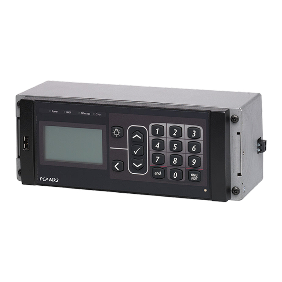
EchoDIN Power Control Processor Mk2
Overview
The Power Control Processor Mk2 is the DIN rail mounted user interface for an EchoDIN system. It
features up and down arrows for menu navigation, a numeric keypad for direct selection, an easy
to read graphical LCD and connections for relay control, Ethernet port on the bottom, USB port on
the front left side, and control option cards.
Note:
information on updating software, see the Power Control Processor Mk2 Configuration
Manual or the most recent software release note.
Note:
Note:
grounded NEMA style box. ETC recommends using a box with a locking door to reduce
electrostatic interference.
For additional information on programming the EchoDIN-PCP-Mk2, see the Power Control
Processor Mk2 Configuration Manual. All ETC documentation is available for free download at
etcconnect.com.
Note:
control terminations are complete to reduce the likelihood of damage to the controller.
Install the Controller
1. Hook top lip of DIN rail mounting clips over the top edge of the
DIN rail in the relay panel.
2. Rock the PCP-Mk2 downward and push firmly until the lower
portion of the clips are secured behind the lower edge of the
DIN rail.
Corporate Headquarters n Middleton, WI, USA | +1 608 831 4116
Global Offices n London, UK | Rome, IT | Holzkirchen, DE | Paris, FR | Hong Kong | Dubai, UAE | Singapore
New York, NY | Orlando, FL | Los Angeles, CA | Austin, TX | © 2023 Electronic Theatre Controls, Inc.
Web
Trademark and patent info:
Product information and specifications subject to change. ETC intends this document to be provided in its entirety.
7123M2141 Rev E Released 2023-10
For EchoDIN, make sure that the PCP-Mk2 has v4.1.0 or later software. For more
For installation by skilled personnel only.
For indoor installation only. The EchoDIN-PCP-Mk2 can be installed in any
It is best to install the Power Control Processor Mk2 after rough-in, load, and
etcconnect.com
| Support
support.etcconnect.com
etcconnect.com/ip
| Contact
etcconnect.com/contactETC
| Third-party license agreement
info: etcconnect.com/licenses
Advertisement

Related Manuals for ETC EchoDIN Power Control Processor Mk2


Summary of Contents for ETC EchoDIN Power Control Processor Mk2
- Page 1 Note: For indoor installation only. The EchoDIN-PCP-Mk2 can be installed in any grounded NEMA style box. ETC recommends using a box with a locking door to reduce electrostatic interference. For additional information on programming the EchoDIN-PCP-Mk2, see the Power Control Processor Mk2 Configuration Manual.
-
Page 2: System Overview
ETC Installation Guide Power Control Processor Mk2 System Overview The following graphic shows the available components for an EchoDIN system. Not all components need to be installed in a single DIN rail enclosure, but consider harness lengths and maximum data transmission distance when laying out a system. - Page 3 ETC Installation Guide Power Control Processor Mk2 System Component ETC Model Number Wire Specification Notes EchoDIN breakers: one for the PCP- Mk2 and one for each relay and dimmer are required EchoDIN relay modules: three modules 4x16 A Relay E-DIN-4RELAY One ribbon cable (not For use with...
-
Page 4: Electrical Specifications
Recommended Cable Notes DMX In and DMX Thru Belden 9729 Contact ETC for list of equivalents. DMX is RS485 serial and can be installed in series (i.e. daisy-chain) topology. Ethernet Belden 1583A (Category Install per EIA/TIA 568B. Test to TSB 67 standards. - Page 5 ETC Installation Guide Power Control Processor Mk2 PCP-Mk2 Connections (bottom edge) A User Interface G S1 switch B Relay module control connection H S2 switch C Emergency Out I Primary/Secondary switch D Emergency In J Option 2 E DMX In K Option 1 F DMX Thru...
- Page 6 ETC Installation Guide Power Control Processor Mk2 Connect an Emergency Contact The EchoDIN can be connected to an external emergency circuit. Emergency can be triggered by a normally open (NO) or normally closed (NC) contact input. In addition, the PCP-Mk2 offers a +24 VDC (maximum 25 mA) Emergency Out that provides a feed to a lamp or LED, indicating...
- Page 7 ETC Installation Guide Power Control Processor Mk2 Connect DMX DMX termination instructions are included with the DMX termination kit that is included with the PCP-Mk2. The default setting for the DMX termination switch, S1 on the termination I/O board, is Off. When you complete the DMX data connections, you must set the S1 switch to On to properly terminate the DMX line.
-
Page 8: Option Cards
ETC Installation Guide Power Control Processor Mk2 Option Cards Each option card in the system includes a wire harness for connecting to the PCP-Mk2. 0-10V Option Contact Input Option The EchoDIN 0–10V Option Card (E-DIN-LVD) The EchoDIN Contact Input Option Card... - Page 9 ETC Installation Guide Power Control Processor Mk2 Primary/Secondary Switch When using a combination of two option cards in an EchoDIN controller, you must position the Primary/Secondary switch prior to startup. The Primary/Secondary switch controls which set of circuits responds to each option card.
- Page 10 ETC Installation Guide Power Control Processor Mk2 Note: You cannot assign the same 24 control circuits to both a 0-10V Option Card and a DALI Option Card. Each group of 24 control circuits may be assigned to a single low- voltage dimming control option card (0–10 V or DALI) and/or to a Contact Input Option...
- Page 11 ETC Installation Guide Power Control Processor Mk2 3. Notice each connector is labeled for your wire termination reference. Using a 3 mm flatblade screwdriver, loosen the terminals and insert each of the data + and data - wire set into the appropriate terminal for the circuit.
- Page 12 ETC Installation Guide Power Control Processor Mk2 Connect Wiring to the DALI Option Card Note: Control wiring must be routed in separate conduit from the line voltage wiring for DALI ballasts. E-DIN-DALI can control up to 24 loops of 64 DALI-compatible ballasts.
- Page 13 ETC Installation Guide Power Control Processor Mk2 A PCP-Mk2 D PCP-Mk2 option card connection B 0–10 V option card E Option card connection C DALI option card Connect Control Wiring on page 4 for a detailed view of connections on the bottom of the PCP-Mk2.
- Page 14 • Disabled: Contact input is disabled when there is no contact input source available for the circuit. For additional information on Contact Input card setup and programming, see the Power Control Processor Mk2 Configuration Manual . ETC manuals are available for free download at etcconnect.com. Remove an Option Card from DIN rail If you need to remove an option card for service or inspection, follow these steps: 1.
- Page 15 ETC Installation Guide Power Control Processor Mk2 Compliance For complete product documentation, including compliance documentation, visit etcconnect.com/products. Power Control Processor Mk2 Page 15 of 15...
Need help?
Do you have a question about the EchoDIN Power Control Processor Mk2 and is the answer not in the manual?
Questions and answers