
Related Manuals for ETC Unison Mosaic


Summary of Contents for ETC Unison Mosaic
- Page 1 Unison Mosaic Hardware Installation Guide Revision H Part Number: 7180M2121 Rev H Released: 2021-08...
- Page 2 To view a list of ETC trademarks and patents, go to etcconnect.com/ip. All other trademarks, both marked and not marked, are the property of their respective owners. ETC intends this document, whether printed or electronic, to be provided in its...
-
Page 3: Table Of Contents
CONTENTS CONTENTS Section 1 - Welcome 1.1 - Overview 1.2 - Software Installation Section 2 - MSC 2.1 - MSC Installation 2.2 - MSC Layout 2.3 - MSC Versions 2.4 - Power Supply 2.5 - Grounding 2.6 - Realtime Clock Battery 2.7 - Memory Card 2.8 - Status LEDs 2.9 - Error Codes... - Page 4 CONTENTS 4.5 - Status LEDs 4.6 - Error Codes 4.7 - Reset Switch 4.8 - Ports Section 5 - MSC X 5.1 - MSC X Installation 5.2 - MSC X Layout 5.3 - MSC X Versions 5.4 - Power Supply 5.5 - Grounding 5.6 - Realtime Clock Batteries 5.7 - Memory Card 5.8 - Status LEDs 5.9 - Error Codes...
- Page 5 CONTENTS 7.5 - Grounding 7.6 - Realtime Clock Batteries 7.7 - Memory Storage 7.8 - Status LEDs 7.9 - Error Codes 7.10 - Reset Switch 7.11 - Watchdog 7.12 - Ports Section 8 - MRIO 8.1 - MRIO Installation 8.2 - MRIO Layout 8.3 - MRIO Versions 8.4 - Power Supply 8.5 - Grounding...
- Page 6 CONTENTS 10.4 - Realtime Clock Battery 10.5 - Memory Card 10.6 - Status LEDs 10.7 - Error Codes 10.8 - Reset Switch 10.9 - Config Switch 10.10 - Watchdog 10.11 - Learning IR Receiver 10.12 - Temperature Sensor Section 11 - NET 11.1 - NET Installation 11.2 - NET Layout 11.3 - Power Supply...
- Page 7 CONTENTS 13.10 - LED Fixture Types (Low Voltage Architectural Only) 13.11 - Fixture Ganging 13.12 - LED-x Version & Power Supply Selection Compliance...
- Page 8 [This page intentionally left blank]...
-
Page 9: Section 1 - Welcome
SECTION 1 - WELCOME SECTION 1 - WELCOME Thank you for purchasing an ETC product, we hope that it fulfills your expectations and provides a lifetime of reliable service. If you have any questions or require technical support please contact: ETC Support... -
Page 10: Section 2 - Msc
0°C to 50°C (32°F to 122°F). Sealed IP65 rated consumer units are available for outdoor use, please consult your Unison Mosaic distributor or representative. Since the units require no user intervention once installed they are suitable for remote installation with all configuration and management taking place over an Ethernet network. -
Page 11: Power Supply
SECTION 2 - MSC a stand-alone controller or co- operatively, via an Ethernet network, to form a scalable system. 2.4 - POWER SUPPLY The MSC can be powered in two different ways: DC power (9 to 48V) A limited power source approved to UL60950-1 2nd Edition, CAN/CSA C22.2 No. -
Page 12: Grounding
2.8 - STATUS LEDS The ETC logo will illuminate when power is applied to the MSC. The red LEDs on the front of the MSC indicate the unit’s current status. The Active LED illuminates once the boot up procedure has completed and is... -
Page 13: Error Codes
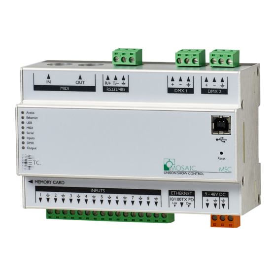
SECTION 2 - MSC The Ethernet LED indicates Unison Mosaic-related network activity (not network link, see Ethernet port later) while the remaining LEDs indicate communication on the various ports of the MSC. The Output LED indicates that a valid project file has been loaded from the memory card and that playback &... - Page 14 SECTION 2 - MSC In RS232 mode, the port operates in full duplex with the following pinout: R/+ Receive T/- Transmit Signal ground In RS485 (and DMX In) mode, the port operates in half duplex with the following pinout: R/+ Data + T/- Data - Signal Ground The serial port is not isolated from the MSC’s power supply.
- Page 15 SECTION 2 - MSC The DMX ports are by default not isolated from the MSC’s ground connection which is the recommended configuration for driving isolated inputs - the majority of DMX receivers. If required this may be changed by removing the top cover of the MSC and removing the jumper marked ‘JP1’, located to the right of the DMX ports.
- Page 16 SECTION 2 - MSC In all modes, all signal ground pins are connected together internally. The digital/analog inputs are not isolated from each other nor the MSC’s power supply. If isolation is required, it must either be provided by the connected device or a separate isolator should be used.
-
Page 17: Section 3 - Mtpc
The Tessera Panel Controller (MTPC) is a fully fledged Controller in its own right with an integrated touch screen user interface. It can also share its user interface with other Unison Mosaic Controllers when operating as part of a system across an Ethernet network. -
Page 18: Mtpc Layout
SECTION 3 - MTPC 3.2 - MTPC LAYOUT The following drawing illustrates the layout of a MTPC, refer to the following sections for details: 3.3 - POWER SUPPLY Power-over-Ethernet (PoE) A standard (802.3af) Power-over-Ethernet switch should be used to provide both power and a network connection to the MTPC using a single cable. -
Page 19: Realtime Clock Battery
SECTION 3 - MTPC Alternatively, the TPC-RIO can be used to provide power and a data connection to the MTPC. A limited power source approved to UL60950-1 2nd Edition, CAN/CSA C22.2 No. 60950- 1.07 2nd Edition MUST be used, with an SELV output voltage. The MTPC operates as a PoE Class 2 device (3.84-6.49W) and will typically consume 4W. -
Page 20: Status Leds
SECTION 3 - MTPC 3.6 - STATUS LEDS The LEDs on the rear of the unit provide the following status information: Pwr: Power - illuminates when the unit is correctly powered. Act: Active - illuminates once the boot up procedure has completed and is indicative of a fully functional unit. -
Page 21: Config Switch
SECTION 3 - MTPC NOTE: The reset must not be operated during firmware updates to the MTPC as corruption of the software may occur, perhaps even rendering the unit inoperable. 3.9 - CONFIG SWITCH The MTPC may be placed in a configuration mode by removing the magnetic overlay and pressing the config switch, refer to Designer Help for instructions. -
Page 22: Section 4 - Tpc-Rio
SECTION 4 - TPC-RIO SECTION 4 - TPC-RIO 4.1 - TPC-RIO INSTALLATION The TPC-RIO is designed to be permanently installed in a central control room/cupboard or DIN consumer unit for remote deployment. The enclosure and mounting complies with DIN43880 and EN60715 (35/7.5 rail) respectively. The units are 100% solid state and have been qualified to operate in a dry environment within a temperature range of 0°C to 50°C (32°F to 122°F). -
Page 23: Power Supply
The TPC-RIO must be correctly grounded to electrical safety earth at all times. 4.5 - STATUS LEDS The ETC logo will illuminate when power is applied to the TPC-RIO. The red LEDs on the front of the TPC-RIO indicate the unit's current status. -
Page 24: Error Codes
4.8 - PORTS RS232 Serial Port The serial port's data rate and format settings (baud, parity, stop bits, etc.) are configured using Designer. The port operates in full duplex with the following pinout: R/+ Receive T/- Transmit... - Page 25 SECTION 4 - TPC-RIO The serial port is not isolated from the TPC-RIO’s power supply. If isolation is required, it must either be provided by the connected device or a separate isolator should be used. DMX Output The pins on this connector are marked: + Data + (‘Hot’...
- Page 26 SECTION 4 - TPC-RIO Analog input: An external voltage source (such as a 0-10VDC analog signal) may be connected between the input pin and the signal ground pin. In this mode, the input pin is internally pulled down to 0V via a 2Mohm resistor and the maximum input voltage supported is 24VDC.
- Page 27 SECTION 4 - TPC-RIO NOTE: MTPC PoE port is designed to work with the MTPC alone. Connecting any other Unison Mosaic or third party devices to this port could damage the device and/or the TPC-RIO. Ethernet A standard 10/100TX Ethernet connection may be made to the TPC-RIO. The LEDs on the RJ45 jack itself are useful for debugging the Ethernet installation: The Lnk LED will illuminate when an Ethernet link has been established.
-
Page 28: Section 5 - Msc X
The MSC X is fitted with fan filters mounted on the front panel of the product. Should the filters become clogged, they need to be replaced. Please contact ETC Technical Services for further information. 5.2 - MSC X LAYOUT The following drawings illustrate the layout of the MSC X, refer to the following sections for details: 5.3 - MSC X VERSIONS... -
Page 29: Power Supply
20 DMX universes (10,240 channels) while the MSC 100 can control 100 DMX universes (51200 channels). The MSC X can be used as a stand-alone controller or co-operatively with other Unison Mosaic Controllers and Remote Devices, via an Ethernet network, to form a scalable system. 5.4 - POWER SUPPLY The MSC X is mains powered via a fused, universal input power supply unit (PSU) -
Page 30: Memory Card
5.8 - STATUS LEDS The ETC logo will illuminate when power is applied to the MSC X. The red LEDs above indicate the unit’s current status. The Active LED flashes throughout the boot up procedure and lights solidly once this has been completed and is indicative of a fully functional unit. -
Page 31: Reset Switch
5.12 - PORTS Ethernet 1 - MGMT A standard 10/100/1000BASE-T Ethernet connection may be made to this port for management and networking to other Unison Mosaic Controllers and Remote Devices. Ethernet 2 - DATA A standard 10/100/1000BASE-T Ethernet connection may be made to this port to output data to lighting fixtures using Ethernet protocols (eDMX) such as ArtNet and KiNet. - Page 32 SECTION 5 - MSC X 4: DTR 5: Signal ground 6: DSR 7: RTS 8: CTS 9: RI The serial port is not isolated from the MSC X’s power supply. If isolation is required, it must either be provided by the connected device or a separate isolator should be used.
-
Page 33: Section 6 - Atlas
The Atlas is fitted with fan filters mounted on the front panel of the product. Should the filters become clogged, they need to be replaced. Please contact ETC Technical Services for further information. 6.2 - ATLAS LAYOUT... -
Page 34: Atlas Versions
50 DMX universes (25,600 channels) while the Atlas 1500 can control 1500 DMX universes (768,000 channels). The Atlas can be used as a stand-alone controller or co-operatively with other Unison Mosaic Controllers and Remote Devices, via an Ethernet network, to form a scalable system. 6.4 - POWER SUPPLY The Atlas is mains powered via an internally fused, universal input power supply unit (PSU) compatible with all worldwide mains supply standards;... -
Page 35: Memory Storage
6.8 - STATUS LEDS The ETC logo will illuminate when power is applied to the Atlas. The red LEDs above indicate the unit’s current status. The Active LED flashes throughout the boot up procedure and lights solidly once this has been completed and is indicative of a fully functional unit. -
Page 36: Watchdog
6.12 - PORTS Ethernet 1 - MGMT A standard 10/100/1000BASE-T Ethernet connection may be made to this port for management and networking to other Unison Mosaic Controllers and Remote Devices. Ethernet 2 - DATA A standard 10/100/1000BASE-T Ethernet connection may be made to this port to output data to lighting fixtures using Ethernet protocols (eDMX) such as ArtNet and KiNet. - Page 37 SECTION 6 - ATLAS The serial port is not isolated from the Atlas’s power supply. If isolation is required, it must either be provided by the connected device or a separate isolator should be used. DVI-I Input A standard DVI connection may be made to this port to route video data to a Live Video Preset within the project.
-
Page 38: Section 7 - Atlas Pro
The Atlas Pro is fitted with fan filters mounted on the front panel of the product. Should the filters become clogged, they need to be replaced. Please contact ETC Technical Services for further information. NOTE: This equipment is not suitable for use in locations where children are... -
Page 39: Atlas Pro Layout
50 can control 50 DMX universes (25,600 channels) while the Atlas Pro 3000 can control 3000 DMX universes (1,536,000 channels). The Atlas Pro can be used as a stand-alone controller or co-operatively with other Unison Mosaic Controllers and Remote Devices, via an Ethernet network, to form a scalable system. 7.4 - POWER SUPPLY The Atlas Pro is mains powered via an internally fused, universal input power supply unit (PSU) compatible with all worldwide mains supply standards;... - Page 40 7.8 - STATUS LEDS The ETC logo will illuminate when power is applied to the Atlas Pro. The red LEDs above indicate the unit’s current status. The Active LED flashes throughout the boot up procedure and lights solidly once this has been completed and is indicative of a fully functional unit.
- Page 41 7.12 - PORTS Ethernet 1 - Management A standard 10/100/1000BASE-T Ethernet connection may be made to this port for management and networking to other Unison Mosaic Controllers and Remote Devices. Ethernet 2 - Data A standard 10/100/1000BASE-T Ethernet connection may be made to this port to output data to lighting fixtures using Ethernet protocols (eDMX) such as ArtNet and KiNet.
- Page 42 SECTION 7 - ATLAS PRO DVI-I Output A standard DVI connection may be made to this port to route output data to the lighting fixtures using the Digital Video Interface. RS232 Serial Port The serial ports may be connected directly to a PC using a null modem cable. Other devices may require different cables depending on their pinout.
- Page 43 SECTION 7 - ATLAS PRO CAUTION: Ports and third party equipment can be damaged when plugging or unplugging an energised system (hot-plugging). Remove power before making or breaking port connections. ATTENTION: Les ports et l'équipement d'un tiers peuvent être endommagés lors du branchement ou du débranchement d'un système sous tension (branchement à...
- Page 44 SECTION 8 - MRIO SECTION 8 - MRIO 8.1 - MRIO INSTALLATION The Remote Input/Output Devices (MRIO) are ancillary devices that provide additional input and output interfaces to a system. As such, they can not be used on their own but must have at least one Controller present on an Ethernet network to function.
- Page 45 MRIO 08 only). 8.6 - STATUS LEDS The ETC logo will illuminate when power is applied to the MRIO. The red LEDs on the front of the MRIO indicate the unit's current status. The Active LED flashes slowly once the boot up procedure has completed to indicate a fully functional unit.
- Page 46 SECTION 8 - MRIO The Ethernet LED indicates Unison Mosaic-related network activity (not network link, see Ethernet port later) while the remaining LEDs indicate communication on the various ports of the MRIO. 8.7 - ERROR CODES Additionally the red status LEDs are used to indicate any boot failures of the MRIO that prevent the unit from operating.
- Page 47 SECTION 8 - MRIO 8.10 - WATCHDOG An internal "watchdog" will automatically reset the MRIO in case of a software crash as a result of either a coding error ("bug") or a random electromagnetic event such as a power brown-out or spike, nearby lightning strike or static discharge. 8.11 - PORTS ...
- Page 48 RS232/RS485/DMX Serial Port (MRIO 80, MRIO 44 and MRIO 08 only) The serial port's protocol (RS232 or RS485), data rate and format settings (baud, parity, stop bits, etc.) are configured using Designer. The port can additionally be configured to output 96 channels of DMX512 control data (RDM is not supported).
- Page 49 SECTION 8 - MRIO Balanced audio right channel + Balanced audio right channel - (tie to ground for unbalanced) Signal ground Balanced audio left channel + Balanced audio left channel - (tie to ground for unbalanced) Signal ground The audio input can also accept linear time code (LTC) such as SMPTE/EBU on either channel but not both, configured using Designer.
- Page 50 SECTION 9 - BPS SECTION 9 - BPS 9.1 - BPS INSTALLATION The Button Panel Stations (BPS) are ancillary devices that provide user interfaces to a system. As such, they can not be used on their own but must have at least one Controller present on an Ethernet network to function.
- Page 51 SECTION 9 - BPS 9.3 - BPS LAYOUT The following drawing illustrates the layout of a Unison Mosaic Button Panel Station (UK shown with overlay removed), refer to the following sections for details: 9.4 - POWER SUPPLY Power-over-Ethernet (PoE) A standard (802.3af) Power-over-Ethernet switch should be used to provide...
- Page 52 Restored firmware is corrupt Codes 2 through 6 indicate a hardware error; please consult your distributor, representative or ETC Technical Services for assistance. 9.7 - ADDRESS WHEEL Multiple BPSs may be used on a single network. Each BPS is uniquely identified by its address setting.
-
Page 53: Learning Ir Receiver
SECTION 9 - BPS manual ('M') setting should be used to allow identification using the BPS's serial number rather than the address. 9.8 - RESET SWITCH The BPS may be reset by removing the magnetic overlay and inserting a small blunt object into the reset hole to depress the reset switch. - Page 54 The buttons will now revert to normal operation. Network communication will resume. Note that the BPS does not have to be part of a networked Unison Mosaic system to learn IR codes, all that is required is PoE power and the donor IR remote control.
- Page 55 SECTION 10 - M-TS SECTION 10 - M-TS 10.1 - M-TS INSTALLATION The Touchscreen Station (M-TS) is an interface device with an integrated touch screen user interface. It is an ancillary device that provides a user interface to a system. As such, they can not be used on their own but must have at least one Controller present on an Ethernet network to function.
- Page 56 SECTION 10 - M-TS 10.2 - M-TS LAYOUT The following drawing illustrates the layout of a Unison Mosaic Touchscreen Station, refer to the following sections for details: 10.3 - POWER SUPPLY Power-over-Ethernet (PoE) A standard (802.3af) Power-over-Ethernet switch should be used to provide both power and a network connection to the M-TS using a single cable.
- Page 57 SECTION 10 - M-TS NOTE: Power must not be disconnected during firmware updates to the M-TS as corruption of the software may occur, perhaps even rendering the unit inoperable. 10.4 - REALTIME CLOCK BATTERY The M-TS’s internal realtime clock is battery-backed to ensure operation when the unit is not powered.
-
Page 58: Temperature Sensor
SECTION 10 - M-TS Eth: Ethernet - illuminates when the unit is sending or receiving Unison Mosaic-related data. Out: Output - not currently used (except for error codes). 10.7 - ERROR CODES Additionally the red status LEDs are used to indicate any boot failures of the M-TS that prevent the unit from going active. -
Page 59: Section 11 - Net
SECTION 11 - NET 11.1 - NET INSTALLATION The Unison Mosaic 2+4 port Power-over-Ethernet Switch (NET) is designed to be permanently installed in a central control room/cupboard or DIN consumer unit for remote deployment. The enclosure and mounting complies with DIN43880 and EN60715 (35/7.5 rail) respectively. -
Page 60: Power Supply
The NET is capable of powering up to four IEEE 802.3af Class 1,2 and 3 and IEEE 802.3at Class 4 (Type 2) devices, the power supply required can be calculated using the table below: Example Unison Mosaic Maximum PSU Power Class... -
Page 61: Grounding
Chassis ground (earth) terminal is also provided which should be connected to a suitable earth. 11.6 - STATUS LEDS The ETC logo will illuminate when power is applied to the NET. The red LEDs on the top of the NET indicate the unit's status: Active: Indicates that the unit is functional. -
Page 62: Section 12 - Opto
SECTION 12 - OPTO 12.1 - OPTO INSTALLATION The Unison Mosaic 1+4 port DMX512 Repeater (OPTO) is designed to be permanently installed in a central control room/cupboard or DIN consumer unit for remote deployment. The enclosure and mounting complies with DIN43880 and EN60715 (35/7.5 rail) respectively. -
Page 63: Power Supply
Chassis ground (earth) terminal is also provided which should be connected to a suitable earth. 12.5 - STATUS LEDS The ETC logo will illuminate when power is applied to the OPTO. The red LEDs on the top of the OPTO indicate the unit's status: Active: Indicates that the unit is functional. - Page 64 SECTION 12 - OPTO Such compliance is beyond the scope of this document but a good resource is "Recommended Practice in DMX 512" by Adam Bennette which is available through PLASA and USITT .
-
Page 65: Section 13 - Led-X
SECTION 13 - LED-X 13.1 - LED-X INSTALLATION The Unison Mosaic LED Drivers (LED-x) are ancillary devices that provide direct LED control. As such, they can not be used on their own but must have at least one Controller (MSC 1/2/4) or Remote Input/Output Device (MRIO 80/44/08) present to provide the DMX control data. -
Page 66: Led-X Versions
Chassis ground (earth) terminal is also provided which should be connected to a suitable earth. 13.6 - STATUS LEDS The ETC logo will illuminate when power is applied to the LED-x. The red LEDs on the top of the LED-x indicate the unit's status: Active: Indicates that the unit is functional. -
Page 67: Dmx Thru Termination
SECTION 13 - LED-X 13.7 - DMX THRU TERMINATION If the DMX Thru connection is not being used to daisy-chain to other DMX devices then the supplied termination resistor MUST be fitted to ensure data integrity. 13.8 - DMX & RDM GUIDELINES The LED-x is compatible with the DMX512, DMX512(1990), DMX512-A and RDM 1.0 standards and care should be taken to ensure that your cabling, wiring topology and termination also complies with these standards. - Page 68 SECTION 13 - LED-X So before you can select the correct LED driver you must determine the fixture type and then gather the drive characteristics from the manufacturer: LED MODULE - CONSTANT CURRENT DRIVE Module forward current If(module) which is typically 350, 500 or 700mA Module forward voltage Vf(module) which is module power divided by If (module) LED ARRAY - CONSTANT VOLTAGE DRIVE...
- Page 69 SECTION 13 - LED-X LED ARRAY - GANG IN PARALLEL All arrays must have the same supply voltage Vs(array) to be ganged Determine the total power load Ps(total) by summing the Ps(array)s It is helpful to end up with similar Ps(total)s for each gang of arrays 13.12 - LED-X VERSION &...
- Page 70 COMPLIANCE COMPLIANCE The ETC product range is manufactured to the highest quality in compliance with the following international standards: ENCLOSURE AND MOUNTING EN60715: Top hat section (TH) 35-7.5mm & 35-15mm DIN rail. DIN 43 880: Built-in equipment for electrical installations; Frame size 1.
- Page 71 | Support support.etcconnect.com Contact etcconnect.com/contactETC | © 2021 Electronic Theatre Controls, Inc. Trademark and patent info: etcconnect.com/ip | Product information and specifications subject to change. ETC intends this document to be provided in its entirety. 7180M2121 Rev H Released 2021-08...
Need help?
Do you have a question about the Unison Mosaic and is the answer not in the manual?
Questions and answers