Table of Contents
Advertisement
Quick Links
Echoflex Installation Guide
LED Fixture Controller
Overview
The ELED1 Fixture Controller provides wireless control of individual fixture or
single zone lighting based on occupancy state, manual switch action,
ambient light levels, and gateway commands.
This document covers installation of the ELED1 LED Fixture Controller
models. The Echoflex LED Fixture Controller ELED1(H) Configuration Guide
is available for download at echoflexsolutions.com.
The package contents includes the controller, installation guide, and
mounting strap (for ELED1-BUS model).
Prepare for Installation
Echoflex recommends paying special attention to the installation
environment.
• High density construction materials and large metal appliances or
fixtures in the space may disrupt wireless reception.
• Mount the controller to an electrical junction box or a panel in a
location and at a height where it is not subject to tampering by
unauthorized personnel.
Supplies required to install the controller (not provided):
• Appropriately sized wire nuts
• Wire insulation
• Small cable ties
• Two 3/8 inch #8 metal screws (for surface mounting strap only)
Corporate Headquarters Middleton, WI, USA
Web
echoflexsolutions.com
© 2021 Echoflex Solutions, Inc. Trademark and patent info:
Echoflex intends this document to be provided in its entirety. Product information and specifications subject to change.
8189M2100 Rev A Released 2021-03
ELED1-BUN
|
Phone +1 608 831 4116
|
Email
info@echoflexsolutions.com
BUS
|
Support
support.etcconnect.com
echoflexsolutions.com/ip
ELED1-BUS
Violet
Advertisement
Table of Contents

Related Manuals for ETC Echoflex ELED1-BUN


Summary of Contents for ETC Echoflex ELED1-BUN
- Page 1 Echoflex Installation Guide LED Fixture Controller Overview The ELED1 Fixture Controller provides wireless control of individual fixture or single zone lighting based on occupancy state, manual switch action, ambient light levels, and gateway commands. ELED1-BUN ELED1-BUS Violet This document covers installation of the ELED1 LED Fixture Controller models.
-
Page 2: Important Safeguards
Echoflex Installation Guide LED Fixture Controller IMPORTANT SAFEGUARDS READ AND FOLLOW ALL SAFETY INSTRUCTIONS WARNING: Risk of electric shock! This device utilizes high voltage and should only be installed by a qualified installer or electrician. Follow all local codes for installation. Before terminating the AC power wiring verify that the main breaker is in the off position and follow the proper lockout/tag out procedures per NFPA Standard 70E. -
Page 3: Installation
Echoflex Installation Guide LED Fixture Controller Installation All local codes and standard electrical practices should be observed. Ensure that the junction box is clean and free of obstructions and that all wiring is installed correctly. Note: Follow applicable NEC and local electrical code requirements when installing and powering the controller. -
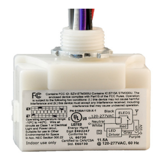
Page 4: Wiring Diagram
Echoflex Installation Guide LED Fixture Controller 4. Refer to the wiring diagram to connect the controller to line power, neutral, and load wires. Use wire nuts on all connections and individually cap any bare wires, except the orange antenna wire. 5. - Page 5 Echoflex Installation Guide LED Fixture Controller Diagram 2 of 2 Normal Hot Normal Neutral ELED1 Load Control Ba ery ELED1 Backup LED - LED + Dimming - Dimming + LED Driver Hot LED + Emi er Driver Board LED - Electrical Terminations Power to the controller is connected between the White (Neutral) and the Black Line power (120–277 VAC).
-
Page 6: Controller Interface
Echoflex Installation Guide LED Fixture Controller Controller Interface The controller interface has two LEDs and two buttons. LEDs ELED1-BUS 120-277 Led Fixture Controller Clear Button The Power LED (red) and Learn LED Learn Button Power Learn (green) indicate whether the controller is providing information via blink codes or is Blink Codes in an operational mode. - Page 7 Echoflex Installation Guide LED Fixture Controller • In factory default state, when powered up, the Power LED displays solid red to indicate the controller has no linked devices. To test the relay(s), press the [Learn] button or link a switch. See relevant switch documentation.
- Page 8 Echoflex Installation Guide LED Fixture Controller Operations Activity Power LED Learn LED Relay/Light Link mode Blink On solid Toggle Store link ID On 4 seconds On solid On 4 seconds Clear link ID Off 4 seconds On solid Off 4 seconds One blink Factory default On solid...
Need help?
Do you have a question about the Echoflex ELED1-BUN and is the answer not in the manual?
Questions and answers