Table of Contents
Advertisement
Quick Links
Architectural Control Processor
Configuration Manual
2.0.1
C o p y r i g h t © E le c tr o n i c T h e a t r e C o n t r o l s , I n c .
A l l R i g h t s r e s e r v e d .
P r o d u c t in f o r m a t i on a n d s p e c i f i c a t i o n s s u bj e c t t o c h a n g e .
P a r t N u m b e r : 7180M1230-2.0.1 R e v A
R e le a s ed : 2 0 1 2 - 0 1
Advertisement
Table of Contents

Related Manuals for ETC P-ACP


Summary of Contents for ETC P-ACP
- Page 1 Architectural Control Processor Configuration Manual 2.0.1 C o p y r i g h t © E le c tr o n i c T h e a t r e C o n t r o l s , I n c . A l l R i g h t s r e s e r v e d .
- Page 2 ® ® ® ® ET C , U n i s o n , E T C N e t 2 ™ , N e t3 ™ , S en s o r , Sm a r t L in k , a n d P a r a d i g m ™...
-
Page 3: Table Of Contents
Contacting ETC ........3... - Page 4 Dimmer Setup ........30 Patch By DMX Start.
- Page 5 A p p e n d i x A Paradigm ACP Menu Flow Chart ..75 Menu Flow Chart ........76 A p p e n d i x B Dimmer Specifications .
-
Page 6: Introduction
This manual contains information for user configuration and programming of the Paradigm ACP when installed in a Unison DRd or ERn enclosure. The Paradigm architectural control processor (P-ACP) is an integrated hardware and software solution for complete configuration and control of dimmers, LED fixtures, DMX- based moving lights, conventional and architectural fixtures, and Heritage and Paradigm control stations. -
Page 7: Warnings And Notice Conventions
W a r n i n g s a n d N o t i c e C o n v e n t i o n s These symbols are used throughout ETC documentation to alert you to danger or important... -
Page 8: Contacting Etc
For technical questions about Unison rack systems, contact ETC Technical Services directly at one of the offices listed below. Emergency service is available from all ETC offices outside of normal business hours. When calling for assistance, please be near the equipment for troubleshooting and have the following information handy: •... -
Page 9: Overview
The Paradigm architectural control processor (P-ACP) is one component of the Paradigm control system. A Paradigm ACP is designed to fit in the bottom module slot of either a DRd or ERn enclosure and provides an intuitive user interface into the Paradigm system. The... - Page 10 OUTPUTS INPUTS OUTPUTS RS-232 7183B4605 REV C © 2012 ETC, INC. MADE IN THE U.S.A. J5 INPUTS • RS-232 (serial) on a male 9 pin (D style) connector. This connection typically requires a null modem (i.e. cross-over) cable between RS-232 sources without 3rd party signal ®...
- Page 11 N o t e : Check the pin-out of the connected RS-232 service to ensure correct pairing of transmit and receive lines. The RS-232 cable (not supplied) should follow common RS-232 pinout for a DB- 9 receptacle (pin 2 is RS-232 Rx, pin 3 is RS-232 Tx, and pin 5 is ground).
-
Page 12: Installation Environment Requirements
Installation Environment Requirements The Paradigm ACP is designed for use in a Unison DRd or ERn enclosure. The environmental conditions for the Paradigm ACP should adhere to the requirements set for the host enclosure. Reference the related enclosure Installation manual for complete details. -
Page 13: Installation And User Interface Overview
C h a p t e r 1 Installation and User Interface Overview This chapter contains the following sections: • Install the Paradigm ACP ......9 •... -
Page 14: Install The Paradigm Acp
Install the Paradigm ACP The Paradigm architectural control processor (P-ACP) is designed to slide in the bottom module slot of a Unison DRd or an ERn enclosure. All data terminations used with the Paradigm ACP are terminated to the right and left I/O boards in the related enclosure. Install the Paradigm ACP only after the enclosure has been installed and all wires have been terminated properly. -
Page 15: System Status
Single Processor System LightDesigner configurations with only a single processor will automatically resolve processor number (identity) and IP settings when loaded onto a processor. No additional setup is required. Step 1: Use removable media to load the LightDesigner configuration file. See “Load Architectural Configuration”... -
Page 16: User Interface Overview
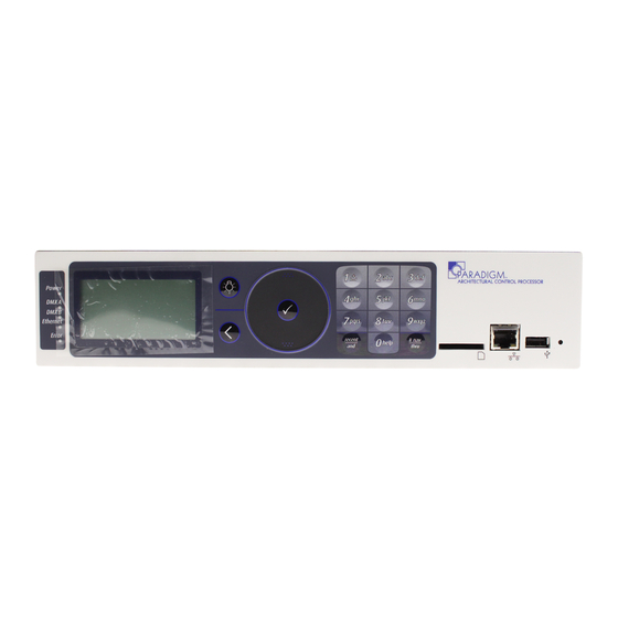
User Interface Overview The Paradigm ACP features a dynamic user interface with a touch wheel for easy menu navigation, an alpha-numeric button pad for direct selection, and a bright, easy to read graphic LCD. Additionally, an SD media card slot, integrated USB port for flash drive, and an Ethernet port for PC connection to LightDesigner for configuration transfers are provided. -
Page 17: Enter
#nav shortcuts is enabled, or to enter a specific value such as a dimmer number, intensity value, etc., while in a selectable menu. Additionally, the button pad may be used to alpha- numerically search the menu. When a “abc” graphic is displayed in the right corner of the display, alpha-numeric searching may be used. - Page 18 • Alternatively, while navigating certain menu items such as “Dimming Setup” or “Dimming Control” menus and selecting specific dimmers, use the [/and] button to select dimmers out of sequence. For example, [1] [/ and] [5] [/ and] [8] ( ), selects dimmers 1, 5, and 8.
-
Page 19: Removable Media
R e m ov a b l e M e d i a US B Port The Paradigm ACP includes a USB port for use with a flash drive, located on the front panel. The USB flash drive is not included and can be purchased separately. A USB flash drive can be used to store and load backup files of your architectural and dimming configurations. -
Page 20: Reset Switch
R e s e t S w i t c h Reset the Paradigm ACP software and hardware by pressing the reset switch located on the front panel of the unit. Access the reset switch using the tip of a ball point pen, or other pointed object. -
Page 21: Paradigm Acp Basic Navigation
C h a p t e r 2 Paradigm ACP Basic Navigation This chapter contains the following sections: • Status Display ........17 •... -
Page 22: Status Display
Status Di splay The Paradigm architectural control processor (P-ACP) provides all of the basic rack and system information on the status display. When the Paradigm ACP is installed in a DRd enclosure, the dimming rack status display is the default status display. The architectural control status display is the only status display available when the Paradigm ACP is installed in an ERn enclosure. -
Page 23: Arch Control Status Display
• internal operating temperature - The internal operating temperature is measured and displays on the dimming rack status display. By default, temperature is displayed in °F when the rack is 120, 240, or 277 VAC, and in °C when the rack is 230 VAC. •... -
Page 24: Status / Error Messages
Status / Error Messages Status messages display on both the dimming rack status display and the Arch Control Status display. When the Paradigm ACP is installed in a DRd enclosure, use the touch wheel to scroll clockwise ( ) to view the Arch Control Status display. Status messages provide you with system wide, rack specific or even just dimmer specific information including errors. -
Page 25: Status / Error Messages Generated By The Paradigm Acp
20 panel UI by the processor’s name (e.g. Processor / IP settings possible per system. “Processor 1”, “1st Floor West”, etc.). Internal Clock Error / An error displays during Contact ETC Technical Services. Low Battery... -
Page 26: Drd Dimming Engine
S t a t u s / E r r o r s M e s s a g e s G e n e r a t e d b y t h e D R d D i m m i n g E n g i n e Message Displayed Description Action... -
Page 27: Menu Navigation
The numeric button pad or the touch wheel may be used to edit specific objects from the operation menu, such as dimmer number, levels, etc. Once an edit has been made, press the enter ( ) button to accept the selection. -
Page 28: Programming
C h a p t e r 3 Programming This chapter contains the following sections: • About Menu ........24 •... -
Page 29: About Menu
About Menu About The “About Menu” provides you direct access to view 1 About Dimmer details about your dimmers (when the Paradigm ACP is 2 DMX Level Data installed in a host DRd rack), current DMX level data, 3 Version Info software version information, project information, 4 Project Information 5 Statistics... - Page 30 DMX Input Selecting the active input port displays DMX data sorted A: Input DMX Data by the input address. The next column displays the level information for the addresses in the far left column. B:127 100 AN B:128 100 A When there is no active DMX input, the input level B:192 column displays “---”.
-
Page 31: Version Info
V e r s i o n I n f o The “Version Info” menu displays the current full software Version Info version numbers, including build numbers, for each software Paradigm ACP App: type installed in the rack. 1.0.0.0.0.0.05 DRd: 1.0.0.0.0.04 FLO and DALI options only appear if they are presently FLO: 1.0.0.0.0.06 installed in the host DRd rack. - Page 32 sACN Control “sACN Control Stats” provide users a metric for sACN Control Stats resource strain caused by Ethernet based control Totals by: Processor for: Processor 1 using sACN and helps to characterize the sACN sACN Sources: environment for a system. sACN control statistics sACN Universes update every 5 seconds.
-
Page 33: View Message Log
R S 2 3 2 S e r i a l “RS232 Serial” menu includes statistics related to serial RS232 Serial Bytes tx: ##### commands including the bytes sent, bytes received, and Bytes rx: ##### number of errors encountered. If RS232 has never been used Frame Errors: ##### in the system, the counters will display “0”. - Page 34 ID (NID) is shown for devices that are discovered. Found To physically identify a device press the control menu shortcut To identify push key ( ) to send a wink command to the selected device. For Heritage 5 btn Unison Heritage stations the selected station LEDs will blink, [####-####-####] LCD 7”...
-
Page 35: Dimming Setup Menu
Each object in the “Dimmer Setup” menu allows you to specify alternative dimmer properties about each dimmer channel including the dimmer module type, the mode of operation, curve, etc. N o t e : When exiting dimmer setup using the back button ( ), and the DMX patch has been modified, a dialog will display requesting confirmation of patch edits. - Page 36 Dimmer Setup Each module type has a default set of properties such as the From dimmer: 1 to: 3 firing mode, dimmer curve, etc. When changing a module Module Type: type, all dimmer properties for the specified dimmer(s) also Mode: Normal change to match the new module type property defaults.
- Page 37 100 - 120 VAC Racks Module Type Description of Purpose Compatible Loads required in empty dimmer slots not applicable direct connection from line lug to load lugs constant loads such as power supplies CC15 and CC20 protected by 15 or 20 amp circuit breaker or other constant-on loads Incandescent, 2 and 4 wire fluorescent, D15 and D20...
- Page 38 • Dimmer Doubled: dimmer operates as two controllable circuits with two channels of control. This mode is displayed for use only with 120 VAC / 60Hz systems utilizing ETC Dimmer Doubling™. •...
- Page 39 Threshold: Threshold allows you to set a dimmer or a range of dimmers to a specific threshold control level (0-100%) at which it begins to respond. Below that threshold level, the dimmer remains off. The default value is 0%. Step 7: Scroll to “Threshold”...
- Page 40 D y n a m i c P r e h e a t Dynamic preheat is the amount of time a dimmer or selected range of dimmers will maintain a zero output after the control channel is brought to zero from a higher level. After completing that off time it will then fade back up to the minimum scale voltage.
-
Page 41: Patch By Dmx Start
P a t c h B y D M X S t a r t When patching by DMX start address, all dimmers in the rack Patch by DMX Start are set to default address values determined by the DMX Dimmer 1 Start: address of the first dimmer in the rack. -
Page 42: Patch Dimmers
P a t c h D i m m e r s When patching your dimmers using the advanced patch menu, Patch Dimmers you can edit any existing dimmer in your rack that is patched, Mode: Dim: including that which had been set using the “Patch by DMX Start”... -
Page 43: Emergency Setup
Step 2: Assign a DMX address to the first dimmer in the selection and press enter ( The focus changes back to the dimmer number. When dimmer doubling is enabled for a selected dimmer, the focus changes to the second address (b) selection for the affected dimmers. - Page 44 Emergency Dimmers From the Emergency Setup menu, scroll to “Emergency Dimmers” and press enter ( “Emergency Dimmers” displays for dimmer assignment. Assign dimmers to be “On” when the panic input is active and Emergency Dimmers assign other dimmers to turn off (also known as load-shedding). 10: -- 11: O n 13: N A...
- Page 45 L o a d S h e d d i n g Emergency Setup When the DRd enclosure senses the loss of normal power, it Emergency Dimmers bypasses the Paradigm ACP and drives selected emergency Emergency Level: load circuits to the emergency level. Load Shedding: Input Type: Maintained...
-
Page 46: Quick Rack Setup
Q u i c k R a c k S e t u p Quick Rack Setup Quick Rack Setup Voltage L-N Auto Rack Type: Auto Rack Type: Auto Module Type: Module Type: Balance: Straight Balance: Straight DMX Start Addr: DMX Start Addr: Temp: Fahrenheit... - Page 47 Step 3: Use the touch wheel to scroll to the next setup option or scroll to “Apply Changes Only” or “Apply All”. Press enter ( ) to select. B a l a n c e : This setting is automatically defaulted to “Straight”. Other settings include “3 Phase Bal” or “1 Phase Bal”.
-
Page 48: Arch Setup Menu
L o n W o r k s C o n n e c t i o n s The “LonWorks Connections” menu provides visibility of LonWorks Connections all LonWorks devices (stations, sensors, etc.) that are xxx of yyy Connected... -
Page 49: Assign Processor / Ip
“Select New Settings” menu provides default processor name with associated default IP settings for selection. ETC recommends that you use the default settings unless you have specific needs such as a routed IP network or the use of DHCP IP services. -
Page 50: Date/Time/Location
“restore defaults” action. A restore defaults action from the processor face panel changes defaults to match defaults used in LightDesigner (manual/10.101.10.101, etc) and resets the identity to the unassigned processor state. E d i t L o c a l S e t t i n g s... - Page 51 alternative setting, 24 Hour, by pressing enter ( ). This toggles the selection between the two formats. Step 5: Change the time to reflect the current time. Time settings stay with the ACP not the configuration file. a: Scroll to “Time” selection in the menu list and press enter ( ).
-
Page 52: Preferences
making a selection from a new menu list. • week of month is selected by pressing the enter ( ) button and cycling through the selections of “First”, “Second”, “Third”, “Fourth”, and “Last”. c: Press the back ( ) button when all manual settings are complete. P r e f e r e n c e s “Preferences”... -
Page 53: Data Loss And Power On
Step 3: When the desired value is displayed, use the touch wheel to scroll to the next setup option or press back ( ) to return to the “Arch Setup” menu. L a n g u a g e The multi-language user interface includes English, Spanish, German and French. Step 1: Use the touch wheel to scroll to “Preferences”... -
Page 54: Dmx Settings
c: Use the touch wheel or alpha-numeric button pad to select the desired “seconds” value and press enter ( ) to accept the new values. d: Repeat for “Fade Time”. Step 4: Repeat for ACN Loss Behavior. P o w e r O n B e h a v i o r Power On Behavior may be set to “None”, or configured to execute an action, such as playing a preset. -
Page 55: Dimming Control Menu
Dimming Control Menu The “Dimming Control” menu is selectable only when the Dimming Control Paradigm ACP is installed in a host DRd enclosure. 1 Set Levels 2 Dimmer Check The “Dimming Control” menu is provided to set dimmer levels, 3 Release Set Levels check dimmers and release any set dimmer levels. -
Page 56: Dimmer Check
D i m m e r C h e c k current dimmer scroll to “Next Dimmer” and Dimmer Check in check press enter to step Dimmer Number: Level: through the dimmer list. Next Dimmer: level that the dimmer will Previous Dimmer scroll to “Previous Dimmer”... -
Page 57: Arch Control Menu
Arch Control Menu The “Arch Control” menu provides access to architectural Arch Control Presets control objects such as presets, Architectural control channels Control Channels (zones and fixtures), groups, walls, sequences, macros, and Groups overrides that were created in the LightDesigner configuration. Walls All edits and actions from the “Arch Control Menu”... -
Page 58: Control Channels
If the selected control channel has multiple attributes, such as a moving light, all attributes of the channel are listed for edit and status including intensity, pan, tilt, focus, etc. The list of attributes match the attributes listed in the LightDesigner configuration. Continue to step 4.b:... -
Page 59: Groups
to select the attribute for edit and press enter ( ). The attribute properties display for edit and status. Status information includes DMX port A and port B addressing (e.g. 1A/1 is processor 1 DMX port A and address 1, 1B/127 is processor 1 port B address 127), and sACN addressing (e.g. -
Page 60: Sequences
S e q u e n c e s The “Sequences” menu provides the tools display and change sequence status. Sequence activity can be changed to start, stop, pause, or resume. Sequences Chase Lights Chase Lights: Stopped Start Marquee: Paused Paused Sequence 1: Running... -
Page 61: Overrides
O v e r r i d e s The “Overrides” menu provides the tools to change the current Select Override state of an override. Overrides are created in the LightDesigner Daylight: Inactive Nite Mode: Inactive configuration to override timed events from affecting lighting, or Occupancy: Active to integrate occupancy or daylight harvesting sensors into a Timed Event:... -
Page 62: File Operations Menu
File Operations Menu The “File Operations” menu provides you with the tools to save File Operations and load your Paradigm ACP and dimming configurations, 1 Save Rack Configs restore system default properties, update firmware and save 2 Save Dimming Config 3 Load Dimming Config log files as required. -
Page 63: Save Dimming Configuration
S a v e D i m m i n g C o n f i g u r a t i o n The “Save Dimming Config” operation is only available when the Paradigm ACP is hosted by a DRd enclosure. This operation only saves the dimming configuration file to the root directory of the removable media. -
Page 64: Load Dimming Configuration
L o a d D i m m i n g C o n f i g u r a t i o n File Operations Load Dimming Config Load Dimming Config 1 Save Rack Configs SD:\folder Load from USB Media 2 Save Dimming Config <...>... -
Page 65: Save Arch Configuration
S a v e A r c h C o n f i g u r a t i o n The “Save Arch Config” process saves only the architectural configuration to the root directory of the removable media device. Save Filename File Operations Save Arch Config... -
Page 66: Load Architectural Configuration
L o a d A r c h i t e c t u r a l C o n f i g u r a t i o n The “Load Arch Config” menu provides you with tools to load an existing Paradigm architectural configuration from a removable media device, such as an SD media card or USB flash drive, or from the Network. -
Page 67: Restore Defaults
When the Paradigm ACP is hosted in a DRd rack, you may select to restore defaults to either the “Arch (P-ACP)”, the “Dimming (DRd)”, or “All”. When the Paradigm ACP is hosted in an ERn rack, “Arch (P-ACP) is the only option. Press enter ( ) to accept the selection. -
Page 68: Update Firmware
The Paradigm ACP firmware version must match the LightDesigner architectural configuration version. ETC does not normally recommend updating your system software. Please contact ETC Technical Services for assistance as needed. -
Page 69: Save Lcd Files
ACP memory. At any time you may save these log files to removable media in a text file format. This information may be helpful if you are experiencing a problem that is difficult to reproduce while contacting ETC Technical Services. Step 1: Install a removable media device (either SD media card or USB flash drive) into the correct slot on the front of the ACP. -
Page 70: Archive Mismatch Warning
returns to the “File Operations” menu when the save action is complete. • If a file with the same name is already saved to the root directory of the selected media, a dialog displays for action. Select “Yes” to overwrite the existing file or select “No”... -
Page 71: Restricted Access Menu
Restri cted Access Menu The “Restricted Access” menu provides two levels of user access to the Paradigm ACP menu, “User” and “Admin”. Step 1: Scroll to select “Restricted Access” and press enter ( ). The “Restricted Access” menu list displays according to the current user access level. Administrator level display User level display Restricted Access... -
Page 72: Change Passcode
C h a n g e P a s s c o d e The process identified below is identical for changing both the Change Admin Passcode “Admin” and the “User” passcode. When logged in with “Admin” New Passcode: **** Verify New: **** level access, you are provided with the ability to change both... -
Page 73: Timed Event Setup Menu
Event” menu list displays. The “Edit Event” menu provides access to change the Start: and End: times (such as Time of Day, etc.) as well as specific time information for each start and end times, actions to be initiated, etc. Dates are... - Page 74 displayed in the format set in Preferences. See “Date/Time/Location” on page 45. N o t e : Once an event has been created or edited, all parameters must be applied at once to the configuration when exiting the “Add New Event” or “View/Edit Events” display.
-
Page 75: Add New Event
A d d N e w E v e n t New events created from the Paradigm ACP are provided a Add New Event default but unique name such as “Timed Event #” (where # is Date: 3/1/12 Start: Time Of Day the lowest unique number available). -
Page 76: Delete Event
N o t e : Selecting “holiday” from the “Recurrence Type” menu list displays only the holidays that have been included in the LightDesigner configuration. The addition of new holidays is only possible with LightDesigner. Step 5: After all edits to fields are complete, press back ( ) for options to save or discard edits. -
Page 77: Service
C h a p t e r 4 Service • Service and Maintenance ......73 •... -
Page 78: Service And Maintenance
Service and Maintenance R e p l a c e a P a r a d i g m A C P Step 1: Open enclosure door. Step 2: If possible, save all configuration files to removable media. See “Save Arch Configuration”... -
Page 79: Hardware Reset Switch
H a r d w a r e R e s e t S w i t c h Reset the Paradigm ACP software and hardware by pressing the reset switch located on the front panel of the unit. You can access this reset switch using the tip of a ball point pen, or other pointed object. -
Page 80: Paradigm Acp Menu Flow Chart
Appendix A Paradigm ACP Menu Flow Chart Notice the special indicators next to specific main menu items. • A menu item that is specific to a Paradigm ACP when installed in a host DRd rack is indicated with a . This menu will not display when the Paradigm ACP is hosted by an ERn enclosure. -
Page 81: Menu Flow Chart
Menu Flow Chart Dimming Rack Status Arch Control Status Processor Name IP: 110.101.10.101 System OK System OK DMX Start = 1 DMX A: Inactive Ø1: 119 Ø2: 119 Ø3: 120 DMX B: Active DRd12 v1.4.5 60Hz 102F v1.0.2 About Main Menu About Dimmer About Dimmer 1 About... - Page 82 Curve: Mod Square Curve: Mod Square defaults all properties for Threshold: Threshold: the specified dimmer(s) Voltage Reg: Voltage Reg: (mode, curve, etc). Max Scale: 118V Max Scale: 118V Min Scale: Min Scale: Dyn Preheat: Dyn Preheat: Transformer mode: Transformer mode:...
- Page 83 Dimming Setup Emergency Setup Main Menu Emergency 1 About Dimmer Setup Emergency Dimmers level may be set to 2 Dimming Setup Patch By DMX Start Emergency Level: any value from 1-100. Load 3 Arch Setup Patch Dimmers Load Shedding: shedding set to “On” or “Off”. Note: 4 Dimming Control Emergency Setup...
- Page 84 Arch Control Select Space <All> Presets Main Menu Off: 1 About Atrium Active Presets <All> Active: Pri:10 2 Dimming Setup Kitchen Inactive Control Channels Atrium Activate 3 Arch Setup Groups Hall Off: Active Deactivate 4 Dimming Control Preset 1: Inactive Walls Section 1 Record...
- Page 85 2 Save Dimming Config all memories (excluding to delete: 3 Load Dimming Config Note: removable media) and 4 Save Arch Config Arch (P-ACP) returns the selected 5 Load Arch Config Dimming (DRd) setting to factory 6 Restore Defaults defaults. 7 Update Firmware...
- Page 86 Timed Event Setup Fri, Mar 2nd 2012 Edit Event Main Menu 1 About Timed Event 1 Start: Time Of Day View/Edit Events 2 Dimming Setup 1:00pm - 3:30pm 12-31 Time: 1:00pm Add New Event 3 Arch Setup Action: Lock House Timed Event 2 Delete Event 4 Dimming Control...
- Page 87 “Clear Arch Output” Macros defaults to Arch menu selection. Control Overrides Clear Arch Output Press the “Help/0” button to open the Help dialog. Press and hold the “Help/0” button for 2 seconds to display ETC contact info. Paradigm ACP Menu Flow Chart...
-
Page 88: Appendix B Dimmer Specifications
Appendix B Dimmer Specifications Unison DRd Rack Compatibl e Modules 120 VAC Dimmer Modules Module Module Weight Description Part Number Type (lbs/kg) Air Flow Module 7083A1072 1.3 lbs / .59 kgs CC15 Dual 15A Constant Circuit Breaker Module 7083A1021 2.1 lbs / 1.0 kgs CC20 Dual 20A Constant Circuit Breaker Module 7083A1025... - Page 89 230 VAC Dimmer Modules Module Module Weight Description Part Number Type (lbs/kg) ED25R Single 25A, 5KW, 400µS RCD Module 7083A1047 5 lbs / 2.3 kgs ED25RE Single 25A, 5KW, 600μS RCD Module 7083A1048 5 lbs / 2.3 kgs ER15 Dual 15A, 3KW at 230 VAC, Relay Module 7083A1086 3.1 lbs / 1.42 kgs ER25...
-
Page 90: Dimmer Module Defaults
Dimmer Module Defaults Module Types: Default Default 230/240 Default Default Default Default 277 VAC Mode Curve Mode Curve Mode Curve Linear Linear Linear CC15 Linear ECC15 Linear ACC15 Linear CC20 Linear ECC25 Linear ACC20 Linear Normal Mod-Sq *ED15 Normal Mod-Sq AD15 Normal Linear... -
Page 91: Dimmer Modes
1% (>0%) not applicable not applicable “Dimmer Doubled Mode” applies only to channels using ETC’s Dimmer Doubling™ technology. N o t e : “Dimmer Doubled Mode” does not apply to the DRd12-48 rack or any DRd rack with an operating voltage of 230, 240, or 277 VAC. - Page 92 2 and 3 Wire Fluorescent Mode Property Units Default 120V Default 230V Default 277V Curve not applicable Linear Linear Linear Voltage Regulation On / Off Pre-Heat On / Off Dynamic Preheat seconds 0sec / Off 0sec / Off 0sec / Off Min Scale Volts 108V...
- Page 93 Off Mode Property Units Default 120V Default 230V Default 277V Curve not applicable Linear Linear Linear Voltage Regulation On / Off Pre-Heat On / Off Dynamic Preheat seconds 0sec / Off 0sec / Off 0sec / Off Min Scale Volts Max Scale Volts Transformer Mode...
- Page 94 Paradigm Architectural Control Processor Configuration Manual...
- Page 95 Unison DRd Rack Compatible Modules...
- Page 96 Service: (Americas) service@etcconnect.com (UK) service@etceurope.com (DE) techserv-hoki@etcconnect.com (Asia) service@etcasia.com Web: www.etcconnect.com Copyright © 2012 ETC. All Rights Reserved. Product information and specifications subject to change. 7180M1230-2.0.1 Rev A Released 2012-01 ...
Need help?
Do you have a question about the P-ACP and is the answer not in the manual?
Questions and answers