ETC ArcSystem Pro D4 Series Installation Manual
Drivers
Hide thumbs
Also See for ArcSystem Pro D4 Series:
- Installation manual (64 pages) ,
- Installation manual (29 pages)

Subscribe to Our Youtube Channel
Related Manuals for ETC ArcSystem Pro D4 Series


Summary of Contents for ETC ArcSystem Pro D4 Series
- Page 1 ArcSystem Pro D4 Series Drivers Installation Guide Part Number: 7490M2170 Rev: C Released: 2020-12...
- Page 2 To view a list of ETC trademarks and patents, go to etcconnect.com/ip. All other trademarks, both marked and not marked, are the property of their respective owners. ETC intends this document, whether printed or electronic, to be provided in its entirety.
-
Page 3: Table Of Contents
Table of Contents Introduction Document Conventions Help from ETC Technical Services Safety System Overview D1 Series, D2 Series, and D4 Series Drivers TX1 Transmitter ArcMesh ArcMesh Specifications Emergency System Overview Before You Begin Installation Power Disconnect Device Site Survey for Wireless Installations Installation Requirements D4 Constant Voltage Drivers and Voltage Drop... - Page 4 Terminate Wiring Wall-Mount Driver Wiring Overview Power Input Wiring Output Wiring DMX In and DMX Thru D4 Driver 150 Current Configuration D4 Series Rack-Mount Driver Installation Electrical and Wiring Specification Prepare for Rack-Mount Installation Rack-Mounting Safety Terminate Wiring Power Input Wiring Output Wiring to Fixture Bridging Output Channels DMX In and DMX Thru...
- Page 5 Troubleshooting LED Indicators Overload Protection Bridge D4 Series Constant Voltage Driver Output Channels Voltage Drop Wall-Mount Bridging Kits Rack-Mount Bridging Kits Output Channel Control Switches Example Bridge Configurations Bridging Procedure Compliance FCC Compliance EU Declaration of Conformity Table of Contents...
- Page 6 D4 Series Drivers Installation Guide...
-
Page 7: Introduction
WARNING: RISK OF ELECTRIC SHOCK! This warning statement indicates situations where there is a risk of electric shock. All ETC documents are available for free download from our website: etcconnect.com. Please email comments about this manual to: TechComm@etcconnect.com. Introduction... -
Page 8: Help From Etc Technical Services
Help from ETC Technical Services If you are having difficulties and your problem is not addressed by this document, try the ETC support website at support.etcconnect.com or the main ETC website at etcconnect.com. If none of these resources are sufficient, contact ETC Technical Services directly at one of the offices identified below. -
Page 9: Safety
Safety ArcSystem products are intended for professional use only. Read the entire manual before using this equipment. IMPORTANT SAFEGUARDS When using electrical equipment, basic safety precautions should always be followed including the following: READ AND FOLLOW ALL SAFETY INSTRUCTIONS Do not use outdoors. •... -
Page 10: System Overview
5000 K, or Fade to Warm variants. ArcSystem Pro multi-cell luminaires are covered in the ArcSystem Pro Multi-Cell RDM Installation Guide and ArcSystem Pro Installation Manual . All ETC manuals are available for download free of charge at etcconnect.com. D4 Series Drivers Installation Guide... -
Page 11: D1 Series, D2 Series, And D4 Series Drivers
D1 Series, D2 Series, and D4 Series Drivers D1 Driver D1 HO Driver D2 Driver Wall-Mount D4 Driver 150 (also available in 350 and 700 models) Rack-Mount D4 Driver 350 (also available in 700 model) Note: Antenna is not present on RDM models. System Overview... -
Page 12: Tx1 Transmitter
MAC address acts as a master with the others assuming the role of backup. For information on installing the ArcSystem TX1 Transmitter for use with ArcMesh installations, see the ArcSystem Installation Manual at etcconnect.com/ArcSystem. All ETC manuals are available for download free of charge at etcconnect.com. D4 Series Drivers Installation Guide... -
Page 13: Arcmesh
ArcMesh ArcSystem products can be controlled using wired DMX through RJ45 connections, or the wireless ArcMesh protocol. A wireless installation is an ideal solution for retrofit situations where installing additional cable is not practical. The following diagram illustrates a basic hybrid ArcSystem installation with a wireless luminaire, TX1 Transmitter, and a wired DMX console for the main control source. -
Page 14: Arcmesh Specifications
ArcMesh Specifications Use up to 100 devices per TX1 transmitter. • Patch up to 64 ArcMesh channels to 512 DMX • channels. Use up to 16 TX1 transmitters per system. • There are no system range limitations for transmitting data between luminaires because each luminaire has the ability to act as a repeater (see Re-Broadcast Mode below). - Page 15 Note: Installation must follow all national and local codes for electrical equipment. Note: Normal and emergency wiring cannot be contained in the same conduit according to NEC 700.10(B). Emergency drivers and luminaires require two branch circuit connections. These inputs have the following functions: 1.
-
Page 16: Before You Begin Installation
Before You Begin Installation Review the following sections before beginning your ArcSystem installation. ArcSystem products should only be installed by a qualified installer or electrician. Power Disconnect Device Before installation, make sure you have a readily accessible input power disconnect device installed ahead of your ArcSystem products. -
Page 17: D4 Constant Voltage Drivers And Voltage Drop
Consult the manufacturer's documentation for your load to find the minimum voltage required for operation. Voltage drop calculations vary by project and are based on the type, length, and gauge of wire used between the D4 Driver and load. Contact a qualified electrician or ETC technical services for further information. -
Page 18: One-Cell Luminaire Installation
One-Cell Luminaire Installation This chapter provides information on how to install ArcSystem Pro One-Cell luminaires in a standard ArcSystem installation. Preparing the Ceiling for Recessed Luminaires This section is specific to the recessed/flush mounted variant of luminaires. For Pro One-Cell yoke-mounted luminaires, proceed to Installing One-Cell Yoke-Mounted Luminaires on page 14 Cut a hole in the ceiling or ceiling tile to accommodate the luminaire’s retaining clip anchors. - Page 19 Pro One-Cell Pro One-Cell Pro One-Cell Small fixed model adjustable model adjustable model A Outer bezel B Inner bezel Pro One-Cell High Output Pro One-Cell Micro adjustable model adjustable model One-Cell Luminaire Installation...
-
Page 20: Installing One-Cell Recessed Luminaires
Installing One-Cell Recessed Luminaires The installation procedure is similar for all recessed one-cell luminaires (fixed and adjustable). For Pro One-Cell yoke-mounted luminaires, continue on to Installing One-Cell Yoke-Mounted Luminaires below WARNING: ArcSystem Pro One-Cell, One-Cell Small, and One-Cell High Output fixtures and D1 and D1 High Output drivers are NON-IC rated and therefore NOT suitable for installation in direct contact with combustible materials or thermal insulation. -
Page 21: D4 Series Wall-Mount Driver Installation
Install the D4 Driver on a power distribution system with reliably identified earthed neutral and install a maximum 15 A circuit breaker on the line conductor. ETC recommends installing all wiring to and from wall-mount drivers in grounded metal conduit. The wall-mount D4 Driver accepts 100–277 VAC (150 models) or 100–240 VAC (350 and 700 models), 50/60 Hz. -
Page 22: Wire And Terminal Specifications
Wire and Terminal Specifications Torque Terminal / Connector Wire Range / Specification Strip Length Rating Standard and emergency models maintained 0.5 Nm 7 mm input (line/neutral): (1/4 in) (4 in-lb) 0.5–10 mm (22–6 AWG) Standard and emergency models maintained D4 Driver 150 standard 10 mm 4.0 Nm input (ground): ... -
Page 23: Prepare For Wall-Mount Installation
Prepare for Wall-Mount Installation Note: Mounting hardware and installation location must support the weight of the driver, conduit hardware, and all cable required for installation. Wall-Mounting Supplies The following supplies are required, but not provided, for D4 Driver installation: flexible conduit and conduit fittings •... -
Page 24: Terminate Wiring
Terminate Wiring Wiring of the driver consists of wiring power and data (DMX) to the driver for your luminaire and then running power out to the luminaire from the driver. If you are installing emergency system drivers, Emergency System One-Cell Installation on page 31 Wall-Mount Driver Wiring Overview LED4 LED3... - Page 25 D4 Driver 350 D4 Driver 700 Power input Output channels Antenna* DMX input and thru (RJ45) DMX input and thru (eight-pin terminal blocks)† *The antenna is not present on RDM models. †Eight-pin terminal blocks are not present on D4 Driver 150. D4 Series Wall-Mount Driver Installation...
-
Page 26: Power Input Wiring
Power Input Wiring This section provides power input wiring termination for standard wall-mount D4 Driver models. Emergency System One-Cell Installation on page 31 D4 Driver 150 Factory Wire Colors Model Color Type North America green/yellow ground/earth and Europe North America black line/hot North America white... - Page 27 Wall-Mount D4 Driver 350 and 700 Push-In Terminal Blocks D4 Driver 350 and 700 wall-mount drivers have push-in terminal blocks. No tools are required to insert wires into the terminal block. Install wire Remove wire A terminal B tool slot (square) To install wire, insert the wire into the terminal.
-
Page 28: Output Wiring
Connect the Input Power 1. Make sure power is off at the main circuit breaker. 2. See Wire and Terminal Specifications on page 16 for specification of wire size and strip length. Prepare the wires accordingly. 3. See Push-In Terminal Blocks on the previous page for general instructions on using the push-in terminal blocks. -
Page 29: Dmx In And Dmx Thru
D4 drivers are not self-terminating. You must terminate the last driver in line with a DMX terminator plug in the RJ45 Thru receptacle. To purchase an RJ45 terminator, please contact your ETC customer service representative and request part number N4086. - Page 30 2. Strip 18 cm (7 in) off the outer jacket. 3. Label the cable with the data type and run designation. (DMX1, DMX2, etc.) 4. Strip the foil shielding from each wire set to within 6 mm (1/4 in) of the outer jacket.
- Page 31 Note: D4 drivers are not self-terminating. You must terminate the last driver in line with a 120 Ω resistor (not provided) installed between terminals/pins 2 & 3 of the Thru output. If daisy-chaining to The graphic on the left illustrates DMX In and Thru termination using another rack or From DMX DMX device...
-
Page 32: D4 Driver 150 Current Configuration
Switches 2 through 5 are factory set to allow each output to be controlled by an individual DMX address. ETC recommends leaving the DMX channel switches (positions 2 through 5) at their factory settings and using the ArcSystem Configuration Software or RDM settings to control the behavior of each output. -
Page 33: D4 Series Rack-Mount Driver Installation
D4 Series Rack-Mount Driver Installation This section provides information on how to install rack-mount D4 series constant voltage drivers. Up to 32 drivers can be installed on one hard-wired line of DMX. Electrical and Wiring Specification WARNING: Circuits that are installed without an accessible power disconnect device cannot be serviced or operated safely. -
Page 34: Rack-Mounting Safety
Mechanical Loading: Only mount the D4 Driver in an equipment rack using the included • ETC rack-mount hardware. Mount in a horizontal orientation to ensure even mechanical loading in the rack, avoiding hazardous or dangerous loading conditions. Circuit Overloading: When installing the D4 Driver in an equipment rack, consider the •... -
Page 35: Power Input Wiring
Power Input Wiring 1. Ensure power to the rack is off. 2. Connect the AC input to the AC power source using the provided power input cord. Output Wiring to Fixture Power wires (line wire (hot) and neutral wire) from the installed fixture are terminated to the provided two- position screw-terminal connectors preinstalled in the output terminals on theD4 Driver. -
Page 36: Dmx In And Dmx Thru
D4 drivers are not self-terminating. You must terminate the last driver in line with a DMX terminator plug in the RJ45 Thru receptacle. To purchase an RJ45 terminator, please contact your ETC customer service representative and request part number N4086. -
Page 37: Emergency System One-Cell Installation
Emergency System One-Cell Installation With the exception of power input terminations, ArcSystem emergency system installation requirements are the same as those of the standard ArcSystem. Complete the appropriate steps for your installation, referencing the following sections for any additional installation details before wiring the power: Preparing the Ceiling for Recessed Luminaires on page 12 •... -
Page 38: Wall-Mount Emergency Drivers
Wall-Mount Emergency Drivers LED4 LED3 Switch Output type blocks varies by model LED2 LED1 SENSE SENSE D4 Emergency Driver Constant Current with Molex connectors Constant Current with terminal outputs Constant Voltage with terminal outputs D4 Series Drivers Installation Guide... - Page 39 D4 Emergency Driver 350 D4 Emergency Driver 700 Maintain (emergency) power input Sense (normal sense) power input Output channels Antenna* DMX input and thru (RJ45) DMX input and thru (eight-pin terminal blocks)† *The antenna is not present on RDM models. †Eight-pin terminal blocks are not present on D4 Driver 150.
-
Page 40: Wall-Mount Emergency Driver Installation
Wall-Mount Emergency Driver Installation CAUTION: RISK OF SHOCK AND FIRE - This unit has more than one power supply connection point. To reduce the risk of electric shock disconnect both the branch circuit-breakers or fuses and emergency power supplies before servicing. ATTENTION : RISQUE D'INCENDIE ET DE CHOC - Cet appareil posséde plusieurs points de connexion d'alimentation. - Page 41 Terminate Normal Sense Input WARNING: Circuits that are installed without an accessible power disconnect device cannot be serviced or operated safely. AVERTISSEMENT : Il est imprudent d'utiliser ou de réparer les circuits installés sans qu'un dispositif de déconnexion de l'alimentation ne soit accessible.
- Page 42 Wall-Mount D4 Emergency Driver 350 or 700 Wall-Mount D4 Emergency Driver 350 and 700 have push-in terminal blocks on the "Sense" and Push-In "Maintain" inputs. No tools are required to insert wires into the terminal block. See Terminal Blocks on page 21 for an illustration of the push-in terminal blocks.
- Page 43 Wall-Mount D4 Emergency Driver 350 and 700 Wall-Mount D4 Emergency Driver 350 and 700 have push-in terminal blocks on the "Sense" and "Maintain" inputs. No tools are required to insert wires into the terminal block. See Push-In Terminal Blocks on page 21 for an illustration of the push-in terminal blocks.
-
Page 44: Rack-Mount Emergency Drivers
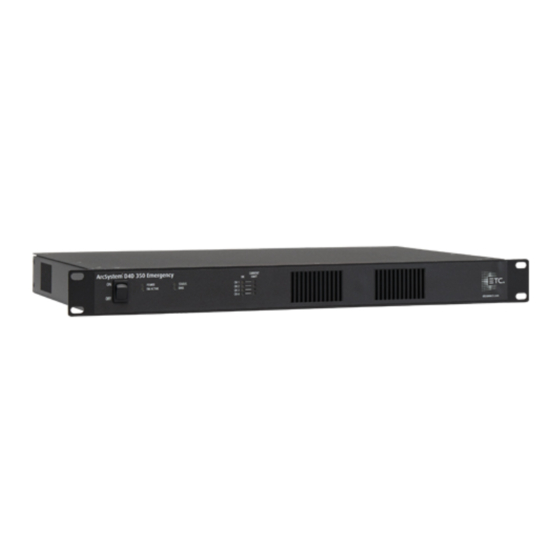
Rack-Mount Emergency Drivers Rack-Mount D4 Emergency Driver 350 Rack-Mount D4 Emergency Driver 700 A Output channel "CH 1" E "DMX In" B Output channel "CH 2" F "DMX Thru" C Output channel "CH 3" G Maintained power input cord (bare end) D Output channel "CH 4" H Normal/Sense power input cord (bare end) D4 Series Drivers Installation Guide... - Page 45 Rack-Mount Emergency Driver Installation WARNING: RISK OF DEATH BY ELECTRIC SHOCK! Before you begin pulling and terminating wire to the ArcSystem Driver enclosure or TX1 Transmitter, make sure the main circuit breaker cabinet or other readily accessible input power disconnect device for the normal power input (and emergency power input when used) is locked out and tagged out.
-
Page 46: D4 Emergency Driver 150 Current Configuration
Switches 2 through 5 are factory set to allow each output to be controlled by an individual DMX address. ETC recommends leaving the DMX channel switches (positions 2 through 5) at their factory settings and using the ArcSystem Configuration Software or RDM settings to control the behavior of each output. -
Page 47: Final Installation And Operation
All ArcSystem luminaires are factory set to provide 100% output level. This allows an electrical contractor to check that all products are properly installed and wired. During system commissioning, the certified ETC technician will remove this setting and configure DMX addresses for normal use. During normal use after commissioning is complete, ArcSystem luminaires will light if the DMX Control level is greater than 0. -
Page 48: Commissioning A Wireless Arcsystem
Initial programming of a wireless ArcSystem requires a USB commissioning tool (ARC-CT), and existing hardware such as a laptop or desk top computer that is connected to ArcSystem. This programming will be carried out by an ETC certified technician at the time of system commissioning and training. -
Page 49: Rdm Values
ArcSystem wireless luminaires ARC-TX1 DMX512 DMX512 DMX512 from lighting console ArcSystem wired DMX luminaires Third party DMX devices Note: By default the TX1 DMX output is disabled. If you require DMX output from the TX1, you must use the ArcSystem comissioning tool software to add DMX fixtures. RDM Values Manufacturer ID: 0x6574 (Electronic Theatre Controls) Model IDs... - Page 50 Parameter RDM PID Value Notes Default is 001. The upper limit for the D4 DMX Start Address 0x00F0 Range = 001 to 512 Series drivers is 508. Default is 2. This parameter sets the number of DMX channels available on a D4 Series driver. Set to 1 sets DMX personality to multi- •...
-
Page 51: Maintenance
WARNING: RISK OF ELECTRIC SHOCK! The light sources in this luminaire are not user-replaceable, and must be replaced only by a qualified technician. Contact ETC Customer Support for assistance. AVERTISSEMENT : RISQUE DE DÉCHARGE ÉLÉCTRIQUE! Les sources lumineuses de ce projecteur ne sont pas remplaçables par l'utilisateur et doivent être remplacées seulement par un technicien qualifié. -
Page 52: Emergency Operation And Test
A can of compressed air or oil-free air from an air compressor set at a low setting can be used to blow through the vent holes and remove dust or other debris. Dust buildup can cause overheating and premature shutdown. All components can be cleaned using compressed, oil-free air as described above or a clean micro-fiber cloth. -
Page 53: Troubleshooting
D4 Driver 700 and D4 Emergency Driver 700 only PSU 1 Fault On: power supply 1 has a fault. Contact ETC Technical Services for assistance. D4 Driver 700 and D4 Emergency Driver 700 only PSU 2 Fault On: power supply 2 has a fault. Contact ETC Technical Services for assistance. -
Page 54: Overload Protection
Overload Protection D4 series drivers have to types of maximum output limit: warning and trip. Contact ETC technical services for assistance with warning and fault conditions. Warning On D4 Driver 350 and 700 models only, the "Channel OK" LED will remain solid on and the Channel Limit LED will light if the current drawn on any channel exceeds the warning limits. -
Page 55: Bridge D4 Series Constant Voltage Driver Output Channels
Bridge D4 Series Constant Voltage Driver Output Channels It is acceptable to bridge multiple output channels together on an ArcSystem D4 Series Constant Voltage Driver, ganging the maximum output allowed into a single combined output channel. See below for examples of the configurations made possible by bridging output channels. Note: A maximum of two output channels can be bridged together on a D4 Driver 700 (standard or emergency model). - Page 56 AVERTISSEMENT : Vous devez utiliser un kit de câblage agréé et fourni par ETC. Ne pontez pas les circuits de sortie avec des fils ou du matériel non agréés. Note: Power wiring should only be installed and terminated by a qualified electrician and should follow standard wiring installation practices.
-
Page 57: Voltage Drop
Consult the manufacturer's documentation for your load to find the minimum voltage required for operation. Voltage drop calculations vary by project and are based on the type, length, and gauge of wire used between the D4 Driver and load. Contact a qualified electrician or ETC technical services for further information. -
Page 58: Output Channel Control Switches
Output Channel Control Switches Each output channel on the D4 Driver is controlled by a switch block (S1–S4, shown below). Switch positions 2–5 are factory set to allow individual control of each output. In order to bridge channels together, you must adjust the positions of switches 2–5. LED 4 LED 3 Switch... - Page 59 Switch Blocks Each of the four switch blocks controls one output channel. Switch block S1 controls the output channel labeled "LED 1" on D4 Driver 150 or "CH 4" • on D4 Driver 350 and 700. Switch block S2 controls the output channel labeled "LED 2" on D4 Driver 150 or "CH 3" •...
- Page 60 Setting Switches 2 Through 5 for Bridged Output Channels Note: Each output channel that you want to bridge must have the same setting for switch positions 2–5 as the other output channels in the bridge. Output channels that are electrically connected (bridged) with different switch settings may have reduced capcacity.
-
Page 61: Example Bridge Configurations
Example Bridge Configurations All Four Output Channels Bridged Bridging four output channels can be done as shown below for control on output channel 1, or on any output channel as long as all four switch blocks (S1–S4) are set the same. The illustration and table below show all four output channels bridged together to form bridged output channel 1. - Page 62 Output Channels Bridged in Pairs Bridging pairs of output channels can be done as shown below for control on output channel 1 and output channel 2, or on any pair of output channels as long as the output channels that are electrically connected (bridged) have the same switch block settings. The illustrations and table below show output channel 1 and output channel 2 bridged to form bridged output channel 1 and output channel 3 and output channel 4 bridged to form bridged output channel 3.
- Page 63 Three Output Channels Bridged Bridging three output channels can be done as shown below for control on output channel 1, or on any channel as long as the three output channels that are electrically connected (bridged) have the same switch block settings. The fourth output channel can be assigned to any of the three remaining channels.
-
Page 64: Bridging Procedure
Bridging Procedure The steps below describe how to bridge output channels on wall-mount and rack-mount D4 Driver models. Wall-mount D4 Driver models have four two-position screw-terminal connections located inside the enclosure. Rack-mount D4 Driver 350 and 700 models have four two-position screw-terminal plugs installed in the back of the enclosure. -
Page 65: Compliance
Compliance For current and complete compliance information, view the product datasheets at etcconnect.com/ArcSystem. FCC Compliance Wireless-capable ArcSystem products comply with Part 15 of the FCC Rules. Operation is subject to the following two conditions: (1) this device may not cause harmful interference, and (2) this device must accept any interference received;... - Page 66 D4 Series Drivers Installation Guide...
- Page 67 Compliance...
- Page 68 Holzkirchen, DE +49 (80 24) 47 00-0 Rome, IT +39 (06) 32 111 683 Hong Kong +852 2799 1220 Paris, FR +33 1 4243 3535 etcconnect.com Support support.etcconnect.com Contact etcconnect.com/contactETC © 2020 ETC Trademark and patent info: etcconnect.com/ip Product information and specifications subject to change. ETC intends this document to be provided in its entirety. 7490M2170 Rev C Released 2020-12...
Need help?
Do you have a question about the ArcSystem Pro D4 Series and is the answer not in the manual?
Questions and answers