Muratec MFX-2500 Field Engineering Manual
Hide thumbs
Also See for MFX-2500:
- Operating instructions manual (208 pages) ,
- User manual (102 pages) ,
- Specifications (1 page)
Table of Contents
Advertisement
Quick Links
Download this manual
See also:
User Manual
Advertisement
Chapters
Table of Contents
Troubleshooting

Related Manuals for Muratec MFX-2500


Summary of Contents for Muratec MFX-2500
- Page 1 MFX-2500 FIELD ENGINEERING MANUAL North American version 1.0 (Febrary. 29 2000) MURATA MACHINERY, LTD COMMUNICATION EQUIPMENT DIV.
-
Page 2: Safety Information
Safety Information Laser Safety This is a digital machine which prints by means of a laser. There is no possibility of danger from the laser, provided the machine is operated according to the instructions in this manual. Since radiation emitted by the laser is completely confined within protective housing, the laser beam cannot escape from the machine during any phase of user operation. - Page 3 The label shown on next page indicates compliance with the CDRH regulations and must be attached to laser products marketed in the United States. CAUTION: Use of controls, adjustments or performance of procedures other than those specified in this manual may result in hazardous radiation exposure. This is a semiconductor laser.
-
Page 4: Laser Safety Label
Muratec MFX-1500E General Description Laser Safety Label A laser safety label is attached to the outside of the machine as shown below. ID Label Laser safety label IC Label Label inside copy machine The following laser safety label will be attached inside the copy machine as shown below. - Page 5 Replace only with the same or equivalent type recommended by the manufacturer. Dispose of used batteries accordingto the manufacturer’s instructions. Muratec does not recommend the independent replacement of this battery. The battery is sold only as a component part of the main control PCB and cannot be purchased separately from Muratec.
-
Page 6: Table Of Contents
Table of Contents Section 1 General Description 1.1 Product Description ..........................1-1 1.2 General specifications ..........................1-2 1.3 Scanning specifications ........................1-5 1.4 Printer specifications..........................1-6 1.5 Memory specifications ..........................1-7 1.6 G3 modem section..........................1-8 1.7 V.34 HDX modem section ........................1-8 1.8 Features and Functions ........................1-9 1.9 Supply Yields ............................1-13 1.10 Option ...............................1-14 Section2 Machine Composition... - Page 7 4.7 Cannot transmit ............................4-3 4.8 Receive Errors ............................4-3 4.9 Will not Auto-Answer ..........................4-4 4.10 Recording paper misfeed........................4-5 4.11 Error Codes ............................4-19 4.12 Service Call Error..........................4-22 4.13 Image Failure............................4-35 Section5 Maintenance & Adjustment........5-1 5.1 Maintenance schedule..........................5-2 5.2 Re/Disassemble..........................5-18 5.3 Adjustment............................5-81 5.3.1 Printer registration (top).......................5-81 5.3.2 Printer registration (side) ......................5-82 5.3.3 FBS registration (top) ........................5-83 5.3.4 FBS registration (side).........................5-84...
-
Page 8: Section 1 General Description
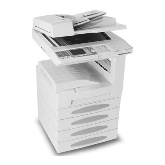
Section 1 General Description 1.1 Product Description The MFX-2500 is Multi-function product with flat bed scanner and Group 3 and V.34 HDX modem facsimile machine. Documents are printed on plain paper using dry electrophotographic printing. 3d right1... -
Page 9: General Specifications
General Description Muratec MFX-2500 1.2 General specifications Item Specifications / Comments Type Multi-function product with flatbed scanner. Group 3 and V.34 HDX console type facsimile with high-speed facsimile transmitter and receiver. Telephone network PSTN (Public Switched Telephone Network) or equivalent. - Page 10 Muratec MFX-2500 General Description Item Specifications / Comments Acceptable recording paper 1st cassette (Multi purpose cassette): size For fax reception: Letter(SEF/LEF), Legal(SEF), Ledger(SEF), Half-letter(SEF/LEF) For copying: Letter(SEF/LEF), Legal(SEF), Ledger(SEF), Half-letter(SEF/LEF), A3(SEF), B4(SEF), A4(SEF/LEF), B5(SEF/LEF), A5(SEF/LEF), A6(SEF), F4(SEF), Postcard(SEF), Custom- sized**, DL(SEF), COM10(SEF),...
- Page 11 Muratec MFX-2500 Item Specifications / Comments Dimensions: 603 (W) 671 (D) 751 (H) mm Weight 67.7 Kg (148.9 lb) Weight includes: a toner bottle, a drum cartridge, Multi purpose cassette, 2nd cassette Keypad layout Body Color Muratec light gray (91-242)
-
Page 12: Scanning Specifications
Muratec MFX-2500 General Description 1.3 Scanning specifications Item Specifications / Comments Scanning method Acceptable document size ADF (Auto Document Feeder) section Document size (Width Length) Single sheet Max: 300 mm(11.8 ) 900 mm(35.4 ) (Tx) 300 mm(11.8 ) 450 mm(17.7 ) (Copy) Min: 120 mm(4.7 ) -
Page 13: Printer Specifications
General Description Muratec MFX-2500 1.4 Printer specifications Item Specifications / Comments Printing resolution Laser diode beam scanning 600 dpi 600 lpi Printing method Dry electrophotographic printer Fusing method Heat roller Printing margin Upper: 4 mm, Lower: 4 mm, Right: 4 mm, Left: 4 mm... -
Page 14: Memory Specifications
Muratec MFX-2500 General Description 1.5 Memory specifications Item Specifications / Comments Document memory 16 MB (Standard) Optional memory upgrade: See the table below. Document stored capacity 1,330 pages Document memory backup (Total memory capacity : Backup time) 16 MB: 60 hours... -
Page 15: G3 Modem Section
General Description Muratec MFX-2500 1.6 G3 modem section Transmission mode V.17 Modulation method 128 Pt. TCM 64 Pt. TCM 32 Pt. TCM 16 Pt. TCM Transmission speed 14400 12000 9600 7200 (bit/s) Modulation speed 2400 2400 2400 2400 (baud) Carrier frequency (Hz) -
Page 16: Features And Functions
Muratec MFX-2500 General Description 1.8 Features and Functions 1.8.1 Dialer Item Specifications / Comments Autodialer 300 total; 78 one-touch, 222 speed dial. (Up to 40 digits per location; 24 characters per location ID) Programmable one-touch. 6 total The programmable one-touch keys simplify complex fax operation. - Page 17 General Description Muratec MFX-2500 1.8.2 Fax Transmitting Item Specifications / Comments Transmit Terminal Identifier Alphanumeric or symbol, up to 22 characters. (TTI) Subscriber ID: Numeric, up to 20 characters 3 patterns of TTI can be registered. Memory transmission Available. Feeder transmission Available.
-
Page 18: Fax Receiving
Muratec MFX-2500 General Description 1.8.3 Fax Receiving Item Specifications / Comments Receive mode Tel ready, Fax ready, Fax/Tel ready, Tel/Fax ready and Ans/Fax ready mode; user selectable. Receive reduction rate Auto: Automatically reduces printouts from 100 % to 25 %. -
Page 19: Other Features
General Description Muratec MFX-2500 1.8.5 Copy Item Specifications / Comments FCOT (First Copy Out Time) Multiple copies Up to 99 Copy reduction and Manual: Reduces/enlarges copies by the 1 % ratio from 400 % to 25 %. enlargement rate Fixed: Select the fixed rates from 154, 129, 121, 77, 64, 50 % Directional magnification Reduces/enlarges copies at different ratios horizontally and vertically. -
Page 20: Supply Yields
Muratec MFX-2500 General Description 1.8.7 Reports Report Description One-touch dial list Prints numbers stored in the one-touch keys. Speed dial list Prints phone numbers stored in speed dial locations. Programmable one-touch Prints numbers stored in programmable one-touch keys. list Group number list Prints groups stored in the autodialer. -
Page 21: Option
General Description Muratec MFX-2500 1.10 Option Item Specifications / Comments Shift tray 2-Bin tray Handset Mark-4 simple type (without numeric keypad) Mechanical page counter 6 digits Memory 8 MB, 24 MB (See the table on page 1-6.) Paper feed unit... -
Page 22: Section2 Machine Composition
Section2 Machine Composition 2.1 Interconnect Block Diagram (Scanner) See next page. -
Page 26: Interconnect Block Diagram (Printer)
2.2 Interconnect Block Diagram (Printer) -
Page 30: Scanning Section
2.3 Scanning Section 2.3.1 ADF Section When a document is placed into the document feeder, Document Sensor 1 (DS1) is activated and you will hear the short beep. The width of document is detected by DB4 and DA3 sensors and length of document is detected by DADFA3 and DADFLEG sensors. - Page 31 2.3.2 FBS section Light reflected from the original passes through three mirrors and a lens to form a reduced image on the CCD Sensor as the Scanner is moved by the Scanner Motor. The CCD sensor converts the light pattern (image data) into an electrical image signal.
- Page 32 2.3.2.1 Exposure Section: Construction and Function 1 Reflector Tape When a book or other bound original is copied, the paper in the area near the binding generally fails to come flush against the glass, so that the copy of these areas is generally too dark. The Reflector Tape reduces this problem by reflecting light from the Exposure Lamp onto these areas of the original.
- Page 33 2.3.2.3 Original Size Detection Timing The copier CPU affirms and resets the readings of the original size at the following timings. Takes size readings: When the BIS sensor is deactivated. Affirms size readings: When the Start key is pressed with the BIS sensor activated or the APS sensor deactuated. Resets size readings: When the APS sensor is deactuated.
- Page 34 2.3.2.4 Mirror Carriage A and Mirror Carriage B Moving Mechanism <Mirror Carriage Ar> During a scan, the Mirror Carriage A projects an even amount of light from the Exposure Lamp onto the entire surface of the original. The light is reflected from the original to the Mirror A of the Mirror Carriage A and then to the Mirror B and Mirror C of the Mirrors Carriage B.
-
Page 35: Recording Section
2.4 Recording Section 2.4.1 Cross-sectional view 1. 2nd Mirror 2. 3rd Mirror 3. Exposure Lamp 4. 1st Mirror 5. Lens 6. CCD Unit 7. Paper Exit Roller 8. Fusing Roller Thermostat (TS1) 9. Fusing Roller Heater Lamp (H1) 10. Paper Exit Sensor (PC3) 11. -
Page 36: Image Processing
2.4.2 Image Processing 1. PC Drum The drum is an aluminum cylinder coated with photosensitive material on which an electrostatic latent image is produced. 2. Drum Charging A scorotron charger employing a comb electrode generates a negative DC charged layer on the surface of the PC Drum. - Page 37 2.4. 3 Drive System A. I/C Motor (M1) Drives the I/C Unit (Drum cartridge). B. Main Motor (M2) Drives the Paper Take-Up Roll, Manual Feed Paper Take-Up Roll, Synchronizing Roller, Image Transfer Roller, and Fusing Unit. 2-16...
- Page 38 2.4.4 Imaging Cartridge (I/C) This machine employs an Imaging Cartridge (“I/C” in this manual) that contains a PC Drum, PC Drum Charge Corona, Developing Unit, and Cleaning Unit as one unit. Toner Supply Port ATDC Sensor (E1) 2-17...
- Page 39 2.4.4.1 I/C Drive Mechanism Drive from the I/C Motor is transmitted via a gear train to the PC Drum and Hopper. PC Drum Driver Gear I/C Motor (M1) Hopper Drive Gear Electrical Component Control Signal PJ16A-3 See block diagram of the printer. 2.4.4.2 Identification and Life of I/C When the Start key is pressed or the Side Cover is opened and closed, the machine determines whether the I/C is new or one which has been used previously.
- Page 40 2.4.5 PC Drum The PC Drum used in this machine is the organic photoconductor (OPC) type. The drum consists of an aluminum base coated with a charge generation layer and a charge transport layer. Handling Precautions Prolonged exposure to light can cause the photoconductor surface of the drum to suffer light fatigue, resulting in a loss of photosensitivity.
-
Page 41: Drum Charging
2.4.6 Drum Charging A scorotron charger system generates a negative DC corona discharge onto the PC Drum surface. The grid mesh ensures uniform charging. The grid voltage (Vg) applied to the grid mesh is controlled by the constant voltage circuitry within the High Voltage Unit. -
Page 42: Erase Lamp
2.4.7 Erase Lamp Any potential remaining on the surface of the PC Drum is neutralized by both light from the Erase Lamp and a DC negative voltage applied by the Charge Neutralizing Sheet. The Charge Neutralizing Sheet applies a negative charge on the surface of the PC Drum which is positively charged by the Image Transfer Roller. - Page 43 2.4.8 PH Section Based on the image data output from the MFB Board, the LD (laser diode) is activated and the corresponding light strikes the surface of the PC Drum. PH Unit 2-22...
- Page 44 2.4.8.1 PH Components 1. Polygon Motor (M10) 2. Cylindrical Lens 3. SOS Mirror 4. Collimator Lens 5. Laser Diode Board (PWB-B) 6. SOS Sensor 7. f- Lens Electrical Component Control Signal PJ8A-3 See block diagram of the printer. 2-23...
- Page 45 2.4.8.2 Laser Emission Timing (SOS Signal) The signal output from the Master Board triggers the firing of the laser. The laser beam travels to the Polygon Mirror, lens, and SOS Mirror to eventually hit the SOS Sensor, which generates an SOS signal. The SOS signal determines the laser emission timing for each line in the main scanning direction.
-
Page 46: Developing Unit
2.4.9 DEVELOPING UNIT The Toner Conveying Rollers mix the toner and carrier particles together and carry the toner/carrier mixture up to the Sleeve/Magnet Roller. The magnetic brush formed on the surface of the roller allows the toner to come into contact with the charges on the surface of the PC Drum, thus forming an electrostatic latent image. - Page 47 2.4.9.1 Sleeve/Magnet Roller This machine employs the MT-HG system with a Sleeve/Magnet Roller having the following magnetic characteristics. Turning of the sleeve surrounding the Magnet Roller ensures that fresh developer from the Developer Mixing Chamber is always being conveyed to the point of development with respect to the PC Drum. : The point of development with the maximum magnetic flux density which ensures that the carrier is firmly held onto the Sleeve Roller when toner is attracted to the latent image.
- Page 48 2.4.9.2 Developing Bias The amount of toner attracted onto the surface of the PC Drum is controlled by varying the developing bias voltage. As the PC Drum deteriorates and its photoconductive layer begins to wear, it becomes more sensitive to the increase in the amount of toner.
-
Page 49: Atdc Sensor
2.4.9.3 ATDC Sensor The ATDC Sensor automatic adjustment is made when a new I/C is installed in the machine. Toner replenishing control is thereafter controlled as detailed in the following. 1. ATDC Sensor Automatic Adjustment The ATDC Sensor is automatically adjusted when a new I/C is loaded in the machine. During this sequence, the machine reads the sensor output value and sets it as the reference. - Page 50 2.4.9.4 Sub Hopper Toner Replenishing Mechanism Toner is replenished from the Sub Hopper to the Developing Unit by turning the Sub Hopper Toner Replenishing Motor for the period of time controlled by the ATDC output voltage (T/C). Sub Hopper Sub Hopper Toner Replenishing Motor (M7) Electrical Component Control Signal PJ11A-8A...
-
Page 51: Sub Hopper Toner Empty Detecting Mechanism
2.4.9.5 Sub Hopper Toner Empty Detecting Mechanism A toner-empty condition in the Sub Hopper is detected by the Magnet Lever that moves up and down as the Sub Hopper Toner Agitating Lever turns and actuates and de-actuates the Sub Hopper Toner Empty Switch. - Page 52 2.4.9.6 Main Hopper Toner Replenishing Mechanism When a toner-empty condition in the Sub Hopper is detected, the Main Hopper Toner Replenishing Motor is energized to turn the Toner Bottle, thereby supplying toner from the Main Hopper to the Sub Hopper. The Toner Bottle Home Position Sensor mounted on the coupling ensures that the Toner Supply Port in the Toner Bottle is positioned at the top whenever the bottle is stopped.
- Page 53 2.4.9.7 I/C Cooling Fan Motor The I/C Cooling Fan Motor prevents the temperature inside the machine (around the entire I/C) from rising inordinately. I/C Cooling Fan Motor (M9) Electrical Component Control Signal PJ18A-10 DC24V See block diagram of the printer. 2.4.9.8 Ozone Fan Motor Ozone produced by the PC Drum Charge Corona is absorbed by the Ozone Filter from the air being drawn out of the machine by the Ozone Fan Motor.
- Page 54 2.4.10 PAPER TAKE-UP/FEED SECTION Note: For the details of the paper feed cassette (500-Sheet Cassette), see the Section 6 on this service manual. This machine employs the Multi-Purpose (MP) Cassette whose capacity is about 250 sheets (about 20 sheets for special paper). Paper Size Detecting Board (PWB-I) Paper Take-up Roll Tailing Edge Stop...
- Page 55 2.4.10.2 MP Cassette-in-Position Detection When the MP Cassette is slid into the machine, the light blocking plate located in the rear of the cassette blocks the Cassette Set Sensor and the machine determines that the MP Cassette has been slid into position.
- Page 56 2.4.10.3 MP Cassette Paper Empty Detection Two sensors are used in this machine: the Paper Empty Sensor detects a paper-empty condition, while the Paper Near-Empty Sensor detects a paper near-empty condition. Paper Near-Empty Detection: A paper near-empty condition is detected as the paper is consumed and when the Near-Empty Lever lowers to eventually block the sensor (L).
- Page 57 2.4.10.4 MP Cassette Paper Size Detection The Paper Size Detecting Board detects the length of the paper (FD). A lever is connected to the Trailing Edge Stop of the cassette and, as the stop is slid to the size of the paper loaded in the cassette, the lever is moved to turn ON and OFF the size detecting switches mounted on the machine side.
- Page 58 2.4.10.5 Paper Take-Up Mechanism Drive from the Main Motor is transmitted to the Paper Take-Up Clutch (spring clutch) and, by energizing the Paper Take-Up Solenoid, the Paper Take-Up Roll is turned. The paper separating mechanism employs a Paper Separator Pad. Paper Separator Pad 2.4.10.6 Manual Bypass Tray (Option) 1.
- Page 59 2. Manual Feed Paper Take-Up Detection The Manual Feed Paper Take-Up Sensor detects a sheet of paper that is fed via the Manual Bypass Tray. The size and type of the paper for manual feed are set on the control panel. Electrical Component Control Signal Unblocked...
-
Page 60: Synchronizing Rollers
2.4.11 SYNCHRONIZING ROLLERS The Synchronizing Rollers of this machine are located inside the Right Door. They are easily accessible for misfeed clearing by just opening the Right Door. 2.4.11.1 Synchronizing Roller Drive Mechanism/Control The Synchronizing Rollers are turned by the drive from the Main Motor transmitted to the Synchronizing Clutch. -
Page 61: Paper Dust Remover
2.4.11.2 Paper Dust Remover The Paper Dust Remover is installed so that it makes contact with the Left Synchronizing Roller. It is intended for preventing paper dust from sticking to the surface of the PC Drum. As the roller turns in contact with the Paper Dust Remover, triboelectric charging occurs, which attracts paper dust from the paper that passes between the two rollers and the dust is, in turn, transferred onto the Paper Dust Remover. -
Page 62: Image Transfer And Paper Separation
2.4.12 IMAGE TRANSFER AND PAPER SEPARATION Image Transfer This machine employs an Image Transfer Roller to transfer the image to the paper. The High Voltage Unit applies an image transfer current to this roller. To ensure that image transfer efficiency is stabilized, the image transfer current is automatically varied according to the paper size, paper type, and the B/W ratio of the original. -
Page 63: Pc Drum Paper Separator Fingers
2.4.13 PC DRUM PAPER SEPARATOR FINGERS The three PC Drum Paper Separator Fingers fitted to the I/C mechanically separate paper from the surface of the PC Drum to ensure good and positive paper separation. PC Drum Paper Separator Fingers PC Drum PC Drum Protective Shutter Paper Path Center 8.5 cm... -
Page 64: Pc Drum Cleaning
2.4.14 PC DRUM CLEANING This machine employs a spent toner recycling mechanism. The Cleaning Blade which is held pressed against the surface of the PC Drum scrapes residual toner off the surface. The waste toner is conveyed by Spent Toner Feed Roller 1 and 2 to the Spent Toner Recycling Duct and eventually back to the Developer Mixing Chamber. -
Page 65: Fusing Unit
2.4.15 FUSING UNIT The paper, to which the developed image is yet to be fixed, is fed through heated Left and Right Fusing Rollers. The heat and pressure applied at this time fixes the image permanently to the paper. 1. Paper Exit Roller 2. - Page 66 2.4.15.1 Drive Mechanism Drive from the Main Motor is transmitted via a gear train to the Right Fusing Roller. Right Fusing Roller Paper Exit Roller Main Motor (M2) Electrical Component Control Signal PJ16A-1 See block diagram of printer. 2.4.15.2 Fusing Rollers Pressure Mechanism To ensure that there is a certain width of area of contact between the Left and Right Fusing Rollers, pressure springs are installed.
- Page 67 2.4.15.3 Fusing Temperature Control The Fusing Roller Heater Lamp inside the Left Fusing Roller provides the following temperature control. - Temperature Control During Standby State - Approx. Approx. 5 min. 1 min. Mode 1 Mode 2 Mode 3 Warm-Up Completed (200˚C) - Temperature Control During a Copy Cycle - Special paper...
- Page 68 <Temperature Control by Mode> The mode that is initiated following the completion of a warm-up cycle varies as detailed below depending on the machine condition and the Fusing Roller temperature at the restart of temperature control. Fusing Roller Temperature Machine Condition Less than 100°C 100°C or higher Power is turned ON.
-
Page 69: Paper Exit Unit
2.4.16 PAPER EXIT UNIT The Paper Exit Roller feeds the paper, to which the developed image has been fixed, out of the machine. The Charge Neutralizing Brush touches the surface of the sheet of paper being fed out of the Fusing Unit to neutralize any static charge left on it. -
Page 70: Fusing Cooling Fan Motor
2.4.17 FUSING COOLING FAN MOTOR The Fusing Cooling Fan Motor located in the Right Door prevents the temperature of the Fusing Unit Cover and the area above the I/C from rising inordinately. The motor also draws the paper after it has been separated from the PC Drum onto the transport guide to ensure that it is stably and smoothly fed into the Fusing Unit. -
Page 71: Power Unit Cooling Fan Motor
2.4.18 POWER UNIT COOLING FAN MOTOR The Power Unit Cooling Fan Motor prevents the temperature at the Power Supply Unit and the Polygon Motor in the PH from rising inordinately. Power Unit Cooling Fan Motor (M4) Power Supply Unit 1 (PS1) Master Board (PWB-A) Electrical While Main Motor is Turning... -
Page 72: Section3 Software Adjustment
Section3 Software adjustment 3.1 Field Service Program Modes The machine feature maintenance modes for machine adjustment. Each mode is listed below along with the command used to activate the mode and a brief functional description. Set or Clear Machine Parameters..................MENU, *, 0 Used to set or clear machine parameters. -
Page 73: Machine Parameter Adjustment
3.2 Machine Parameter Adjustment 3.2.1 Setting the Machine Parameters These switches are used to program internal machine parameters. The primary back up battery maintains these settings if power is lost. 1. From standby, press MENU, *, 0. 2. Select the desired parameter by cursor key or by pressing a one-touch key plus a number on the keypad. - Page 74 Machine Parameter A:0 Initial Switch Adjust Usage/Comments Setting The country code enables the ROM to output the correct programming information for the respective country. Country code Machine Parameter A:1 Initial Switch Adjust Usage/Comments Setting Factory use only Factory use only Factory use only Factory use only Output attenuation...
- Page 75 Machine Parameter A:2 Initial Switch Adjust Usage/Comments Setting Factory use only Factory use only Factory use only Factory use only DTMF output level See table below. attenuation Machine Parameter A:2 _ DTMF output level attenuation — (Factory default is -15 dB) Switch 3 Switch 2 Switch 1...
- Page 76 Å Note: These values 00000000 0 mm Standard are factory set and should not be adjusted unless 10001000 -1.69 mm instructed by a Muratec technical representative. 10010000 -3.39 mm -25 steps 10011001 -5.29 mm Machine Parameter B:1 Initial Switch Adjust...
- Page 77 40 steps 00101000 +6.77 mm Note: These values are factory set and should not be adjusted unless 30 steps 00011110 +5.08 mm instructed by a Muratec 20 steps 00010100 +3.39 mm technical representative. 10 steps 00001010 +1.69 mm 3steps 00000011 +0.51 mm...
- Page 78 40 steps 00101000 +6.77 mm Note: These values are factory set and should not be adjusted unless 30 steps 00011110 +5.08 mm instructed by a Muratec 20 steps 00010100 +3.39 mm technical representative. 10 steps 00001010 +1.69 mm 3steps 00000011 +0.51 mm...
- Page 79 Machine Parameter B:6 Initial Switch Adjust Usage/Comments Setting Adjustment of the scanning Switch 76543210 Settings stretching and squeezing for FBS. 00001111 +1.5 % (Horizontal) 00001000 +0.8 % The plus setting stretch the image data and the minus 00000100 +0.4 % setting squeeze it.
- Page 80 +0.14 mm Å are factory set and should 00000000 5 mm Initial setting not be adjusted unless -1 step 10000001 -0.14 mm instructed by a Muratec technical representative. -2 steps 10000010 -0.28 mm -4 steps 10000100 -0.56 mm -8 steps 10001000 -1.13 mm...
- Page 81 Note: These values 30 steps 00011110 +4.22 mm are factory set and should not be adjusted unless 20 steps 00010100 +2.82 mm instructed by a Muratec technical representative. 10 steps 00001010 +1.41 mm 3 steps 00000011 +0.42 mm 2 steps 00000010 +0.28 mm...
- Page 82 Machine Parameter D:1 Initial Switch Adjust Usage/Comments Setting Scanning contrast level Switch 76543210 adjustment in fine resolution. 01111111 Darkest setting 00001000 Å 00000000 Initial setting 10001000 11111111 Lightest setting Machine Parameter D:2 Initial Switch Adjust Usage/Comments Setting Scanning contrast level Switch 76543210 adjustment in super-fine 01111111...
- Page 83 Machine Parameter D:7 Initial Switch Adjust Usage/Comments Setting Scanning contrast level Switch 76543210 adjustment for copy 00111111 Darkest setting resolution. 00000011 +3 Copy mode: Photo 00000010 +2 Contrast: Auto, 600 dpi 00000001 +1 Å 00000000 Initial setting 11111111 -1 11111110 -2 11111101 -3 11000000 Lightest setting...
- Page 84 Machine Parameter J:1 Initial Switch Adjust Usage/Comments Setting Factory use only When set to “1”, the cassette is not available in rotate fax reception. Factory use only Able to use the 1st cassette Note: This setting does not affect the normal fax in rotate fax reception.
- Page 85 Machine Parameter K:0 Initial Switch Adjust Usage/Comments Setting Printer registration Switch 76543210 Settings adjustment (Horizontal) at the 2nd cassette in normal 127 steps 01111111 +12.7 mm printing. 32 steps 00100000 +3.2 mm Adjusts the start point to print. 16 steps 00010000 +1.6 mm The plus setting increase the...
- Page 86 Machine Parameter K:2 Initial Switch Adjust Usage/Comments Setting Printer registration Switch 76543210 Settings adjustment (Horizontal) at the 4th cassette in normal 127 steps 01111111 +12.7 mm printing. 32 steps 00100000 +3.2 mm Adjusts the start point to print. 16 steps 00010000 +1.6 mm The plus setting increase the...
- Page 87 Machine Parameter K:4 Initial Switch Adjust Usage/Comments Setting Printer registration Switch 76543210 Settings adjustment (Horizontal) at the LCC in normal printing. 127 steps 01111111 +12.7 mm Adjusts the start point to 32 steps 00100000 +3.2 mm print. 16 steps 00010000 +1.6 mm The plus setting increase the left margin and the minus...
- Page 88 Machine Parameter K:6 Initial Switch Adjust Usage/Comments Setting Printer registration Switch 76543210 Settings adjustment (Horizontal) at the Bypass tray in normal 127 steps 01111111 +12.7 mm printing. 32 steps 00100000 +3.2 mm Adjusts the start point to print. 16 steps 00010000 +1.6 mm The plus setting increase the...
- Page 89 Machine Parameter L:0 Initial Switch Adjust Usage/Comments Setting Printer registration Switch 76543210 Settings adjustment (Horizontal) at the 2nd cassette in rotate 127 steps 01111111 +12.7 mm printing. 32 steps 00100000 +3.2 mm Adjusts the start point to print. 16 steps 00010000 +1.6 mm The plus setting increase the...
- Page 90 Machine Parameter L:2 Initial Switch Adjust Usage/Comments Setting Printer registration Switch 76543210 Settings adjustment (Horizontal) at the 4th cassette in rotate printing. 127 steps 01111111 +12.7 mm Adjusts the start point to 32 steps 00100000 +3.2 mm print. 16 steps 00010000 +1.6 mm The plus setting increase the...
- Page 91 Machine Parameter L:4 Initial Switch Adjust Usage/Comments Setting Printer registration Switch 76543210 Settings adjustment (Horizontal) at the LCC in rotate printing. 127 steps 01111111 +12.7 mm Adjusts the start point to 32 steps 00100000 +3.2 mm print. 16 steps 00010000 +1.6 mm The plus setting increase the left margin and the minus...
- Page 92 Machine Parameter L:6 Initial Switch Adjust Usage/Comments Setting Printer registration Switch 76543210 Settings adjustment (Horizontal) at the Bypass tray in rotate printing. 127 steps 01111111 +12.7 mm Adjusts the start point to 32 steps 00100000 +3.2 mm print. 16 steps 00010000 +1.6 mm The plus setting increase the...
- Page 93 Machine Parameter M:0 Initial Switch Adjust Usage/Comments Setting Printer registration Switch 76543210 Settings adjustment (Horizontal) at the 2nd cassette in normal 127 steps 01111111 +12.7 mm printing. 32 steps 00100000 +3.2 mm Adjusts the end point to print. 16 steps 00010000 +1.6 mm The plus setting increase the...
- Page 94 Machine Parameter M:2 Initial Switch Adjust Usage/Comments Setting Printer registration Switch 76543210 Settings adjustment (Horizontal) at the 4th cassette in normal 127 steps 01111111 +12.7 mm printing. 32 steps 00100000 +3.2 mm Adjusts the end point to print. 16 steps 00010000 +1.6 mm The plus setting increase the...
- Page 95 Machine Parameter M:4 Initial Switch Adjust Usage/Comments Setting Printer registration Switch 76543210 Settings adjustment (Horizontal) at the Large Capacity Cassette in 127 steps 01111111 +12.7 mm normal printing. 32 steps 00100000 +3.2 mm Adjusts the end point to print. 16 steps 00010000 +1.6 mm The plus setting increase the...
- Page 96 Machine Parameter M:6 Initial Switch Adjust Usage/Comments Setting Printer registration Switch 76543210 Settings adjustment (Horizontal) at the Bypass tray in normal 127 steps 01111111 +12.7 mm printing. 32 steps 00100000 +3.2 mm Adjusts the end point to print. 16 steps 00010000 +1.6 mm The plus setting increase the...
- Page 97 Machine Parameter N:0 Initial Switch Adjust Usage/Comments Setting Printer registration Switch 76543210 Settings adjustment (Horizontal) at the 2nd cassette in rotate 127 steps 01111111 +12.7 mm printing. 32 steps 00100000 +3.2 mm Adjusts the end point to print. 16 steps 00010000 +1.6 mm The plus setting increase the...
- Page 98 Machine Parameter N:2 Initial Switch Adjust Usage/Comments Setting Printer registration Switch 76543210 Settings adjustment (Horizontal) at the 4th cassette in rotate printing. 127 steps 01111111 +12.7 mm Adjusts the end point to print. 32 steps 00100000 +3.2 mm The plus setting increase the 16 steps 00010000 +1.6 mm...
- Page 99 Machine Parameter N:4 Initial Switch Adjust Usage/Comments Setting Printer registration Switch 76543210 Settings adjustment (Horizontal) at the Large Capacity Cassette in 127 steps 01111111 +12.7 mm rotate printing. 32 steps 00100000 +3.2 mm Adjusts the end point to print. 16 steps 00010000 +1.6 mm The plus setting increase the...
- Page 100 Machine Parameter N:6 Initial Switch Adjust Usage/Comments Setting Printer registration Switch 76543210 Settings adjustment (Horizontal) at the Bypass tray in rotate printing. 127 steps 01111111 +12.7 mm Adjusts the end point to print. 32 steps 00100000 +3.2 mm The plus setting increase the 16 steps 00010000 +1.6 mm...
- Page 101 Machine Parameter O:0 Initial Switch Adjust Usage/Comments Setting Printer registration Switch 76543210 Settings adjustment. 127 steps 01111111 +12.7 mm Adjusts the left margin at the 2nd cassette in normal 32 steps 00100000 +3.2 mm printing. 16 steps 00010000 +1.6 mm The plus setting increase the left margin and the minus 8 steps...
- Page 102 Machine Parameter O:2 Initial Switch Adjust Usage/Comments Setting Printer registration Switch 76543210 Settings adjustment. 127 steps 01111111 +12.7 mm Adjusts the left margin at the 4th cassette in normal 32 steps 00100000 +3.2 mm printing. 16 steps 00010000 +1.6 mm The plus setting increase the left margin and the minus 8 steps...
- Page 103 Machine Parameter O:4 Initial Switch Adjust Usage/Comments Setting Printer registration Switch 76543210 Settings adjustment. 127 steps 01111111 +12.7 mm Adjusts the left margin at the Large Capacity Cassette in 32 steps 00100000 +3.2 mm normal printing. 16 steps 00010000 +1.6 mm The plus setting increase the left margin and the minus 8 steps...
- Page 104 Machine Parameter O:6 Initial Switch Adjust Usage/Comments Setting Printer registration Switch 76543210 Settings adjustment. 127 steps 01111111 +12.7 mm Adjusts the left margin at the Bypass tray in normal 32 steps 00100000 +3.2 mm printing. 16 steps 00010000 +1.6 mm The plus setting increase the left margin and the minus 8 steps...
- Page 105 Machine Parameter P:0 Initial Switch Adjust Usage/Comments Setting Printer registration Switch 76543210 Settings adjustment. 127 steps 01111111 +12.7 mm Adjusts the left margin at the 2nd cassette in rotate 32 steps 00100000 +3.2 mm printing. 16 steps 00010000 +1.6 mm The plus setting increase the left margin and the minus 8 steps...
- Page 106 Machine Parameter P:2 Initial Switch Adjust Usage/Comments Setting Printer registration Switch 76543210 Settings adjustment. 127 steps 01111111 +12.7 mm Adjusts the left margin at the 4th cassette in rotate printing. 32 steps 00100000 +3.2 mm The plus setting increase the 16 steps 00010000 +1.6 mm...
- Page 107 Machine Parameter P:4 Initial Switch Adjust Usage/Comments Setting Printer registration Switch 76543210 Settings adjustment. 127 steps 01111111 +12.7 mm Adjusts the left margin at the Large Capacity Cassette in 32 steps 00100000 +3.2 mm rotate printing. 16 steps 00010000 +1.6 mm The plus setting increase the left margin and the minus 8 steps...
- Page 108 Machine Parameter P:6 Initial Switch Adjust Usage/Comments Setting Printer registration Switch 76543210 Settings adjustment. 127 steps 01111111 +12.7 mm Adjusts the left margin at the Bypass tray in rotate printing. 32 steps 00100000 +3.2 mm The plus setting increase the 16 steps 00010000 +1.6 mm...
- Page 109 Machine Parameter Q:0 Initial Switch Adjust Usage/Comments Setting Printer registration Switch 76543210 Settings adjustment. 127 steps 01111111 +12.7 mm Adjusts the right margin at the 2nd cassette in normal 32 steps 00100000 +3.2 mm printing. 16 steps 00010000 +1.6 mm The plus setting decrease the right margin and the minus 8 steps...
- Page 110 Machine Parameter Q:2 Initial Switch Adjust Usage/Comments Setting Printer registration Switch 76543210 Settings adjustment. 127 steps 01111111 +12.7 mm Adjusts the right margin at the 4th cassette in normal 32 steps 00100000 +3.2 mm printing. 16 steps 00010000 +1.6 mm The plus setting decrease the right margin and the minus 8 steps...
- Page 111 Machine Parameter Q:4 Initial Switch Adjust Usage/Comments Setting Printer registration Switch 76543210 Settings adjustment. 127 steps 01111111 +12.7 mm Adjusts the right margin at the Large Capacity Cassette 32 steps 00100000 +3.2 mm in normal printing. 16 steps 00010000 +1.6 mm The plus setting decrease the right margin and the minus 8 steps...
- Page 112 Machine Parameter Q:6 Initial Switch Adjust Usage/Comments Setting Printer registration Switch 76543210 Settings adjustment. 127 steps 01111111 +12.7 mm Adjusts the right margin at the Bypass tray in normal 32 steps 00100000 +3.2 mm printing. 16 steps 00010000 +1.6 mm The plus setting decrease the right margin and the minus 8 steps...
- Page 113 Machine Parameter R:0 Initial Switch Adjust Usage/Comments Setting Printer registration Switch 76543210 Settings adjustment. 127 steps 01111111 +12.7 mm Adjusts the right margin at the 2nd cassette in rotate 32 steps 00100000 +3.2 mm printing. 16 steps 00010000 +1.6 mm The plus setting decrease the right margin and the minus 8 steps...
- Page 114 Machine Parameter R:2 Initial Switch Adjust Usage/Comments Setting Printer registration Switch 76543210 Settings adjustment. 127 steps 01111111 +12.7 mm Adjusts the right margin at the 4th cassette in rotate 32 steps 00100000 +3.2 mm printing. 16 steps 00010000 +1.6 mm The plus setting decrease the right margin and the minus 8 steps...
- Page 115 Machine Parameter R:4 Initial Switch Adjust Usage/Comments Setting Printer registration Switch 76543210 Settings adjustment. 127 steps 01111111 +12.7 mm Adjusts the right margin at the Large Capacity Cassette 32 steps 00100000 +3.2 mm in rotate printing. 16 steps 00010000 +1.6 mm The plus setting decrease the right margin and the minus 8 steps...
- Page 116 Machine Parameter R:6 Initial Switch Adjust Usage/Comments Setting Printer registration Switch 76543210 Settings adjustment. 127 steps 01111111 +12.7 mm Adjusts the right margin at the Bypass tray in rotate 32 steps 00100000 +3.2 mm printing. 16 steps 00010000 +1.6 mm The plus setting decrease the right margin and the minus 8 steps...
- Page 117 Machine Parameter S:0 Initial Switch Adjust Usage/Comments Setting Printer registration Switch 76543210 Settings adjustment (Vertical) at the 2nd cassette in normal 127 steps 01111111 +12.7 mm printing. 32 steps 00100000 +3.2 mm Adjusts the start point to print. 16 steps 00010000 +1.6 mm The plus setting increase the...
- Page 118 Machine Parameter S:2 Initial Switch Adjust Usage/Comments Setting Printer registration Switch 76543210 Settings adjustment (Vertical) at the 4th cassette in normal 127 steps 01111111 +12.7 mm printing. 32 steps 00100000 +3.2 mm Adjusts the start point to print. 16 steps 00010000 +1.6 mm The plus setting increase the...
- Page 119 Machine Parameter S:4 Initial Switch Adjust Usage/Comments Setting Printer registration Switch 76543210 Settings adjustment (Vertical) at the LCC in normal printing. 127 steps 01111111 +12.7 mm Adjusts the start point to 32 steps 00100000 +3.2 mm print. 16 steps 00010000 +1.6 mm The plus setting increase the top margin and the minus...
- Page 120 Machine Parameter S:6 Initial Switch Adjust Usage/Comments Setting Printer registration Switch 76543210 Settings adjustment (Vertical) at the Bypass tray in normal 127 steps 01111111 +12.7 mm printing. 32 steps 00100000 +3.2 mm Adjusts the start point to print. 16 steps 00010000 +1.6 mm The plus setting increase the...
- Page 121 Machine Parameter T:0 Initial Switch Adjust Usage/Comments Setting Printer registration Switch 76543210 Settings adjustment (Vertical) at the 2nd cassette in rotate 127 steps 01111111 +12.7 mm printing. 32 steps 00100000 +3.2 mm Adjusts the start point to print. 16 steps 00010000 +1.6 mm The plus setting increase the...
- Page 122 Machine Parameter T:2 Initial Switch Adjust Usage/Comments Setting Printer registration Switch 76543210 Settings adjustment (Vertical) at the 4th cassette in rotate printing. 127 steps 01111111 +12.7 mm Adjusts the start point to 32 steps 00100000 +3.2 mm print. 16 steps 00010000 +1.6 mm The plus setting increase the...
- Page 123 Machine Parameter T:4 Initial Switch Adjust Usage/Comments Setting Printer registration Switch 76543210 Settings adjustment (Vertical) at the LCC in rotate printing. 127 steps 01111111 +12.7 mm Adjusts the start point to 32 steps 00100000 +3.2 mm print. 16 steps 00010000 +1.6 mm The plus setting increase the top margin and the minus...
- Page 124 Machine Parameter T:6 Initial Switch Adjust Usage/Comments Setting Printer registration Switch 76543210 Settings adjustment (Vertical) at the Bypass tray in rotate printing. 127 steps 01111111 +12.7 mm Adjusts the start point to 32 steps 00100000 +3.2 mm print. 16 steps 00010000 +1.6 mm The plus setting increase the...
- Page 125 Machine Parameter U:0 Initial Switch Adjust Usage/Comments Setting Printer registration Switch 76543210 Settings adjustment (Vertical) at the 2nd cassette in normal 127 steps 01111111 +12.7 mm printing. 32 steps 00100000 +3.2 mm Adjusts the end point to print. 16 steps 00010000 +1.6 mm The plus setting increase the...
- Page 126 Machine Parameter U:2 Initial Switch Adjust Usage/Comments Setting Printer registration Switch 76543210 Settings adjustment (Vertical) at the 4th cassette in normal 127 steps 01111111 +12.7 mm printing. 32 steps 00100000 +3.2 mm Adjusts the end point to print. 16 steps 00010000 +1.6 mm The plus setting increase the...
- Page 127 Machine Parameter U:4 Initial Switch Adjust Usage/Comments Setting Printer registration Switch 76543210 Settings adjustment (Vertical) at the Large Capacity Cassette in 127 steps 01111111 +12.7 mm normal printing. 32 steps 00100000 +3.2 mm Adjusts the end point to print. 16 steps 00010000 +1.6 mm The plus setting increase the...
- Page 128 Machine Parameter U:6 Initial Switch Adjust Usage/Comments Setting Printer registration Switch 76543210 Settings adjustment (Vertical) at the Bypass tray in normal 127 steps 01111111 +12.7 mm printing. 32 steps 00100000 +3.2 mm Adjusts the end point to print. 16 steps 00010000 +1.6 mm The plus setting increase the...
- Page 129 Machine Parameter V:0 Initial Switch Adjust Usage/Comments Setting Printer registration Switch 76543210 Settings adjustment (Vertical) at the 2nd cassette in rotate 127 steps 01111111 +12.7 mm printing. 32 steps 00100000 +3.2 mm Adjusts the end point to print. 16 steps 00010000 +1.6 mm The plus setting increase the...
- Page 130 Machine Parameter V:2 Initial Switch Adjust Usage/Comments Setting Printer registration Switch 76543210 Settings adjustment (Vertical) at the 4th cassette in rotate printing. 127 steps 01111111 +12.7 mm Adjusts the end point to print. 32 steps 00100000 +3.2 mm The plus setting increase the 16 steps 00010000 +1.6 mm...
- Page 131 Machine Parameter V:4 Initial Switch Adjust Usage/Comments Setting Printer registration Switch 76543210 Settings adjustment (Vertical) at the Large Capacity Cassette in 127 steps 01111111 +12.7 mm rotate printing. 32 steps 00100000 +3.2 mm Adjusts the end point to print. 16 steps 00010000 +1.6 mm The plus setting increase the...
- Page 132 Machine Parameter V:6 Initial Switch Adjust Usage/Comments Setting Printer registration Switch 76543210 Settings adjustment (Vertical) at the Bypass tray in rotate printing. 127 steps 01111111 +12.7 mm Adjusts the end point to print. 32 steps 00100000 +3.2 mm The plus setting increase the 16 steps 00010000 +1.6 mm...
- Page 133 Machine Parameter W:0 Initial Switch Adjust Usage/Comments Setting Printer registration Switch 76543210 Settings adjustment. 127 steps 01111111 +12.7 mm Adjusts the top margin at the 2nd cassette in normal 32 steps 00100000 +3.2 mm printing. 16 steps 00010000 +1.6 mm The plus setting increase the top margin and the minus 8 steps...
- Page 134 Machine Parameter W:2 Initial Switch Adjust Usage/Comments Setting Printer registration Switch 76543210 Settings adjustment. 127 steps 01111111 +12.7 mm Adjusts the top margin at the 4th cassette in normal 32 steps 00100000 +3.2 mm printing. 16 steps 00010000 +1.6 mm The plus setting increase the top margin and the minus 8 steps...
- Page 135 Machine Parameter W:4 Initial Switch Adjust Usage/Comments Setting Printer registration Switch 76543210 Settings adjustment. 127 steps 01111111 +12.7 mm Adjusts the top margin at the Large Capacity Cassette in 32 steps 00100000 +3.2 mm normal printing. 16 steps 00010000 +1.6 mm The plus setting increase the top margin and the minus 8 steps...
- Page 136 Machine Parameter W:6 Initial Switch Adjust Usage/Comments Setting Printer registration Switch 76543210 Settings adjustment. 127 steps 01111111 +12.7 mm Adjusts the top margin at the Bypass tray in normal 32 steps 00100000 +3.2 mm printing. 16 steps 00010000 +1.6 mm The plus setting increase the top margin and the minus 8 steps...
- Page 137 Machine Parameter X:0 Initial Switch Adjust Usage/Comments Setting Printer registration Switch 76543210 Settings adjustment. 127 steps 01111111 +12.7 mm Adjusts the top margin at the 2nd cassette in rotate 32 steps 00100000 +3.2 mm printing. 16 steps 00010000 +1.6 mm The plus setting increase the top margin and the minus 8 steps...
- Page 138 Machine Parameter X:2 Initial Switch Adjust Usage/Comments Setting Printer registration Switch 76543210 Settings adjustment. 127 steps 01111111 +12.7 mm Adjusts the top margin at the 4th cassette in rotate printing. 32 steps 00100000 +3.2 mm The plus setting increase the 16 steps 00010000 +1.6 mm...
- Page 139 Machine Parameter X:4 Initial Switch Adjust Usage/Comments Setting Printer registration Switch 76543210 Settings adjustment. 127 steps 01111111 +12.7 mm Adjusts the top margin at the Large Capacity Cassette in 32 steps 00100000 +3.2 mm rotate printing. 16 steps 00010000 +1.6 mm The plus setting increase the top margin and the minus 8 steps...
- Page 140 Machine Parameter X:6 Initial Switch Adjust Usage/Comments Setting Printer registration Switch 76543210 Settings adjustment. 127 steps 01111111 +12.7 mm Adjusts the top margin at the Bypass tray in rotate printing. 32 steps 00100000 +3.2 mm The plus setting increase the 16 steps 00010000 +1.6 mm...
- Page 141 Machine Parameter Y:0 Initial Switch Adjust Usage/Comments Setting Printer registration Switch 76543210 Settings adjustment. 127 steps 01111111 +12.7 mm Adjusts the bottom margin at the 2nd cassette in normal 32 steps 00100000 +3.2 mm printing. 16 steps 00010000 +1.6 mm The plus setting decrease the bottom margin and the minus 8 steps...
- Page 142 Machine Parameter Y:2 Initial Switch Adjust Usage/Comments Setting Printer registration Switch 76543210 Settings adjustment. 127 steps 01111111 +12.7 mm Adjusts the bottom margin at the 4th cassette in normal 32 steps 00100000 +3.2 mm printing. 16 steps 00010000 +1.6 mm The plus setting decrease the bottom margin and the minus 8 steps...
- Page 143 Machine Parameter Y:4 Initial Switch Adjust Usage/Comments Setting Printer registration Switch 76543210 Settings adjustment. 127 steps 01111111 +12.7 mm Adjusts the bottom margin at the Large Capacity Cassette 32 steps 00100000 +3.2 mm in normal printing. 16 steps 00010000 +1.6 mm The plus setting decrease the bottom margin and the minus 8 steps...
- Page 144 Machine Parameter Y:6 Initial Switch Adjust Usage/Comments Setting Printer registration Switch 76543210 Settings adjustment. 127 steps 01111111 +12.7 mm Adjusts the bottom margin at the Bypass tray in normal 32 steps 00100000 +3.2 mm printing. 16 steps 00010000 +1.6 mm The plus setting decrease the bottom margin and the minus 8 steps...
- Page 145 Machine Parameter Z:0 Initial Switch Adjust Usage/Comments Setting Printer registration Switch 76543210 Settings adjustment. 127 steps 01111111 +12.7 mm Adjusts the bottom margin at the 2nd cassette in rotate 32 steps 00100000 +3.2 mm printing. 16 steps 00010000 +1.6 mm The plus setting decrease the bottom margin and the minus 8 steps...
- Page 146 Machine Parameter Z:2 Initial Switch Adjust Usage/Comments Setting Printer registration Switch 76543210 Settings adjustment. 127 steps 01111111 +12.7 mm Adjusts the bottom margin at the 4th cassette in rotate 32 steps 00100000 +3.2 mm printing. 16 steps 00010000 +1.6 mm The plus setting decrease the bottom margin and the minus 8 steps...
- Page 147 Machine Parameter Z:4 Initial Switch Adjust Usage/Comments Setting Printer registration Switch 76543210 Settings adjustment. 127 steps 01111111 +12.7 mm Adjusts the bottom margin at the Large Capacity Cassette 32 steps 00100000 +3.2 mm in rotate printing. 16 steps 00010000 +1.6 mm The plus setting decrease the bottom margin and the minus 8 steps...
- Page 148 Machine Parameter Z:6 Initial Switch Adjust Usage/Comments Setting Printer registration Switch 76543210 Settings adjustment. 127 steps 01111111 +12.7 mm Adjusts the bottom margin at the Bypass tray in rotate 32 steps 00100000 +3.2 mm printing. 16 steps 00010000 +1.6 mm The plus setting decrease the bottom margin and the minus 8 steps...
-
Page 149: Scanner Adjustment
Scanner Adjustment 1. Set an A3-sized paper in the cassette. 2. Set the printing margin to “0 mm” in Unique Switch F:2. 3. Print the test pattern (Ladder pattern). 4. Confirm that four black squares are printed without lacking. The square is 10 mm 10 mm. -
Page 150: Memory Switch Adjustment
3.3 Memory Switch Adjustment 3.3.1 Setting the Memory Switches These switches are used to program internal machine parameters. The primary back up battery maintains these settings if power is lost. 1. From standby, press MENU, *, 1. 2. Select the desired memory switch by cursor key or by pressing a one-touch key plus a number on the keypad. - Page 151 Memory Switch A:0 - Dialer Initial Switch Adjust Usage/Comments Setting Factory use only Factory use only Factory use only Factory use only DIS detect time after dialing Sets the time DIS signal is detected after dialing a 0: 55 sec number.
- Page 152 Memory Switch A:2 - Dialer Initial Switch Adjust Usage/Comments Setting Factory use only Factory use only Factory use only Factory use only Factory use only Factory use only Factory use only Phone line type for the When set to PSTN, the machine checks for dial second phone line? tone and acts according to the setting of memory 0: PSTN...
- Page 153 Memory Switch B:0 - Transmission Initial Switch Adjust Usage/Comments Setting Busy tone detection Sets this switch to “0” if the ring tone of remote unit 0: No is mistaken for a busy signal. 1: Yes Fallback pattern (bps) 2400 4800 7200 9600 14400...
- Page 154 Memory Switch B:1 - Transmission Initial Switch Adjust Usage/Comments Setting The time between reception of CFR and transmission of data When CFR and data overlap due to line echo, increase the interval between CFR and data transmission using this switch. 250 ms 500 ms 750 ms 1000 ms Switch 7 Switch 6...
- Page 155 Determines communication protocol. 0: V.17 1: V.33 Forced received print when Will force a remote Muratec machine with memory transmitting from memory receive capabilities to print directly. This switch will 0: No prevent a memory overflow error at the remote unit.
- Page 156 Memory Switch B:5 - Transmission Initial Switch Adjust Usage/Comments Setting Program individual autodialer Allows individual setting of memory switches B:0 as attributes attribute 1, B:1 as attribute 2, B:2 as attribute 3 and 0: No B:3 as attribute 4 when one-touch and speed dial 1: Yes locations are programmed.
- Page 157 Memory Switch C:1 - Reception Initial Switch Adjust Usage/Comments Setting Factory use only Factory use only Received document length Set the limit of received document length. limit 0: No limit 1: 3 m (9.8 feet) T1 timer Adjusts the T1 time-out. After the machine dials the 0: 35 sec remote machine’s phone number, it begins sending 1: 20 sec...
- Page 158 Memory Switch D:0 - Modem Initial Switch Adjust Usage/Comments Setting Number of HDLC end flags Defines the number of HDLC end flags. Switch 7 6 5 4 0 0 0 0 0 0 0 1 0 0 1 0 Initial setting 0 0 1 1 0 1 0 0 0 1 0 1...
- Page 159 Memory Switch D:2 - Modem Initial Switch Adjust Usage/Comments Setting EYE-Q slice level Setting this bit to “1” enables memory switch D:2, 0: Disable bits 0-3 and memory switch D:1, bits 0-7 and 1: Enable enables EYE-Q check adjustment. Check EYE-Q Set at 0: Line condition status (EYE-Q) is not 0: No checked after checking TCF.
- Page 160 Memory Switch E:0 - Scanner Initial Switch Adjust Usage/Comments Setting Factory use only Factory use only Factory use only Factory use only Factory use only Factory use only Factory use only Document TX length limit Setting to unlimited will override document jam 0: 3.6 meters sensing.
- Page 161 Memory Switch G:1 - Remote reception Initial Switch Adjust Usage/Comments Setting Off-hook / on-hook detect Sets the time interval between the off-hook/on-hook time (remote reception) condition for remote reception. Switch 7 6 5 4 Time 0 0 0 0 0 ms 0 0 0 1 10 ms 0 0 1 0...
- Page 162 Memory Switch G:2 - Remote reception Initial Switch Adjust Usage/Comments Setting Factory use only Factory use only Factory use only Factory use only Switch-hook time If the switch hook is quickly depressed and released, switch-to-fax will occur. This setting adjusts how quickly the switch hook activation must Switch 3 2 1 0 Time 0 0 0 0...
- Page 163 Memory Switch G:3 - Remote reception and TAD interface Initial Switch Adjust Usage/Comments Setting Adjust silent detection time This switch adjusts the length of silence required for silent detection activation. Switch 7 6 5 4 Time 0 0 0 0 0 sec 0 0 0 1 1 sec...
- Page 164 Memory Switch G:4 - Remote reception and TAD interface Initial Switch Adjust Usage/Comments Setting CNG detect period after TAD Sets the period during which CNG is detected after begins recording ICM the TAD begins recording incoming messge. Switch 7 6 5 4 Time 0 0 0 0 0 sec...
- Page 165 Memory Switch G:5 - Remote reception Initial Switch Adjust Usage/Comments Setting Adjustment of CI detect time Sets the time added to or reduced from the CI detect time. Switch 7 6 5 4 3 Time 1 1 1 1 1 15 msec 1 1 1 1 0 14 msec...
- Page 166 Memory Switch H:0 - Operation Initial Switch Adjust Usage/Comments Setting Display error line The number of error lines contained in the received 0: No data will be shown in the LCD. 1: Yes Total line monitor Allows fax communication to be heard through the 0: No monitor speaker.
-
Page 167: Clear Programmed Data / User Settings
Memory Switch H:2 - Operation Initial Switch Adjust Usage/Comments Setting Factory use only Factory use only Factory use only Factory use only Factory use only Factory use only Erase polled document Determines if a document stored for polling is 0: No erased after being polled. -
Page 168: All Ram Clear
3.5 All RAM Clear The All RAM Clear setting will erase all user programmed information, all documents in memory, and reset the memory switches and machine parameters to factory defaults. This feature may also be used to try and clear a machine malfunction or lock up. If possible, when the All RAM Clear is used to reset a malfunction or lock up, it is advisable to print the machine settings, one- touch and speed dial listings to help in reprogramming this information. - Page 169 6. If you want to set other autodialer’s attribute, press [Exit] and select desired autodialer, then repeat steps 3-4. If you want to finish this operation, press RESET to return to standby. Attribute 1 - Individual Autodialer Setting (Equivalent to Memory Switch B:0) Initial Switch Adjust...
- Page 170 Determines communication protocol. 0: V.17 1: V.33 Forced received print when Will force a remote Muratec machine with memory transmitting from memory receive capabilities to print directly. This switch will 0: No prevent a memory overflow error at the remote unit.
-
Page 171: Unique Switch Adjustment
3.7 Unique Switch Adjustment 3.7.1 Setting the Unique Switches These switches are used to program internal machine parameters. The primary back up battery maintains these settings if power is lost. 1. From standby, press MENU, *, 4. 2. Select the desired unique switch by cursor key or by pressing a one-touch key plus a number on the keypad. - Page 172 Unique Switch a:0 — Dialer Initial Switch Adjust Usage/Comments Setting Factory use only Congestion tone detection Setting this switch to “0” ignores telephone line 0: No congestion tones. 1: Yes Ring back tone wait time Sets the time until the ring back tone begins after (seconds) answering an incoming call in the Fax/Tel Ready or 3.0 3.3 3.6 3.9...
- Page 173 Unique Switch b:5 - Transmission Initial Switch Adjust Usage/Comments Setting Factory use only Factory use only The length of the Determine the length of the communication failure communication failure report report in Relay broadcast. in Relay broadcast (unique) Note: This is available only when you set Unique 0: A4 Switch i:3 bit 7 to “1”.
- Page 174 Unique Switch b:7 — Transmission Initial Switch Adjust Usage/Comments Setting Factory use only Factory use only Factory use only Factory use only Factory use only Factory use only JBIG transmission Determines if the JBIG transmission is available. 0: No 1: Yes Factory use only Unique Switch b:8 - Transmission Initial...
- Page 175 Unique Switch c:0 - Reception Initial Switch Adjust Usage/Comments Setting Factory use only Factory use only MMR storage Determines if the MMR storage is available. 0: No 1: Yes Transmit CED signal when Determines if sending CED signal at on-hook manual/remote receive transfer.
- Page 176 Unique Switch c:1 - Reception Initial Switch Adjust Usage/Comments Setting T1 timer adjustment When the machine switches to fax by on-hook transfer, the machine will seize the telephone line and attempt to handshake. Switch 7 5 6 4 Settings 0 0 0 0 0 0 0 1 0 0 1 0 0 0 1 1...
- Page 177 Unique Switch c:2 - Reception Initial Switch Adjust Usage/Comments Setting Factory use only Factory use only Factory use only Factory use only JBIG reception Determines how documents from the remote fax are 0: No received. 1: Yes Receive the junk fax When the block junk fax feature was set to Mode 2 0: Yes and the fax does not receive the TSI signal from the...
- Page 178 Unique Switch d:0 - Modem Initial Switch Adjust Usage/Comments Setting Factory use only Factory use only 3429 baud symbol rate when If the error frame often occurs because of the communicating at V.34 symbol rate is too high, setting this switch to “1” 0: No mask that symbol rate and keep down the 1: Yes...
- Page 179 Unique Switch d:2 - Modem Initial Switch Adjust Usage/Comments Setting V8 handshake in feeder Tx Determine if the handshaking will be done with V.8 0: No recommendation in feeder transmission. 1: Yes Factory use only Factory use only Factory use only Factory use only ANSam output time The time limit to output the ANSam (A sinewave...
- Page 180 Unique Switch e:0 - Scanner Initial Switch Adjust Usage/Comments Setting Factory use only Transmit a small document at When set to “1”, the image will transmit at center center even when you put the small document along the 0: No edge.
- Page 181 Unique Switch e:6 - Scanner Initial Switch Adjust Usage/Comments Setting Factory use only Factory use only Left edge document margin Switch 5 4 3 2 1 0 Settings adjustment upon scanning 0 0 0 0 0 0 using FBS 0 0 0 0 0 1 0.42 mm 0 0 0 1 0 1 2.11 mm...
- Page 182 Unique Switch e:8 - Scanner Initial Switch Adjust Usage/Comments Setting Factory use only Factory use only Leading edge document Switch 5 4 3 2 1 0 Settings margin adjustment upon 0 0 0 0 0 0 0 mm scanning using FBS 0 0 0 0 0 1 1 mm 0 0 0 0 1 0...
- Page 183 Unique Switch e:9 - Scanner Initial Switch Adjust Usage/Comments Setting Factory use only Factory use only Trailing edge document Switch 5 4 3 2 1 0 Settings margin adjustment upon 0 0 0 0 0 0 0 mm scanning using FBS 0 0 0 0 0 1 1 mm 0 0 0 0 1 0...
- Page 184 Unique Switch f:0 - Printer Initial Switch Adjust Usage/Comments Setting Factory use only Smoothing of List print in Smoothes the data scanned in each resolution normal printing mode. 0: No 1: Yes Smoothing in S-Fine rotate printing 0: No 1: Yes Smoothing in Normal rotate printing 0: No...
- Page 185 Unique Switch f:2 - Printer Initial Switch Adjust Usage/Comments Setting Printing margin adjustment. Switch 76543210 Settings Each setting changes 00000000 by 0.1 mm. 00000001 0.1 mm Å 00101000 4.0 mm Initial setting 00110010 5.0 mm 00111100 6.0 mm 01000110 7.0 mm 01010000 8.0 mm 01011010...
- Page 186 Unique Switch f:8- Printer Initial Switch Adjust Usage/Comments Setting Number of the available Switch 76543210 Settings pages to print after appearing the replace message of the 00000000 0 page toner or the drum. 00000001 1 page 00110010 50 pages Å 01100100 100 pages Initial setting...
- Page 187 Unique Switch g:1 - Remote reception Initial Switch Adjust Usage/Comments Setting Flash key On/Off time Sets the flash time when the Soft key that programmed flash function is pressed. Switch 7 6 5 4 3 2 1 0 Time 0 0 0 0 0 0 0 0 0 ms 0 0 0 0 0 0 0 1 10 ms...
- Page 188 Unique Switch g:4 - Remote reception Initial Switch Adjust Usage/Comments Setting Factory use only Factory use only Factory use only Load 24V to TEL 2 line When set to “1”, 24 V will be loaded to TEL 2 in 0: No communication.
- Page 189 Unique Switch h:0 - Operation Initial Switch Adjust Usage/Comments Setting Factory use only LCD error message After an error message has printed, the setting of 0: Remains in LCD this switch determines if the error message will 1: Returns to standby remain in the display.
- Page 190 Unique Switch h:3 - Operation Initial Switch Adjust Usage/Comments Setting Factory use only Print consumable order sheet When the drum cartridge has reached its design life, (drum) print the consumable order sheet out. 0: No 1: Yes Print consumable order sheet When the toner cartridge is empty, print the (toner) consumable sheet out.
- Page 191 Unique Switch h:5 - Operation Initial Switch Adjust Usage/Comments Setting The time for the Auto power The machine will be in the Auto power off mode off mode after keeping to press the Energy saving key for the time you set here. (0 sec.
- Page 192 Unique Switch i:7 - Miscellaneous Initial Switch Adjust Usage/Comments Setting Factory use only Factory use only Factory use only Factory use only Factory use only Factory use only Factory use only Print last 25-digit of remote Determines if printing the “ ”, followed by the last number on TCR 25-digit of remote number on TCR, when the...
-
Page 193: Print Program Mode List
3.8 Print Program Mode List This mode causes the machine to print a summary list of the machine’s programming modes. To print the program mode list press MENU, *, 8. After printing, the machine will return to standby. 3.9 Test Modes This mode offers the ability to print a test pattern and monitor certain unit output functions. -
Page 194: Printer Test
3. Press optional board number using the numeric keypad as shown in the following table. Software version Numeric keypad Flash ROM on Main control PCB * (asterisk) Built-in CPU ROM The first optional kit The second optional kit The third optional kit 4. -
Page 195: Stamp Test
1. Press MENU, *, 9. 2. Select “B. Test Pattern Print” by cursor key, then press [Enter]. 3. Select the desired test pattern by cursor key, then press [Enter]. 4. Select the paper to print by cursor key. 5. Press [Enter]. The selected pattern will print continuously. Note: Press STOP to cancel the printing. -
Page 196: Print Machine Parameters, Memory Switch And Unique Switch Settings
3.9.4 Port Status This test mode is not applicable to field service of this machine. 3.9.5 Set Background Level The background level is an established threshold used to help measure the reflective ability of a scanned document. This threshold can change if the scanner lamp, CCD, or the ballast is replaced; therefore this mode should be used to reset the threshold when these items are changed. -
Page 197: Function List
3.11.1 Function List 1. Press MENU, *, B. 2. Select “A. Factory function List” by cursor key, then press [Enter]. A list of the Factory functions will be printed. After printing, the machine will return to standby. 3.11.2 LED Test 1. -
Page 198: Panel Test
3.11.4 Panel Test 1. Press MENU, *, B. 2. Select “D. Panel test” by cursor key, then press [Enter]. 3. As each button on the keypad is pressed, a representative name as show in the following table will be displayed. Indication in LCD Indication in LCD DOCUMENT... -
Page 199: Sram Check
3.11.5 SRAM Check This mode is used to test the SRAM memory where user programmed parameters such as date, time, TTI, etc are stored. Note: When this test is executed, All RAM Clear will be performed by the machine. The All RAM Clear erases all user settings and resets all memory switches, machine parameters and unique switches to factory defaults. - Page 200 4. Enter the Check area (0 ~ 7). Note: Usually, enter “0”. Check area: 0: All DRAMs 1: The DRAM installed on the main PCB 2: The second DRAM 3: The third DRAM 4: The fourth DRAM 5: The fifth DRAM 6: The sixth DRAM 7: The seventh DRAM 5.
-
Page 201: Page Memory Check
3.11.9 Page memory check When the letters are not printed correctly, perform this test. 1. Press MENU, *, B. 2. Select “I. Page memory check” by cursor key, then press [Enter]. 3. Enter the Check area (0 - 6). Note: Usually, enter “0”. Check area: 0: All DRAMs 1: The Page memory installed on the main PCB... -
Page 202: Line Tests
4. Enter One-touch G, H, or I, depending on the kind of test. Please refer to the following table: G: return back test H: send from fax to PC I: receive from PC to fax The results are shown in the display. If the test is successful, the display will show “OK”... -
Page 203: Tonal Signal Test
4. Select the relay you want to set to ON by cursor key, then press [Enter]. When it is set to ON, it will be shaded. If you want to set it to OFF, press [Enter] again. 5. Press RESET to return to standby. 3.12.2 Tonal Signal Test The tonal signal test permits the machine’s output tones to be monitored. - Page 204 3. Select “B. Tonal” by cursor key, then press [Enter]. 4. Select the desired tonal signal by cursor key. Refer to the following table. Signal Signal None (stop signal) FSK black (all 1) 462 Hz tone FSK White 1:Black 1 1080 Hz tone V27_1200_2400 picture data 1300 Hz tone...
-
Page 205: Dtmf Output Test
5. When you select No.01 ~ No.12, No.21 ~ No.76: Press [Enter]. The output signal will begin. To stop outputting the tonal signal, press STOP. When you select No.13 ~ No.20: Press [Enter]. Select the desired ratio of the white and black and press [Enter]. The output signal will begin. -
Page 206: Mirror Carriage Transfer Mode
3. Select “C. DTMF” by cursor key, then press [Enter]. 4. Select the desired DTMF tone by cursor key, then press [Enter]. The output signal will begin. To stop outputting the DTMF tone, press STOP. 5. To select another DTMF tone, repeat step 4. Otherwise, proceed to step 6. -
Page 207: Consumable Order Sheet
3.14 Consumable order sheet When the drum cartridge has reached its design life or the toner cartridge is empty, the machine prints the consumable sheet. Note: This feature’s default setting is OFF (not print the consumable sheet). (See Unique Switch H:3 to set ON this feature.) 3.14.1 Set and Print consumable order sheet If using this feature, you should be enter following items:... - Page 208 4. Press [Enter] to save the distributor’s name and continue. The LCD will show: Enter the customer’s code. The customer’s code may be up to 10 characters in length. 5. Press [Enter] to save the customer’s code and continue. The LCD will show: Enter the customer’s name.
- Page 209 8. Press [Enter] to save the customer’s address. The LCD will show: Enter the customer’s phone number. The phone number may be up to 20 characters in length. 9. Press [Enter] to save the customer’s phone number and continue. The LCD will show: Enter the printer’s serial number.
-
Page 210: Dram Clear
11. Press [Enter] to save the scanner’s serial number. The LCD will show: 13. Press [Enter] to print the consumable order sheet. To finish the operation without printing, press RESET. 3.14.2 Clear consumable order sheet The consumable order sheet keeps several items. These are not cleared with the all RAM clear function (MENU, *, 3). -
Page 211: Clear Life Monitor
2. Press [Enter]. The DRAM will be cleared. Note: To finish the operation without performing initialization, press [Cancel]. 3. After clearing, turn the power OFF and ON. 3.16 Clear Life Monitor The life monitor keeps a count of the pages scanned, printed, and transmitted. This mode clears these counters. -
Page 212: Printer Trouble Reset
3.18 Printer Trouble Reset This mode clears the service call. Perform this operation after solved the trouble. 1. Press MENU, *, M. 2. Press [Enter]. The service call will be cleared and the machine will return to standby. Note: To finish the operation without performing clearing, press [Cancel]. 3.19 Clear Optional Data This mode clears all data and all activity journals for optional RS-232C, Printer controller and second phone line. -
Page 213: Update The Software
3.21 Update the software Here’s instruction to update the software version of the Flash ROM. Important: To update the software, it needs the flash ROM writer and six (or four) of the latest versions of EP-ROMs — ROM0, ROM1, ROM2, ROM3, CGROM0 and CGROM1. 1. -
Page 214: Error Code
7. At the end of this operation (it takes a few minutes), the Flash ROM writer indicates the Check Sums of the last ROMs. 8. Pressing the SW1, confirm the Check Sums as follows: Check Sum of ROM0, Check Sum of ROM1 (Pressing SW1) Check Sum of ROM2, Check Sum of ROM3 (Pressing SW1) -
Page 215: Section4 Troubleshooting Procedures
Section4 Troubleshooting Procedures 4.1 Troubleshooting Outline Before troubleshooting a unit check the following: Is the power cord correctly connected to the machine? Is the telephone handset and the telephone line cord connected correctly? Is there paper in the paper cassette? Are all covers closed correctly? Before removing any portions of the machine or making any adjustments be sure the power cord is disconnected from the unit. -
Page 216: Document Feeder Jam
4.2 Document Feeder Jam 1. Verify the original documents conform to the specifications designed for use in the machine and that they are not damaged in any way. 2. Verify the number of documents placed into the feeder does not exceed its maximum capacity. 3. -
Page 217: Transmit Error
4.5 Transmit Error Symptom: Check message prints after attempting transmission. Suggested corrective action: 1. Reference the error code on the check massage or the journal to the error code list contained in this section. 4.6 Transmit Black Lines Symptom: A black line appears on all documents transmitted or copied. Suggested corrective action: 1. -
Page 218: Will Not Auto-Answer
4.9 Will not Auto-Answer Symptom: The unit rights but will not auto-answer. Suggested corrective action: 1. Check the power cord and AC switch. 2. Verify the telephone line is properly installed. 3. Verify recording paper in the paper cassette. 4. Check the memory capacity. The unit will not answer incoming calls if memory full. 5. -
Page 219: Recording Paper Misfeed
4.10 Recording paper misfeed 4.10.1 Misfeed detection sensor layoput Paper Exit Sensor PC3 Synchonizing Roller Sensor PC2 Manual Feed Paper Take-up Sensor PC8... - Page 220 4.10.2 Types of Misfeed Detection and Detection Timings The following are the types of misfeed detection and detection timings for different misfeed locations. Note: For misfeed detection types and detection timings of options, see the relevant option’s information in the Section 6 on this service manual. <Machine Take-Up Misfeed>...
- Page 221 <Fusing Misfeed> Timer Value Type Detection Timing T (sec.) Trailing edge PC3 is not unblocked (H) even after the lapse of T sec. detection by Paper 1.96 after PC2 has been blocked (L). Exit Sensor PC3 PC3 is blocked (L) when the Power Switch is turned ON, Paper left ———...
- Page 222 <Machine Take-Up Misfeed Troubleshooting Procedure> Symptom Step Check Item Result Action Does the paper being used Instruct the user to use the meet the product paper that meets product specifications? specifications. Is the paper curled, wavy, or Change the paper. Instruct the damp? user on the storage of paper.
- Page 223 (2) Manual Bypass Take-Up Misfeed Relevant Electrical Parts Manual Feed Paper Take-Up Clutch CL3 Manual Feed Paper Take-Up Sensor PC8 Synchronizing Roller Sensor PC2 Master Board PWB-A <Manual Bypass Take-Up Misfeed Troubleshooting Procedure> Symptom Step Check Item Result Action Does the paper being used Instruct the user to use the meet the product paper that meets product...
- Page 224 (3) Separator/Fusing Misfeed Relevant Electrical Parts Paper Exit Sensor PC3 Synchronizing Clutch CL1 Synchronizing Roller Sensor PC2 Master Board PWB-A 4-10...
- Page 225 <Separator/Fusing Misfeed Troubleshooting Procedure> Symptom Step Check Item Result Action Are the Synchronizing Rollers Clean or change the deformed, worn, or dirty with Synchronizing Rollers. paper dust? Check that the size of the Is a size error displayed when paper actually loaded in the the misfeed display is reset? current paper source matches Paper is at a...
- Page 226 (4) Paper Take-Up/Transport Misfeed (Paper Feed Unit) Relevant Electrical Parts Paper Take-Up Solenoid SL1 Master Board PWB-A Take-Up Sensor S3 Cassette Main Board PWB-A Synchronizing Roller Sensor PC2 Cassette Main Board PWB-A: Paper feed unit Transport Clutch CL2 (Paper feed unit) (Paper feed unit) (Paper feed unit) 4-12...
- Page 227 <Paper Take-Up/Transport Misfeed (Paper feed unit) Troubleshooting Procedure> Symptom Step Check Item Result Action Does the paper being used Instruct the user to use the meet the product paper that meets product specifications? specifications. Is the paper curled, wavy, or Change the paper.
- Page 228 (5) Paper Take-Up/Transport Misfeed (LCC) Relevant Electrical Parts Take-Up Clutch 1 P1CL Synchronizing Roller Sensor PC2 Take-Up Clutch 2 P2CL Transport Clutch CL2 Paper Empty Sensor 1 PPS1 Take-Up Sensor S3 Paper Standby Position Sensor S1 LCC Main Board PWB-A: LCC Separator Clutch BCL Cassette Main Board PWB-A: Paper feed unit Registration Clutch RCL...
- Page 229 Symptom Step Check Item Result Action Is PPS1 fully operational? Check the input data using I/O Perform steps 6 and onward. Check. Change PWB-A (LCC), PWB- Does the voltage across A (Paper feed unit), or PWB-A CN3A-2 on PWB-A (LCC) and (Cassette Main Board), in that GND change from LOWto order.
- Page 230 Symptom Step Check Item Result Action Is the Vertical Transport Roller Clean or change the Vertical or Roll deformed, worn, or Transport Roller or Roll. dirty with paper dust? Is RSEN fully operational? Check the input data using I/O Check step 4 and onward. Check.
- Page 231 (6) Duplex Turnover/Take-Up Misfeed (Duplex unit) Relevant Electrical Parts Paper Exit Sensor PC3 Duplex Unit Transport Motor M2 Duplex Unit Transport Sensor PI1 Manual Feed Paper Take-Up Clutch CL3 Synchronizing Roller Sensor PC2 Master Board PWB-A Switchback Motor M1 Duplex Main Board PWB-A: Duplex unit (Duplex unit) 4-17...
- Page 232 <Duplex Turnover/Take-Up Misfeed (Duplex Unit) Troubleshooting Procedure> Symptom Step Check Item Result Action Is the Paper Exit Roller Clean or change the Paper deformed, worn, or dirty with Exit Roller. paper dust? Is PC3 fully operational? Check the PC3 actuator for Check the input data using I/O operation and, if it is intact, Check.
-
Page 233: Error Codes
4.11 Error Codes If an error occurs during a communication, a check message will be printed. The following provides an explanation of the information found on check messages. • A possible solution to the problem • The date and time of the attempted communication •... -
Page 234: Transmission Errors
R.4.4 The receiving fax machine has reached its memory capacity. R.5.1 DCN was received instead of RR during ECM communication. R.5.2 Line noise or other problems prevented ECM reception. R.8.1 A compatibility error occurred. R.8.10 Line noise or other problems prevented line probing. R.8.11 The fax machine timed out while waiting for the retrain signal. -
Page 235: Communication Error Messages
Communication Error Messages The error messages on Check Message printouts indicate the following: Here’s a brief summary: Error Message Possible Meanings Check condition of remote fax. Remote machine malfunctioned No handshake signals from remote machine Wrong phone number reached Repeat transmission. Poor phone line conditions prevented communication No handshake signals from remote machine... -
Page 236: Service Call Error
4.12 Service Call Error When certain machine problems occur these message will appear in the LCD. 4.12.1 Call For Service Symptom: “Call For Service” is in the LCD. Suggested corrective action: 1. Verify the lamp turns on when the book cover open and close. 2. - Page 237 4.12.2.1 Detection Timing by Printer Error Code Code Description Detection Timing The system fails in checking initial engine connection when Power Switch S1 is turned ON. The system succeeded in checking initial connection Engine connection error when S1 was turned ON; then it fails in rechecking initial connection through the execution of a software reset when a communications error occurs during operation.
- Page 238 Code Description Detection Timing Abnormally high fusing The fusing temperature remains 230°C or more for a temperature continuous 0.1-sec. period or more. Faulty EEPROM No initial data is written in EEPROM. After failing to blow the imaging cartridge fuse 2 I/C initialization failure consecutive times, 3.6V or more is detected and the I/C is determined to be new.
- Page 239 4.12.2.2 Troubleshooting Procedures by Printer Error Code (1) 08: M2 Malfunction 09: M1 Malfunction 0B: M3 Malfunction 0D: M8 Malfunction 0C: M4 Malfunction 0E: M6 Malfunction Relevant Electrical Parts I/C Motor M1 Main Hopper Toner Replenishing Motor M6 Main Motor M2 Ozone Fan Motor M8 Fusing Cooling Fan Motor M3 Toner Bottle Home Position Sensor PC10...
- Page 240 Step Check Item Result Action Does M2 turn after the malfunction has Check various parts for possible been reset? overload. Check M2 for operation. Does the voltage across PJ1-3 of M2 Change PWB-A. and GND change from DC5V to DC0V after the malfunction has been reset? Does the voltage across PJ1-4 of M2 Change PWB-A.
- Page 241 Step Check Item Result Action Does M8 turn after the malfunction has Check various parts for possible been reset? overload. Check M8 for operation. Does the voltage across CN41-3 on the PWB-A side and GND change Change PWB-A. from DC0V to DC24V after the mal- function has been reset? Does the “0D”...
- Page 242 (2) 18: Warming-up Failure 19: Abnormally Low Fusing Temperature 1A: Abnormally High Fusing Temperature Relevant Electrical Parts Fusing Roller Heater Lamp H1 Fusing Roller Heater Lamp Fuse TF1 Fusing Roller Thermistor TH1 Side Cover Interlock Switch 2 S3 Fusing Roller Thermostat TS1 Power Supply Unit 1 PU1 Master Board PWB-A 4-28...
- Page 243 18, 19 Step Check Item Result Action Does H1 turn ON after the malfunction Check TH1 for contamination or is reset? installation. Is there continuity across CN3-1 and 2 on the Fusing Unit end with CN3 (2P) Check H1, TS1, and TF1 for continuity. disconnected? Is there continuity across 1A and 1B, and across 2A and 2B, of S3 when S3...
-
Page 244: Paper Feed Unit
(3) 20: HMOT Malfunction 21: EMOT Malfunction 23: Lift 1 Ascent Motion Failure 24: Lift 2 Ascent Motion Failure 25: Communications Error Relevant Electrical Parts LCC Lift-Up Motor EMOT Large capacity cassette (LCC) Main Board PWB-A Lift-Up Sensor 1 LS1 Paper Feed Unit Main Board PWB-A Lift-Up Sensor 2 LS2 Cassette Main Board PWB-A... - Page 245 Step Check Item Result Action Change PWB-A (LCC), PWB-A (Paper Does “20” reappear even after HMOT Feed Unit), PWB-A (Cassette Main has been replaced with a new one? Board), or PWB-A, in that order. Step Check Item Result Action Change PWB-A (LCC), PWB-A (Paper Does “21”...
- Page 246 (4) 12: Faulty E1 11: ATDC Adjustment Failure Relevant Electrical Parts ATDC Sensor E1 Master Board PWB-A 11, 12 Step Check Item Result Action Are PJ40, CN50, CN17, and PWB-A Connect them properly. PJ15A connected properly? Is the CN50 connection dirty? Clean.
- Page 247 (5) 01, 02, 03, 10, 0A, 1B, 1E These malfunctions are concerned with faulty symptoms as they relate to software, hardware, and communications. For remedial actions, change the board, check for cable connections, and turn the Power Switch OFF and ON. Code Action 1.
- Page 248 (6) 28 Shift Tray shift motion failure Step Check Item Result Action Does the Shift Tray move in the initial Check step 4. operation? Does the Shift Tray slide smoothly when Check for contamination and improper the gear is turned manually with the Shift installation.
-
Page 249: Image Failure
4.13 Image Failure 4.13.1 Image Failure Troubleshooting Image failures have many possible causes. For troubleshooting, it is necessary to deter-mine whether a failure is attributable to: 1. A basic cause or any other cause 2. The input system (Scanner) or output system (Printer engine). In this chapter, troubleshooting is divided into “initial checks”... - Page 250 6. Input system (scanner) or output system (printer engine)? To print the test pattern, press , [, 9. MENU If the test pattern output has the same problem as the copy image: Check the output system. If the test pattern output is normal: Check the input system.
- Page 251 4.13.3 Troubleshooting Procedures by Image Failure <Image Failure Samples> 1. Blank copy 2. Black copy 3. Low image density 4. Foggy background 5. Black streaks or bands 6. Black spots 7. Blank streaks or bands 8. Void areas 9. Smear on back 10.
- Page 252 (1) Blank Copy Section Step Check Item Result Action Check Sub Hopper Toner Is toner empty? Empty Switch S4 and change the Toner Bottle. Is the drive transmission Check and change as mechanism to the Developing necessary. Unit in good condition? Is the image transfer current Check and change as Printer...
- Page 253 (3) Low Image Density Section Step Check Item Result Action Does the image get better when a Change the paper. Instruct the copy is made with new paper user on the storage of paper. loaded? Check Sub Hopper Toner Is toner empty? Empty Switch S4 and change the Toner Bottle.
- Page 254 Section Step Check Item Result Action Do the connections from PCB Scanner to PCB Main remain Reconnect. intact? Do the connections from PCB Main to PCB Connect remain Reconnect. Scanner intact? Change INVERTER, PCB Do the connections from PCB Scanner, PCB Main, PCB Connect to PWB-A Connect Connect or PWB-A, in that remain intact?
- Page 255 (7) Blank Streaks or Bands Section Step Check Item Result Action Is the PC Drum dirty with foreign Clean the PC Drum. matter? Is the image transfer current Check and change as terminal intact? necessary. Is the Image Transfer Roller Change the Image Transfer dented or scratched? Roller.
- Page 256 (9) Smear on Back Section Step Check Item Result Action Is the Image Transfer Roller dirty? Clean or change. Has toner spilled from the I/C Clean the interior and change Printer inside of the copier? I/C. engine Clean or change the Fusing Are the Fusing Rollers dirty? Rollers.
- Page 257 (12) Rough Image Section Step Check Item Result Action Is the Image Transfer Roller dirty? Clean or change. Change HV1, I/C, PH Unit, or Printer Is the image transfer current PWB-A, in that order. engine terminal intact? Check and change as necessary.
-
Page 258: Section5 Maintenance & Adjustment
Section5 Maintenance & Adjustment 5.1 Maintenance schedule........................5-2 5.1.1 Paper Take-Up/Transport Section ....................5-4 5.1.2 Scanner Section........................5-6 5.1.3 Image Transfer Section......................5-11 5.1.4 Developing Section .........................5-13 5.1.5 Fusing Section ........................5-14 5.2 Re/Disassemble ..........................5-18 5.3 Adjustment............................5-81 5.3.1 Printer registration (top) ......................5-81 5.3.2 Printer registration (side)......................5-82 5.3.3 FBS registration (top) ......................5-83 5.3.4 FBS registration (side) ......................5-84 5.3.5 ADF registration (top)......................5-85... -
Page 259: Maintenance Schedule
5.1 Maintenance schedule Paper Take- Up/ Transport Section Maintenance Cycle (pages) Reference Parts Name Clean Replace Page Paper Take- Up Roll — 120,000 Page 5-4 Paper Dust Remover 60,000 120,000 Page 5-4 Side Cover 60,000 — — Page 5-5 Scanner Section Maintenance Cycle (pages) Reference Parts Name... - Page 260 <Options> Paper Feed Unit (2nd , 3rd, 4th, 5th cassette) Maintenance Cycle (pages) Reference Parts Name Page Clean Replace Paper Take-Up Roll 120,000 Page 6-19 Vertical Transport Roller — Page 6-19 Vertical Transport Roll — Page 6-19 Note: Replace the expansion cassette when the number of sheets of paper that have through it reaches 120,000.
-
Page 261: Paper Take-Up/Transport Section
5.1.1 Paper Take-Up/Transport Section (1) Replacement of the Paper Take-Up Roll 1. Slide out the MP Cassette. 2. Lock the Paper Lifting Plate. 3. Snap off one C-clip of the Paper Take-Up Roll Assy. 4. Slide the Paper Take-Up Roll Assy to the rear so that it can be pulled off the bushing at the front. 5. - Page 262 (3) Cleaning of the Paper Dust Remover 1. Open the Side Cover. 2. Remove the Paper Dust Remover. 3. Using a brush, whisk dust and dirt off the Paper Dust Remover. (4) Cleaning of the Side Cover Using a soft cloth dampened with alcohol, wipe the Side Cover.
-
Page 263: Scanner Section
5.1.2 Scanner Section (1) Removal of the separator roller 1. Remove the Tx cover. 2. Remove five KL-clips. 3. Remove the separator gear. 4. Remove the separator roller assembly. KL-clip Separator Gear... - Page 264 (2) Removal of the retard roller 1. Remove two screws and Inner guide C. 2. Remove Guide supporter A. Inner guide C Guide supporter A 3. Remove six screws and open the Inner guide A assembly. Inner guide A 4. Remove the Retard roller assembly. Retard roller assembly...
- Page 265 (3) Cleaning of the Tx rollers 1. Open the Tx cover. 2. Using a soft cloth dampened with alcohol, wipe the face of the Tx rollers. Rotate the rollers by hand to allow cleaning of the entire roller surface. 3. Open the inner cover. Note: You must hold the cover open.
- Page 266 (4) Cleaning of the contact glass & FBS glass. Using a soft cloth dampened with alcohol, wipe the face of the contact glass, white plate, FBS glass and FBS pad. White plate Contact glass FBS pad FBS glass...
- Page 267 (5) Removing the Stamp assembly 1. Open the Tx cover and Inner cover. Note: You must hold the Inner cover open. It won’t stay open by itself. 2. Remove one screw and stamp cover. 3. Remove one screw and connector, and then remove the stamp assembly. Stamp cover Stamp assembly (6) Changing the Stamp...
-
Page 268: Image Transfer Section
5.1.3 Image Transfer Section (1) Removal of the Image Transfer Roller 1. Open the Side Cover. 2. Raise the Image Transfer Guide Plate. 3. Remove the Image Transfer Roller and replace it. Note: Do not touch the surface of the Image Transfer Roller directly with bare hands. (2) Cleaning of the Comb Electrode 1. - Page 269 2. Using a soft cloth dampened with alcohol, wipe the Comb Electrode. Notes: Make sure the alcohol does not touch the surface of the Image Transfer Roller. When wiping the Comb Electrode, make sure the cloth is not caught by the ends of the combs. (3) Cleaning of the Pre-Image Transfer Guide Plate 1.
-
Page 270: Developing Section
5.1.4 Developing Section (1) Removal of the Imaging Cartridge (Drum Cartridge) 1. Open the Side Cover. 2. Holding onto the green handles, slide the Imaging Cartridge part of the way out. 3. Then grasp the handle on top of the cartridge and pull the cartridge out. Note: When installing the Imaging Cartridge, push it all the way into the machine. -
Page 271: Fusing Section
5.1.5 Fusing Section (1) Removal of the Fusing Unit 1. Open the Side Cover. 2. Remove the Front Cover. 3. Unplug one connector at the front. 4. Open the Exit Cover and unplug two connectors in the rear. 5. Close the Exit Cover and remove two screws and the Fusing Unit. (2) Removal of the Fusing Roller Heater Lamp, Fusing Right Roller, Fusing Left Roller, Fusing Roller Thermistor, Fusing Roller Thermostat, and Fusing Roller Heater Lamp Fuse 1. - Page 272 3. Snap off one E-ring and remove the Exit Cover. 4. Unhook one spring to free the Idle Lever. 5. Remove two harnesses. 6. Remove two screws and the Rear Cover. 7. Remove two screws and the rear Lamp Holder. 8.
- Page 273 10.Remove two screws and the Fusing Rear Guide Assy. 11.Remove two pressure springs. 12.Snap off one E-ring and remove the front Misfeed Clearing Lever Assy and bearing. 13.Remove the Fusing Right Roller. 14.Snap off two retaining rings. 15.Remove one gear and two bushings. 16.Remove the Fusing Left Roller.
- Page 274 17.Remove one screw and the Fusing Roller Ther-mistor. 18.Remove two screws and the Fusing Roller Heater Lamp Fuse. 19.Remove two screws and the Fusing Roller Ther-mostat. 5-17...
-
Page 275: Re/Disassemble
5.2 Re/Disassemble Before disassembling, disconnect the power cord and line cord. 5.2.1 Tx cover ..........................5-20 5.2.2 PCB DS1..........................5-20 5.2.3 PCB DSS ..........................5-21 5.2.4 Release lever ..........................5-21 5.2.5 Interlock switch ........................5-22 5.2.6 PCB DS2..........................5-22 5.2.7 Press roller ..........................5-23 5.2.8 Exit roller ..........................5-23 5.2.9 Platen top cover ........................5-25 5.2.10 Tx side cover.........................5-26 5.2.11 PCB Connect ADF ........................5-26... - Page 276 5.2.56 Left cover ..........................5-69 5.2.57 PU1 ............................5-69 5.2.58 PCB Modular.........................5-70 5.2.59 Main switch ...........................5-70 5.2.60 Master board (PWB-A)......................5-71 5.2.61 Double feed detecting board (PWB-H)..................5-73 5.2.62 Paper size detecting board (PWB-I) ..................5-73 5.2.63 PPM switching board (PWB-L)....................5-74 5.2.64 Fuser frame register board (PWB-R) ..................5-74 5.2.65 Pre-transfer guide plate register board 1 (PWB-R)...............5-75 5.2.66 Power supply board (PU1) ....................5-76 5.2.67 High voltage unit (HV1) ......................5-78...
-
Page 277: Tx Cover
5.2.1 Tx cover 1. Open the ADF cover. 2. Remove the three Tx cover mounting screws and Tx cover. Tx cover 5.2.2 PCB DS1 1. Remove the Tx cover. (See 5.2.1) 2. Remove two screws and one connector, then remove the PCB DS1. 5-20... -
Page 278: Pcb Dss
5.2.3 PCB DSS 1. Remove the Tx cover. (See 5.2.1) 2. Remove two screws and one connector, then remove the PCB DSS. 5.2.4 Release lever 1. Remove the Tx cover. (See 5.2.1) 2. Remove the release lever. Release lever 5-21... -
Page 279: Interlock Switch
5.2.5 Interlock switch 1. Remove the Tx cover. (See 5.2.1) 2. Remove one screw and one connector, then remove the Interlock switch. Interlock switch 5.2.6 PCB DS2 1. Remove the Tx cover. (See 5.2.1) 2. Remove two screws and one connector, then remove the PCB DS2. Note: The auto adjustment of DS2 (see page 3-129) must be made when you replace the DS2. -
Page 280: Press Roller
5.2.7 Press roller 1. Remove the Tx cover. (See 5.2.1) 2. Remove four screws and stay A. 3. Remove E-rings and Press roller. Stay A Press roller 5.2.8 Exit roller 1. Remove two screws and Inner guide C. 2. Remove Guide supporter A. Inner guide C Guide supporter A 5-23... - Page 281 3. Remove six screws and Inner guide A assembly. (See 5.2.15.) 4. Remove the retard cap. 5. Remove one E-ring and Retard bracket. Retard bracket Spring Retard cap 6. Remove two E-rings and Exit roller. Exit roller 5-24...
-
Page 282: Platen Top Cover
5.2.9 Platen top cover 1. Open the platen cover. 2. Remove one screw and then close the platen cover. 3. Open the ADF cover. 4. Remove four screws and platen top cover. Platen top cover 5-25... -
Page 283: Tx Side Cover
5.2.10 Tx side cover 1. Open the ADF cover. 2. Remove two screws and Tx side cover. Tx side cover 5.2.11 PCB Connect ADF 1. Remove the platen top cover. (See 5.2.9.) 2. Remove three screw and all connectors, then remove the PCB Connector ADF. PCB Connect ADF 5-26... -
Page 284: Bis Sensor
5.2.12 BIS sensor 1. Remove the platen top cover. (See 5.2.9.) 2. Disconnect the connector (P124) from the PCB Connect ADF. 3. Remove two screws and Sensor plate. 4. Remove two screws and BIS sensor. BIS sensor Sensor plate PCB Connect ADF 5-27... -
Page 285: Adf Motor
5.2.13 ADF motor 1. Remove the platen top cover. (See 5.2.9.) 2. Disconnect the connector of the ADF motor. 3. Remove two springs. 4. Remove five screws ADF motor. Thin spring Thick spring ADF motor Note: When reassemble the ADF motor, follow the instructions below: 1. -
Page 286: Gear Of The Adf Section
5.2.14 Gear of the ADF section 1. Remove the platen top cover. (See 5.2.9.) 2. Remove the ADF motor. (See 5.2.13.) 3. Remove the E-ring. 4. Remove seven screws and ADF Motor bracket. Thin spring Thick spring ADF motor bracket E-ring 5. -
Page 287: Inner Guide A Assembly
5.2.15 Inner guide A assembly 1. Remove the platen top cover. (See 5.2.9.) 2. Remove the ADF motor bracket. (See step 4 of 5.2.14.) 3. Remove the Feed pulley A, Gear 25 and Gear 30. (See step 5 to 7 of 5.2.14.) 4. -
Page 288: Feed Roller Assembly
5.2.16 Feed roller assembly 1. Remove the platen top cover. (See 5.2.9.) 2. Remove the ADF motor bracket. (See step 4 of 5.2.14.) 3. Remove the Feed pulley A, Gear 25 and Gear 30. (See step 5 to 7 of 5.2.14.) 4. - Page 289 5.2.17 Platen cover assembly Note: Before disassemble the platen cover assembly, you should write down the number (1, 2 or 3) on the hinge spacer (see next page). This number will be need when you reassemble the platen cover assembly. 1.
- Page 290 Reassemble the platen cover assembly: 1. Mount the platen cover assembly on the machine. 2. Insert the Hinge spacer into the right hole. Note: The number (1, 2 or 3) on the hinge spacer that you wrote down before disassemble the platen cover assembly should be shown.
-
Page 291: Document Mount Assembly
5.2.18 Document mount assembly 1. Remove the platen top cover. (See 5.2.9.) 2. Remove the Tx side cover. (See 5.2.10.) 3. Remove one screw. Then remove the hinge bracket and spring lock washer. Spring lock washer Hinge bracket 4. Disconnect one connector and Document mount assembly. Document mount assembly 5-34... - Page 292 5.2.19 Feed roller assembly 1. Remove the platen cover assembly. (See 5.2.17.) 2. Remove the platen top cover. (See 5.2.9.) 3. Remove the Tx side cover. (See 5.2.10.) 4. Remove the document mount assembly (See 5.2.18.) 5. Remove the ADF motor bracket. (See step 4 of 5.2.14.) 6.
- Page 293 9. Remove four screws and hinge bracket A. Hinge bracket A 10.Remove four screws and hinge assembly L. Hinge assembly L 5-36...
- Page 294 11.Remove four screws and inner guide D. Inner guide D 12.Remove one spring and loose two screws, then remove the belt. 5-37...
- Page 295 13.Remove one screw and then remove the pulley flange A and Pulley bracket. Pulley flange A Pulley bracket 14.Remove two E-rings and one pin, then remove the Feed roller assembly. Feed roller assembly 5-38...
-
Page 296: Press Roller C
5.2.20 Press roller C 1. Remove the Inner guide C. (See step 11 of 5.2.19.) 2. Remove two screws and outer guide D. 3. Remove two screws of each Press roller assembly, then remove the Press roller assemblies. Outer guide D Press roller C assemblies 5-39... -
Page 297: Lock Lever Assembly
5.2.21 Lock lever assembly 1. Remove the platen cover assembly. (See 5.2.17.) 2. Remove the Tx side cover. (See 5.2.10.) 3. Remove the document mount assembly (See 5.2.18.) 4. Remove two screws and Stay C. Stay C 5. Remove spring and E-ring, then remove the Spring attachment. Spring attachment 5-40... - Page 298 6. Use 6 mm adjustable spanner (adjustable wrench) or long nose cutting pliers to remove one screw and lock lever assembly. Lock lever assembly 5-41...
-
Page 299: Dadfa3, Dadfleg Sensor
5.2.22 DADFA3, DADFLEG Sensor 1. Remove six screws and document hopper. 2. Disconnect the connector and then remove the DADFA3 and DADFLEG Sensor. 5.2.23 Right cover, Left cover 1. Open the platen cover. 2. Remove two screws of each covers, then remove the Right cover and Left cover. 5-42... -
Page 300: Panel Assembly
5.2.24 Panel assembly 1. Remove the Right and Left cover. (See 5.2.26.) 2. Remove four screws and disconnect three connectors, then remove the Panel assembly. 5.2.25 One-touch panel 1. Remove the Right and Left cover. (See 5.2.26.) 2. Remove Panel assembly. (See 5.2.24.) 3. -
Page 301: Pcb Panel
5.2.26 PCB Panel 1. Remove the Right and Left cover. (See 5.2.26.) 2. Remove Panel assembly. (See 5.2.24.) 3. Remove the film harness and connector. 4. Remove the eight screws and 18 screws of the PCB Panel, then remove the PCB Panel. 5.2.27 PCB Panel 1. -
Page 302: Pcb Lcdbl
5.2.28 Speaker 1. Remove the Right and Left cover. (See 5.2.26.) 2. Remove Panel assembly. (See 5.2.24.) 3. Remove one speaker connector and two mounting screws, and the remove the Speaker. 5.2.29 PCB LCDBL 1. Remove the Right and Left cover. (See 5.2.26.) 2. -
Page 303: Mirror Carriage Home Sensor / A4 Sensor / B4 Sensor / Mirror Carriage End Sensor
5.2.30 Mirror carriage Home sensor / A4 sensor / B4 sensor / Mirror carriage End sensor 1. Remove the Right and Left cover. (See 5.2.26.) 2. Remove Panel assembly. (See 5.2.24.) 3. Remove one of each sensors and then remove sensor. 5.2.31 APS sensor 1. -
Page 304: Panel Lower Cover
5.2.32 Panel lower cover 1. Remove the Right and Left cover. (See 5.2.26.) 2. Remove Panel assembly. (See 5.2.24.) 3. Remove Speaker. (See 5.2.28) 4. Remove six screws and Panel lower cover. 5.2.33 FBS glass 1. Remove the Right cover. (See 5.2.26.) 2. -
Page 305: Fbs Pad
5.2.34 FBS Pad 1. Remove the old FBS pad. 2. Strip paper of adhesive tape. 3. Put on the new FBS pad (white face side down) on the FBS glass as shown. 4. Close the platen cover to attach the FBS pad. Adhesive tape 1 mm FBS Pad... -
Page 306: Multi Beam Sensor
5.2.36 Multi beam sensor 1. Remove the Right cover. (See 5.2.26.) 2. Remove Size cover H. (See 5.2.33.) 3. Remove FBS glass. (See 5.2.33.) 4. Remove one screw and one connector. The remove the multi beam sensor. 5-49... - Page 307 5.2.37 Inverter 1. Remove the Right cover. (See 5.2.26.) 2. Remove Size cover H. (See 5.2.33.) 3. Remove FBS glass. (See 5.2.33.) 4. Remove six screws and Scanner cover. 5. Disconnect two connectors and tabs, then remove the Inverter. 5-50...
-
Page 308: Pcb Afe
5.2.38 PCB AFE 1. Remove the Right cover. (See 5.2.26.) 2. Remove Size cover H. (See 5.2.33.) 3. Remove FBS glass. (See 5.2.33.) 4. Remove six screws and Scanner cover. (See 5.2.37.) 5. Disconnect two film harness and two tabs, remove two screws. Then remove the PCB AFE. 5-51... -
Page 309: Exposure Lamp
5.2.39 Exposure lamp 1. Remove the Right and left cover. (See 5.2.26.) 2. Remove Size cover H. (See 5.2.33.) 3. Remove FBS glass. (See 5.2.33.) 4. Remove Panel assembly. (See 5.2.24.) 5. Remove the blind sheet and then remove a screw on the exposure lamp bracket. 6. -
Page 310: Mirror Carriage A Assembly
5.2.40 Mirror carriage A assembly 1. Remove the Right and Left cover. (See 5.2.26.) 2. Remove Size cover H. (See 5.2.33.) 3. Remove FBS glass. (See 5.2.33.) 4. Remove Panel assembly. (See 5.2.24.) 5. Move the Mirror carriage A to right end. Then remove the screws from the belt retainer. Mirror carriage A 6. - Page 311 5.2.41 Mirror A 1. Remove the Right and Left cover. (See 5.2.26.) 2. Remove Size cover H. (See 5.2.33.) 3. Remove FBS glass. (See 5.2.33.) 4. Remove Panel assembly. (See 5.2.24.) 5. Remove the Mirror carriage A assembly. (See 5.2.40.) 6.
-
Page 312: Mirror Carriage B Assembly
5.2.42 Mirror carriage B assembly 1. Remove the Right cover. (See 5.2.26.) 2. Remove Size cover H. (See 5.2.33.) 3. Remove FBS glass. (See 5.2.33.) 4. Remove FPC bracket. (See step 8 of 5.2.40.) 5. Disconnect the connector of exposure lamp. 6. - Page 313 5.2.43 Mirror B and C 1. Remove the Right cover. (See 5.2.26.) 2. Remove Size cover H. (See 5.2.33.) 3. Remove the FBS glass. (See 5.2.33.) 4. Remove Mirror carriage B assembly. (See 5.2.42.) 5. Remove the mirror clamp, and then remove the Mirror B and C. Mirror B Mirror clamp Mirror clamp...
-
Page 314: Reassemble The Mirror Carriage A And B
5.2.44 Reassemble the Mirror carriage A and B 1. Put on the Mirror carriage A and B. Mirror carriage B Mirror carriage A 2. Temporarily attach the belt retainer with screw loosely. 3. Move the Mirror carriage A and B to the right end until they stop. 4. - Page 315 5.2.45 FBS motor 1. Remove the platen cover assembly. (See 5.2.17) 2. Remove the Size cover H. (See 5.2.33.) 3. Remove rear top cover. 4. Remove five screws and platen mount. Platen mount 5. Disconnect the connector P13 on the PCB Scanner. 6.
- Page 316 7. Remove two screws and FBS motor. FBS motor FBS motor bracket Note: When reassemble the FBS motor, follow the instructions below: 1. Attach the FBS to the FBS bracket. 2. Attach the FBS motor bracket loosely. 3. Attach the spring and belt. 4.
-
Page 317: Pcb Scanner
5.2.46 PCB Scanner 1. Remove the platen cover assembly. (See 5.2.17) 2. Remove the Size cover H. (See 5.2.33) 3. Remove the platen mount. 4. Remove five screws and all connectors, then remove the PCB Scanner. PCB scanner 5-60... -
Page 318: Rear Cover (Upper)
5.2.47 Rear cover (upper) 1. Remove four Rear cover (upper) mounting screws and one Rear cover (lower) mounting screw as shown. 2. Remove the Rear cover (upper). Rear cover (upper) 5-61... -
Page 319: Rear Cover (Lower)
5.2.48 Rear cover (lower) 1. Remove the one screw and wire cover. 2. Remove five Rear cover (lower) mounting screws. 2. Remove the Rear cover (lower). Rear cover (lower) Wire cover 5-62... -
Page 320: Shield Plate
5.2.49 Shield plate 1. Remove the Rear cover (upper). (See 5.2.47) 2. Disconnect the two cables from scanner unit as shown. 3. Remove the four screws and shield plate. Note: When reassemble the shield plate, do not forget attaching the F.G. wire. F.G. -
Page 321: Pcb Main
5.2.50 PCB Main 1. Remove the rear cover (upper). (See 5.2.47.) 2. Remove the shield plate. (See 5.2.49.) 3. Disconnect the all connectors on the PCB Main and remove the five screws, then remove the PCB Main. PCB Main Note: Before replace the Main board, it is advisable to print the machine settings, fax settings, copy settings, one-touch and speed dial listings to help in reprogramming these information. -
Page 322: Pcb Ncu
5.2.51 PCB NCU 1. Remove the rear cover (upper). (See 5.2.47.) 2. Remove the shield plate. (See 5.2.49.) 3. Remove the PCB Main. (See 5.2.50) 4. Disconnect the all connectors and remove three screws and one tab, then remove the PCB NCU. Insulator PCB NCU 5-65... -
Page 323: Front Cover
5.2.52 Front cover 1. Slide out the multi paper cassette (1st cassette), and then remove the two front cover mounting screws. 2. Open the side cover, then remove the screw. 3. Remove two tabs, then remove front cover. 5-66... -
Page 324: Upper Cover
5.2.53 LED cover 1. Slide out the multi paper cassette (1st cassette). 2. Remove one screw and LED cover. LED cover 5.2.54 Upper cover 1. Remove two screws and upper cover. Upper cover 5-67... -
Page 325: Shield Box
5.2.55 Shield box 1. Remove the upper cover. (See 5.2.54.) 2. Remove two screws and slide out the shield cover. Shield box 5-68... -
Page 326: Left Cover
5.2.56 Left cover 1. Remove the upper cover. (See 5.2.54.) 2. Remove four screws and left cover. Left cover 5.2.57 PU1 1. Remove the upper cover. (See 5.2.54.) 2. Remove the shield box. (See 5.2.55.) 3. Remove two screws and PS shield box. 4. -
Page 327: Pcb Modular
5.2.58 PCB Modular 1. Remove the upper cover. (See 5.2.54.) 2. Remove the shield box. (See 5.2.55.) 3. Disconnect the all connectors, remove one screw and two tabs. Then remove the PCB Modular. PCB modular 5.2.59 Main switch 1. Remove the front cover. (See 5.2.52.) 2. - Page 328 5.2.60 Master board (PWB-A) 1. Remove the upper cover. (See 5.2.54.) 2. Remove the shield box. (See 5.2.55.) 3. Remove the two screws and MFB box. 4. Disconnect the all connectors and remove four screws, then remove the master board. MFB box PWB-A Remounting The EEPROM (IC3A)
- Page 329 Note: Note the alignment notch on the EEPROM (IC3A) when mounting the IC. 5-72...
-
Page 330: Double Feed Detecting Board (Pwb-H)
5.2.61 Double feed detecting board (PWB-H) 1. Slide out the MP cassette (1st cassette). 2. Remove one screw and double feed detecting board. PWB-H 5.2.62 Paper size detecting board (PWB-I) 1. Remove the Rear cover (lower). (See 5.2.48.) 2. Remove two screws and the PWB board cover. 3. -
Page 331: Ppm Switching Board (Pwb-L)
5.2.63 PPM switching board (PWB-L) 1. Remove the Rear cover (lower). (See 5.2.48.) 2. Remove one screw and the PWB-L mounting bracket assembly. 3. Remove PWB-L. PWB-L 5.2.64 Fuser frame register board (PWB-R) 1. Remove the Fuser unit. (See 5.1.5, page 5-14.) 2. -
Page 332: Pre-Transfer Guide Plate Register Board 1 (Pwb-R)
4. Unhook one spring to free the Idle Lever. 5. Remove two harnesses. 6. Remove two screws and the Rear Cover. 7. Remove the PWB-R. 5.2.65 Pre-transfer guide plate register board 1 (PWB-R) 1. Open the side cover. 2. Remove the vertical transport unit. 3. -
Page 333: Power Supply Board (Pu)
5.2.66 Power supply board (PU1) 1. Remove the rear cover (lower). (See 5.2.48.) 2. Remove the left cover. 3. Remove five screws and Reinforcement bracket. Reinforcement bracket 4. Remove three screws and four connectors, then remove the PU1 mounting bracket assembly. PU1 mounting bracket aseembly 5-76... - Page 334 5. Remove eight screws and two tabs, then remove the PU1. 5-77...
-
Page 335: High Voltage Unit (Hv)
5.2.67 High voltage unit (HV1) 1. Open the side cover. 2. Remove the Imaging cartridge (drum cartridge). 3. Remove two screws and the HV1 cover. HV1 cover 4. Remove two screws and the all connectors, then remove the HV1. 5-78... - Page 336 5.2.68 PH unit Notes: Do not place the PH Unit upside down or subject it to excessive shock. Replace the PH Unit as one unit. NEVER attempt to disassemble or adjust the PH Unit. 1. Remove the Upper Cover. (See 5.2.54.) 2.
- Page 337 7. Unplug all connectors (13) from Master Board PWB-A. 8. Remove the harness from all cord clamps (12) on the PH Base Plate. 9. Remove four screws and the PH Unit. 5-80...
-
Page 338: Adjustment
5.3 Adjustment 5.3.1 Printer registration (top) Test pattern D Adjust so that width A on the test pattern D output falls within the following range. Specification Adjustment Tool Setting Range Machine parameter S – 12.8 to 12.7 (mm) 10 ± 1.5 (mm) Machine parameter T (0.1 mm step) Adjustment procedure... -
Page 339: Printer Registration (Side)
5.3.2 Printer registration (side) Test pattern D Adjust so that width A on the test pattern D output falls within the following range. Specification Adjustment Tool Setting Range Machine parameter K – 12.8 to 12.7 (mm) 10 ± 2.0 (mm) Machine parameter L (0.1 mm step) Adjustment procedure... -
Page 340: Fbs Registration (Top)
2. Use the Unique Switch F:2 to adjust the printing margin to 0 mm. (Press MENU, [, 4. For detail, see page 3-114.) 3. Place the Muratec Test Chart No. 99-1 on the FBS glass. 4. Make a copy of it on the A3-sized paper with 100 % magnification. -
Page 341: Fbs Registration (Side)
2. Use the Unique Switch F:2 to adjust the printing margin to 0 mm. (Press MENU, [, 4. For detail, see page 3-114.) 3. Place the Muratec Test Chart No. 99-1 on the FBS glass. 4. Make a copy of it on the A3-sized paper with 100 % magnification. -
Page 342: Adf Registration (Top)
2. Use the Unique Switch F:2 to adjust the printing margin to 0 mm. (Press MENU, [, 4. For detail, see page 3-114.) 3. Place the Muratec Test Chart No. 99-2 in the ADF. 4. Make a copy of it on the A3-sized paper with 100 % magnification. -
Page 343: Adf Registration (Side)
2. Use the Unique Switch F:2 to adjust the printing margin to 0 mm. (Press MENU, [, 4. For detail, see page 3-114.) 3. Place the Muratec Test Chart No. 99-2 in the ADF. 4. Make a copy of it on the A3-sized paper with 100 % magnification. -
Page 344: Fbs Zoom Adjustment (Vertical)
Adjustment procedure 1. Load the A3-sized paper to the cassette. 2. Place the Muratec Test Chart No. 99-1 on the FBS. 3. Make two copies of it on the A3-sized paper with 100 % magnification. 4. Measure the length of A on the second copy to find the difference. -
Page 345: Fbs Zoom Adjustment (Horizontal)
Adjustment procedure 1. Load the A3-sized paper to the cassette. 2. Place the Muratec Test Chart No. 99-1 on the FBS. 3. Make two copies of it on the A3-sized paper with 100 % magnification. 4. Measure the length of A on the second copy to find the difference. -
Page 346: Adf Zoom Adjustment (Vertical)
Adjustment procedure 1. Load the A3-sized paper to the cassette. 2. Place the Muratec Test Chart No. 99-2 in the ADF. 3. Make two copies of it on the A3-sized paper with 100 % magnification. 4. Measure the length of A on the second copy to find the difference. -
Page 347: Adf Zoom Adjustment (Horizontal)
Adjustment procedure 1. Load the A3-sized paper to the cassette. 2. Place the Muratec Test Chart No. 99-2 in the ADF. 3. Make two copies of it on the A3-sized paper with 100 % magnification. 4. Measure the length of A on the second copy to find the difference. -
Page 348: Adjust The Image Deformation Caused By Mirror Carriage A And B At The Incorrect Position
3-114.) Important: After adjustment, you must re-enter the setting of Unique Switch F:2. 3. Place the Muratec Test Chart No. 99-1 on the FBS. 4. Make a copy of it on the A3-sized paper with 100 % magnification. 5. Measure the length of A and B on the copy to find the difference. -
Page 349: Adjustment Procedure
3-114.) Important: After adjustment, you must re-enter the setting of Unique Switch F:2. 3. Place the Muratec Test Chart No. 99-1 on the FBS. 4. Make a copy of it on the A3-sized paper with 100 % magnification. 5. Measure the width of C and D on the copy to find the difference. -
Page 350: Adjustment Of The Position Of Mirror Carriage A And B
5.3.12 Adjustment of the position of Mirror carriage A and B 1. Temporarily loosen the screw of the belt retainer to move the mirror carriages. 2. Move the Mirror carriage A and B to the right end until they stop. Secure the carriages at this position. 3. -
Page 351: Adjustment Of Height Of Adf
5.3.13 Adjustment of height of ADF Adjust the height of the ADF (the clearance of the document pass) to pass the document properly. 1. Confirm that the tabs under the platen cover assembly (see the illustration below) touch the contact glass when the platen cover is closed. -
Page 352: Adjustment Of The Skew On The Adf
5.3.14 Adjustment of the skew on the ADF 1. Turn the adjusting screw of the Press guide B to adjust the skew. If turn the adjustment screw clockwise, the copied image will be turned counter-clockwise. If turn the adjustment screw counter-clockwise, the copied image will be turned clockwise. 5-95... -
Page 353: Adjustment Of The Platen Cover Position
5.3.15 Adjustment of the platen cover position Adjust the platen cover to pass the document properly. 1. Confirm that the hinge L is set at the proper position. Also confirm the difference between platen cover and the left cover at front and at rear on the side. Platen cover assembly Left cover 2. -
Page 354: Adjustment Of Retard Roller Pressure
5.3.17 Adjustment of Retard roller pressure When the bad document transportation or document separation is occurs even if the rollers dose not wear or uncleanness, adjust the Retard roller pressure. Insert the precision screwdriver into the hole of the Inner guide A as illustration. Then turn the separation pressure adjustment screw with referring the following table. -
Page 355: Section6 Options
Section6 Options 1. Expansion Memory............6-2 2. Telephone Handset ...........6-4 3. Mechanical page counter ..........6-7 4. Paper feed unit (500 sheets) ........6-9 5. Large capacity cassette (2500 sheets) ....6-25 6. 2-Bin / Shift tray unit ..........6-54 7. Duplex unit ..............6-74 8. AL-250..............6-88 9. -
Page 356: Memory Upgrade
Options Memory Upgrade 6.1 Memory Upgrade... - Page 357 Memory Upgrade Options 6.1.1 Memory Upgrade An optional 8 or 24 MB document memory upgrade is available for the MFX-2500. To install the memory upgrade PCB: 1. Turn the machine off and remove the power cord and line cord. 2. Remove the rear cover.
-
Page 358: Telephone Handset
6.2 Telephone Handset... -
Page 359: Attaching The Optional Handset
Optional handset Options 6.2.1 Attaching the optional handset Here is how to attach the handset. 1. Remove the two screw caps. 2. Using a Phillips-head screwdriver, attach the cord holder and the handset cradle to the left side of your machine, with the screws included with the cradle. - Page 360 Options Paper Feed Unit Attaching a second phone If you attach a second phone, plug the phone cable from a second phone into the PHONE2 jack on the rear side of the machine.
-
Page 361: Mechanical
6.3 Mechanical Page Counter... -
Page 362: Attaching The Optional
Options Paper Feed Unit 6.3 Attaching the optional page counter The page counter shows the total number of pages the machine has printed. Note: This device counts up to 999,999 pages. If more pages are printed, the counter resets to zero and begins counting the new pages from that point. -
Page 363: Paper Feed Unit
6.4 PAPER FEED UNIT 6.4 PAPER FEED UNIT ......................... 6-9 6.4.1 GENERAL, MECHANICAL/ELECTRICAL .................. 6-10 6.4.1.1 SPECIFICATIONS........................ 6-10 6.4.1.2 PARTS IDENTIFICATION ....................6-10 6.4.1.3 CROSS-SECTIONAL VIEW ....................6-11 6.4.1.4 DRIVE SYSTEM........................6-11 6.4.1.5 ELECTRICAL COMPONENTS LAYOUT ................6-12 6.4.1.6 MECHANICAL OPERATIONS ..................... 6-12 6.4.2 DIS/REASSEMBLE, ADJUSTMENT................... -
Page 364: Paper Feed Unit
Options Paper Feed Unit 6.4.1 GENERAL, MECHANICAL/ELECTRICAL 6.4.1.1 SPECIFICATIONS Type : Add-on paper source unit Installation : Mounted beneath upper cassette of machine Type of Paper : Plain paper (60 to 90 g/m² or 16 to 24 lbs.), recycled paper (60 to 90 g/m² or 16 to 24 lbs.) Paper Size : B5L/C to A3L or 8.5”... -
Page 365: Cross-Sectional View
Paper Feed Unit Options 6.4.1.3 CROSS-SECTIONAL VIEW 1. Paper Take-Up Roll 2. Vertical Transport Roller 3. Paper Lifting Spring 4. Paper Lifting Plate 5. Edge Guide 6.4.1.4 DRIVE SYSTEM Drive from the main drive motor of the main unit is transmitted to their paper take-up drive mechanisms via a gear train. -
Page 366: Electrical Components Layout
Options Paper Feed Unit 6.4.1.5 ELECTRICAL COMPONENTS LAYOUT PWB-A PWB-S Symbol Name Symbol Name PWB-A Cassette Main Board Side Cover Set Sensor PWB-S Paper Size Detecting Board Take-Up Sensor Take-Up Solenoid Paper Empty Sensor Cassette Set Switch Paper Near Empty Sensor 6.4.1.6 MECHANICAL OPERATIONS 6.4.1.6.1 Edge Guide and Trailing Edge Stop The fixed paper size cassette has the Edge Guide and Trailing Edge Stop screwed into fixed positions. -
Page 367: Paper Size Setting
Paper Feed Unit Options 6.4.1.6.3 Cassette-in-Position Detection The machine detects that the cassette is slid into position as follows. • The rib on the cassette frame presses the Cassette Set Switch located on the back panel of the machine, allowing the machine to detect that the cassette is slid in. Cassette set switch S1 6.4.1.6.4 Paper Size Setting (1) Cassette Paper Size Setting... - Page 368 Options Paper Feed Unit 6.4.1.6.5 Paper Near Empty Detection A paper-near-empty condition is detected through the detection of the height of the Paper Lifting Plate. As the paper stack is consumed during a copy cycle, the Paper Lifting Plate of the cassette is gradually raised by the tension of the Paper Lifting Springs.
-
Page 369: Paper Empty Detection
Paper Feed Unit Options 6.4.1.6.6 Paper Empty Detection • When the cassette runs out of paper, the actuator for the Paper Empty Sensor drops into the cutout in the Paper Lifting Plate. This unblocks the sensor and the machine detects that the cassette has run out of paper. -
Page 370: Paper Separating Mechanism
Options Paper Feed Unit 6.4.1.6.7 Paper Separating Mechanism • Each cassette has fingers that function to separate the top sheet of paper from the rest of the paper stack at paper take-up. The fingers are fitted to the right front and rear corners of the cassette. When the Paper Take-Up Roll starts turning to take up the top sheet of paper, its turning force is directly transmitted to the top sheet of paper as it is in direct contact with the Paper Take-Up Roll. - Page 371 Paper Feed Unit Options 6.4.1.6.8 Paper Take-Up Roll • Since the Paper Lifting Plate is raised at all times by the Paper Lifting Springs, paper is wedged in the mechanism when the cassette is slid out of the machine if the Paper Take-Up Roll is round in shape. So the roll is semicircular and the circular part of the roll is positioned on top at times other than take-up.
- Page 372 Options Paper Feed Unit 6.4.1.6.9 Paper Take-Up Retry Control To minimize the occurrence of paper misfeed due to a slippery Paper Take-Up Roll, the Take-Up Solenoid is energized a second time if a sheet of paper fails to reach the Take-Up Sensor within a given period of time after it has been deenergized.
-
Page 373: Dis/Reassemble, Adjustment
Paper Feed Unit Options 6.4.2 DIS/REASSEMBLE, ADJUSTMENT 6.4.2.1 Disassembly 6.4.2.1.1 Removal of the Paper Take-Up Rolls 1. Remove the upper cassette. 2. Unlock the Paper Take-Up Roll and slide it off its shaft. Note: When installing the roll, make sure it securely locks into place as illustrated. - Page 374 Options Paper Feed Unit 6.4.2.1.4 Replacement of the Paper Lifting Springs The replacement springs are housed on the bottom of the cassette. 1. Remove the cassette. 2. Remove the two Edge Guide Assemblies (two screws each). 3. Replace the springs. (See ADJUSTMENT.) Note: When installing the springs, make sure both ends of the spring are properly secured as illustrated.
-
Page 375: Adjustment
Paper Feed Unit Options 6.4.3 ADJUSTMENT 6.4.3.1 Paper Lifting Spring Adjustment Whenever the paper size has been changed, replace the Paper Lifting Springs by following the table given below. (For the replacement procedure, see “6.4.2 DISASSEMBLY”.) The replacement springs are housed on the bottom of the cassette. Paper Size Name CD ×... -
Page 376: Cd Registration Adjustment (Printer)
Options Paper Feed Unit 6.4.3.3 Registration Adjustment (Printer) See “5.3.1 Printer Registration (top)” on page 5-81 and “5.3.2 Printer Registration (side)” on page 5-82. 6.4.4 MISFEED DETECTION 6.4.4.1 Misfeed detection 6.4.4.1.1 Misfeed Detecting Sensors Layout Synchronizing roller sensor PC2 Additional 1st cassette take-up sensor Additional 2nd cassette take-up sensor Additional 3rd cassette take-up sensor 6.4.4.1.2 Types of Misfeed and Misfeed Detection Timings... - Page 377 Paper Feed Unit Options Type Detection Timing Vertical transport paper • Additional 1st cassette leading edge detection Synchronizing Roller Sensor PC2 is not unblocked (H) within a given period of time after Take-Up Sensor S3 of the Additional 1st drawer has been blocked (L).
-
Page 378: From The Machine
From the machine Paper near empty Take-up solenoid sensor Side cover set door Paper size detection board Paper empty sensor Take-up sensor Cassette set switch 6-24... -
Page 379: Large Capacity Cassette
6.5 Large Capacity Cassette 6.5 Large Capacity Cassette........................ 6-25 6.5.1 GENERAL, MECHANICAL/ELECTRICAL .................. 6-26 6.5.1.1 Specifications ........................6-26 6.5.1.2 Part Identification........................6-26 6.5.1.3 Cross-Sectional View ......................6-27 6.5.1.4 Drive System ........................6-27 6.5.1.5 Electrical Components Layout....................6-28 6.5.1.6 Mechanical Operations......................6-29 6.5.2 DIS/REASSEMBLY, ADJUSTMENT................... -
Page 380: General, Mechanical/Electrical
Options Large Capacity Cassette 6.5.1 GENERAL, MECHANICAL/ELECTRICAL 6.5.1.1 Specifications Type : Front Loading Type LCC Type of Paper : Plain paper (60 to 90 g/m² or 16 to 24 lbs.), recycled paper (60 to 90 g/m² or 16 to 24 lbs.) Paper Size : A4C, B5C, Letter C (L: Lengthwise;... -
Page 381: Cross-Sectional View
Large Capacity Cassette Options 6.5.1.3 Cross-Sectional View 1. Lift 2 2. Paper Take-Up Roll 2 3. Lift 1 4. Paper Take-Up Roll 1 5. Vertical Transport Roller 6. Vertical Transport Roll 7. Feed Roll 8. Separator Roll 6.5.1.4 Drive System Paper take-up drive mechanism Vertical transport drive mechanism Lift drive mechanism... -
Page 382: Electrical Components Layout
Options Large Capacity Cassette 6.5.1.5 Electrical Components Layout SIDE RSEN P1CL FRONT PWB-A PPS0 HMOT PPS1 P2CL EMOT PPS2 Symbol Name Symbol Name PWB-A LCC Main Board PPS2 Paper Empty Sensor 2 HMOT LCC Transport Motor RSEN Registration Sensor EMOT LCC Lift-Up Motor Paper Standby Position Sensor... -
Page 383: Mechanical Operations
Large Capacity Cassette Options 6.5.1.6 Mechanical Operations 6.5.1.6.1 Vertical Transport Drive Mechanism 1. Vertical Transport Drive Operation • The Vertical Transport Roller is driven by LCC Transport Motor HMOT. • The driving force of HMOT is transmitted via a gear train and Registration Clutch RCL to the Vertical Transport Roller which feeds the paper from Lift 1 or 2 to the machine. - Page 384 Options Large Capacity Cassette 6.5.1.6.2 Paper Take-Up Mechanism • The paper take-up mechanism takes up a sheet of paper from the paper stack on each lift and feeds it to the Vertical Transport Roller. • A paper take-up sequence is performed when drive from LCC Transport Motor HMOT is transmitted via Take-Up Clutch 1/2 P1CL/P2CL to Paper Take-Up Roll 1/2.
- Page 385 Large Capacity Cassette Options 1. Paper take-up from Lift 1 A. After Lift 1 has completed its lifting motion, Paper Take-Up Roll 1 is driven to take up and feed a sheet of paper until the paper blocks Paper Standby Position Sensor S1. This serves as the standby position of the paper.
- Page 386 Options Large Capacity Cassette C.The Vertical Transport Roller is driven to transport the paper to the machine. When the trailing edge of the paper being transported by the Vertical Transport Roller unblocks Paper Standby Position Sensor S1, the subsequent sheet of paper is transported to the standby position and the LCC waits for the next Paper Take-Up signal to be received.
- Page 387 Large Capacity Cassette Options 2. Paper take-up from Lift 2 A. When all sheets of paper have been taken up and fed in from Lift 1, Lift 1 is placed in the top level position to serve as part of the paper path for paper feeding from Lift 2. B.
- Page 388 Options Large Capacity Cassette E. When a Paper Take-Up signal is received from the machine, the Separator/Feed Rolls and Paper Take- Up Roll 1 are driven to transport the paper up to Registration Sensor RSEN. After RSEN has been blocked, the paper is transported a little further to reach the Vertical Transport Roller, plus form a registration loop, before being brought to a stop.
- Page 389 Large Capacity Cassette Options H.Registration Clutch RCL is deenergized a given period of time after the trailing edge of the paper being taken up has unblocked Registration Sensor RSEN. The next Paper Take-Up signal is transmitted after the timer, which is started as the Vertical Transport Roller starts moving for the preceding sheet of paper, has run out.
- Page 390 Options Large Capacity Cassette 6.5.1.6.3 Paper Take-Up Retry Control To minimize the occurrence of paper misfeed due to a slippery Paper Take-Up Roll, Separa-tor Clutch BCL is energized a second time if a sheet of paper fails to reach Registration Sensor RSEN within a given period of time after BCL has first been energized.
- Page 391 Large Capacity Cassette Options 6.5.1.6.5 Paper Pressure Releasing Mechanism • The LCC is provided with a mechanism that releases the pressure between the Feed and Separator Rolls and between the paper and Paper Take-Up Roll when the LCC is slid out of the machine. •...
- Page 392 Options Large Capacity Cassette 6.5.1.6.7 Edge Guides and Trailing Edge Stop The Trailing Edge Stop is screwed into position (not used for Letter crosswise). Edge Guides can be slid into any desired position. Whenever the positions of the Edge Guides and Trailing Edge Stop have been changed, be sure to perform the paper size setting procedure.
- Page 393 Large Capacity Cassette Options 6.5.1.6.9 LCC-in-Position Detection The LCC is detected at its closed position when the light blocking plate provided on the rear end of the right rail blocks LCC Set Sensor FRONT. LCC set sensor FRONT 6.5.1.6.10 Lifting Mechanism When the LCC is slid into the machine, the couplings are engaged.
- Page 394 Options Large Capacity Cassette When LCC is Slid in: LCC Set Sensor FRONT is blocked. LCC Lift-Up Motor EMOT turns forward to raise Lift 1. The paper stack causes the light blocking plate of the Paper Take-Up Roll 1 Assy to block Lift-Up Sensor 1 LS1. EMOT is deenergized and then energized to start turning backward, thereby raising Lift 2.
- Page 395 Large Capacity Cassette Options When LCC is Slid in: 3. LCC Lift-Up Motor EMOT Control LCC Lift-Up Motor EMOT is a DC motor. It is energized or deenergized and its direction of rotation is determined by the Motor Control signals applied from the machine’s Master Board to pins 1 and 2 of CN5 of LCC Main Board PWB-A.
- Page 396 Options Large Capacity Cassette 6.5.1.6.11 Paper Near Empty Detection A paper-near-empty condition is detected by sensing the height of Lift 1 or Lift 2. When paper is consumed during a copy cycle, Lift 1 or 2 gradually moves up. This eventually blocks the Paper Near Empty Sensor, at which timing the machine determines that the LCC will soon run out of paper (the amount of paper (80 g/m ) still available for use is 100 ±50 sheets) and gives a corresponding message on...
- Page 397 Large Capacity Cassette Options Panel Display Lift 1 Paper-near-empty Paper-empty Lift 2 Paper-near-empty Paper-empty : Paper-near-empty display : Paper-empty display 6.5.1.6.13 Paper Dehumidifying Heaters (Option) To prevent paper passage performance from being degraded by damp paper under highly humid conditions, Paper Dehumidifier Heaters are mounted on both sides of the LCC.
-
Page 398: Dis/Reassembly, Adjustment
Options Large Capacity Cassette 6.5.2 DIS/REASSEMBLY, ADJUSTMENT 6.5.2.1 Disassembly 6.5.2.1.1 Removal of Exterior Parts Part Name Removal Steps Left Cover Remove two screws. Front Cover Slide out the LCC and remove three screws. Side Panel Open the Side Panel. Right Cover Remove two screws. - Page 399 Large Capacity Cassette Options 6.5.2.1.2 Removal of the Paper Take-Up Unit 1. Remove the LCC. 2. Unplug three connectors and remove the har-ness from five cord clamps. 3. Remove two screws and the Right Cover. 4. Open the Side Panel. 5.
- Page 400 Options Large Capacity Cassette 6.5.2.1.3 Removal of the Paper Take-Up Rolls 1. Remove the Paper Take-Up Unit. 2. Unplug one connector of Lift-Up Sensor 1 and another of Take-Up Clutch 1 of the right Paper Take-Up Roll Assy. 3. Unhook two springs. 4.
- Page 401 Large Capacity Cassette Options When mounting the left Paper Take-Up Roll Assy, fit the ends of the assy into position as shown. When mounting the Paper Take-Up Roll Assys, fit the Take-Up Clutch into position as shown. 8. Snap off one C-clip from the Paper Take-Up Roll 1 shaft. 9.
- Page 402 Options Large Capacity Cassette 6.5.2.1.4 Removal of the Feed Roll, Separator Roll and Torque Limiter Assy. 1. Open the Side Cover. 2. Snap off one C-clip from the Separator Roll shaft and remove the Separator Roll and Torque Limiter Assy. 3.
- Page 403 Large Capacity Cassette Options 6.5.2.1.7 Cleaning of the Vertical Transport Roller/Rolls 1. Remove the Paper Take-Up Unit. 2. Wipe the surface of the Vertical Transport Roller/Rolls clean with a soft cloth dampened with alcohol. 6.5.2.1.8 Cleaning of the Roll with a Torque Limiter 1.
-
Page 404: Adjustment
Options Large Capacity Cassette 6.5.2.2 Adjustment 6.5.2.2.1 Registration Adjustment (Printer) See “5.3.1 Printer Registration (top)” on page 5-81 and “5.3.2 Printer Registration (side)” on page 5-82. 6.5.3 MISFEED/MALFUNCTION DETECTION 6.5.3.1 Misfeed Detection 6.5.3.1.1 Misfeed Detecting Sensor Layout Synchronizing roller sensor PC2 Additional 1st cassette take-up sensor (S3) Paper empty sensor 1 PPS1 Registration sensor RSEN... - Page 405 Large Capacity Cassette Options 6.5.3.1.2 Types of Misfeed and Misfeed Detection Timings Type Detection Timing Paper left The output from Registration Sensor RSEN is blocked (H) when the machine Power Switch is turned ON or a misfeed is reset. Lift 1 paper take-up failure Paper Standby Position Sensor S1 is not blocked (H) within a given detection period of time after Take-Up Clutch 1 P1CL has been energized.
-
Page 406: Malfunction Detection
Options Large Capacity Cassette 6.5.3.2 Malfunction Detection Malfunction Description Detection Timing Code LCC Lift-Up Motor EMOT The overcurrent detection circuit detects an failure to turn overcurrent condition that lasts for a given period of time while EMOT remains energized. Lift 1 ascent motion failure Lift-Up Sensor 1 LS1 is not blocked (H) within a given period of time after EMOT has been energized (Lift 1 has started moving up). - Page 407 Additional cassette section Take-up clutch 1 Take-up clutch 2 Registration clutch Separator clutch LCC take-up sensor Lift-up sensor 2 Lift-up sensor 1 Paper near empty sensor 1 Registration sensor PWB-A LCC main board LCC set sensor Side cover set sensor Paper empty sensor 2 LCC transport motor Paper standby...
-
Page 408: 2-Bin/Shift Tray Unit
6.6 2-Bin/Shift Tray Unit 6.6 Shift/2-Bin Tray Unit ........................6-54 6.6.1 GENERAL, MECHANICAL/ELECTRICAL .................. 6-55 6.6.1.1 Specifications ........................6-55 6.6.1.2 Part Identification........................6-56 6.6.1.3 Cross-Sectional View ......................6-57 6.6.1.4 Drive System ........................6-58 6.6.1.5 Electrical Components Layout....................6-59 6.6.1.6 Operation Of Each Mechanism .................... 6-61 6.6.2 DIS/REASSEMBLY, ADJUSTMENT................... -
Page 409: General, Mechanical/Electrical
2-Bin/Shift Tray Options 6.6.1 GENERAL, MECHANICAL/ELECTRICAL 6.6.1.1 Specifications Type : Job Tray: Straight ejection (Paper Path Switching Type Job Tray) Shift Tray: Straight ejection (Job Offset Tray) Installation : Desktop Copy Media : Plain paper weighing 60 to 90 g/m², OHP transparen-cies, heavy paper (91 to 163 g/m²), postcards, envelopes Size : Job Tray: A3 to A6L (11 17 to 4 5.75 L) -
Page 410: Part Identification
Options 2-Bin/Shift Tray 6.6.1.2 Part Identification <Job Tray> <Shift Tray> 1. Exit Tray 2. Top Cover 3. Rear Cover 4. Paper Misfeed Removal Door 5. Exit Path Switching Plate 6. Lower Front Cover 7. Front Cover 6-56... -
Page 411: Cross-Sectional View
2-Bin/Shift Tray Options 6.6.1.3 Cross-Sectional View <Job Tray> <Shift Tray> 1. Transport Motor M1 2. Paper Exit Roller 3. Path Switching Solenoid SL1 4. Exit Path Switching Plate 5. Shift Motor M2 (Shift Tray only) 6-57... -
Page 412: Drive System
Options 2-Bin/Shift Tray 6.6.1.4 Drive System <2-Bin tray> Transport motor <Shift tray> Transport motor Shift motor 6-58... -
Page 413: Electrical Components Layout
2-Bin/Shift Tray Options 6.6.1.5 Electrical Components Layout <2-Bin Tray> PWB-B1 PWB-A PWB-C1 Symbol Name Symbol Name Paper Misfeed Removal Door Set PWB-A Main Board Sensor PWB-B1 Upper Empty Sensor PQ Board Upper Full Detecting Sensor PWB-C1 Upper Empty Sensor LED Board Upper Exit Sensor Transport Motor Lower Full Detecting Sensor... - Page 414 Options 2-Bin/Shift Tray <Shift Tray> PWB-C2 PWB-B1 PWB-A PWB-C1 PWB-B2 Symbol Name Symbol Name PWB-A Main Board Shift Motor PWB-B1 Upper Empty Sensor PQ Board Path Switching Solenoid Paper Misfeed Removal Door Set PWB-C1 Upper Empty Sensor LED Board Sensor PWB-B2 Upper Full Sensor PQ Board Upper Exit Sensor...
-
Page 415: Operation Of Each Mechanism
2-Bin/Shift Tray Options 6.6.1.6 Operation Of Each Mechanism 6.6.1.6.1 Paper Transport Mechanism (1) Paper Transport Path A sheet of paper fed out of the machine by the Paper Exit Roller/Rolls of the machine is fed through, and out of, this unit by the unit’s Paper Exit Roller onto the unit’s Exit Tray. Since this unit is mounted directly on top of the machine, Section over the machine Exit Tray, it serves as an upper exit tray. - Page 416 Options 2-Bin/Shift Tray (3) Control of Transport Motor A two-phase stepping motor is used as Transport Motor. The motor is turned as the pulse signals output from PJ8A-1 to 4 are applied to it. The direction of the motor rotation is switched by changing the output sequence of these pulse signals.
- Page 417 2-Bin/Shift Tray Options 6.6.1.6.2 Full-of-Paper Detecting Mechanism (1) Job Tray • Paper is fed into the Upper Exit Tray or Lower Exit Tray depending on the copy mode. The paper being fed into the tray operates the actuator, which unblocks and blocks the Upper or Lower Full Detecting Sensor to allow the system to detect a full-of-paper condition.
- Page 418 Options 2-Bin/Shift Tray (2) Shift Tray In the Shift Tray, a photointerruptor (PWB-B2, -C2) is used. When light from the PWB-C2 LED is blocked by a sheet of paper being fed out onto the tray, a full-of-paper condition is detected. 6-64...
-
Page 419: Duplex Unit
2-Bin/Shift Tray Options 6.6.1.6.3 Exit Path Switching Mechanism The paper path is selected by energizing or deenergizing Path Switching Solenoid SL1, which results in the Exit Path Switching Plate being swung down or up. (1) Job Tray The paper exit tray (Upper or Lower Exit Tray) is selected according to the setting made on the machine. When the Lower Exit Tray is selected, the Path Switching Solenoid is deenergized a given period of time after the Paper Exit Sensor of the machine has been blocked, thereby feeding the paper into the Lower Exit Tray. -
Page 420: Initial Operation
Options 2-Bin/Shift Tray 6.6.1.6.4 Initial Operation The Transport Motor is energized at the same time when predrive of the machine is started (Job Tray/Shift Tray). The unit carries out the Shift Tray home position detection sequence when the Power Switch of the machine is turned ON or when the Paper Misfeed Removal Door is opened and closed after a paper misfeed has been cleared (Shift Tray only). - Page 421 2-Bin/Shift Tray Options 6.6.1.6.5 Paper Misfeed Removal Door Set Detection The Paper Misfeed Removal Door is detected at its closed position by the Paper Misfeed Removal Door Set Sensor. The unit determines that the door is left open if the sensor remains unblocked for a given period of time and that it is closed if the sensor remains blocked for a given period of time.
-
Page 422: Dis/Reassembly, Adjustment
Options 2-Bin/Shift Tray 6.6.2 DIS/REASSEMBLY, ADJUSTMENT Precautions for Disassembly, Reassembly, and Adjustment • Before attempting to disassemble the unit, always make sure that no power is being supplied from the machine (by unplugging the power connector from the machine). • While power is being supplied to the unit, do not attempt to remove/install the print jacks from/to the PWBs or unplug/plug in the connectors. -
Page 423: Adjustment
2-Bin/Shift Tray Options <Shift Tray> 1. Rear Cover: Loosen four screws and slide the cover toward to the rear. 2. Top Cover: Remove the Front and Rear Covers and lift the cover upward. 3. Front Cover: Remove the Lower Front Cover, loosen four screws, and slide the cover to the front. 4. -
Page 424: Troubleshooting
Options 2-Bin/Shift Tray 6.6.3 TROUBLESHOOTING 6.6.3.1 Paper misfeed detection and trouble shooting procedures 6.6.3.1.1 Misfeed Detection A paper misfeed is detected under any of the following conditions, causing a misfeed display to be given on the machine control panel. Type Detection Timing Transport The Upper Exit Sensor is not blocked within a given period of time after the... -
Page 425: Malfunction Detection And Trouble Shooting Procedures
2-Bin/Shift Tray Options 6.6.3.2 Malfunction detection and trouble shooting procedures 6.6.3.2.1 Malfunction Detection (Shift Tray only) A malfunction is detected under the following condition, causing the corresponding malfunction code to be displayed on the machine control panel. (See “Service call error,” page 4-22.) Malfunction Malfunction Detail Detection Timing... -
Page 426: Control Board
<2-Bin Tray> PWB-A Control board Transport motor Lower full detecting sensor Paper misfeed removal door set sensor Bin shift solenoid Upper exit sensor Upper empty sensor LED board Upper empty sensor PQ board Upper full detecting sensor From machine 6-72... -
Page 427: Shift Tray
<Shift Tray> From Shift home machine sensor Upper empty sensor PQ board Upper empty sensor LED board Upper exit sensor Bin shift Paper misfeed solenoid removal door PWB-A set sensor Control board Lower full sensor LED board Transport motor Lower full sensor PQ board Shift motor 6-73... - Page 428 6.7 Duplex Unit 6.7 Duplex Unit............................. 6-74 6.7.1 GENERAL, MECHANICAL/ELECTRICAL .................. 6-75 6.7.1.1 Specifications ........................6-75 6.7.1.2 Parts Identification ........................ 6-76 6.7.1.3 Cross-Sectional View ......................6-76 6.7.1.4 Drive System ........................6-77 6.7.1.5 Electrical Components Layout....................6-77 6.7.1.6 Mechanical Operations......................6-78 6.7.2 DIS/REASSEMBLY, ADJUSTMENT...................
-
Page 429: Duplex Unit
Duplex Unit Options 6.7.1 GENERAL, MECHANICAL/ELECTRICAL 6.7.1.1 Specifications Type : Switchback and Circulating Duplex Unit Installation : Mounted on the right side door of the machine Type of Paper : Plain paper (60 to 90 g/m² or 16 to 24 lbs.), recycled paper (60 to 90 g/m²... -
Page 430: Parts Identification
6.7.1.2 Parts Identification 1. Duplex Unit Door 6.7.1.3 Cross-Sectional View 1. Duplex Unit Transport Roller 1 2. Duplex Unit Transport Roll 1 3. Duplex Unit Transport Roller 2 4. Duplex Unit Transport Roll 2 6-76... -
Page 431: Drive System
Duplex Unit Options 6.7.1.4 Drive System Switchback drive mechanism Duplex unit transport drive mechanism 6.7.1.5 Electrical Components Layout PWB-A Symbol Name Symbol Name PWB-A Duplex Main Board Duplex Unit Door Set Sensor Switchback Motor Duplex Unit Transport Sensor (in PWB-A) Duplex Unit Transport Motor 6-77... -
Page 432: Mechanical Operations
6.7.1.6 Mechanical Operations 6.7.1.6.1 Switchback Mechanism (1) Switchback Operation The Paper Exit Roller reverses the direction of feeding the 1-sided copy into the Duplex Unit (switchback operation). This switchback operation by the Paper Exit Roller is accomplished by changing the direction of rotation of the Switchback Motor whose drive is transmitted via a gear train. - Page 433 Duplex Unit Options 6.7.1.6.2 Transport and Duplex Paper Take-Up Mechanism (1) Transport and Duplex Paper Take-Up Operation The paper fed into the Duplex Unit is transported through, and eventually fed out of, the Duplex Unit before being fed to the paper take-up mechanism of the machine. The transport and Duplex paper take-up operations are performed by two pairs of Duplex Unit Transport Rollers/Rolls and the Manual Feed Paper Take-Up Roll of the machine.
- Page 434 6.7.1.6.3 2-Sided Copying Schemes The following two 2-sided copying schemes are available. Note, however, that the paper size (in the feeding direction) that is applicable to double-sheet 2-sided copying is Letter crosswise (215.9 mm) or smaller. Single-sheet 2-sided copying 2-Sided Copying Schemes Double-sheet 2-sided copying (1) Operation of Single-Sheet 2-Sided Copying 1.
- Page 435 Duplex Unit Options Backward Rotation Forward Forward (Paper Length + 30 mm) Rotation Rotation Switchback Motor M1 Duplex Unit Transport Motor M2 Manual Feed Paper Take-Up Clutch CL3 Paper Exit Sensor PC3 Synchronizing Roller Sensor PC2 Duplex Unit Transport Sensor PI1 * When the paper moves a distance of about 20 mm after it has unblocked (H) the Synchronizing Roller Sensor, both Duplex Unit Transport Motor M2 and Manual Feed Paper Take-Up Clutch CL3 are temporarily deenergized.
- Page 436 (2) Operation of Double-Sheet 2-Sided Copying 1. The first sheet of paper is taken up and fed in and the image of the second page is printed. 2. Just before the 1-sided copy moves past the Paper Exit Roller, the direction of rotation of the Paper Exit Roller is reversed and the 1-sided copy is transported towards the Duplex Unit.
-
Page 437: Dis/Reassembly, Adjustment
Duplex Unit Options 6.7.2 DIS/REASSEMBLY, ADJUSTMENT 6.7.2.1 Disassembly 6.7.2.1.1 Removal of the Duplex Unit 1. Remove the wiring cover (one screw). 2. Unplug the connectors (two). 3. Remove the Duplex Unit (two screws). 6.7.2.1.2 Cleaning of Duplex Unit Transport Roller 1 and 2 and Duplex Unit Transport Roll 1 and 2 Wipe the surfaces of Duplex Unit Transport Roller 1 and 2 and Duplex Unit Transport Roll 1 and 2 clean with a soft cloth... - Page 438 6.7.2.1.3 Cleaning of Exhaust Vent area 1. Wipe the surface of the Exhaust Vent areas clean with a soft cloth dampened with alcohol. 6-84...
-
Page 439: Adjustment
Duplex Unit Options 6.7.2.2 ADJUSTMENT 6.7.2.2.1 Adjustment of Printer Registration (side) Requirement: First perform the adjustments listed below: 1. Printer registration (top) and Printer registration (side) for all paper sources. (See page 5-81 and 5-82.) 2. ADF registration (top and side) and FBS registration (top and side). (See page 5-83 and 5-84.) Test pattern D Dimension A on the 2-sided copy should be adjusted to meet specifications. -
Page 440: Misfeed Detection
6.7.3 MISFEED DETECTION 6.7.3.1 Misfeed Detection 6.7.3.1.1 Misfeed Detecting Sensors Layout Paper exit sensor Duplex unit transport sensor PI1 Synchronizing roller sensor PC2 6.7.3.1.2 Types of Misfeed and Misfeed Detection Timings Type Detection Timing Paper left The output from Duplex Unit Transport Sensor PI1 is blocked (L) when the machine Power Switch is turned ON or a misfeed is reset. - Page 441 Duplex Unit Options Duplex unit transport motor From the machine PWB-A Duplex main board Duplex unit door set sensor Switchback motor 6-87...
- Page 442 6.8 Second phone line 6.8 Second phone line ......................... 6-88 6.8.1 Attaching the second phone line ....................6-89 6.8.1.1 Unpacking..........................6-89 6.8.1.2 Installing the Second phone line module................6-89 6.8.2 Display of the Software Version ....................6-92 6.8.3 Adjustment ..........................6-93 6.8.3.1 Memory Switches Adjustment ....................
-
Page 443: Attaching The Second Phone Line
Second phone line Options 6.8.1 Attaching the second phone line 6.8.1.1 Unpacking Included in the second phone line kit’s carton box: NCU PCB ................1 Modem PCB ............... 1 Connection cable (60P: with ferrite core) ......1 Connection harness 1 (13P: orange)........1 Connection harness 2 (14P: yellow)........ -
Page 444: Second Phone Line
Options Second phone line 5. Attach two long spacers and two short spacers to the places marked “ 2 ” on the metal plate. 6. Attach the cable clamp to the place marked “ ”. 7. Attach two PCB brackets using screws. PCB bracket Spacer (short) Cable clamp... - Page 445 Second phone line Options 10 Connect P30A and P3A, P30B and P3B using the harnesses. Pass the harnesses through the clamp attached in step 6, and let them be under the NCU PCB. NCU PCB Cable clamp Modem PCB 11 Connect P6 on the Main PCB of the main unit and IN on the Modem PCB using the harness as shown: 12 Attach the FG line on the Modem PCB to the place marked “FG”...
-
Page 446: Display Of The Software Version
Options Second phone line 6.8.2 Display of the Software Version You can see the current software version using the life monitor. 1. From standby mode, press MENU, *, 9. 2. Select “A. Life Monitor”. 3. Press [Enter]. The software version will be shown on the top line of the LCD. 4. -
Page 447: Adjustment
Second phone line Options 6.8.3 Adjustment Important: These memory switches and unique switches only for AL-250 are shown in this section. 6.8.3.1 Memory Switches Adjustment If necessary, you must set the following switches. 1. From Fax standby mode, press MENU, *, 1. 2. -
Page 448: Unique Switches Adjustment
Options Second phone line 6.8.3.2 Unique Switches Adjustment Setting the Unique Switches If necessary, you must set the following switches. 1. From Fax standby mode, press MENU, *, 4. 2. Select the desired memory switch by pressing a one-touch key plus a number on the keypad. 3. - Page 449 Second phone line Options Unique Switch d:2 – Modem Initial Switch Adjust Usage/Comments Setting Factory use only Factory use only Factory use only Factory use only Factory use only ANSam output time The time limit to output the ANSam (A sinwave 0: 3 sec signal at 2100 Hz amplitude-modulated).
-
Page 450: Rs-232C Interface
6.9 RS-232C Interface 6-96... - Page 451 RS-232C Interface Options 6.9.1 Attaching the RS-232C Interface 6.9.1.1 Unpacking Included in the RS-232C Interface kit’s carton box: RS-232C Interface board............ 1 Ferrite core ................. 1 Screw.................. 2 Operating instructions (includes setting-up instructions)..1 Software disk ..............1 Software operating instructions .......... 1 Be sure to save the module and packing materials for reshipment.
- Page 452 Options RS-232C Interface 6.9.1.3 Attaching the RS-232C Interface 1. Turn the machine off and unplug the power cord and phone line cord. 2. Remove the rear cover (upper). 3. Use cutting pliers to gently punch out the rectangular connector space located on the rear cover. 4.
- Page 453 RS-232C Interface Options 6.9.2 RS-232C Test This mode is for return back test of the RS-232C port. Please refer to the Section 3 for the procedure. 9.6.3 Adjustment Note: The unique switches only for RS-232C interface are shown in this section. 6.9.3.1 Unique Switch Adjustment If necessary, you must set the following switches.
Need help?
Do you have a question about the MFX-2500 and is the answer not in the manual?
Questions and answers