
Related Manuals for Oce Arizona 400 Series GT


Summary of Contents for Oce Arizona 400 Series GT
- Page 1 Océ User Manual Océ Arizona 400 Series GT Océ Arizona 440, 460, 480 GT/XT, Revision A...
- Page 2 Copyright © 2012, Océ All rights reserved. No part of this work may be reproduced, copied, adapted, or transmitted in any form or by any means without written permission from Océ. Océ makes no representation or warranties with respect to the contents hereof and specifi- cally disclaims any implied warranties of merchantability or fitness for any particular purpose.
-
Page 3: Table Of Contents
Specifications................16 Chapter 3 Safety Information....................19 UV Ink and Flush..................20 UV Curing System ...................21 Safety Interlock System................23 Océ Arizona 400 Series GT Safety Labels..........24 Safety Awareness..................28 Roll Media Safety Awareness..............39 Chapter 4 How to Navigate the User Interface...............41 Operator Interface Hardware..............42 Printer Interface Software................45... - Page 4 Contents How to Handle Media.................93 Chapter 6 How to Operate the Océ Arizona 400 Series XT..........97 *Océ Arizona 400 Series XT Features.............98 How to Use the Océ Arizona 400 Series XT Vacuum System....100 How to Print With Dual Origins.............102 Chapter 7 How to Operate the Roll Media Option............105 Roll Media Option...
- Page 5 Contents Chapter 11 Error Handling and Troubleshooting............207 Troubleshooting Overview..............208 How To Improve Quality When Banding Occurs.........210 Chapter 12 Printer Maintenance..................211 Maintenance Guidelines................212 Maintenance Procedures...............214 Clean Carriage Underside..............214 Printhead Maintenance..............217 Swab Printheads................227 How to Clean the UV Lamp Filter............231 How to Remove Ink................233 Empty the Ink Waste Tray..............235...
- Page 6 Contents...
-
Page 7: Chapter 1 Introduction
Chapter 1 Introduction... -
Page 8: Preface
GT/XT CCMMYKWV This manual uses the terms Océ Arizona 400 Series GT or Océ Arizona 400 Series XT to refer to these printers generally. The specific model printer name will depend on the configuration selected. Also, the 4 channel printer can be upgraded to 6, and the 6 channel printer can be upgraded to 8 channels. -
Page 9: Product
Océ Display Graphics Systems products, please visit our web site: http://www.dgs.oce.com To provide feedback and report errors in this document: DGSTechnical.Writer@oce.com Safety Information This manual has three sections that contain details on safety when handling ink and using the printer. -
Page 10: Product
Preface Responsibilities of the Operator The printer operator must be properly trained. Océ provides training for the operator in the use of the printer hardware and software at the time of installation. It is the customer's responsibility to ensure that only properly trained personnel operate the printer. Operators must be fully versed in the operation of ONYX ProductionHouse®... -
Page 11: Product Compliance
Océ Arizona 400 Series GT and Océ Arizona 400 Series XT conform to. It also provides printer manufacturing and contact information and a list of any toxic or hazardous mate- rial in the printer. - Page 12 Product Compliance [1] CE Declaration of Conformity Manufacturer: Océ Display Graphics Systems (ODGS) 13251 Delf Place - Building #406 Richmond, British Columbia Canada V6V 2A2 Telephone +1 604)273-7730 - Fax +1 604 273-2775 E-mail: dgsinfo@oce.com Chapter 1 - Introduction...
-
Page 13: Product
Product Compliance Representative Marketing the Océ Arizona 400 Series GT in Europe: Océ Technologies B.V. St. Urbanusweg 43, Venlo, The Netherlands, 5900 MA Venlo Telephone: 31 77 359 2222 Fax: 31 77 354 4700 E-mail: info@oce.com Toxic and Hazardous Substances or Elements in the Product... - Page 14 Product Compliance Chapter 1 - Introduction...
-
Page 15: Chapter 2 Product Overview
Chapter 2 Product Overview... -
Page 16: Printer Specifications
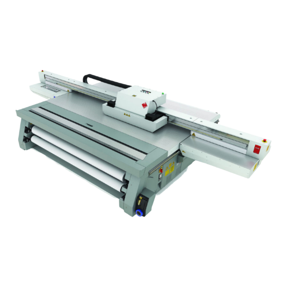
Printer Specifications Introduction The Océ Arizona 400 Series GT and Océ Arizona 400 Series XT are flatbed inkjet printers capable of producing large format images on various rigid and flexible media. The printers consist of a flatbed vacuum table and moving gantry. Media is held flat and stationary on the vacuum table during printing. - Page 17 Printer Specifications Specifications Feature Specification Printing Technology Piezoelectric inkjet using Océ VariaDot™ technology: UV Ink Standard: CMYK Optional: White, Light Cyan, and Light Magenta Varnish Optional Maximum Media Size GT models: 2.5m (98.4") x 1.25m (49.2") XT models: 2.5m (98.4") x 3.05m (120.1") Media Thickness Maximum: 48mm (1.890") Maximum Print Size...
- Page 18 Printer Specifications Chapter 2 - Product Overview...
-
Page 19: Chapter 3 Safety Information
Chapter 3 Safety Information... -
Page 20: Uv Ink And Flush
The MSDS for all UV inks and Flush are available from the corporate Océ Global E- Marketing (GEM) website. For the latest MSDS and PSDS, visit: http://global.oce.com/support/ Caution: UV inks can be harmful if not properly handled. Follow the MSDS guidelines carefully in order to ensure maximum safety. -
Page 21: Uv Curing System
UV Curing System UV Curing System Introduction UV-curable ink need a high energy level of UV light to cure. The UV curing system is made up of two mercury arc lamps attached to the carriage. How to Handle UV Lamp: UV lamps operate at high temperatures. Never touch a lamp in operation. - Page 22 UV Curing System Note: Wear Industrial Protective Eyewear with lenses that block both UVA and UVB. Gloves and long-sleeved work clothes are essential to reduce the skin's exposure to UV emissions. Chapter 3 - Safety Information...
-
Page 23: Safety Interlock System
Safety Interlock System Safety Interlock System Introduction The printer has three Emergency-Stop buttons. The Maintenance Station drawer is part of the safety interlock system. A beacon light indicates the status of the safety system and the printer. Components of the Interlock System Emergency Stop Buttons: These are located on the Operator Control Station, and on each end of the Gantry. -
Page 24: Océ Arizona 400 Series Gt Safety Labels
Océ Arizona 400 Series GT Safety Labels Océ Arizona 400 Series GT Safety Labels Introduction The safety labels are placed at strategic locations on the printer to warn the operator of possible dangers and hazards. It is important to be aware of the meaning of these labels to ensure safe operation of the printer. - Page 25 Océ Arizona 400 Series GT Safety Labels Description Label Machine lockout: a reminder to turn off and lock out the AC power switch before servicing any elec- trical components. Located on the mains power switch. Warning: Electric Shock Hazard Located on the door to the electronics enclosure, the UV lamp power supply cover, the carriage cover, and the vacuum pump enclosure.
- Page 26 Océ Arizona 400 Series GT Safety Labels Description Label Electrical Shock Hazard Equipment Powered by two power cords. Turn off power switch or remove both power cords before servicing Refer to the section "How to Power the Printer On and Off"...
- Page 27 Océ Arizona 400 Series GT Safety Labels Description Label No Step Do not step on the table strut. If pressure is put on the table strut it can bend and thus affect the level of the printer table and therefore print quality.
-
Page 28: Safety Awareness
Safety Awareness Safety Awareness Introduction This section contains two sets of principles that must be followed to assure maximum safety when operating your Océ Arizona printer. The first set uses negative examples to show you things to avoid in order to prevent injury to the operator. The second set of principles illustrates some of the residual risks that are inherent in the operation of the printer. - Page 29 Safety Awareness Avoid these Situations For Your Personal Safety Do not push or force the carriage to move manually if it is al- ready in motion. If you do move the car- riage, a Motion Error message will display and you will have to use the mouse to click Reset on the user inter- face LCD display.
- Page 30 Safety Awareness Avoid these Situations For Your Personal Safety Do not push or force the gantry to move manually if it is al- ready in motion. If you do move the gantry, a Motion Er- ror message will dis- play and you will have to use the mouse to click Reset on the user interface LCD dis-...
- Page 31 Safety Awareness Avoid these Situations For Your Personal Safety Movement of the car- riage up and down may be a crush haz- ard. Do not rest your hands in this area during daily print- head maintenance as this process causes the carriage to move up and down.
- Page 32 Safety Awareness Avoid these Situations For Your Personal Safety Keep a distance of at least 1 m (3 ft.) to the UV light when print- ing. Avoid looking at the UV lamps, especially if you are seated at the same level as the car- riage.
- Page 33 Safety Awareness Arizona Printer Residual Risks Residual Risk Area Hazard A high risk crushing hazard is created by the movement of the carriage and gantry supports. Keep hands away from this area unless the printer power is off. [29] Carriage guard and 45° guard on Gantry Supports A crushing hazard is created by the move- ment of the carriage...
- Page 34 Safety Awareness Residual Risk Area Hazard A high risk crush- ing/pinch hazard is created by the table and the gantry. [31] Table/Gantry Pinch hazard A high risk crush- ing/pinch hazard is created by the table and the carriage. [32] Table/Carriage Pinch Hazard Chapter 3 - Safety Information...
- Page 35 Safety Awareness Residual Risk Area Hazard A high risk crush- ing/pinch hazard is created by the carriage and the gantry when the Z-Axis is moving (carriage moves up or down). [33] Carriage Vertical Movement Pinch Hazard A high risk shearing hazard is created by the gantry and the gantry rail.
- Page 36 Safety Awareness Residual Risk Area Hazard A high risk shearing hazard is created by the gantry and the gantry rail. This pho- to shows another view from the bottom. Do not place fingers or hands in this area. [35] Gantry Shear Hazard Chapter 3 - Safety Information...
- Page 37 Safety Awareness Residual Risk Area Hazard A high risk shearing hazard is created by the carriage and the gantry frame. [36] Gantry Frame Shear Hazard Entanglement hazard A medium risk of fin- ger or material entan- glement is created by the web assembly (IGUS track).
- Page 38 Safety Awareness Residual Risk Area Hazard A medium risk impact hazard is created by the carriage when cy- cling from left to right. [38] Carriage Impact Hazard Heat hazard: the UV lamp assembly and the surrounding car- riage guard can be hot.
-
Page 39: Roll Media Safety Awareness
Roll Media Safety Awareness Roll Media Safety Awareness Introduction This section contains two sets of principles that must be followed to assure maximum safety when operating the Roll Media Option (RMO) for your Arizona printer. The first image uses a negative example to show you a situation to avoid in order to prevent injury to the operator. - Page 40 Roll Media Safety Awareness RMO Residual Risks Crushing/Shear Hazard Do not place your hand near the shaft drive motors when the printer is printing or when the dual foot controls are pressed. Do not place your hand on the Media Roll motor enclosure when the green bea- con light is On as the...
-
Page 41: How To Navigate The User Interface
Chapter 4 How to Navigate the User Interface... -
Page 42: Operator Interface Hardware
Operator Interface Hardware Operator Interface Hardware Introduction The Operator interacts with printer components to print, maintain, and monitor the state of the printer. This section identifies and explains the functions of the hardware. [43] Printer Hardware Operator Interface Components Hardware Interface Components Component Function 1) Main Power Switch... - Page 43 Operator Interface Hardware Component Function 7) Vacuum Gauge Displays the strength of the table vacuum system. If it reads less than 10"Hg, check for vacuum leaks. 8) Print Button Starts the current print job. 9) Maintenance Station Designated area for cleaning the printheads and the under- side of the carriage.
- Page 44 Operator Interface Hardware [44] Vacuum Zone Control Handles Chapter 4 - How to Navigate the User Interface...
-
Page 45: Printer Interface Software
Printer Interface Software Printer Interface Software Introduction The printer software is displayed on the LCD monitor. The interface has six main modules that are accessed by tabs located at the bottom of the display. Click on these tabs to access the modules. - Page 46 Printer Interface Software Operator Interface Module Tabs [46] Interface Tabs Interface Modules Component Function Print Job Control Provides management of all aspects of working with print jobs. (Print tab) It also controls some features of the printer and provides access to Roll Media print controls (if that option is installed).
-
Page 47: Print Job Control Module
Print Job Control Module Print Job Control Module Introduction Print Job Control is the first module displayed when the printer software is loaded. From this module you can manage all aspects of working with print jobs and also control many features of the printer. - Page 48 Print Job Control Module Component Function 3) Pause/Resume To the right is the print job Pause/Resume button and and the Ink System the Ink System Status icon - click to view an ink status report. Status 4) Command Displays icons for actions related to the print jobs and control Toolbar left of the printer.
- Page 49 Print Job Control Module All incoming jobs go directly into the job list or job queue. Selecting a job in the list highlights the job and updates the job information area. The job information area contains offsets, print quality mode information, number of copies and overprints, and the name of the ProductionHouse profile used and the image to be printed is also displayed.
- Page 50 Print Job Control Module Print job This command can do the following actions depending on context: • Activates a selected inactive job by moving it to the active list. • Un-holds a held job. • Un-holds an job that had an error currently. Hold job The command can do following actions depending on context: •...
- Page 51 Print Job Control Module Flatbed Set- A dialog window automatically appears when confirmation is re- tings quired. If it is closed before you select Confirm, it can be reopened by clicking on this button. Media Parameters Enter or confirm the thickness of the media. The printer will auto- matically adjust the carriage height to media thickness and also the print gap.
- Page 52 Print Job Control Module Ink Tempera- This icon controls the ink heater and also displays the ink temper- ture Control ature. The state of the button reflects the status of the ink heater. The heater times out after two hours of inactivity (time can be changed up to four hours by a service technician).
- Page 53 Print Job Control Module Nozzle check This icon populates the active job list with a job that prints a nozzle check pattern. The nozzle check print is used to identify nozzle dropouts that can cause banding and other print quality problems. There are two versions of the nozzle check: Nozzle Check and Nozzle Check Narrow (narrow is for RMO media that is not wide enough for the length of the standard nozzle check print.
- Page 54 Print Job Control Module 7) Job Placement Preview The table placement preview shows the print location and a proportional representation of the image in relation to the table. The zoom button in the bottom right corner activates a popup preview window. If a preview image is not available, an approximately sized white box is used as a placeholder, and the zoom button is not displayed.
- Page 55 Print Job Control Module Offsets A job's vertical and horizontal offset parameters can be changed with the mouse wheel when the mouse cursor is positioned over the field. Rotate the mouse wheel up or down increments or decrements offset at the rate of one unit per notch. Hold the right mouse button and rotate the wheel increments or decrements at the rate of 10 units per notch.
- Page 56 Print Job Control Module result, it may be necessary to print some output in Production Smooth Mode or Quality Mode. Note: When Production Smooth or Squared mode is used, there is a pull-down menu in the Print Job module that allows you to select either Production-Smooth or Produc- tion-Layered (the menu allows you to change how it was configured in your ONYX software).
-
Page 57: Periodic Maintenance
Use the cleaning methods and the maintenance schedule documented in this User manual, the Care and Use Poster, and the Printhead Maintenance video (you can download the poster and video from the customer support web site: http://dgs.oce.com/. Chapter 4 - How to Navigate the User Interface... - Page 58 How to Change Ink Filters in the Maintenance section). As needed Refer to the Océ Arizona Printer Care and Use poster (download from the customer support web site: http://dgs.oce.com/. Chapter 4 - How to Navigate the User Interface...
-
Page 59: Counters Module
Counters Module Counters Module Introduction The Counters module displays counters that are of interest to the operator. It shows counters for each color of ink and the total ink used. It also shows the number of hours a UV lamp was used since last changed. Some of the counters can be reset. Illustration [50] Counters Module Screen Component - function table... -
Page 60: Settings Module
Settings Module Settings Module Introduction The Settings Module allows you to review and change the date and time, network con- nection settings, user interface configurations, printer settings and, if installed, the Roll Media settings. Date and Time Settings [51] Date and Time •... - Page 61 Settings Module Network Connection Settings Note: Typically, DHCP is used to automatically obtain network settings. If "Use DHCP" is selected, the only thing you might want to change is the network name of the printer. The settings are displayed to troubleshoot possible network connection problems. One situation that would require changes is if your network does not use DHCP to automat- ically obtain network settings.
- Page 62 Settings Module User Interface Settings [53] User Interface Settings Settings Available The user interface allows you to change the following features: • Language • Measurement Units • Date format • Time format • Display job/time • Tie lamp controls together •...
- Page 63 Settings Module Printer Settings [54] Printer Settings Allows you to set the following: • Flatbed print gap • Underlay thickness • Table vacuum timeout • End of swath delay • Full carriage travel • Automatic warmup day • Automatic warmup time •...
- Page 64 Settings Module Bottom Margin Specifies the distance left unprinted below the image. Media Move on Unload Specifies the amount of media moved on unload in the selected measurement units. Note: This setting icon is displayed only if the Roll Media Option is installed. Chapter 4 - How to Navigate the User Interface...
-
Page 65: Tools And Utilities Module
Tools and Utilities Module Tools and Utilities Module Introduction The Tools and Utilities Module has six sub-modules: Shutdown, Job Manager, Special Prints, Ink Flush, Spit Catcher Alignment, and the System Logs. When you click on the Tools and Utilities tab, Special Prints always appears first. Click on the other icons to access the sub-modules. - Page 66 Tools and Utilities Module Shutdown Use the Shutdown icon when you need to turn the printer power off. The printer should be left powered On at all times but there are some exceptions such as some service proce- dures, or if the printer requires a reboot. Job Manager The Job Manager allows you to view a select range of print jobs or to delete many print jobs at the same time.
- Page 67 Tools and Utilities Module [57] Special Prints How to Load a Special Print 1) Click a special print to select it in the left window. 2) Click the Add button to place it in the print queue on the right. That special print is now available in the Active job list of the Print Job Control module.
- Page 68 Tools and Utilities Module The Ink Flush Procedure The Ink Flush Procedure is used when the printer is switched from one ink type to an- other. If you insert a new ink bag of a different ink type into the ink bay, the Ink Status screen will appear and prompt you to perform an Ink Flush Procedure.
- Page 69 Tools and Utilities Module Note: When System Logs are generated, any previously saved log files are deleted. Therefore, do not generate a second batch if you have just recently generated log files (unless re- quested to do so by a service technician). Chapter 4 - How to Navigate the User Interface...
-
Page 70: Installation And Upgrade Module
As we are committed to improve and refine the quality and functionality of the Océ Arizona 400 Series GT printer, there will be periodic upgrades to the underlying firmware and printer software. Software updates are available only to customers with a service contract. -
Page 71: How To Operate Your Océ Arizona Printer
Chapter 5 How to Operate Your Océ Arizona Printer... -
Page 72: Training Requirements
ONYX Workflow software (ProductionHouse® or THRIVE) prior to operating the printer. Safety Training Before operating the Océ Arizona 400 Series GT printer, make sure you have read and understood all of Chapter 3 "Safety Guidelines". Océ Operator Training For optimal safety and print quality, all printer operators must have received training by qualified Océ... -
Page 73: How To Power The Printer On And Off
How to Power the Printer On and Off How to Power the Printer On and Off Introduction This section describes how to switch the printer On and Off. When the printer is switched On, the interface software is displayed on the LCD monitor that is located on the Oper- ator Control Station. - Page 74 How to Power the Printer On and Off During the boot-up procedure, the printer software is automatically started. The software displays a splash screen followed by a screen that requests you to raise and then lower the carriage guard. Lift the carriage guard slightly and then replace it. At the control station click on Continue to finish the startup procedure.
- Page 75 How to Power the Printer On and Off How to Power Off Attention: To maintain optimal printer reliability, leave the power on at all times. However, there are exceptions such as for ink flushes, some service procedures, or if the printer requires a reboot.
- Page 76 How to Power the Printer On and Off 24 to 72 hours • Turn off lamps • Perform printhead maintenance when the ink temperature is at least 40° Centigrade (104° Fahrenheit) • Swab print heads • Turn off ink heater •...
- Page 77 How to Power the Printer On and Off Illustration [60] AC Power Switch and Lockout How to Use the Disconnect Device Attention: The AC power plug is the main disconnect device for the printer. For maximum safety, if the printer is moved, the AC power plug must first be unplugged from the printer. Follow the Lock-out procedure above.
-
Page 78: How To Install The Onyx Printer Driver
Series XT printers. Purpose The printer installation file configures the ONYX software so that it knows how to communicate with the Océ Arizona 400 Series GT. This prepares the printer so that the operator can manage print jobs. Before you begin Make sure that the ONYX application software is installed before you install the printer driver. - Page 79 How to Install the ONYX Printer Driver After the printer driver is installed the Configure Printer Port window will launch auto- matically. Select TCP/IP Printer then click on Configure. [61] Configure Printer Port Enter the Network name of the printer (as displayed in Step 3) and make sure <Port 9100>...
- Page 80 How to Install the ONYX Printer Driver Correction If no valid IP address is found, check that the network name of the printer is correct and that port 9100 was selected. Run the Test again. Result When a Valid IP address for the printer is verified, click on OK to complete the configu- ration of the communication link between ProductionHouse and the Océ...
-
Page 81: How To Manage Print Jobs
Daily Start-up and Shut-down How to Manage Print Jobs Daily Start-up and Shut-down Introduction Keep your printer clean and perform all recommended scheduled maintenance to ensure that the printer is ready to produce optimal quality images. When to do The start-up procedure must be performed every morning or after a period of time when the printer has not been used. -
Page 82: How To Set Up A Print Job
How to Set Up a Print Job How to Set Up a Print Job Introduction This section explains how to select an image to print on your printer. The basic steps are outlined here and explained below. More detailed explanations for some of these steps are available in Chapter 4 "How to Navigate the User Interface". - Page 83 How to Set Up a Print Job Measure Media Thickness Use a digital slide caliper or micrometer to accurately measure the media thickness of the media. An error in measurement of media thickness will affect bi-directional alignment and can contribute to the amount of graininess in the printed image or cause a car- riage/printhead crash with the media.
- Page 84 How to Set Up a Print Job table will have vacuum applied when the table vacuum pump is turned on. The vacuum zones are opened or closed using a quarter turn handle. Refer to the next section for details on the dimensions and placement of the vacuum zones. Turn On Table Vacuum Click on the Vacuum button in the top right corner of the printer software display to activate the table vacuum.
-
Page 85: How To Manage The Media Vacuum
The Table Vacuum System How to Manage the Media Vacuum The Table Vacuum System Introduction Your printer uses a low-flow, high-pressure vacuum system to secure media for printing on the printer table. A vacuum pump is used to evacuate the air between the overlay and the table. - Page 86 The Table Vacuum System [64] Closing vacuum zone 4 Vacuum Zone Control Handles The control handles determine the state of the vacuum zones. When the handle is vertical, the zone is open and creates a vacuum in the related area. To close a zone, turn the control handle a quarter turn clockwise to the horizontal position.
- Page 87 The Table Vacuum System Note: Use the vacuum gauge to determine if a zone is properly masked. When the active zone is properly masked the gauge will read at 20"Hg (68 kPa) or higher. Small leaks can re- duce this number and therefore the efficiency of the vacuum. Porous media can also degrade the vacuum effect.
-
Page 88: Using Vacuum Zones
The printer ships with a vacuum field configured to support either metric or imperial size media. For the Océ Arizona 400 Series GT vacuum control valve handles are used to manage these zones. The printer has five control valves that determine the zones that are active when the table vacuum pump is on. - Page 89 Using Vacuum Zones The metric configuration is designed such that zone 6 can be reconfigured by a service representative from the 2.5m x 1.25m area size to 4'x8'. [65] Metric Vacuum Zones Print Metric Zone Map A map of the vacuum zone can be printed on the table to help with the position of media over the zones.
- Page 90 Using Vacuum Zones With no media present, print the zone map directly onto the printer table. [66] Vacuum Zones Metric - GT Imperial Vacuum Zones The following shows the media dimensions that are available with the recommended Imperial vacuum zones. The name of the zone indicates which vacuum handle controls that zone.
- Page 91 Using Vacuum Zones the maximum supported size could be increased by a service representative. This allows media to reach the 49.2 x 98.4 inches boundary. [67] Imperial Vacuum Zones Print Imperial Zone Map A map of the vacuum zone can be printed on the table to help with the position of media over the zones.
- Page 92 Using Vacuum Zones With no media present, print the zone map directly onto the printer table. [68] Vacuum Zones Imperial - GT Chapter 5 - How to Operate Your Océ Arizona Printer...
-
Page 93: How To Manage Media
Océ Display Graphics Systems has conducted extensive testing of many media. Since the Océ Arizona 400 Series GT printer is capable of imaging on a wide range of material, we encourage you to explore various media so that you can establish your own criteria for achieving high quality images in your work environment. - Page 94 How to Handle Media humidity changes of the working environment. Ideally, store media in the same envi- ronmental conditions as it will be used. • Store media flat to reduce tendency to bow. Do not use creased, damaged, torn, curled, or warped material.
- Page 95 Customer Support web site. See Appendix A of this document for a list of available bulletins or visit the web site to download bulletins: http://dgs.oce.com/ Thermal Expansion of Media When imaging on media that will expand when subjected to heat (e.g., styrene or Plexiglas, etc.), don’t wedge the media by butting other material against it as this may cause the...
- Page 96 How to Handle Media cation of the cards. Note: these cards can be stacked, but if more than two of them are stacked, the carriage will collide with them if you print at zero media height. Always check the height if you use multiple stacked cards so that they match the height of your media and the set the carriage height accordingly.
-
Page 97: Chapter 6 How To Operate The Océ Arizona 400 Series Xt
Chapter 6 How to Operate the Océ Arizona 400 Series XT... -
Page 98: Océ Arizona 400 Series Xt Features
*Océ Arizona 400 Series XT Features Introduction The Océ Arizona 400 Series XT is the same as the Océ Arizona 400 Series GT in the following areas: Gantry, Carriage, RMO capable, and White Ink option. The Océ Arizona 400 Series XT printer has a larger table and two vacuum pumps. These pumps provide vacuum for the vacuum zones. - Page 99 *Océ Arizona 400 Series XT Features Note: The Center Zone is referred to as Zone C. Definition The Océ Arizona 400 Series XT is a flatbed inkjet printer capable of producing large format images on various rigid and flexible media. The printer consists of a flatbed vacuum table and moving gantry.
-
Page 100: How To Use The Océ Arizona 400 Series Xt Vacuum System
How to Use the Océ Arizona 400 Series XT Vacuum System How to Use the Océ Arizona 400 Series XT Vacuum System Introduction The Océ Arizona 400 Series XT uses a vacuum system to secure rigid media for printing on the printer table. Two independent vacuum pumps provide vacuum to the table, which is divided into multiple vacuum zones. - Page 101 How to Use the Océ Arizona 400 Series XT Vacuum System Purpose The vacuum system holds the media in place on the printer table. The zones are arranged to accommodate common media dimensions. If a zone is activated, you must mask off any part of it that is not covered by the media.
-
Page 102: How To Print With Dual Origins
How to Print With Dual Origins How to Print With Dual Origins Introduction Due to the larger table size and the vacuum zone arrangement of the Océ Arizona 400 Series XT printer, it is possible to print in an alternating 2-up arrangement with panels up to 1.25 x 2.5 meters (4 x 8 feet) in size. - Page 103 How to Print With Dual Origins Enter 2 or more copies in the Job Parameters Copies field. Click on the Enable Dual Origin box when it appears to make it active. Note: When Dual origins is enabled, a scaled view of the image appears on the screen preview in Zone A and a gray-scale box that represents the image appears in Zone B.
- Page 104 How to Print With Dual Origins Chapter 6 - How to Operate the Océ Arizona 400 Series XT...
-
Page 105: Chapter 7 How To Operate The Roll Media Option
Chapter 7 How to Operate the Roll Media Option... -
Page 106: Roll Media Option Hardware
Roll Media Option Hardware Roll Media Option Hardware Introduction The Roll Media Option (RMO) allows printing on media that is supplied on a roll. [72] Roll Media Option Components Component Locations Roll Media Hardware Component Function 1) Dual Foot Pedal Switches 6) Media Access Door 2) Media Drive Couplers 7) Media Cut Guide... - Page 107 Roll Media Option Hardware Roll Media Hardware Component Function 1) Dual Foot Pedal The dual foot pedal switches areused to control media Switches feed in both forward and reverse directions. Function varies depending on whether media is loaded or unloaded. 2) Media Drive Couplers The couplers keep the media shafts in place and engaged to the drive motor.
-
Page 108: Roll Media Option Specifications
Specifications associated with the use of roll media are indicated in this section. Note: The Océ Arizona 400 Series GT and the Roll Media Option must be operated in accor- dance with the environmental conditions specified in the Océ Arizona 400 Series GT Site Preparation Guide and all safety requirements noted in this document. - Page 109 Roll Media Option Specifications End of roll waste is the media that cannot be printed at the end of the supply media roll. This will vary slightly depending on the attachment method that was used to secure the media to the media core. Chapter 7 - How to Operate the Roll Media Option...
-
Page 110: Foot Pedal Switch Functions
Foot Pedal Switch Functions Foot Pedal Switch Functions Introduction The foot pedal switches are used to control the forward and reverse movement of media shafts. Summary of Dual Foot Pedal Switch Functions The following table indicates the foot pedal functions for various RMO states. Actions for foot pedals in various states Media Reverse Media Forward... -
Page 111: Roll Media Manager
Roll Media Manager Roll Media Manager Introduction The Roll Media Manager is the area of the printer software where you prepare to print on roll media. With this menu you can load and unload media, change media type and parameters, and initialize the printer to prepare it to print on roll media. This section introduces the icons in the Roll Media Manager that are necessary to load and initialize a roll media print job. - Page 112 Roll Media Manager Roll Media Manager Menu Roll Media Manager Icons Icon Function Load Allows the operator to load new media. Set the foot pedal switches to the Load state. Unload Prepares the RMO to allow the operator to cut the existing media, remove it, and replace it with a new roll.
-
Page 113: How To Load Media
How to Load Media How to Load Media Introduction This section explains how to load a new roll of media. It details the following actions that are associated with loading media: • A) Load Supply Media Roll On Media Shaft •... - Page 114 How to Load Media When to do This section explains how to load new media when none is currently loaded. If media is already loaded, first read the section How to Cut and Unload Media. Before you begin It is very important that the media is wound properly onto the core when it arrives from the manufacturer.
- Page 115 How to Load Media A: Load Supply Media Roll On a Media Shaft Place an empty media shaft on a suitable flat work area, positioned as shown, so that the 5mm hex key is inserted on the right side of the shaft to lock and unlock the core locks. [76] Unlock the Media Shaft Core Locks To unlock the media shaft core locks (1) turn counter-clockwise with the supplied 5mm hex key (2).
- Page 116 How to Load Media Accurately center the media using the supplied ruler. Media should be centered within 1mm on the ruler. [77] Ruler to Center Media Note: The supplied ruler has both metric (millimeters) and imperial (inches) scales. When a media roll is centered on the shaft, and the ruler is placed as shown in the photo, the value on the ruler scale will match the width of the roll.
- Page 117 How to Load Media Note: Make sure that the core lock and coupler end of the shaft are on the right side of the printer. Lock the take-up media shaft core locks with the 5mm hex key. C: Loading the Media - Standard Method The standard way to load media is quick and efficient and ensures minimum waste of material.
- Page 118 How to Load Media Thread the media under the media tension bar (Note that the media is threaded for Print Side Out in the photo below). Pay out media with the foot pedal as required. [78] Thread Media Under Tension Bar (Print side out) Open the media access door at the top of the Roll Media unit, then reach down through the open door to grasp the media and feed it up and over until it reaches the take-up roll.
- Page 119 How to Load Media Check alignment of the media by feeding it down to the supply roll and make sure that the edge lines up with the edge of the supply roll. [80] Align Media Rewind the media by continually pressing down the left foot pedal until it is positioned where it can be taped to the take-up core.
- Page 120 How to Load Media Tape the media onto the core. The media should have a clean straight edge prior to taping. First tape the center of the media to the core, and then tape both ends of the media. [81] Tape Media to the Take-up Roll Core Note: Important: Use the supplied ruler to check that the edge of the take-up roll is aligned within 1mm of the feed roll.
- Page 121 How to Load Media Once you have aligned the media edges to the supply roll, without moving the media any further, tape the media to the platen. [82] Tape the media edges to the platen Pull the hanging media edge taut and cut the media off from each edge at an angle to result in a point just below the take-up core as shown here.
- Page 122 How to Load Media Tape the pointed end of the media to the take-up core as shown below. [84] Tape media to core Remove the tape you used to hold the media to the platen. Select the "Initialize" icon from the Roll Media Manager to prepare the RMO for printing. After initialization has completed, advance the media until the cut area is wound onto the core across the width of the roll and verify with the ruler that the supply and take-up edges are at the same location.
-
Page 123: How To Unload And Cut Media
How to Unload and Cut Media How to Unload and Cut Media Introduction This section explains all of the actions associated with how to cut and unload media when there is still some media left on the supply roll. Unload Media Summary The following actions are associated with unloading media: •... - Page 124 How to Unload and Cut Media Click on OK to proceed. C: Remove Media from the Take-up Shaft in Printer or Remove Take-up Shaft If you want to remove the printed images without removing the take-up roll from the printer you can press the left pedal to rotate the take-up media shaft in the reverse direc- tion.
-
Page 125: How To Set Up A Roll Media Job In Productionhouse
How to Set Up a Roll Media Job in ProductionHouse How to Set Up a Roll Media Job in ProductionHouse Introduction Print jobs can be specified as either a roll job or a flatbed job in ProductionHouse. The job type can be changed after the print job is transferred to the printer. Purpose The operator can choose the type of desired print job and also put a hold on it so it will not print automatically. - Page 126 How to Set Up a Roll Media Job in ProductionHouse Note: If you don't set a hold in ProductionHouse, it is also possible to disable the Roll media print queue at the printer. To do this click on the Roll icon in the command toolbar of the Print Job module so that it become dim (grayed out).
-
Page 127: How To Print On Roll Media
How to Print on Roll Media How to Print on Roll Media Introduction To print an RMO image, media must be loaded and the RMO initialized. Use the Print Job module and the Roll Media Manager to prepare and start the print job. How to Print on Backlit Media If your roll media is transparent or opaque and you are going to backlight the image and you want to increase the density, set Quality mode in ProductionHouse. - Page 128 How to Print on Roll Media Click on the Roll Manager icon to enter the Roll Media Manager dialog window. [88] Roll media manager Enter the Media width for the roll media that you have loaded. Note: If the media width entered is less than 1067 mm (3.5 ft) the standard nozzle check will not fit across the media.
- Page 129 How to Print on Roll Media Note: Any changed parameter in the dialog window will be applied to the next roll media print job, even if the change was not saved. This allows temporary changes to the parameters without the need to save that media. [89] Roll Media Manager Keyboard Note: There is always at least one media in the list that is called Default Media.
- Page 130 How to Print on Roll Media Result Any print jobs that are in the queue, not on hold, and marked as roll jobs will print. There is no explicit confirmation required to start a roll media print job. Any roll media jobs in the print queue will start to print immediately.
-
Page 131: How To Determine The Media Advance Correction Factor
How to Determine the Media Advance Correction Factor How to Determine the Media Advance Correction Factor Introduction When you print on roll media, there can be discrepancies in the amount the media ad- vanced during each print swath. This is referred to as media stepping. It can cause banding to occur, in the form of either dark lines or white gaps. - Page 132 How to Determine the Media Advance Correction Factor In the 'Roll Media Manager' menu you can select the 'Media Advance Correction Factor' (MACF) and enter a value from 0 to 100. The default value is 50. You can enter a lower value to correct for white gaps or raise the value to correct for dark lines.
-
Page 133: How To Use Media Edge Protectors
How to Use Media Edge Protectors How to Use Media Edge Protectors Introduction Some media tend to have dust and fiber that clings to the edge of the media roll. When released near the RMO (Roll Media Option) unit platen, these particles can find their way into the printhead nozzles and cause dropouts that reduce image quality and produce banding. - Page 134 How to Use Media Edge Protectors Bend the other two creases slightly so that they have a V shape when viewed, as illustrated in the side view figure below. [91] Side View of Media Protector Bend the height adjustor (small triangle in the top corner of the edge protector) slightly and then straighten it again.
- Page 135 How to Use Media Edge Protectors Press down on the tape to fasten the protector in this position. [93] Edge Protector in Position Note: The adhesive on the edge protector can be re-used approximately ten times. If you find that it is not holding the protector in place, then use a new one. Result The media edge protectors will reduce the amount of fiber and other debris.
- Page 136 How to Use Media Edge Protectors Chapter 7 - How to Operate the Roll Media Option...
-
Page 137: Chapter 8 How To Use The Static Suppression Upgrade Kit
Chapter 8 How to Use the Static Suppression Upgrade Kit... -
Page 138: Reduce Static With A Static Suppression Kit
Reduce Static with a Static Suppression Kit Reduce Static with a Static Suppression Kit Introduction The Océ Static Suppression Upgrade Kit is a Commercial Product that can be ordered as part # 3010106603. If you are experiencing static-related imaging problems this op- tional upgrade kit contains an ionizer bar that provides a solution to reduce static. - Page 139 Reduce Static with a Static Suppression Kit How to Activate the Static Suppression Ionizer Bar Press the Settings tab on the printer interface screen. Click on the Printer icon. If the Ionizer Bar option is set to Off, set it to ON (this option is not displayed if the ionizer bar is not installed).
- Page 140 Reduce Static with a Static Suppression Kit Loosen the bracket mount screw and then slide the bracket up in the keyed slot to remove [95] Bracket Mounted Low Turn the bracket 180 degrees and then fit the other keyed slot over the bracket screw. Slide the bracket mount until the screw is located in the smaller end of the keyed slot.
-
Page 141: Chapter 9 How To Work With White Ink And Varnish
Chapter 9 How to Work With White Ink and Varnish... -
Page 142: Operator Guidelines For White Ink And Varnish
Operator Guidelines for White Ink and Varnish Operator Guidelines for White Ink and Varnish Introduction This chapter is necessary only if you have a printer with the white ink or varnish option. This includes the Océ Arizona 460 GT/XT and the Océ Arizona 480 GT/XT (the 440 GT/XT does not support varnish or white ink). - Page 143 The video can be viewed from the Customer Support page and is also available to download: http://dgs.oce.com/. Note that the video discusses the Océ Arizona 550, but the procedure is the same for the Océ...
-
Page 144: White Ink Workflow Overview
White Ink Workflow Overview White Ink Workflow Overview Introduction Océ Arizona printers with the White Ink Option provide under-printing for non-white media or objects, over-printing for backlit applications on transparent media and/or printing white as a spot color. This section describes how the printer provides white ink support, gives a summary of the workflow data preparation, and also shows some of the ways white ink can be used in print applications. - Page 145 White Ink Workflow Overview Printer Flood Fill Versus Job Data White ink can be printed using flood fill data generated by the printer or job data. A printer flood fill cover the whole image area while spot data is assigned in specific areas. Job data is separated by the ONYX software into six data planes: C, M, Y, K, Spot 1, and Spot 2.
- Page 146 White Ink Workflow Overview Layers can be defined at any of the following locations: • Defined in the media when the media is created - Mode Options • Selected in a Quick Set - Media Options • Modify the printer settings of a processed job in RIP Queue - right-click the job, edit printer settings.
-
Page 147: Varnish Workflow Overview
Varnish Workflow Overview Varnish Workflow Overview Introduction Océ Arizona printers with the Varnish Option can use varnish as a flood coat or can create spot features that place varnish in select areas in a print job. The printing of varnish is applicable only to flatbed printing and is not available with the RMO. - Page 148 Varnish Workflow Overview Printer Flood Fill Layer Configuration in an Onyx Media Model does not require any pre-rip file preparation and is the easiest method of achieving varnish output. All that is required is to set up the Print Mode to use a Varnish Flood. The printer flood encompasses the bounding box (the outer border of the image) of the file being processed.
- Page 149 Varnish Workflow Overview Summary Follow these simple points to produce good results with the Varnish option: • Clean the surface of the media before each print. If you gloss coat a rough stock it may be difficult to "fill in the surface" and achieve a smooth high gloss finish. •...
-
Page 150: How To Configure Onyx Software For White Ink And Varnish
How to Configure ONYX Software for White Ink and Varnish How to Configure ONYX Software for White Ink and Varnish Introduction This section describes how to configure ONYX software (either ProductionHouse or THRIVE) to recognize white ink or varnish workflow elements and thus allow you to apply the approach that is best for your print job application. - Page 151 How to Configure ONYX Software for White Ink and Varnish In your Quick Set, or in Preflight/Job Properties/Postscript turn off two-stage processing (make sure the box is not checked). [100] Turn off Two Stage Processing Result ONYX software is now prepared to accept print jobs with white ink or varnish data. Chapter 9 - How to Work With White Ink and Varnish...
-
Page 152: White Ink Quickstart
Note: Sample Media models for white ink are available for download from the DGS website: http://dgs.oce.com/. These media are documented later in this chapter (see How to Use Media Models to Print With White Ink). How to Print a Simple Job Using White Ink Open an image of your choice using the media model with a Quality-Layered print mode. - Page 153 White Ink QuickStart To define a white flood layer, modify the printer settings of a processed job in RIP Queue - right click the job, edit printer settings, select Quality-Layered for the Printer Print mode, then select Define Layers [101] Quality Layered If you want to print first surface (e.g.
- Page 154 White Ink QuickStart Select White Flood Fill (Printer). [102] Define Layer Put the printer back online in ONYX RIP-Queue and send the job to the printer. Note: To preview the layer order in the image, click Layers in the printer software. Print the job.
-
Page 155: Varnish Quickstart
Sample Media models for varnish are available for download from the Customer Support section of the DGS website: http://dgs.oce.com/. These media models are documented later in this chapter (see How to Use Media Models to Print With White Ink or Varnish). - Page 156 Varnish QuickStart To set up a varnish printer flood, modify the printer settings of a processed job in RIP Queue - right click the job, edit printer settings, select Quality-Layered for the Printer Print mode, then select Print Varnish With: Flood Coat (Printer). [103] Select Varnish Put the printer back online in ONYX RIP-Queue and send the job to the printer.
-
Page 157: White Ink And Varnish Print Jobs
How to Select a Printer Flood Fill White Ink and Varnish Print Jobs How to Select a Printer Flood Fill Introduction When working with white ink or varnish you can choose the workflow that best fits your needs. There are three main approaches to white ink/varnish workflow with your printer: •... - Page 158 How to Select a Printer Flood Fill How to Prepare a Printer Flood Fill Layer for White ink Open the print job in your ONYX software and use a media model that includes the Quality-layered print mode. Note: The file must be sized at the final output dimensions required for the flood area. Define one of the data layers as a white flood layer.
- Page 159 How to Select a Printer Flood Fill Send the job to the printer. Chapter 9 - How to Work With White Ink and Varnish...
-
Page 160: How To Create Spot Data With The Spot Layer Tool
How to Create Spot Data with the Spot Layer Tool How to Create Spot Data with the Spot Layer Tool Introduction The Spot Layer Tool can be used to set up two spot data planes that define areas where spot 1 and spot 2 data are added to a print job. The tool is used with the Océ Arizona 460 and 480 printers as they both have two extra channels that provide varnish or white ink as well as CMYK. - Page 161 How to Create Spot Data with the Spot Layer Tool Generation Options - Set Mask The mask allows you to determine the area that you wish to print with spot data. Setting the mask color is optional. If the image you are printing contains white or varnish data in more than the mask area, you will need to set up a different background color not used anywhere else in the file to use as your mask.
- Page 162 You will learn how to isolate the white area of your image in Illustrator so that it will be recognized by the Spot Layer Tool and then printed as white by the printer. Download Application Bulletin 22 from the Customer Support web site: http://dgs.oce.com/. Chapter 9 - How to Work With White Ink and Varnish...
- Page 163 How to Create Spot Data with the Spot Layer Tool How to Access the Spot Layer Tool Open a print job in Preflight. Select the Color Corrections tab. Click on Tools and select Spot Layer Tool. This will open the feature set. Note: If the Enable checkbox won't activate, the media you used to open the job has not been configured with the Quality-Layered print mode.
-
Page 164: How To Create White Spot Data In Photoshop
How to Create White Spot Data in Photoshop How to Create White Spot Data in Photoshop Introduction This section explains how to prepare images that include white spot data with raster-based image editing applications such as Adobe Photoshop®. In order to print with white ink, you must have a media properly configured for the use of white spot data (see the section, How to Create a Media for White Ink). - Page 165 How to Create White Spot Data in Photoshop How to Prepare an Image in Photoshop Use the following steps to create a new spot channel layer: Open the desired file in PhotoShop (if the file is in RGB mode, then convert it to CMYK mode).
- Page 166 How to Create White Spot Data in Photoshop • Name – Enter the name “Spot 1”. This name is specifically reserved in RIP-Queue for this type of workflow, using any other name requires more steps to make spot in- formation addressed by the Rip software. Note: For instructions on how to use a naming convention other than Spot 1, refer to the sub-section at the end of this section "Naming Your Spot Data".
- Page 167 How to Create White Spot Data in Photoshop [110] Flood 100 PSD [109] Flood 50 PSD In some cases, it may be easier to select the area in which you don't want any white ink data and then select the inverse. [111] Select [112] Select Inverse It is also possible to edit the spot channel much as you would any other data in a Photo-...
- Page 168 How to Create White Spot Data in Photoshop • If you intend to use this file in a vector-based program such as Illustrator, save it as a .PSD file in order for all channel information to be carried over. The white spot color is printed in the order it appears in the Channels palette, with the spot channel printing underneath CMYK data.
-
Page 169: How To Create White Spot Data In Illustrator
How to Create White Spot Data in Illustrator How to Create White Spot Data in Illustrator Introduction This section explains how to prepare images that include white spot data with vector- based image editing applications such as Adobe Illustrator®. In order to print with white ink, you must first have a media properly configured for the use of white spot data (‘’... - Page 170 How to Create White Spot Data in Illustrator Within the Add Swatch dialog, enter the following information: [114] New Swatch [115] New Swatch Name • Name – Enter the name “Spot 1”. Note: For instructions on how to use a naming convention other than Spot 1, refer to the sub-section at the end of this section "Naming Your Spot Data".
- Page 171 How to Create White Spot Data in Illustrator [116] Color Swatch [117] Spot Swatch Use the new swatch for any objects or fills which need to be printed with white ink. Clicking on new spot color swatch will make this the default fill color for this document. Select element you would like to be treated with Spot information and choose the fill swatch.
- Page 172 How to Create White Spot Data in Illustrator Select the white ink object or objects that you want to overprint and place these above the image data layer that you would like to print. Or if you want them on the same layer the white ink objects should be in front of the image data.
- Page 173 How to Create White Spot Data in Illustrator Note: While it is possible to set Overprint opacity levels less than 100%, ProductionHouse software only processes full opacity data. The opacity of regular knockout white data can be set as desired. [120] Overprint Attributes The images below shows white spot data with knockout and overprinting.
-
Page 174: How To Place Raster Images In Illustrator
How to Create White Spot Data in Illustrator Note: When processing this file in ProductionHouse, media layers must be set up with a spot layer to represent this data, as Illustrator identifies this as a Spot, rather than a flood layer. [123] Pixel Preview Flood How to Place Raster Images in Illustrator Begin by placing the desired file. - Page 175 How to Create White Spot Data in Illustrator Once the file has been brought into program, click the Embed button to place it in the Illustrator document. This step is necessary in order to make use of all channel data contained in the file.
- Page 176 How to Create White Spot Data in Illustrator [127] Select Clipping [128] Copied Path Then move the new layer outside of the group it is in to un-link it from the clipping path. [129] Moved Channel Once outside the group, make sure path is selected and fill it with your Spot 1 color. Chapter 9 - How to Work With White Ink and Varnish...
- Page 177 How to Create White Spot Data in Illustrator Once that is done, replace path in the group above the image and clipping layers. Ensure that Overprint is turned on. [130] Replace path in Group Save the file. Note: In testing, we have found the .eps file format to be the best. However, Postscript and PDF files will work as well, but may require some additional setup.
- Page 178 How to Create White Spot Data in Illustrator Create a box around your image using the Rectangle Tool or other appropriately shaped box tool. Make sure this new box is selected and select Fill swatch located at the bottom of the Il- lustrator toolbar.
- Page 179 How to Create White Spot Data in Illustrator How to Name Your Spot Data In order for ProductionHouse to correctly distinguish and address Spot data, naming conventions for this data must be adhered to both in the image editing creation stage and the Rip.
- Page 180 How to Create White Spot Data in Illustrator Open file in Preflight and access the Color Management/Edit Profiles tab. Click on Spot Channel Replacement box. [134] Spot Channel Replacement Enter the new name in PostScript Spot Color Name in Spot 1 space. Click OK to save your settings.
-
Page 181: How To Use Media Models
DGS web site in the Customer Support area at http://dgs.oce.com/. These media models provide a good start point for the white ink workflow. However, we recommend that you create your own new ones to ensure optimal success with your particular white ink workflow. - Page 182 How to Create a Media for White Ink Print Jobs is on how to create the media. The media is essential to white ink workflow, and the rest of the media model creation simply ensures optimal image quality. Note: The term "media" can be confusing as it really has two meanings in the context of your Onyx workflow.
- Page 183 How to Create a Media for White Ink Print Jobs Note: The next section will show you how to create a media model that is configured for white ink printing. Return to the Media Manager Home page. How to Create a Media Model for White Ink From the Home page in Media Manager click >...
- Page 184 How to Create a Media for White Ink Print Jobs Note: In order to make use of the multi-layered print mode, the Quality-Layered Mode must be used. It is also possible to generate white flood data with limited functionality in one layer using the Production, Quality and Fine-Art CMYKW modes.
- Page 185 How to Create a Media for White Ink Print Jobs Note: If you change the name of your Spot color to anything other than Spot 1, the data file you prepare for this media must also make use of the exact same spot color name. Also, this name must be set up in Color Management/Edit Profiles/Spot Channel Replacement.
- Page 186 How to Create a Media for White Ink Print Jobs Note: Most of the steps for creating a media with a white spot are similar to the regular workflow. Please do not attempt these steps unless you have experience creating media profiles. The profiling steps and color theory are not explained in detail and are not covered in this document.
- Page 187 How to Create a Media for White Ink Print Jobs In the Mode Options window, select the Quality-Layered Print Mode. Click OK to save these settings and close the window. [141] Define Layers Once you select a mode the Define Layers button appears under the Printer Print Mode. [142] Define Layers Chapter 9 - How to Work With White Ink and Varnish...
- Page 188 How to Create a Media for White Ink Print Jobs Click on Define Layers to open this dialog and the following window should appear. [143] Define Layers This is where you can set up how you want the ink to behave in each layer. It is not nec- essary to use all 3 available layers;...
- Page 189 How to Create a Media for White Ink Print Jobs drop down menu and click on the Custom tab to the right of this. This action will bring up the Define Single Layer window. [144] Define [145] Define Single Layer Note: The data used in the white spot layer needs to comes from the spot data found in the image you have created in an image editing program such as Adobe Illustrator.
- Page 190 How to Create a Media for White Ink Print Jobs Configure White Flood Layers If you want to create linearizations and ICC profiles with a white underlay, we recommend you configure one or more flood fill white layers for white based on the desired opacity for your application and one layer for CMYK data.
- Page 191 How to Create a Media for White Ink Print Jobs in the Advanced tab in the Spot field. In testing, we have found this value is usually ac- ceptable if left at 100%. [147] Set Ink Restrictions If you are printing on clear materials make sure the opacity is acceptable as well as exhibit- ing no over-inking artifacts.
- Page 192 How to Create a Media for White Ink Print Jobs Note: If you use a strip device such as the Gretag-MacBeth EyeOne, you may get invalid readings for the white data. To ensure that you get usable spot data points for each measurement, you will need to use the data from the black channel.
- Page 193 How to Create a Media for White Ink Print Jobs Set Ink Limits To print the Ink Limits swatch: Click > Print Swatch and determine Ink Limits as usual. Look for bleed in the columns and choose a value where you can eliminate waste ink. Click>...
- Page 194 How to Create a Media for White Ink Print Jobs media from Rip-Queue. Remember that changes to the layer order and ink color usage may also be made on a per job basis from Rip-Queue. Right click on the desired file then choose Edit/Printer Settings.
-
Page 195: How To Create And Use Quick Sets
How to Create and Use Quick Sets How to Create and Use Quick Sets Introduction This section describes how to create and use Quick Sets. A Quick Set contains a set of printer configuration parameters that are defined and then saved for use with print jobs that will benefit from that particular set of parameters. - Page 196 How to Create and Use Quick Sets • Get Media and Page Size from Printer Unselect "Get Media and Page Size From Printer" so that you can select the media, print mode, and layer definitions to be associated with the Quick Set. First select a media name that contains a Quality Layered Printer Print Mode, then verify/select a Print Mode that contains a Quality Layered Print Mode "...
- Page 197 How to Create and Use Quick Sets How to Create or Edit a Quick Set for White Ink In ProductionHouse RIP-Queue select your printer, and click on the Configure Printer button. This opens the Configure Printer dialog. From the Quick Sets tab, select the Quick Set you want to edit or copy (or select New to build one from defaults).
- Page 198 How to Create and Use Quick Sets Chapter 9 - How to Work With White Ink and Varnish...
-
Page 199: Chapter 10 Ink System Management
Chapter 10 Ink System Management... -
Page 200: Arizona Printer Inks
Arizona Printer Inks Arizona Printer Inks Introduction Océ Arizona printers use two types of UV-curable inks, referred to as Océ IJC255 and Océ IJC256. Both inks are easy to maintain, requiring daily maintenance with a vacuum suction device and a weekly physical cleaning (swabbing) of the printheads. The Océ IJC255 White ink and all of the Océ... - Page 201 Application Bulletin 28 - "Selecting Appropriate Océ Ink for Your Applications: Océ IJC255 or Océ IJC256" on the customer support web site at http://dgs.oce.com/. These inks have very little odor, but for optimal safety some ventilation is needed. The printer should operate in an area where a good standard of general ventilation is available at 5 to 10 air changes per hour.
- Page 202 Arizona Printer Inks coolant fluid through the printheads. An internal thermostat on each printhead provides temperature feedback. The condition of the printheads is maintained by periodic cleaning at the maintenance station on the gantry. During this procedure the operator suctions the printhead nozzle plates, removing ink and possible contaminates in the process (details of this procedure are available in the Maintenance section).
- Page 203 MSDS (Material Safety Data Sheets) for each color of ink and the UV Flush are available from the corporate Océ Global E-Marketing (GEM) website. For the latest MSDS and PSDS, visit: http://global.oce.com/support/. Read and periodically review this safety in- formation to ensure optimal safe handling procedures and proper emergency responses are followed when using UV inks and flush.
-
Page 204: How To Change Ink Bags
How to Change Ink Bags How to Change Ink Bags Introduction The ink is supplied in 2 liter or 800 milliliter bags, dependant on the printer model (White ink comes in 1 liter bags for all models). The bags have a non-spill coupler bonded into the top corner. - Page 205 How to Change Ink Bags Illustration [151] Remove the Quick-Release Coupler How To Change an Ink Bag Attention: For personal safety, we recommend that the operator always wear nitrile gloves, a protective apron, and safety glasses with side shields when handling inks. Open the clear plastic door on the Ink Station.
- Page 206 How to Change Ink Bags Chapter 10 - Ink System Management...
-
Page 207: Error Handling And Troubleshooting
Chapter 11 Error Handling and Trou- bleshooting... -
Page 208: Troubleshooting Overview
Troubleshooting Overview Troubleshooting Overview Introduction This section covers general problems that may occur with the printer. Malfunctions that trigger system error messages can be caused by human error, a system malfunction, an interface cable malfunction, mechanical printer malfunction and/or printer firmware failure. - Page 209 Troubleshooting Overview tion. The printer relies on this service for primary branch protection. If the printer is without power, check the local supply voltage and verify that it is set correctly. Example 2 Drops of Ink Appear on the Media •...
-
Page 210: How To Improve Quality When Banding Occurs
How To Improve Quality When Banding Occurs How To Improve Quality When Banding Occurs Introduction Banding can occur in an image for a number of reasons. Typically it occurs due to neighboring nozzles that do not fire or multiple nozzles that fire with poor directionality. This can occur if the printer sits idle for an extended period of time (e.g., overnight or longer), or if debris has been picked up from the media or table by a printhead. -
Page 211: Chapter 12 Printer Maintenance
Chapter 12 Printer Maintenance... -
Page 212: Maintenance Guidelines
Maintenance Guidelines Maintenance Guidelines Introduction The printer operator is responsible for the regular maintenance of the printer. This section provides detailed information about what is required for proper printer maintenance. While Océ Display Graphics Systems furnishes guidelines for periodic maintenance, the optimum maintenance schedule evolves from careful observation of your printer over a period of use. -
Page 213: Clean Carriage
Maintenance Guidelines Note: Do not bump the carriage or gantry as this can cause dropouts in the printhead nozzles. A hard bump can break the meniscus vacuum in the ink lines and thus allow air into the lines, which blocks the nozzle until a purge is performed. Also some procedures, such as Printhead Maintenance, require that you slide open the door to access the maintenance station. -
Page 214: Maintenance Procedures
You may also need to install a humidifier if humidity is below the re- quired minimum defined in the Océ Arizona 400 Series GT Site Preparation Guide (30% to 70%, non-condensing is the suggested range for operating the printer). -
Page 215: Printhead
Clean Carriage Underside Caution: The underside of the UV lamps may be hot, avoid touching them. How to Clean the Carriage Underside Slide the maintenance station drawer out from under the carriage. Press the middle switch to raise the carriage to its maximum height. Prepare a clean poly wipe cloth as shown below. -
Page 216: Maintenance
Clean Carriage Underside Note: The Océ IJC256 ink formulation causes a more sticky ink build-up between nozzle plates when compared to Océ IJC255 ink. This ink build-up requires cleaning with a lint-free cloth wetted with flush, rather than a dry one. Follow up with a dry cloth to ensure that all residual flush is cleaned from the surface. -
Page 217: Printhead Maintenance
The video can be viewed from the main Customer Support page and is also available to download: http://dgs.oce.com/. When to do Maintenance occurs at the start of the day (after the printer has warmed up) or when necessary (misfiring nozzles, banding in image, etc.). -
Page 218: Maintenance
Printhead Maintenance Note: More maintenance is required in dusty environments, or when there are fibres protruding from the media, or when printing on reflective media such as glass or metal (more re- flected UV light hits the printheads). When printing on reflective media it is advised to monitor the nozzle check and printhead nozzle plates and to perform additional printhead maintenance, if required, to prevent ink from partially curing/gelling on the printhead nozzle plates. -
Page 219: Maintenance
Printhead Maintenance Note: Maintenance Station Switches: There are three switches inside of the maintenance station . They can be operated in any order. For example, you can press the middle switch to raise the carriage to remove debris from the underside of the carriage even when a purge isn't required. Illustration [154] Maintenance Station Switches Left switch to activate... -
Page 220: Maintenance
Printhead Maintenance Attention: Be careful not to snag the coiled suction-head hose when removing the suction-head from the holder. Press the Suction button to turn on the suction pump. Pick up the suction-head from the tray at the left end of the maintenance station. Wipe the suction-head with a new, clean lint-free wipe to remove any particles that could damage the nozzles in the printheads. -
Page 221: Maintenance
Printhead Maintenance stainless steel strips on the printhead. Check to see that all ink is removed – repeat if necessary. [156] Swipe Printhead Wipe the suction-head on a clean piece of new lint-free wipe before proceeding to the next printhead. Note: During maintenance, be careful not to touch the nozzles or the nozzle plate as this can damage the printhead. -
Page 222: Maintenance
Printhead Maintenance Note: When you print on the RMO, if the media width entered is less than 1067 mm (3.5 ft) the standard nozzle check will not fit across the media. In this case, if the Nozzle Check icon is selected from the Print Job Control command toolbar, the narrow version (Nozzle Check Narrow 886.5 x 214.7 (2.9 x 0.70 ft)) is automatically added to the print queue. -
Page 223: Maintenance
Printhead Maintenance Note: This is an extreme example to illustrate the problem. In most cases you will likely see only two or three nozzles out. [157] Nozzle Check Print Magenta In the above example, Magenta printhead 6 has nozzles that are not firing properly in both Package A and B . -
Page 224: Maintenance
Printhead Maintenance The illustration below shows the printhead order and the relationship between the printhead location and the labels on the nozzle check print. This helps to identify the printhead where the nozzle outs are located. [158] Printhead Layout Note: Based on the perspective shown in the illustration, Package A is always the row of nozzles on the left side of a printhead and Package B is always the row of nozzles on the right side of a printhead... -
Page 225: Maintenance
Printhead Maintenance Note: However, in this case there is an indication of mis-direction in one of the nozzles illus- trated by the white line.This may not affect image quality, but it could, if multiple adja- cent nozzles have this problem. If it does show up in a print job it will require a service call to adjust the printhead. -
Page 226: Maintenance
Printhead Maintenance Note: Isolating individual colors to purge does not perform a stronger purge, but it does conserve ink. [160] Purge Valves with Yellow Turned Off Remember to open any purge valves that were closed for this procedure. Note: If a purge valve is left closed, there is no vacuum pressure to hold the ink and it will drip out of the printhead. -
Page 227: Swab Printheads
Swab Printheads Swab Printheads Introduction To ensure optimal print quality, it is important to periodically clean the printheads with a swab to remove any excess ink or any debris that was not removed by Printhead Main- tenance. Purpose Important Caution: To maintain print quality it is very important to swab the printheads at least once a week, or more frequently, if required. -
Page 228: Maintenance
Swab Printheads Attention: Never "scrub" the printhead with a swab as this will drag debris into other nozzles. Always slowly move the swab across the printhead with the swab at a slight angle and not perpendicular to the printhead. Never use Isopropyl alcohol to clean the printheads. Do not allow swabs to be contaminated with any dust or dirt prior to use. -
Page 229: Maintenance
Swab Printheads How to Swab a Single Printhead Note: Swab one printhead at a time to reduce ink waste during the purge and also to minimize ink spill on your hand. In order to achieve the most effective swab, it is best to swab im- mediately after a purge while the ink is still dripping from the printheads. -
Page 230: Maintenance
Swab Printheads Note: It is important to ensure the flush-soaked swab contacts only the nozzle face of the printhead. Also if there is any residual ink left on the plate after swabbing, use a lint-free cloth soaked with flush to remove it (but be careful not to touch the nozzles). [162] Swab Yellow Printhead Rotate the swab by 180 degrees and repeat the previous step. -
Page 231: Maintenance
How to Clean the UV Lamp Filter How to Clean the UV Lamp Filter Introduction The top of the housings for the left and right UV lamps contain a filter that keeps dust and other airborne particles from entering the lamp housings. If the filter becomes clogged with dust and debris it can cause overheating of the lamps. -
Page 232: How To Clean The Uv Lamp
How to Clean the UV Lamp Filter Clean the UV Lamp Filter Wait for the lamp fans to stop to ensure the housing has cooled down. Remove the lamp filter by first lifting one corner, then bend it in the center by placing your finger under the filter and lift it away from the power connector and off the lamp housing. -
Page 233: How To Remove Ink
How to Remove Ink How to Remove Ink Introduction How often you need to perform these procedures will vary, depending on printer usage and work habits. Remove ink from the table and other metal surfaces: Remove ink from the table whenever necessary. If the ink is not cured, you can wipe it up with a paper towel or lint-free cloth. -
Page 234: Maintenance
How to Remove Ink How to Remove Cured Ink from the Table Scrape any cured ink from the surface of the table with a scraper (or a razor blade in a holder). Note: Do not use a scraper on any of the printer skin surfaces or the Maintenance Station as this will scratch the finish. -
Page 235: Maintenance
Empty the Ink Waste Tray Empty the Ink Waste Tray Introduction The waste tray is located below the Maintenance Station. It accumulates ink that has dripped from the printheads or ink waste that results from a purge when performing Printhead Maintenance or Swabbing the Printheads. The ink drops onto a sloped drain plate at the base of the Maintenance Station and drains from there into the waste tray. -
Page 236: Empty The Ink Waste
Empty the Ink Waste Tray Place a suitable empty container that holds at least 1 liter under the waste tray drain. [164] Waste Tray Valve Turn the valve on the waste tray until it starts to drain the waste material. Shut off the valve when ink no longer drains out (or if the container become full). -
Page 237: Fill The Coolant Reservoir
Fill the Coolant Reservoir Fill the Coolant Reservoir Introduction The coolant is a thermal fluid used to maintain the temperature of the ink in the printheads and ink reservoirs on the carriage. Temperature control of the ink is required in order to achieve the correct ink viscosity, which affects the jetting velocity of the ink and thus the quality of printed images. -
Page 238: Maintenance
Fill the Coolant Reservoir Illustration [165] Coolant Bottle Fill the Coolant Reservoir Remove the coolant tube from the coolant bottle lid. Remove the coolant bottle from the ink bay. Remove the coolant bottle lid. Get the coolant fluid container that shipped with the printer (usually located behind the door to the left of the coolant bottle in the Primary Ink Bay). -
Page 239: Maintenance
Fill the Coolant Reservoir Note: The Accessory Pack that ships with a new printer contains a 2 litre container of coolant. During an install the coolant system requires 1.8 litres to fill the coolant bottle and lines. We suggest that you order more coolant from your sales representative so that you will have some when you need to top up the system. -
Page 240: Replace The Spit Catcher Foam Pad
Replace the Spit Catcher Foam Pad Replace the Spit Catcher Foam Pad Introduction The Spit Catcher consists of a slotted cover for the Maintenance Station drawer and a foam pad that is held in place under the drawer. The Spit Catcher is necessary for IJC255 white ink and also for all five of the newer Océ... -
Page 241: Maintenance
Replace the Spit Catcher Foam Pad Swing the metal base on its bracket part way down to reveal the pad. [166] Change Spit Catcher Pad Remove the spit catcher foam pad and replace it with a new one. [167] Close Spit Catcher Swing the metal base up and lock it with the knob. -
Page 242: Maintenance
Clean Gantry Rails Clean Gantry Rails Introduction Dust and debris can accumulate on the gantry rails, which run along the length of the table. The bearings that run on the rails are equipped with shields that are designed to keep debris from entering the bearing housing. After a period of time and use, debris can accumulate on the outside of the bearing shields as the gantry travels along the table. -
Page 243: Maintenance
Clean Gantry Rails [169] Dust on the gantry rail When to do If you notice any dirt or ink on the gantry rails, or an accumulation of debris on the grey rail bearing shields, clean them immediately with a Poly-Wipe lint-free cloth. Note: Gently wipe dirt or debris from the gantry rails or bearing shields to avoid removing the lubricating grease. -
Page 244: How To Change Ink Filters
How to Change Ink Filters How to Change Ink Filters Introduction Each ink color (or varnish) has a filter that removes any particulate matter as it is pumped from the bag to the printheads. The ink filters are located in an enclosure below the ink bay. -
Page 245: How To Change Ink
How to Change Ink Filters How to Change an Ink Filter Open the sliding maintenance station door to disable the ink pumps. Close all of the ink purge valves (they are located on the top of the carriage). Disengage the ink bag for the color of filter you will replace. To do this press the release tab on the left side of the quick-release ink bag coupler and then pull it out to disconnect the ink bag. -
Page 246: Maintenance
How to Change Ink Filters Open the ink filter enclosure cover by pushing on the top center to release and then allow the cover to fold down to provide access to the filters. [171] Open Ink Filter Enclosure Cover Locate the bleed tube valve on the top of the ink filter you are going to change (the cap that holds it in place indicates the color of the ink line into that filter). -
Page 247: Maintenance
How to Change Ink Filters Wrap a lint-free cloth around the end of the bleed tube of the ink filter to catch any ink that may spray out when you release the pressure in the next step. [172] Ink bleed tube valve Turn the bleed tube valve shutoff lever so that it is parallel to the bleed tube to open the valve and release any pressure, then flip the shutoff lever back to the perpendicular closed position after about 30 seconds. -
Page 248: Maintenance
How to Change Ink Filters How to Bleed an Ink Filter Open the ink purge valve of the target color to bleed and make sure the valves of the other colors (or varnish) are closed. [173] Yellow Purge Valve Open Click on the ink status icon located in the top right corner of the Print Job Control screen of the printer software to monitor the ink status. -
Page 249: Maintenance
How to Change Ink Filters Press the Purge button to initiate an ink purge. Repeat this step until the ink status window shows an Ink Low condition for the target color. [174] Maintenance Station Buttons Press the Raise Carriage button and then use the maintenance suction nozzle to remove any excess ink from the printhead that you purged. -
Page 250: How To Change A Uv Lamp Bulb
How to Change a UV Lamp Bulb How to Change a UV Lamp Bulb Introduction Your Océ Arizona printer uses two UV lamps, one on each side of the carriage, to cure the UV ink during printing. The bulbs in these UV lamps have a limited lifetime and must be replaced by the operator if they fail or when they can no longer cure the ink at maximum available power. -
Page 251: Maintenance
How to Change a UV Lamp Bulb Caution: The UV lamps and the carriage guard may be hot if the printer has been active. Avoid touching the guard and the lamp assembly until it is cool. Caution: These UV lamp bulbs contain mercury, and if they are broken the vapor is toxic if inhaled. The lamp bulbs must be disposed of according to local environmental regulations. -
Page 252: Maintenance
How to Change a UV Lamp Bulb Remove the foam filter from the top of the housing by lifting the exposed edge as shown below. It is flexible and will bend as you remove it. [176] Remove Lamp Filter Swing the UV lamp housing interlock safety arm out of the way: [177] Interlock Safety Arm •... -
Page 253: Maintenance
How to Change a UV Lamp Bulb Put on protective eye wear and cotton gloves. Turn the housing upside down on a clean work space away from the printer. Rotate the shutter motor dampener until the UV shutters are open. [178] Rotate shutter motor dampener Open the two UV light shields located at both ends of the UV lamp by rotating them fully in the counter-clockwise direction. -
Page 254: Maintenance
How to Change a UV Lamp Bulb Disconnect both UV lamp cables by first loosening the screw lock and then pulling the lock away from the connectors. [180] Remove connectors Ease the bulb out of the retainer clips, one end at a time and then remove it from the housing. -
Page 255: Maintenance
How to Change a UV Lamp Bulb How to Replace the Lamp Bulb Attention: Wear cotton gloves. Avoid bare skin contact with the UV lamp bulbs. When heated, compounds from the skin can form permanent etching on the surface of the UV bulb. A contaminated bulb may fail prematurely. -
Page 256: Maintenance
How to Change a UV Lamp Bulb How to Replace the Lamp Housing Wipe both the top and bottom of the quartz window at the base of the UV lamp-housing carriage bucket with an alcohol wipe. Also check the bottom of the quartz window for any buildup of ink, which can be caused by misting if the carriage height is incorrect. -
Page 257: How To Maintain White Ink
How to Maintain White Ink How to Maintain White Ink Introduction Printers with the White Ink Option require care and maintenance to ensure that the white printheads function properly. White ink is re-circulated in the system to limit any settling of the ink. For this to take place, the printer must be left powered On at all times. -
Page 258: Maintenance
How to Maintain White Ink How to Agitate the White Ink Bag If you do not agitate the white ink bag at least once a month, you will see a message on the printer display that reminds you to agitate it. You will not be able to use the printer until this is done. -
Page 259: Roll Media Option Maintenance
RMO Maintenance Guidelines Introduction The Océ Arizona 400 Series GT operator is responsible for the regular maintenance of the printer and, if it is installed, the roll media option. When the RMO unit is kept clean and free of blemishes and defects, you will be ensured of accurate media transport and optimal print quality. -
Page 260: How To Clean The Rubber Capstan
How to Clean the Rubber Capstan How to Clean the Rubber Capstan Introduction The capstan is a rubber-coated roller that helps to track and guide the media position. It has an encoder at one end and a brake at the other. The capstan must be kept clean and its rubber surface free of blemishes or defects to ensure accurate media transport and op- timal print quality. -
Page 261: How To Clean The Rubber
How to Clean the Rubber Capstan Removing Solid Debris Dust the surface of the capstan using a Swiffer or other lint-free brush or cloth. Surface may be brushed in any direction. [183] Remove lint, dust, paper particles and debris Removing Stains (coffee, tea, soda pop, etc.) Supplies Needed: Rubber gloves, soap, hot water, and lint-free cloth. -
Page 262: Maintenance
How to Clean the Rubber Capstan Removing Uncured Ink Supplies needed: Nitrile gloves, safety goggles with side shields, several absorbent clothes, and Isopropyl Alcohol (95% pure). Put on gloves and goggles. [184] Ink Spill on Capstan Chapter 12 - Printer Maintenance... -
Page 263: Maintenance
How to Clean the Rubber Capstan Wipe up the majority of the ink by blotting with the absorbent cloth. [185] Wipe up ink with cloth Wet a new absorbent cloth with alcohol and wipe up the remaining ink. [186] Wet fresh cloth with alcohol Chapter 12 - Printer Maintenance... -
Page 264: Maintenance
How to Clean the Rubber Capstan Note: It may be difficult to tell whether or not all the ink has left the surface. Continue to wet and wipe the capstan surface until the cloth does not show any sign of ink color. [187] Wipe up remainder of ink Allow adequate time for capstan to dry. -
Page 265: Appendix A Application Information
Appendix A Application Information... -
Page 266: Application Resources On The Web Site
Hints and Tips, Media Recommendations, Media Models, MSDS information, Customer Application Bulletins, and more. To access this information, navigate to: http://dgs.oce.com/ then select Printer Support - Customer Access. There is a Media Notes document that contains useful information about printing on various media. - Page 267 Application Resources on the Web Site Application Bulletin 21 - More Media Models Added to Support Web Page Application Bulletin 23 - Double-Sided Printing on the Océ Arizona Roll Media Option Application Bulletin 24 - Printer Shutdown Procedures Application Bulletin 25 - Use a White Ink Underlay to Improve Image Quality Application Bulletin 26 - Variable Reduced Density in White Spot Data for Raster Images Application Bulletin 27 - Ink Filters Must be Changed Every 12 Months Application Bulletin 28 - Selecting Appropriate Océ...
- Page 268 Index Index Flatbed button Flatbed button ..........83 foot switch foot switch ............106 AC power AC power ............73 AC power plug Gantry Rails AC power plug ..........73 Gantry Rails ..........242 Alphanumeric input Graphical User Interface Alphanumeric input ........47 Graphical User Interface .........45 Banding ICC profile...
- Page 269 Index Material Safety Data Sheets ......203 Operator Interface Module Tabs ....46 Measurement Units Measurement Units ........62 Media Adhesion Media Adhesion ..........95 Pause/Resume button Media shaft Pause/Resume button ........48 Media shaft ..........106 Periodic Maintenance Media Storage Periodic Maintenance ........46 Media Storage ..........93 Print button media thickness...
- Page 270 Index suction-head suction-head ..........219 Thermal Expansion Thermal Expansion ........95 Training Training ............72 Upgrade Upgrade ............46 User Interface Settings User Interface Settings ........62 UV Flush UV Flush .............200 Vacuum Gauge Vacuum Gauge ..........86 Vacuum Overlay Vacuum Overlay ..........85 Vacuum Pump Timeout Vacuum Pump Timeout .........85 Vacuum System...
Need help?
Do you have a question about the Arizona 400 Series GT and is the answer not in the manual?
Questions and answers