Printronix T5000 Software Manual
Printnet enterprise suite
Hide thumbs
Also See for T5000:
- User manual (312 pages) ,
- Programmer's reference manual (88 pages) ,
- Quick setup manual (74 pages)
Table of Contents
Advertisement
Quick Links
Advertisement
Table of Contents

Related Manuals for Printronix T5000


Summary of Contents for Printronix T5000
- Page 1 PrintNet Enterprise Suite User’s Manual...
-
Page 2: Software License Agreement
Printronix, not limited to Floppy Disks, CD-ROM, Magnetic Tape and Inc. Printronix, Inc. will not be liable for any loss or damage On-Line distribution via the Internet. The Software Product caused by delay in furnishing a Software Product or any ®... - Page 3 PrintNet Enterprise Suite User’s Manual...
-
Page 4: Trademark Acknowledgements
Printronix, Inc. shall not be held responsible for errors contained herein or any omissions from this material or for any damages, whether direct, indirect, incidental or consequential, in connection with the furnishing, distribution, performance or use of this material. -
Page 5: Table Of Contents
Installing the Software ................11 Printer Setup ..................12 PNE Method ..................12 Telnet Method ..................12 Operator Panel Method ..............12 Set Password ...................15 Set Telemetry Path (SL5000/T5000 Series Only) ......16 Check Port Number................16 Getting Started ..................17 2 Printer Database ..........23 Overview ....................23 The Menu Bar..................25 The File Menu ..................25... - Page 6 Table of Contents Uploading Configurations ..............75 Migration ..................75 Flash File Manager................79 Get File Info..................80 Upload ....................81 Delete And Optimize ................ 82 CST Manager ..................82 File Download..................83 Define The Download Files .............. 83 Download The Files ................. 84 Recovery File ...................
- Page 7 Table of Contents 4 Utilities ............... 125 Reboot Printer ..................125 Set Printer Password................125 Set Wireless Properties ...............127 General Tab ...................127 WEP Encryption Tab ..............129 Kerberos Tab .................130 LEAP Tab ..................134 WPA Tab ..................135 Macro Utility..................136 Configure Macro................137 SNMP Browser ..................139 Assign IP Address ................140 Enable Remote Printer Management ..........141 Lock/Unlock Menus ................142...
- Page 8 Table of Contents Protocols ..................178 How To Use Conditions And Protocols .......... 179 Status Response Generator Example..........180 CST Manager And EBCDIC ..............184 6 GPIO Manager ........... 193 Introduction..................193 Events and Actions................194 The Hardware..................194 Overview .....................195 The Menus ..................
- Page 9 User Fault Generation .................283 How To Generate A User Fault ............284 Data Field Names................285 Label Data Fields ................285 Bar Code Data Fields ..............286 RFID Data Fields................288 A Contact Information..........289 Printronix Customer Support Center ...........289 Printronix Supplies Department............289 Corporate Offices ................290...
- Page 10 Table of Contents...
-
Page 11: Overview
Requirements ® • a line matrix, thermal, or laser printer manufactured by Printronix , Inc. the printer must be attached to the host system via a 10/100Base-T • network interface card (NIC) or a wireless NIC; if you do not have a NIC, see your dealer for an upgrade ®... -
Page 12: Printer Setup
Chapter Printer Setup Printer Setup Your printer uses the diagnostic port to communicate with PNE. The diagnostic port must be configured to interact with the NIC. Follow the PNE, Telnet, or Operator Panel Method below for your printer model to configure the diagnostic port. - Page 13 Operator Panel Method 6. If you have the internal PCI NIC, press until Ethernet displays. If you have the external NIC, press until Adapter displays. 7. Press ENTER to select it. 8. Press at the same time to lock the ENTER key. 9.
- Page 14 Chapter Printer Setup 5. If you have the internal PCI NIC, press + until Ethernet (or Debug Ethernet) displays. If you have the external NIC, press + until Adapter (or Debug Adapter) displays. ↵ 6. Press to select it. ↵ ↵...
-
Page 15: Set Password
Under the Security tab in Printer Properties, delete any passwords that already exist. Now you may set new passwords as described on page 125. SL5000/T5000 Series Go into the Factory menu (press +, –, ↓, and ↑ at the same time). Press ↑ or ↓... -
Page 16: Set Telemetry Path (Sl5000/T5000 Series Only)
Chapter Printer Setup Set Telemetry Path (SL5000/T5000 Series Only) The following procedure enables you to collect data using the Data Validation application. 1. On the operator panel, press the PAUSE key to take the printer offline. 2. Press to place the printer in Menu mode. QUICK SETUP displays on the operator panel. -
Page 17: Getting Started
Getting Started This section provides a short tutorial on how to set up and access a printer using PNE. 1. This tutorial assumes the host computer running PNE and the printer you want to access are connected by a network. You must know the printer’s IP Address and Port Number. - Page 18 Chapter Getting Started Figure 2. Printer Properties: Identification Tab 3. Double-click New_Printer (A template). The Printer Properties dialog box opens. See Figure 2. 4. Assign a name to your printer. Delete the words New_Printer in the Name (Unique) field, and then type Tutorial. 5.
- Page 19 Figure 3. Printer Properties: Security Tab 6. Click the Security tab. See Figure 3. 7. If you are using PNE for the first time, it is likely that no passwords are assigned to this printer. If you are unsure, contact your system administrator.
- Page 20 Chapter Getting Started Figure 4. Printer Properties: Connections Tab – Network Sub-Tab 8. Click the Connections tab. By default, the Network sub-tab displays. 9. Click the IP Address field and then type the IP Address of the printer you want to access. Follow the format shown in Figure 4. The Port Number field must be set to the same port as the printer.
- Page 21 Figure 5. Connections: Connections Tab – Access Method Sub-Tab 10. Click the Access Method sub-tab. See Figure 5. The Access Method tells PNE how the host computer communicates with the printer. Make sure it is set to Ethernet. Ignore Download Mode and Download Timeout for now.
- Page 22 Chapter Getting Started Figure 6. Printer Database Main Window 11. Click OK. The Printer Properties dialog box closes and you return to the printer database main window. See Figure 6. Your printer is now set up in the PNE database. 12.
-
Page 23: Printer Database
Printer Database Overview When you start PNE, the printer database window appears first. The printer database tool organizes and controls printers and Download files. Figure 7 shows how the database looks when PNE launches for the first time. Menu Bar Toolbar Database Pane Status and Error Log Pane... - Page 24 Chapter Overview databases with PNE as you want. Databases save as .pdb files on your local hard drive. NOTE: You can open only one printer database at a time. The Status and Error Log scrolls status and error messages as you work through the program.
-
Page 25: The Menu Bar
The File Menu The Menu Bar The printer database menu bar is located at the top of the window (see Figure 7). Use the menu bar to access all the functions of PNE. The following are descriptions of the options located on the menu bar. The File Menu Figure 8. -
Page 26: Preferences
Chapter The Menu Bar Preferences The Preferences dialog box has three tabs: Printer Database, Configuration Editor, and Servers. See Figure 9. Printer Database Tab Figure 9. Preferences: Printer Database Tab The Printer Database tab controls database features. Database File Name: Enter the name of the default database file. PNE opens this database file when the program starts. - Page 27 Preferences Configuration Editor Tab Figure 10. Preferences: Configuration Editor Tab The Configuration Editor tab controls features of the Configuration Editor utility. Hide Key/Unhide Key: Assigns which keys hide and unhide menu items in the Configuration Editor menu tree (see page 69). The default for Hide is H h. The default for Unhide is U u.
- Page 28 Chapter The Menu Bar Servers Tab Figure 11. Preferences: Servers Tab The Servers tab allows you to assign port values for the SNMP (Simple Network Management Protocol) Trap Server, the Web Server, and the XML Server. Click Service Enabled next to the corresponding server to turn it on. NOTE: You must restart PNE to use the new settings and enable the servers.
- Page 29 Preferences Startup Tab Figure 12. Preferences: Startup Tab In the Startup tab, check the AutoID Data Manager check box to set the AutoID Data Manager (page 259) to launch automatically when PNE launches. If you have added printers in the printer list (page 262), and the Run box is checked, the AutoID Data Manager will launch and begin collecting telemetry data automatically when PNE launches.
- Page 30 Chapter The Menu Bar Macro Settings Tab Figure 13. Preferences: Macro Settings Tab – General Sub-Tab The Macro Settings tab has three sub-tabs: General, Network, and Serial. See Figure 13. General Sub-Tab Macro Config File: Displays the macro file that will load automatically when you start the macro utility.
- Page 31 Preferences Figure 14. Preferences: Macro Settings Tab – Network Sub-Tab Network Sub-Tab Use the Network tab only when the Printer Port on the General tab is set to Network. IP Address: The address of the printer where PNE will send the data. Port: The port number that PNE will use to send the data.
- Page 32 Chapter The Menu Bar Figure 15. Preferences: Macro Settings Tab – Serial Sub-Tab Serial Sub-Tab Speed: The baud rate at which data transfers. This setting must match the speed of the printer host serial port under the SERIAL PORT menu (thermal printers) or the SERIAL submenu in the HOST INTERFACE menu (all other printer models).
-
Page 33: The Edit Menu
The Edit Menu The Edit Menu Figure 16. Edit Menu Use the Edit option on the menu bar to build your database. The options in the Edit menu are described below. Insert Adds a folder, printer, or Download file into your database. You must select an existing database item to create a folder, printer, or file. -
Page 34: The View Menu
Chapter The Menu Bar Paste Places the item in the paste buffer on the database tree. To paste, you must select a database item. The pasted item appears on the same level as the selected database item. NOTE: If you select Edit Paste, the pasted item appears on the same level as the selected database item. - Page 35 The View Menu Style Angled Lines: Shows the links between database items using angled lines. Figure 18. Angled Lines Horizontal Lines: Shows the links between folders using horizontal lines. Figure 19. Horizontal Lines...
- Page 36 Chapter The Menu Bar No Lines: Shows no lines between database items. Figure 20. No Lines...
- Page 37 The View Menu Toolbar Allows you to select which buttons display on the toolbar. NOTE: By default, some icons do not appear in the toolbar. For a description of the toolbar icons, see “The Toolbar” on page 55. Figure 21. Customize Toolbar...
-
Page 38: The Applications Menu
Chapter The Menu Bar The Applications Menu Figure 22. Applications Menu For an explanation of the Applications menu options, find the menu option in Table 2 and go to the corresponding page. Table 2. Applications Menu Options Menu Option Page Configuration Editor page 69 Flash File Manager... -
Page 39: The Status Menu
The Status Menu The Status Menu Figure 23. Status Menu Discover Printers To search for printers on a network, select Status Discover Printers, or click the Discover Printers button at the far right of the toolbar. The results of the search display in the database pane. Discover Printers searches for printers on a network based on the settings specified in the Discovery tab of the Status Monitoring Properties dialog box. - Page 40 Chapter The Menu Bar Properties Select Status Properties to open the Status Monitoring Properties dialog box. The dialog box contains three tabs: Discovery, Polling, and Alert Delivery. NOTE: To enable printer discovery, check the Enable Printer Discovery check box. Figure 24. Status Monitoring Properties: Discovery Tab –...
- Page 41 The Status Menu Figure 25. Print Server Discovery in Progress If Enable Print Server Discovery is enabled, a progress indicator displays while PNE discovers printers. See Figure 25.
- Page 42 Chapter The Menu Bar Figure 26. Status Monitoring Properties: Discovery Tab – Polled Discovery Sub-Tab 2. Polled Discovery: This option allows you to select a range of IP addresses to poll. To enable the option, click the Polled Discovery tab and check the Enable Polled Discovery check box, then click Add (see Figure 26).
- Page 43 The Status Menu Figure 28. Status Monitoring Properties: Discovery Tab – Known Printers Discovery Sub-Tab 3. Known Printers Discovery: This option logs previously discovered printer IP addresses. From this log, you can select and delete previously polled discoveries to create a new polling list to target your printer search. To enable the option, click the Known Printers Discovery tab and check the Enable Known Printers Discovery check box (see Figure 28).
- Page 44 Chapter The Menu Bar Polling Tab Figure 30. Status Monitoring Properties: Polling Tab The Polling option allows you to control the way PNE polls printers on the network. For instance, you can create a timed interval for PNE to poll every 30 seconds or every two minutes.
- Page 45 The Status Menu Enable: To select whether or not you want to enable polling of a specific task. If you want PNE to poll the printers according to the specifications of your first task, select true. Otherwise, select false. Initial Delay (S): To specify the time delay from when PNE starts to when PNE polls printers.
- Page 46 Chapter The Menu Bar Alert Delivery Tab Figure 31. Status Monitoring Properties: Alert Delivery Tab – Alert Log Sub-Tab Select Status Properties to open the Status Monitoring Properties dialog box. Click the Alert Delivery tab. Check the Enable Notification check box to enable the option.
- Page 47 The Status Menu NOTE: In the remaining alert option fields, select enable or disable as desired. Offline, Warning, Media Input, Media Output, Media Path, Marker, Cutter, Barcode, RFID, Scanner, Label, Intervention Needed, Consumables, and Power Cart: For a description of the alert groups and printer events, refer to “Alert Groups”...
- Page 48 Chapter The Menu Bar Next, click Add to define a new task (see Figure 32). In the new task item, specify the following information, then click Apply or OK. Email Address: Enter the e-mail address where you want PNE to send the alert messages.
- Page 49 The Status Menu 3. Syslog Posting: Used in a UNIX operating system, it allows PNE to log alerts to a file located in the PNE installation directory. To log alerts, check the Enable Syslog check box, then click Add (see Figure 33). A task item adds to the log list.
-
Page 50: Update Status
Chapter The Menu Bar Update Status Update Status shows the condition of the printer at the time the status is checked. To update the status of a printer, select Status Update Status, or click the (green flag) button at the right of the toolbar. Figure 34 shows a printer with a wireless NIC that uses two ports. - Page 51 The Status Menu NOTE: The following three icons appear only if the features are installed. (signal strength) icon indicates the strength of the radio signal. • Green with three or four bars indicates a strong signal • Yellow with two bars indicates a moderate signal Red with one bar indicates a weak or non-existent signal •...
- Page 52 Chapter The Menu Bar Figure 35. The Ribbon Supply Icon Figure 36. The Signal Strength Icon Figure 37. The Battery Power Icon...
-
Page 53: The Utilities Menu
The Utilities Menu The Utilities Menu Figure 38. Utilities Menu For an explanation of the Utilities menu options, find the menu option in Table 2 and go to the corresponding page. Table 3. Utilities Menu Options Menu Option Page Reboot Printer page 125 Set Printer Password page 125... -
Page 54: The Help Menu
Chapter The Menu Bar The Help Menu Figure 39. Help Menu User’s Manual Location Displays the User’s Manual Location dialog box. This dialog box tells you where to find the PNE user’s manual PDF file. About Displays the About dialog box. The About dialog box shows the PNE program’s version information and part number, and the Java version number. -
Page 55: The Toolbar
The Help Menu The Toolbar The PNE toolbar contains buttons that perform functions. See below for a description of each button. Refer to the specified page for a more detailed description. You can select which buttons display on the toolbar. See page 37. Button Description Open: Opens a different printer database. - Page 56 Chapter The Toolbar Button Description File Download: Allows you to download a configuration, firmware, or flash file to the printer (page 83). ODV Quality Wizard: Opens the ODV Quality Wizard window (page 112). Configure Print Servers: Opens the Configure Print Servers window (page 143).
-
Page 57: Managing The Database
Database Items Managing the Database To organize your databases easily and effectively, use the Edit option on the printer database menu bar. You can add, delete, and assign printers, configuration files, and download files to your database tree. You can also organize them using folders. -
Page 58: Defining Printer Properties
Chapter Managing the Database Defining Printer Properties Figure 40. Defining Printer Properties Before you can use any of the PNE applications, you must define the printer’s properties. You must identify the printer and configure how the printer communicates with PNE. To define a printer, double-click the printer’s name or click the (edit database entry) button. - Page 59 Defining Printer Properties Identification Tab Figure 41. Printer Properties: Identification Tab Name (Unique)/Printer Description: Assigns a name to your printer to identify it in the printer database. You can also assign a printer description, which appears in parentheses to the right of the printer name in the database. When you assign a printer name and description, use only printable characters.
- Page 60 Chapter Managing the Database Security Tab Figure 42. Printer Properties: Security Tab User/Supervisor Password: Enter the printer’s password, if appropriate. The password feature restricts access to certain functions of PNE. In User mode, PNE does not allow the following functions: downloading files, configurations, or configuration names to the printer;...
- Page 61 Defining Printer Properties Telnet Guest Password Errors Figure 43. Telnet Guest Password Error: Polling the Printer Status PNE uses Telnet to poll the printer status. If your printer reports a Telnet error (see Figure 43), enter the password for the user guest (page 60). See your system administrator.
- Page 62 Chapter Managing the Database Telnet Root Password Errors Figure 45. Telnet Root Password Error If PNE reports a Telnet error when attempting to update wireless printer settings (see Figure 45), enter the password for the user root (page 60). See your system administrator. Figure 46.
- Page 63 Defining Printer Properties Connections Tab Figure 47. Printer Properties: Connections Tab – Access Method Sub-Tab The Connections tab contains three sub-tabs: Access Method, Network, and Serial/Modem. Access Method Sub-Tab Access Method: Identifies how PNE accesses the printer. Refer to the Network Interface Card User’s Manual to set up the NIC for your printer.
- Page 64 Chapter Managing the Database download terminates. If you have a slow connection between PNE and the printer, you may need to define a longer Download Timeout period. The Download Timeout range is between 1 and 60 minutes. The default is 2 minutes.
- Page 65 Defining Printer Properties Serial/Modem Sub-Tab The Serial/Modem tab contains two tabs: Serial Port Parameters and Modem Control. Serial Port Parameters Figure 49. Printer Properties: Connections – Serial/Modem Sub-Tab Serial Port Parameters Connect Using: The serial port to use for connection. The default is COM1. The range is COM1 to COM20.
- Page 66 Chapter Managing the Database Modem Control Figure 50. Printer Properties: Connections – Serial/Modem Sub-Tab Modem Control Phone Number: Enter the phone number you wish to call. Dial Method: Choose Tone or Pulse. Call Back: Enter your phone number, and check Enable if you want to use it as a call back number.
-
Page 67: Information Tab
Defining Printer Properties Information Tab Figure 51. Printer Properties: Information Tab Contains information about your printer. Refer to the Network Interface Card User’s Manual for more information. - Page 68 Chapter Managing the Database...
-
Page 69: Applications And Web Access
Applications and Web Access Configuration Editor Figure 52. Configuration Editor Window To access the Configuration Editor application, select a printer from the printer database and select Applications Configuration Editor or click the (configuration editor) button. Select File Upload From Printer to upload configurations from the printer. -
Page 70: Menu Tree
Chapter Configuration Editor Menu Tree The Configuration Editor displays the printer configurations in a tree format (see Figure 52). The top level of the tree is the OFFLINE menu. From this level, the tree branches into the printer’s submenus. Menu items that have a (handle) next to them have further submenus below them. -
Page 71: Changing Configurations
Changing Configurations Changing Configurations Configuration settings in the Configuration Editor can be changed two ways: • make the changes directly on the menu tree use the Menu Editor • NOTE: Normally, the factory default configuration cannot be changed. However, you can enable modification of the factory configuration. Select Edit Enable Factory Edit. -
Page 72: Deleting Configurations
Chapter Configuration Editor Menu Editor Figure 55. Menu Editor Double-click any menu item to open the Menu Editor window. Figure 55 shows the screen you see when you double-click the Printer Protocol option. By using the Menu Editor, you may view and adjust the settings of all nine of the printer configurations at once. - Page 73 Changing Configurations Hiding/Unhiding Menu Items Figure 56. Hiding a Menu Item The Configuration Editor allows you to hide menus to make the operator panel menus easier to use, or to restrict printer operators from accessing certain printer configuration menu items. If you choose to hide a menu item in the Configuration Editor, the hidden menu item still loads into the printer when the configuration downloads to it.
-
Page 74: Saving Configuration Files
Chapter Configuration Editor Saving Configuration Files Normally, your printer can save only nine configurations in its memory. You change these configurations through the operator panel. However, using PNE, you can store a nearly unlimited number of configurations on your host computer. -
Page 75: Downloading Configurations
Downloading Configurations Downloading Configurations You may use the Configuration Editor to download into your printer any configurations you have created. Open the configuration file you want to use, then select File Download To Printer to send individual configurations, all configurations, or just the configuration names. Downloading a configuration overwrites the corresponding configuration currently stored in the printer. - Page 76 Chapter Configuration Editor know they are correct. No migrated settings will be downloaded to your printer until you download them. This way you can run the migration, view the results, view the report, and make any necessary changes without affecting your saved configurations or the configurations in the printer.
- Page 77 Migration STEP 2: Select a printer and begin the migration of the saved configuration settings. Select a Printer to Use for Migration Select a printer in the printer database. The printer you select must have new printer firmware. If it does not, exit the Configuration Editor and download new firmware to the selected printer (see “File Download”...
- Page 78 Chapter Configuration Editor Indicates that the menu previously existed in the saved configurations and was moved to another menu, or removed from the current menu but still exists in the saved configurations. Indicates that the menu was completely removed. Indicates that this menu or a submenu has changed. The change can be various things such as range or increment.
-
Page 79: Flash File Manager
Migration Flash File Manager Figure 58. Flash File Manager Window With the Flash File Manager, you can view a list of the unprotected files loaded in the printer’s flash memory and optional EMC (Expanded Memory Cartridge). NOTE: The EMC is available only for SL4M/T4M printers. You can upload the files to the host computer, save them for backup, delete them, and download them to another printer. -
Page 80: Get File Info
Chapter Flash File Manager Get File Info Status Bar Figure 59. Get File Info Select a printer, and then click Get File Info to see a list of the unprotected files loaded in the printer’s flash memory. Progress displays in the status bar at the bottom of the window. -
Page 81: Upload
Upload Upload Figure 60. Uploaded Flash Files To upload unprotected files, select a printer, and then select the files you want to upload from the File List. Click Upload to upload the unprotected files from the flash memory. Progress displays on the status bar at the bottom of the window. -
Page 82: Delete And Optimize
Chapter CST Manager Figure 61. Selecting Multiple Files Or, you may use the Shift or Ctrl key to select single or multiple files. See Figure 61. This way, only the selected files will save to the .pff file when you click Save As. NOTE: You can save only uploaded files to a downloadable file. -
Page 83: File Download
Define The Download Files File Download NOTE: The terms download and upload as used here and in the software indicate the printer’s point of view. Therefore, when you download a file, you are sending information to the printer (the printer downloads). When you upload a file, you are receiving information from the printer (the printer uploads). -
Page 84: Download The Files
Chapter File Download 3. Navigate to a program (firmware), configuration, or flash file, select it, then click Open. 4. Since multiple file types can now be downloaded in one operation, a Test button is provided to allow you to verify if the file type specified is supported by the printer. - Page 85 Download The Files Config File: Check this box to download a new configuration file. Flash Files: Check this box to download additional flash files. For each printer listed, various combinations of these operations can be executed. Some combinations are mutually exclusive. For example, PNE does not allow you to simultaneously preserve the printer’s configurations and download a new configuration file to the same printer (you cannot check both Restore Config and Config File for the same printer).
- Page 86 Chapter File Download Changing the File Destination If you have the optional EMC and you wish to change the destination of a single file, click Destination. The User Files dialog box opens. See Figure 65. Select Printer Flash or EMC to specify the new destination. NOTE: Bundle files (archives that contain multiple files, usually with a .pff extension) cannot have their destinations changed.
- Page 87 Download The Files Figure 66. Download in Progress Confirm that the correct files will be sent to the appropriate printers. Close the dialog box to cancel the download and start over. Click Start to begin the download. Once the download is in progress, click Abort or close the dialog box to abort the download.
- Page 88 Chapter File Download Downloading Examples Figure 67. Sample Database In this sample printer database (Figure 67), the printers are organized according to different parts of the building. Each area contains its own printers and Download files. In the Manufacturing folder, two printers share the same program and configuration Download files, the Area 1 printer has a flash Download file (in this example, a fonts file), and the Area 2 printer has no flash Download file.
- Page 89 Download The Files Figure 68. File Download: Conference Room Printer Example 1 In this example, the user selected the Conference Room printer, then selected Applications File Download or clicked the (file download) button. The File Download dialog box opens. See Figure 68. The Conference Room printer will download a program (firmware) file, and the configurations and flash memory will restore IMPORTANT...
-
Page 90: File Download: Vending Room Printer
Chapter File Download Figure 69. File Download: Vending Room Printer Example 2 In this example, the user selected the Vending Room printer, then selected Applications File Download or clicked the (file download) button. The File Download dialog box opens. See Figure 69. The Vending Room printer will download a program (firmware), configuration, and flash file, and the flash memory will be restored. - Page 91 Download The Files Figure 70. Update Properties for the Vending Room Printer The Update Properties dialog box opens. See Figure 70. In this example, the Vending Room printer will download the Printer Software B.prg program file, the Vending Configs.cfg configuration file, and the Fonts.pff flash file.
- Page 92 Chapter File Download Figure 71. Configuration Download Settings Since the printer will download a configuration file, you can click Settings to open the Configuration Download Settings dialog box. See Figure 71. You can select or deselect specific configurations within the configuration file you want to download.
- Page 93 Download The Files Figure 72. File Download: Manufacturing Example 3 In this example, the user selected the Manufacturing folder, then selected Applications File Download or clicked the (file download) button. The File Download dialog box opens. See Figure 72. In this example, the Area 1 and Area 2 printers will download the same program (firmware) file and a configuration file, since both files are in the same folder as the two printers (see Figure 67).
- Page 94 Chapter File Download Figure 73. File Download: Building A Example 4 In this example, the user selected the Building A folder, then selected Applications File Download or clicked the (file download) button. The File Download dialog box opens. See Figure 73. In this example (refer to Figure 67): •...
-
Page 95: Recovery File
Recovery File Recovery File Whenever a printer downloads a program (firmware) file, the configurations and flash memory are erased. You can choose to restore the configurations and/or flash memory, but if during the download the power interrupts or the connection severs, the files will be lost and will not restore. PNE makes a recovery file of the configurations and flash memory before they are erased. -
Page 96: Media Profiler
Chapter Media Profiler Media Profiler The Media Profiler application is only available for thermal printers. It provides a means to analyze media sensing problems. You can use it on labels that are difficult to profile using the standard printer profiling method. If necessary, you can capture, document, and send this information to professional service centers for further analysis. -
Page 97: The Menu And Toolbar
The Menu And Toolbar The Menu And Toolbar Save Stop Capture Zoom Selection Box Start Capture Add/Edit Notes Open Figure 75. Media Profiler Menu and Toolbar File Open: Opens a dialog wherein the user can select a previously saved file that contains profiler data. - Page 98 Chapter Media Profiler Capture Figure 76. The Start Media Profiling Dialog Box Start: Opens the Start Media Profile dialog box. See Figure 76. From the Profile Source drop-down menu, you can choose an available printer from the printer database. This is the source for the media profile test. If you check the Print Profile checkbox, the profiler data will also print on the installed media.
-
Page 99: Profiler View
Profiler View Profiler View Legend Ruler Profiler Graphic Profiler View Figure 77. Profiler View The center part of the Media Profiler window is the profiler view. The profiler view is divided into three sections: the legend, ruler, and profile graphic. See Figure 77. - Page 100 Chapter Media Profiler Profile Graphic Figure 78. Profiler Graphic The profile graphic has four horizontal divider lines to indicate the quarter values of the sample data. When the capture starts, the samples of the profiler data will display on the graph. The printer will send out the profiler sample data on regular intervals and the profiler view will be updated automatically.
- Page 101 Profiler View The Crosshair Figure 79. The Crosshair The crosshair appears when the Show Crosshair menu item is checked (the default). When the pointer hovers above the profiler graphic, a crosshair is shown to indicate the sample value at that location and the distance to the origin.
- Page 102 Chapter Media Profiler Zoom Zoom Selection Box Figure 80. Zooming You can use the zoom selection box to set the zoom factor. See Figure 80. You can enter a zoom factor or select a predefined zoom factor. The valid range is 5% to 400%. If you have a mouse with a scroll wheel, the wheel can be used to zoom in and out.
-
Page 103: The Status Bar
The Status Bar Adjust the Origin Figure 81. Adjusting the Origin By default the origin of the graph is located at the first sample of the captured data (leftmost position). You can adjust the origin by clicking on the ruler and dragging the origin to the desired location. -
Page 104: Operator Panel
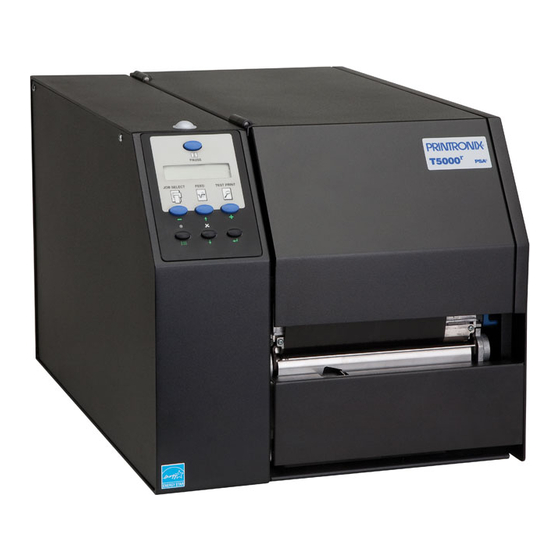
105 P5000 line matrix (pedestal) Figure 85 page 106 SL4M/T4M thermal Figure 86 page 106 SL5000/T5000 thermal Figure 87 page 107 L55XX laser Figure 88 page 107 L1524 laser The layout of the operator panel changes to visually simulate the printer being used (line matrix, thermal, or laser), but the keys and indicators function as described on page 108, regardless of the type of printer used. - Page 105 For More Information Operator Panel Window Status Indicator Secondary Operator Keys Message Display Primary Operator Keys Disabled/In Progress Indicators Figure 83. Line Matrix Printer Virtual Operator Panel (P5000 Cabinet) Operator Panel Window Secondary Operator Keys Message Display Primary Operator Keys Status Indicator Disabled/In Progress Indicators Figure 84.
- Page 106 Chapter Operator Panel Menu/Message Display Operator Keys Disabled/In Progress Indicators Figure 85.Thermal Printer Virtual Operator Panel (SL4M/T4M) Message Display Operator Keys Disabled/In Progress Indicators Figure 86.Thermal Printer Virtual Operator Panel (SL5000/T5000)
- Page 107 For More Information Status Indicator Message Display Secondary Operator Keys Primary Operator Keys Disabled/In Progress Indicators Figure 87. Laser Printer Virtual Operator Panel (L55XX) Message Display Status Indicator Primary Operator Keys Disabled/In Progress Secondary Indicators Operator Keys Figure 88. Laser Printer Virtual Operator Panel (L1524)
-
Page 108: Primary/Secondary Operator Keys
Chapter Operator Panel Primary/Secondary Operator Keys Clicking the primary and secondary operator keys in the operator panel causes the printer to perform the same actions as if you were pressing the keys on the physical operator panel. For example, when the printer is online, click the ONLINE key (line matrix and laser printers) or the (PAUSE) key (thermal printers) to take the printer offline. -
Page 109: In Progress Indicator
In Progress Indicator PRINTER UNDER REMOTE CONTROL appears on the physical operator panel to alert others that the printer is being controlled remotely. However, if someone presses a key on the printer, the virtual operator panel disables. The Disabled indicator lights up, and the Enable button activates. Click the Enable button to give control of the printer back to the virtual operator panel. -
Page 110: File
Chapter Information Capture The following are descriptions of the Information Capture menus. File Save As: Saves the configuration or error log displayed in the Information Capture window as a .txt text file on your local hard drive. This .txt file can be opened in any word processing program. -
Page 111: Directory
Directory Directory Flash File System: Displays the file system information for your printer. NOTE: If your printer is equipped with an EMC (Expanded Memory Cartridge), the files will be displayed in two areas: one for the printer’s internal flash memory, and one for the EMC. See Figure 91. Printer’s Internal Flash... -
Page 112: Autoid Data Manager
Chapter AutoID Data Manager AutoID Data Manager See “AutoID Data Manager” on page 259. ODV Quality Wizard Figure 92. ODV Quality Wizard Window NOTE: You must set the following in the VALIDATOR menu to use the ODV (online data validator) Quality Wizard: •... -
Page 113: Speed Keys
Directory Speed Keys Figure 93. The Speed Keys Window The Speed Keys are single buttons that allow you to perform a specific operation without having to traverse the operator panel menu structure. The Speed Keys assist you in performing repetitive functions associated with printer configuration or maintenance. -
Page 114: Job Capture
Chapter Job Capture Job Capture Figure 94. Job Capture Window Job Capture is an application that captures host datastreams through a specified host interface. This aids in debugging and diagnosing printer errors when working with technical specialists. To access the Job Capture application, select a printer from the printer database and select Applications Job Capture or click the (job capture) button. -
Page 115: Job Capture Features
Job Capture Features Select File Clear Window to clear all capture information from the terminal window. Select File Quit to close the Job Capture application. Job Capture Features File Open Opens a Job Capture file. Save/Save As You can save captured data to disk for later reference or for use in another program. - Page 116 Chapter Job Capture Search Captured Data You can search captured data for specific sequences. Select Search Search Captured Data. Enter the data as a hex or text string. Click OK, and the matching data highlights. To further refine your search, you can choose whether or not to ignore the case, and specify the direction and origin of the search.
- Page 117 Job Capture Features Twinax Host Data • Coax Host Data • C/T Base Emulation • PCI Ethernet In • USB In • NOTE: The USB port is available only on SL5000r/T5000r and SL4M/T4M printers. Triggers Figure 96. Configure Triggers Window A Trigger allows a selective capture of host data.
-
Page 118: Web Access
Chapter Web Access Web Access You can access your printers using a web browser. You can monitor the status, open an operator panel, check the configurations, access Speed Keys, open the ODV Quality Wizard, and access the printer web page. NOTE: To access your printer using a web browser, you must enable the Web Server and XML Server services (see page 28). -
Page 119: Login To The Pne Web Site
Login To The PNE Web Site Login To The PNE Web Site Figure 98. The PNE Web Site By default, three categories of login privileges are available. See Table 6 for a list of categories and their corresponding user names and passwords. Table 6. -
Page 120: The Printer List Page
Chapter Web Access The Printer List Page Figure 101. The Printer List Web Page Click Printer List Page. The Printer List web page appears and lists the same printers found in the database pane. See Figure 101. By default, printers are sorted by Status (Errors). You can also sort printers by Status (Warnings), Status (Online), Address (Ascending), and Address (Descending). -
Page 121: Changing User Settings, Ip Addresses, And Ip Address Ranges
Changing User Settings, IP Addresses, and IP Address Ranges Changing User Settings, IP Addresses, and IP Address Ranges Figure 102. The PpmLogin.xml File The PpmLogin.xml file, located in the PNE installation directory, contains user settings and the included/excluded IP addresses and IP address ranges. See Figure 102. -
Page 122: User Settings
Chapter Web Access User Settings Password Privilege category User name Figure 103. User Login Parameters The user name, password, and privilege category are defined in the <UserDatabase> section of the file. See Figure 103. Password: Defines the password for the designated user name. When you change the password using the Change Password web page, this information updates. - Page 123 Changing User Settings, IP Addresses, and IP Address Ranges IP Addresses and IP Address Ranges Included IP Address Included IP Address Range Excluded IP Address Excluded IP Address Range Figure 104. Include/Exclude IP Address Options You can define which IP addresses are available to PNE for access. Any IP address not included or defined in the included range will be unavailable to PNE.
- Page 124 Chapter Web Access...
-
Page 125: Utilities
Utilities Reboot Printer Reboots the selected printer. Set Printer Password PNE does not allow passwords to change unless the Supervisor password matches the password in the Printer Properties. See “Security Tab” on page 60. NOTE: If a password exists but is unknown, you must clear it first. See “Set Password”... - Page 126 Chapter Set Printer Password To change the printer password: 1. Click the printer name to select it. 2. Select Utilities Set Printer Password. The Change Password dialog box opens. Figure 105. Change Password Dialog Box 3. Type the new password. 4.
-
Page 127: Set Wireless Properties
General Tab Set Wireless Properties NOTE: For a more thorough description of these settings, refer to the Network Interface Card User’s Manual. To set wireless properties, select a wireless printer from the printer database then select Utilities Set Wireless Properties. The Wireless Properties dialog box contains four tabs: General, WEP Encryption, Kerberos, and LEAP. - Page 128 Chapter Set Wireless Properties LEAP is to enable LEAP operation. Kerberos is to enable Kerberos operation. Sub-Channel: Determines the channel for the radio frequency card: 1 through 15 and Default. Transmit Power: Determines the wattage of the transmission power: Max (100 mW - Default), 50% (30 mW), 25% (15 mW), 10% (5 mW), and 1% (1 mW).
-
Page 129: Wep Encryption Tab
WEP Encryption Tab WEP Encryption Tab Figure 107. Wireless Properties: WEP Encryption Tab You must click Read to obtain the printer’s settings before you can modify them. NOTE: If the NIC has a password assigned to the user guest, then a Telnet guest password is required. -
Page 130: Kerberos Tab
Chapter Set Wireless Properties Kerberos Tab The Kerberos tab contains four sub-tabs: Print Server, KDC, Set Password, and Credentials. Figure 108. Wireless Properties: Kerberos Tab – Print Server Sub-Tab Print Server Sub-Tab You must click Read to obtain the printer’s settings before you can modify them. - Page 131 Kerberos Tab Figure 109. Wireless Properties: Kerberos Tab – KDC Sub-Tab KDC Sub-Tab You must click Read to obtain the printer’s settings before you can modify them. NOTE: If the NIC has a password assigned to the user guest, then a Telnet guest password is required.
- Page 132 Chapter Set Wireless Properties Figure 110. Wireless Properties: Kerberos Tab – Set Password Sub-Tab Set Password Sub-Tab You must click Read to obtain the printer’s settings before you can modify them. NOTE: If the NIC has a password assigned to the user guest, then a Telnet guest password is required.
- Page 133 Kerberos Tab Figure 111. Wireless Properties: Kerberos Tab – Credentials Sub-Tab Credentials Sub-Tab This tab displays the Service Principle, the date and time the settings are valid, and the date and time the settings expire.
-
Page 134: Leap Tab
Chapter Set Wireless Properties Figure 112. Wireless Properties: LEAP Tab LEAP Tab IMPORTANT To use LEAP, you must set Authentication to LEAP in the General tab (page 127). ® This tab displays the information necessary for the Cisco LEAP (Lightweight Extensible Authentication Protocol) wireless security scheme. -
Page 135: Wpa Tab
WPA Tab Figure 113. Wireless Properties: WPA Tab WPA Tab This tab displays the information necessary for the WPA (Wi-Fi Protected Access) wireless security scheme. WPA Mode: Selects the WPA wireless security mode. By default the mode is set to Disable thus disabling WPA security. If set to Personal, this selects a personal or pre-shared key mode for WPA security. -
Page 136: Macro Utility
Chapter Macro Utility Macro Utility The Macro Utility allows you to create a series of ten buttons that will do a range of things such as sending a string of text to the printer to performing functions such as form feeds. To access the Macro Utility, click the (macro utility) button at the far right of the toolbar, or select Utilities Macro Utility. -
Page 137: Configure Macro
Configure Macro Configure Macro Figure 115. The Configure Macro Dialog Box To create or edit a macro, click Configure to the right of the macro name (initially 1 through 10). The Configure Macro dialog box opens. See Figure 115. Figure 116. The Print from file Check Box To use a file as a macro, check the Print from file check box. - Page 138 Chapter Macro Utility Figure 117. The Macro String Field You can create a second kind of macro by typing in the Macro String field. The ASCII text appears above, and the hex code below. Use the up and down arrow keys to switch between ASCII text and hex code. Rename the macro in the Macro Name field.
-
Page 139: Snmp Browser
Configure Macro SNMP Browser Figure 119. SNMP Browser The SNMP Browser enables you to view attribute values in the Printer MIB managed by the NIC. You can retrieve an attribute value of a specific MIB Object ID (OID), or you can walk or traverse the MIB. Three inputs are required before you can use the SNMP Browser: 1. -
Page 140: Assign Ip Address
Chapter Assign IP Address Assign IP Address Figure 120. Assign IP Address Allows you to assign IP addresses remotely to NICs that have not been previously configured, or to reconfigure the NIC settings. See Figure 120. IMPORTANT This utility requires expert network knowledge. If you assign incorrect network parameters to the printer, then other devices on the network may operate improperly, possibly causing the whole network to be unusable. -
Page 141: Enable Remote Printer Management
Configure Macro Enable Remote Printer Management This sets the printer’s diagnostic port to Ethernet, without having to navigate through the printer’s operator panel. It performs the following in the background: 1. Opens a command prompt session. 2. Executes a telnet command to the printer’s IP address. 3. -
Page 142: Lock/Unlock Menus
Chapter Lock/Unlock Menus If the following error message appears, then remote printer management has not been enabled. IMPORTANT You may need to set the correct root password. See “Security Tab” on page 60. Figure 123. Remote Printer Management Not Enabled Lock/Unlock Menus Figure 124. -
Page 143: Configure Print Servers
Configure Macro Configure Print Servers Figure 125. Configure Print Servers Window To access the Configure Print Servers application, select one or several printers from the printer database then select Utilities Configure Print Servers or click the Configure Print Servers button. The Configure Print Servers window appears (see Figure 125). - Page 144 Chapter Configure Print Servers...
-
Page 145: Datastream Adapter
Datastream Adapter Overview The datastream adapter is a software filter tool that allows you to take data from an incoming datastream and replace the data with different data, insert new data at any location in the datastream, or flush out portions of the datastream. -
Page 146: Cst Manager
Chapter CST Manager CST Manager Using the CST Manager, you decide which data, as sent by the host, gets modified by the printer. Open PNE and select Applications CST Manager or click the (CST Manager) button to open the CST Manager window. See Figure 127. Menu and Input/Output Fields Toolbar... -
Page 147: The Menu And Toolbar
The Menu And Toolbar The Menu And Toolbar Upload CST Download CST Save Print Copy Delete from printer to printer Paste Open CST Check CSTs for errors Bundle and warnings File New: Closes the current bundle and creates a new one. See “CSTs and CST Bundles”... - Page 148 Chapter CST Manager Tools Test Tests the functionality of the active CST. NOTE: The active CST is the CST currently selected/shown in the CST Manager window. In the left (Input) pane of the Test dialog box, you can open and edit input files or create your own test files.
- Page 149 The Menu And Toolbar Figure 129. Search Dialog Box Available searches are Find, Find Next, and Find Previous. If you select Find, a Search dialog box opens. See Figure 129. Upload Makes a connection to a printer from the printer database, then determines if the printer has a CST file.
- Page 150 Chapter CST Manager 9. In PNE, select Applications Operator Panel. 10. Take the printer offline. 11. Select PRINTER CONTROL Applic. Adapter if you have a thermal printer, or select MAINT / MISC Applic. Adapter if you have a laser or line matrix printer.
-
Page 151: Input/Output Fields
Input/Output Fields Input/Output Fields Figure 130. CST Input/Output Fields These fields allow you to select the appropriate Input/Output sequence. Use Shift + Alt + i and Shift + Alt + o to switch between the Input and Output fields. See “Modes And Attributes” on page 153 for the different Mode selections. Use the four buttons on the right with the Input/Output fields. -
Page 152: The Cst Listing Field
Chapter CST Manager The CST Listing Field Figure 131. CST Listing Field The field below the input and output fields shows the CST. To copy an entry, click it and press Ctrl + C or use the copy button on the toolbar. To move an entry up or down, click it and press Ctrl + up arrow or Ctrl + down arrow. -
Page 153: Modes And Attributes
Modes Modes And Attributes Modes Fourteen modes handle data: Replace, Remove, Insert, Flush, Transparent, Skip GFX Data, Select CST, CST ON, CST OFF, Reset, Response, PAA Event, Store, and Reset All Variables. Each mode allows certain attributes to apply to the characters of the datastream. Common Attributes All modes have four attributes in common: Match, Don’t Care, Don’t Care Except, and Ignore Case. -
Page 154: Transparent Mode
Chapter Modes And Attributes Transparent Mode The Transparent mode allows you to control which data is removed, replaced, or modified. Sometimes the datastream of a graphics file contains a character sequence that is specified in the active CST for removal. If you mishandle this graphics file, important data could be removed. -
Page 155: Store Mode
Modes Response Mode This feature was added to the datastream adapter to allow the definition of a protocol: an interaction between the host computer and the printer that allows the host computer to determine status details of the printer. This allows you to be certain that a job (or label, or form) is completely printed before the next job is sent. -
Page 156: Attributes
Chapter Modes And Attributes Attributes Figure 133. CST: Accessing Attributes To access attributes, right-click any item in the Input field (or select multiple items and right-click). Different attributes are available depending on what mode is selected (see “Modes” on page 153). In the above example, the “s” in “Attributes”... - Page 157 Attributes Ignore Case Allows the matching of characters to be case independent. Whether the character is “X” or “x” a match occurs. Parameter Allows characters in the incoming datastream to have a “label.” You can use this label in the outgoing datastream to move characters to other locations without changing them.
-
Page 158: Additional Features
Chapter Additional Features Additional Features Use Once Flag Entry On/Off Flag Edit Information Patterns / Variables Status Response Definition Figure 134. Additional Features The Use Once Flag This flag, which is set during the entry of a CST, is used when it is impossible to create entries in the table that are unique enough to allow for different outputs according to each of the entries. -
Page 159: The Entry On/Off Flag
The Entry On/Off Flag To reset the used flags: • Append the Reset mode to the CST. • Check the Enable Auto Reset check box in the Edit Information dialog box. See “Edit Information” on page 159. NOTE: The only difference between the two methods is that the Reset mode can be placed anywhere in the CST. -
Page 160: Patterns / Variables
Chapter Patterns / Variables Patterns / Variables Click Patterns / Variables, and the Object Definition dialog box opens. This dialog box is divided into the following tabs: Pattern Character, Pattern, Formatted Pattern, and Variable. When you click OK, the defined set of patterns, pattern characters, formatted patterns, and variables will be available for use by the current bundle. - Page 161 Pattern Character Tab Range: The range of values datastream adapter checks against. NOTE: A continuous interval is separated by two dots, e.g., a..z. Enter hex values with the prefix 0x. To define a continues hex interval, enter 0xNN..0xNN (where NN is a value ranging from 00 to FF). You can define multiple intervals per pattern character by separating the intervals with a , (comma) or a space character.
-
Page 162: Pattern Tab
Chapter Patterns / Variables Edit: Select an item in the Pattern Character List, and click Edit to edit it. NOTE: If you select more than one item, you can only to edit the first item. Remove: Select one or more items in the Pattern Character List, and click Remove to remove them from the list. - Page 163 Pattern Tab Pattern List Lists all the patterns you have defined and added to the list. New: Click New to clear the Name and Pattern fields and create a new pattern. Use a unique and descriptive name. This name appears in pop-up menus when you insert a pattern.
-
Page 164: Formatted Pattern Tab
Chapter Patterns / Variables Formatted Pattern Tab Use the Formatted Pattern tab to add, remove, and edit new and existing formatted patterns. You can use a formatted pattern to identify host data patterns that do not have a fixed length. Figure 138. - Page 165 Formatted Pattern Tab If you use a data pattern character that is not defined as a pattern character, the Don’t Care attribute is always selected. Use the Flush attribute to flush the found data from the host data. Use the Include attribute include the found data in Store operations.
- Page 166 Chapter Patterns / Variables Auto Example: Pattern Character Identifier: # Range: 0..9 Note: Numerals Formatted Pattern Name: fpFieldData Data Pattern: <#> Min: 0 Max: 5 Delimiter: Auto Entry 1 Input: AF;< fpFieldData > Mode: Remove Output: N/A Test Case 1 Host data: ….AF;"12345"….
-
Page 167: How To Use Patterns
How to Use Patterns How to Use Patterns Figure 141. Inserting Patterns in the Input Field Once you define the patterns you can use them in CST entries. To insert a pattern, right-click a character from the input string. Insert Pattern and/or Insert Formatted Pattern displays at the bottom of the pop-up menu. -
Page 168: Pattern Recognition Example
Chapter Patterns / Variables Figure 144. Pattern Screen Tip To see pattern details, i.e., name and definition, hover the pointer over the character in the Input field to display a screen tip. See Figure 144. NOTE: For some Modes, you cannot insert patterns into the Output field. Pattern Recognition Example Normally, the CST only allows you to do an absolute match on a character. - Page 169 Pattern Recognition Example Figure 145. Object Definition: Pattern Character 1. In the CST Manager, click Patterns / Variables. See Figure 145. Next, define the required pattern character by selecting it from the list of available characters. 2. Click the Character down arrow and select 0x23: #. The # character will be used as a label.
- Page 170 Chapter Patterns / Variables Figure 146. Defining a Pattern Character 5. Click Add to add the pattern character to the list. See Figure 146. Next, set up a full pattern using the pattern character just defined. 6. Click the Pattern tab. 7.
- Page 171 Pattern Recognition Example Figure 147. Defining Patterns 13. Click Add to add the pattern to the list. See Figure 147. 14. Click OK to return to the CST Manager.
- Page 172 Chapter Patterns / Variables Figure 148. Selecting the Input Field Now you can use the just defined pattern in the CST. Create an entry in the CST where the input field specifies the thermal printer 1 command sequence bbbb be replaced by the Width pattern and cccc be replaced by the Length pattern.
- Page 173 Pattern Recognition Example Figure 149. Entering the Input String 25. Press the right arrow key, then the down arrow key and type 0A00 (for LF and NUL). See Figure 149. NOTE: The entry in the CST will show “pat” (Pattern) in the attribute field and a pattern number in the character field.
- Page 174 Chapter Patterns / Variables Figure 151. The Appended CST 34. Click Append. See Figure 151. Now you will test the newly created CST. 35. Select Tools Test. The Test window opens. See Figure 152. Figure 152. The Test Window 36. Right-click the Input window. 37.
- Page 175 Pattern Recognition Example Figure 153. Hex Entry Mode 39. Type 1B. To enter the hex equivalent of <ESC>. See Figure 153. Figure 154. Mnemonics Entry Mode 40. Right-click the Input window and select View Mnemonics. To enter the Mnemonics entry mode. Notice the 1B changed to <ESC>. See Figure 154.
-
Page 176: Variable Tab
Chapter Patterns / Variables Variable Tab Use Variable tab to define variables. Use a variable to store data from the host so that it can be used at a later time. To define a variable, enter the name of the variable and add it to the Variable List. To store data into the variable use the Store mode (page 155). -
Page 177: Status Response Definition
Variable Tab Status Response Definition Figure 158. Status Response Generator Click Status Response Definition, and the Status Response Generator dialog box opens. See Figure 158. Use the Status Response Generator to define status responses. You can define printer status bits that make up the condition on which a response should be generated, as well as the details of each response. -
Page 178: Conditions
Chapter Status Response Definition Conditions Use the upper section of the Status Report Generator to add new conditions or select existing conditions to edit or remove. Name: The name of the condition. Output: The response for when the condition is met. Status Bits Unconditional: To create an unconditional protocol. -
Page 179: How To Use Conditions And Protocols
How To Use Conditions And Protocols Interface: Use this drop-down list to select which (host) interface the response should go to. Active is the interface on which the CST operates. Protocol List New: Click New to reset the Name and Interface fields. Add: If the text displayed on the second button is Add, the protocol has not been added to the Protocol list. -
Page 180: Status Response Generator Example
Chapter Status Response Definition Status Response Generator Example A host computer sends out an ENQ character to request the printer’s status. The host computer expects to receive an ACK character when the job has finished, or a NAK character if the printer is printing. In the CST Manager, click Status Response Definition. - Page 181 Status Response Generator Example Figure 161. Switching Between ASCII and Hex Entry Modes 2. Define the output that should be transmitted to the host. In the Output field, press the down arrow key and type 15 (NAK). See Figure 161. NOTE: Use the up and down arrow keys to switch between the ASCII and Hex entry modes.
- Page 182 Chapter Status Response Definition Figure 162. Adding Conditions 8. Click Add to add the entry to the list of protocol conditions. See Figure 162. 9. Name this protocol that is comprised of the two conditions. In the Name field (bottom half of window), type print_complete. 10.
- Page 183 Status Response Generator Example Figure 164. Response Mode Attributes 15. Right-click your input string. A list of possible attributes displays. See Figure 164. NOTE: In addition to the four common attributes, Response mode has the Flush attribute. This attribute removes the input string from the datastream, preventing it from being printed.
-
Page 184: Cst Manager And Ebcdic
Chapter CST Manager And EBCDIC CST Manager And EBCDIC In addition to the standard ASCII character set commonly used for printing, many applications use the EBCDIC character set. The CST Manger is specifically designed to work with ASCII. To work with EBCDIC coded files, characters in the Input and Output strings need to be entered in their EBCDIC representation. - Page 185 Status Response Generator Example EBCDIC Mnemonic Mnemonic ASCII Twinax/LU-1 LU-3 Tape mark “ Device Control 3 Restore Device Control 4 New Line Neg. Acknowledge Back space Synchronous Idle Idle End of Transm. Block Cancel Cancel End of Medium End of Medium Cursor Control Substitute Customer Use 1...
- Page 186 Chapter CST Manager And EBCDIC EBCDIC Mnemonic Mnemonic ASCII Twinax/LU-1 LU-3 Synchronous Idle Three Punch On Four Reader Stop Five Upper Case ¬ Seven Eight Nine Colon Customer Use 3 Semicolon Device Control 4 < Less-than Sign Negative Acknowledge Equal Sign >...
- Page 187 Status Response Generator Example EBCDIC Mnemonic Mnemonic ASCII Twinax/LU-1 LU-3 Logical Or & Ampersand “ ¢ Exclamation Point Dollar Sign Opening Bracket Asterisk Back Slash Right Parenthesis Closing Bracket Semicolon Caret ¬ Logical NOT Underline Minus Sign Grave Accent Slash Comma Percent...
- Page 188 Chapter CST Manager And EBCDIC EBCDIC Mnemonic Mnemonic ASCII Twinax/LU-1 LU-3 Underline > Greater-than Sign Question Mark Colon Number Sign Opening Brace At Sign Vertical Line ‘ Apostrophe Closing Brace Equal Sign Tilde “ Quotation Mark Delete Index Next Line Start of Selected Area End of Selected Area Horz.
- Page 189 Status Response Generator Example EBCDIC Mnemonic Mnemonic ASCII Twinax/LU-1 LU-3 Partial Line Down Partial Line Up Reverse Index Single Shift 2 Single Shift 3 Device Control String Private Use 1 Private Use 2 Set Transmit State Cancel character Message Waiting Start of Protected Area End of Protected Area “...
- Page 190 Chapter CST Manager And EBCDIC EBCDIC Mnemonic Mnemonic ASCII Twinax/LU-1 LU-3 Grave Accent...
- Page 191 Status Response Generator Example EBCDIC Mnemonic Mnemonic ASCII Twinax/LU-1 LU-3...
- Page 192 Chapter CST Manager And EBCDIC EBCDIC Mnemonic Mnemonic ASCII Twinax/LU-1 LU-3 Zero Three Four Five Seven Eight Nine...
-
Page 193: Gpio Manager
GPIO Manager Introduction This chapter describes the Printronix GPIO function available for the Printronix SL5000r/T5000r series Thermal printers. NOTE: Only limited GPIO support is available for Line Matrix printers. Please contact the Customer Support Center for information before ordering Line Matrix printers with GPIO. -
Page 194: Events And Actions
Chapter Events and Actions Events and Actions GPIO operation is based on Events and Actions. Events can be either printer internal such as paper out or print complete, or they can be printer external such as opto-coupler 1 active. Actions are the result of an event and can be printer internal such as paper feed or printer external such as relay 1 active or reply to host where data is transmitted over the serial, parallel, or network interface. -
Page 195: Overview
Overview To launch the GPIO Configuration Manager, select Applications GPIO Manager. The screen in Figure 166 displays. The fields on this screen are described in detail on the following pages. Figure 166. The GPIO Configuration Manager... -
Page 196: The Menus
Chapter Overview The Menus The toolbars allow the handling of files and text. Figure 167. The GPIO Configuration Manager Toolbar File The File menu allows you to create, open, reopen, save a new or existing GPIO program file, or print GPIO configurations. Figure 168. - Page 197 The Menus The Print option allows the mapping table to be printed for later reference. When you select File Print, the GPIO Print Setup dialog box opens allowing you to specify the desired print job. See Figure 169. Figure 169. The GPIO Print Setup Dialog Box...
- Page 198 Chapter Overview When you select File GPIO Configuration the GPIO Configuration dialog box opens. This allows you to define the GPIO properties and power-up settings. Figure 170. The GPIO Configuration Dialog Box The Properties tab allows you to select the type of printer, either Thermal or Impact, for which the mapping table will be designed.
- Page 199 The Menus Figure 171. Power-Up Settings – GPIO Control Tab Within the Power-Up Settings tab are two tabs, GPIO Control and IO. NOTE: Settings made GPIO Control and IO predefining the output levels of GPIO will only be functional when the advanced GPIO features are enabled in the printer.
- Page 200 Chapter Overview NOTE: GPIO does not always acknowledge the PAA trigger. If you use this feature, make sure the event is always acknowledged. Figure 172. Power-Up Configuration – IO Tab, Initial State The Power-Up Settings – IO tab contains two tabs, Initial State and Input Debounce.
- Page 201 The Menus • Relays This section has 8 icons, each representing a single output relay. An active icon means that the relay will be active when the printer is powered on. Click the icon to toggle the state. Figure 173. Power-Up Configuration – IO Tab, Input Debounce Input Debounce When using mechanical switches it is possible that more than one event is generated due to multiple contact detections.
- Page 202 Chapter Overview Edit The Edit menu allows you to define, delete, and rename mapping tables. You can also define data fields and reports to customize a mapping table. New mapping tables can be added to the tables that will be downloaded to the printer and existing mapping tables can be deleted or renamed.
-
Page 203: The Entry Fields
The Entry Fields The Entry Fields Figure 176. The Event To Action Mapping Fields Setting the criteria for mapping tables takes place in the Event to Action Mapping section (see Figure 176). The Description field allows you can enter a descriptive name to indicate the use of the event and its related action. NOTE: The window header indicates which printer type (thermal or line matrix) the mapping table is created for. -
Page 204: Events And Actions
Chapter Overview Figure 178. Setting Action Parameters Events And Actions The Events Table 9 lists the available events and the related parameters. Events parameters are available for the Input Opto-Couplers, Panel Key Pressed events, Printer Error and Warning events (including RFID and ODV related errors), and PAA events (related to Data fields and Timers). - Page 205 Events And Actions Table 9: Events And Parameters Security Key Event Name Description Parameters Required Data Controller Events Start Data Processing Event generated by the printer when None the printer starts processing data. End Data Processing Event generated by the printer when None the printer ends processing data.
- Page 206 Chapter Overview Table 9: Events And Parameters Security Key Event Name Description Parameters Required Job Printed Event generated by the printer when a None jobs is printed. End Paper Move Event generated by the printer when None the printer ends moving the printer. Sensor Event Event generated by the printer when Sensor Type,...
- Page 207 Events And Actions Table 9: Events And Parameters Security Key Event Name Description Parameters Required Table Entered Event generated when a table is None entered or activated. This will be the first event generated when a table is activated with the exception of the power up event.
- Page 208 Chapter Overview “Data Fields” on page 224). This results in 248 different input combinations that can be used to trigger an action. • Printer Powered Up This event is delayed until the moment the printer reaches the Powered- up-online or Powered-up-offline state. The delay is required so the printer can finish its power-on reset cycle before any reaction to an event generates.
- Page 209 Events And Actions • Label Pending This event generates when the printer is in Local mode (i.e., the print engine is temporarily stopped) and all incoming data has been processed. • Started Printing This event happens when the printer starts printing. The printer starts printing when all data processing is done, there is actual data to print, and the printer is no longer in local mode.
- Page 210 The Set state identifies the event when the problem happens. The Cleared state specifies the event when the problem is solved. TOF Detect Fault happens if the T5000 does not find a Top of Form indicator (or a gap) within a specified amount of time after printing starts.
- Page 211 Events And Actions Figure 181. Setting Panel Key Event Parameters • ODV Status This selection allows you to react to output from the ODV (online data validator). The parameters allow you to program GPIO to act if there is no barcode, if there is any or a specific error in the barcode, or when all ODV errors have been cleared.
- Page 212 Chapter Overview • Timer Expired This event happens when a user defined timer expires or when a user defined time is reached. See “Timers” on page 237. • Table Entered This event happens when a new mapping table is entered. The event can be used to execute actions regarding new tables.
- Page 213 Events And Actions Actions The Action field allows you to specify which action should be linked (or mapped) to the selected event. Table 10 lists all possible actions and related parameters. Table 10. Event Actions and Parameters Security Key Action Name Description Parameters Required...
- Page 214 Chapter Overview Table 10. Event Actions and Parameters Security Key Action Name Description Parameters Required Reprint Last Printed Action reprints the last printed None label. Label Form Feed Action performs a form feed. None Move Paper Action moves the paper a Distance to TOF, specified distance in a specified Direction Forward/...
- Page 215 Events And Actions Table 10. Event Actions and Parameters Security Key Action Name Description Parameters Required Beep This action defines the number of Beep Count times the buzzer beeps. Blink This action changes the state of a State, LED/Lamp printer’s led or lamp. General Disable GPIO Events This action prohibits the Event...
- Page 216 Chapter Overview Table 10. Event Actions and Parameters Security Key Action Name Description Parameters Required Performs an action on a user- Timer, Action Timers/RTC defined timer. If no timers are defined, the user is asked to define timers first. Thermal only. Impact only.
- Page 217 Events And Actions • Output Relay The relay number to activate can be specified as well as the level (or state) required for this output. You can select the state by clicking the relay symbol. Pulsed behavior for the relays is equivalent to the pulsed behavior of the opto-coupled outputs.
- Page 218 Chapter Overview • Print Next Label This action can have different functions. If GPIO Print & Apply is enabled, the action is Print Next RFID Label. In Single Label Printing Mode, the action is Print Next Label. If the user switches the printer to Pause mode without going into Single Label Printing Mode, the Print Next Label also functions similar to the previous version of GPIO.
- Page 219 Events And Actions • RFID: Program Next Label This action is specifically designed for RFID Print and Apply applications where the programming of the RFID tag in the label does not have to occur simultaneously with the printing of the actual text on the label. •...
- Page 220 Chapter Overview • Reply to Host The Reply to Host action allows the user to specify a data stream that will transmit to the host when the selected event takes place and to select the interface that should be used for this data transmission. Data entry can be in ASCII or in hexadecimal.
-
Page 221: Entry Control Buttons
Events And Actions Entry Control Buttons The mapping table control buttons are used as follows: • New. Clears the Name field and sets the Event, Action, and related parameters to default. • Add. Adds a new Event-to-Action mapping to the current GPIO program. •... -
Page 222: Multiple Actions
Chapter Entry Control Buttons Multiple Actions If required, GPIO can execute a number of actions on a single event. Multiple actions specified for a single event will be executed in the order they are entered in the mapping table. Figure 189 shows a mapping table where the first action is to enable GPIO events by making the Input Opto-coupler event active. -
Page 223: The On Flag
The ON Flag The ON Flag You can use the On flag to temporarily disable entries in the GPIO mapping table. This is useful if an extensive mapping table is generated with many events leading to the same action. The On flag allows you to test each event reaction separately. -
Page 224: Data Fields
Chapter Data Fields Data Fields Figure 193. The Define Data Fields Dialog Box Data fields are storage locations in the printer’s resident memory. To define a data field, select Edit Define Data Fields. The Define Data Fields dialog box opens (Figure 193). The Name field allows the user to create a data field descriptive to the user’s needs. -
Page 225: Data Field Events And Actions
Data Field Events And Actions Data Field Events And Actions Data Field Actions are used to modify the content of the Data Field which results in an event. An example is provided to better understand how Data Field Actions work in correlation to Data Field Events. - Page 226 Chapter Data Fields Once the data field is defined and added to the list, make sure that the count decrements by one each time a form prints. To set the parameters, use the Label Printed event and the Data Field action. In the Data Field parameter block specify what you want to happen when the event Label Printed occurs.
- Page 227 Data Field Events And Actions Table 11. Operator Data Field Setting Operator Results D = D | S Destination ‘Logical OR’ with Source D = D & S Destination ‘Logical AND’ with Source D = D ^ S Destination ‘Logical EXOR’ with Source D = D &~ S Destination ‘Logical AND’...
-
Page 228: Data Field Events
Chapter Data Fields Figure 197. Generating a Mapping Table Entry Now each time a label or form prints, the value in the data field forms count decrements by one. Next make sure that when the last form prints, a message is sent to the operator panel display as defined by setting a data field event. - Page 229 Data Field Events The Source drop down menu is the data field for which the event is active. The Value field allows you to specify the number you want the Source to be compared. The Condition field indicates when exactly the related action takes place.
-
Page 230: Reports
Chapter Reports The resulting mapping table in Figure 199 allows you to keep track of printed labels. Figure 199. Creating a Forms Counter Entry Reports Reports are messages that can be sent to a number of destinations in the printer. A report is created by specifying one or more sections and by indicating the sequence in which these sections should be combined to form the report. -
Page 231: Defining Reports
Defining Reports Defining Reports Continuing with the previous example, we want to receive a message on the operator panel LCD that all forms have been printed. To define a report do the following: 1. Select Edit Define Reports. The Define Reports dialog box opens with the Report tab active (Figure 200). -
Page 232: Creating Sections
Chapter Reports Creating Sections In continuing with the example, let us define the message as ‘ALL DONE [xxxxx] where xxxxx represents the remaining count. This divides the report in four sections: • # OF LABELS is the header section during printing •... - Page 233 Creating Sections 7. Type ALL DONE [ in the data pane. 8. Click Add. The Header When Done Printing section is added to the Item List pane. 9. Click the New button and type Forms Count in the Name field to define a third section.
-
Page 234: Creating Reports
Chapter Reports Creating Reports We want to generate two reports using the sections just created. One report to generate during printing and the other to generate after printing is complete. The first report, Label Count, is created with two sections: Header While Printing and Forms Count. - Page 235 Creating Reports Figure 205. Adding Sections to a Report 8. Click the New button. 9. Type Label Printing Done in the Name field. 10. Click Header When Done Printing under Available. 11. Hold the Control key and click Label Count and End under Available. 12.
-
Page 236: Using Reports
Chapter Reports Using Reports To make sure the correct report is transmitted to the operator panel LCD, add the following entry to the mapping table. Figure 206. Defining Entries in the GPIO Manager Once the report has been defined and the Send Report action has been selected, the parameter block allows you to specify what is to be done with this report. -
Page 237: Timers
Delay Timer Mode Timers The GPIO Manager allows timers to be used for different purposes. A timer can be programmed to create a delay between an event and an action or it can be programmed to generate an event at a specific time each day or even at a specific day and time each week. - Page 238 Chapter Timers 4. Enter 2 in the MM field under Initial Delay. This specifies a two minute initial delay in which the operator has two minutes to reload ribbon. If the operator is able to change the ribbon and place the printer online within two minutes, the delay timer stops. If the operator is unable to change the ribbon within the two minutes, then the delay timer starts and the printer gives a warning.
-
Page 239: Daily Timer Mode
Daily Timer Mode Daily Timer Mode To generate an event at a specific time each day, use the Daily timer mode. For example, you may want the printer to send a status report to the host system everyday at 12:45 p.m. The status report can include a number of datafields that keep track of paper, ribbon, or number of labels printed, etc. -
Page 240: Weekly Timer Mode
Chapter Timers Weekly Timer Mode To generate an event on a specific time and day, use the Weekly timer mode. In continuing with the previous example, if you want the printer to generate a report to the host printer on certain days of the week at the same time, do the following. -
Page 241: Using Timers
Using Timers Using Timers Figure 211. Using Timers to Activate an Alarm When there is a ribbon error, the “On Ribbon Error” timer starts (Figure 211). First there is a two minute initial delay for the operator to change the ribbon. If the initial delay expires, it generates a timer expired event in which relay 1 activates. -
Page 242: Mapping
Chapter Mapping Once defined, the timer needs to start at power-up. GPIO uses its own timer based on the Real Time Clock. During the day, the data fields are updated for each label printed and each paper jam occurrence. As soon as the timer expires, the daily status report transmits to the printer. -
Page 243: Preloaded Table
They can also be compatible with all the features available on other manufacturers’ external I/O interfaces. This allows easy migration of Printronix T5000e or T5000r printers to new or existing systems. Field interface is accomplished through an industry standard 50-pin D type connector. -
Page 244: Mapping Examples
Chapter Mapping Mapping Examples Indicator Lights Example Imagine a factory floor with a number of printers. Over each printer are mounted lights that are controlled by the GPIO interface. The lights indicate the printer’s status with the following conditions: Green Orange Yellow Light... - Page 245 Mapping Examples The connections made on the printer’s I/O connector are displayed in the diagram below. 34: R1 com 35: R2 com 36: R3 com 37: R4 com 38: R1 NC 39: R2 NC 40: R3 NC 41: R4 NC 42: R1 NO 43: R2 NO 44: R3 NO...
-
Page 246: Protected Printer Example
Chapter Mapping Protected Printer Example To protect the printer’s configuration from being overwritten, disable the operator panel buttons that are not used daily. The Online and Feed buttons should remain active while the rest disabled. The mapping table listed in Figure 216 shows this function. - Page 247 Mapping Examples Panel Selected Label Printing Imagine that the requirement is to print one of three labels without host intervention. To do this, the operator needs to have a selection mechanism at the printer. For this application, store the three labels (PGL files) in the printer. The three labels named label_1, label_2, and label_3 sit in the printer waiting for the ~EXECUTE command.
- Page 248 Chapter Mapping Figure 219. 25 Pin and 9 Pin Serial Connectors Once the PGL files and GPIO mapping table have been downloaded, and the special serial connector is installed on the printer, the printer will print label_1 when the – key is pressed, label_2 when the Feed key is pressed, and label_3 when the + key is pressed.
-
Page 249: Pin Code Protected Printer
Pin Code Protected Printer Pin Code Protected Printer The printer configuration protection described in the example on page 246 requires a special connector to disable GPIO so a service or application engineer can work on the printer without restrictions. The special connector requires one of the inputs to be specifically saved for protection purposes. - Page 250 Chapter Mapping When a key is pressed, the value of the corresponding data field is added to the value in new_pin (which initially contains 0). If the down key is pressed, new_pin now contains 6. If this is not the last (third) entry, the content of new_pin is multiplied by 10 (effectively shifting it over 1 decimal place).
- Page 251 Pin Code Protected Printer Next to the data fields are status reports and information sent to the host if there is an error. The six reports listed in Table 13 need to be generated. Each report only has a single section that may have the same name as the report.
- Page 252 Chapter Mapping Figure 222. Pin_Part_1 Mapping Table If a key is pressed for the first 7 entries, the value of the related data field is added to the new_pin data field, which is multiplied by 10 to shift the content one decimal place over.
- Page 253 Pin Code Protected Printer Figure 224. Pin_Part_3 Mapping Table The Pin_Part_3 mapping table starts with the same seven entries. The value is added to new_pin but this time we do not multiply the value by 10; we now have the complete PIN code. The message displayed depends on the result of the comparison beween the new_pin data field and the pin_number data field.
-
Page 254: Technical Information
Chapter Technical Information Figure 225. Prt_Locked Mapping Table If it is the third try, the event generator timer starts and the Prt_Locked mapping table is selected. In this table we’ll inform the user that the printer is locked by displaying the Printer Locked message on the LCD. We’ll inform the host by sending a message through the interface and disable the operator panel, making it useless until a power cycle has been done. -
Page 255: Relays
Relays provision for mounting resistors, either in the connection between the actual output pin and the collector of the output transistor or from a common connector pin (17) to the collector of the output resistor. See the drawing on page 258. Relays Relays are the NAiS TX type and are 2-Amp high capacity relays with the following basic specifications:... - Page 256 Chapter Technical Information Table 14 : Connector Wiring 1: IP1A 18: OP1C 34:R1CM 2: IP2A 19: OP2C 35:R2CM 3: IP3A 20: OP3C 36:R3CM 4: IP4A 21: OP4C 37:R4CM 5: IP5A 22: OP5C 38:R1NC 6: IP6A 23: OP6C 39:R2NC 7: IP7A 24: OP7C 40:R3NC 8: IP8A...
-
Page 257: Basic Gpio Schematic Diagram
I/O Connector Basic GPIO Schematic Diagram... -
Page 258: Electrical Inputs And Outputs
Chapter Electrical Inputs And Outputs Electrical Inputs And Outputs GPIO Opto-coupled Input Circuit Opto-coupler 4700 Ohm Input voltage range 5..24 VDC GPIO Opto-coupled Output Circuit Pin 17 Opto-coupler Active Low Output Factory installed jumpers Current Limited Output Load Factory Default Configuration User Selectable Configurations... -
Page 259: Autoid Data Manager
AutoID Data Manager Overview NOTE: You can set the AutoID Data Manager to launch automatically when PNE launches. See “Startup Tab” on page 29. The AutoID Data Manager is an application that can collect EPC (electronic product code) telemetry data (stored on Radio Frequency Identification [RFID] tags) from RFID enabled printers and can also simultaneously collect bar code telemetry data (printed on labels) from ODV (online data validator) enabled printers. -
Page 260: Data Validation
Refer to the RFID Labeling Reference Manual. To collect ODV telemetry data, you must set the printer’s Telemetry Path to Network Port. See “Set Telemetry Path (SL5000/T5000 Series Only)” on page 16. To access the AutoID Data Manager application, first select a printer or printers from the Printer Database that have an RFID encoder. -
Page 261: The Menu And Toolbar
The Menu And Toolbar The Menu And Toolbar Create Fixed Formatted Report Collection Create Report for Start Set Report All Printers Collection Parameters Create Report for Remove Printers View Selected Printers Data Add Printers Figure 227. The Menu and Toolbar Printers Start Collection on All Printers: Starts the collection of telemetry data from all printers in the printer list. -
Page 262: Printer List
Chapter Data Validation Printer List When you add a printer, it appears in the printer list. See Figure 228. Figure 228. A Printer Added to the Printer List The AutoID Data Manager application remembers all printers in the printer list, even after you close the application. NOTE: The only way to remove a printer from the printer list is to select it and click the (delete printer) button or select Printers Remove... -
Page 263: Report Generation
Report Generation If you change the Data Capture file name to a name that already exists, the telemetry data stored in the existing file will not be erased. All new telemetry data will be appended to the existing file. NOTE: You cannot change the Data Capture file name while telemetry data is being captured. -
Page 264: Report Parameters
Chapter Data Validation Report Parameters To export the telemetry data to an ASCII file, select a printer or group of printers, and then select either of the Reports options. The AutoID Data Report Parameters dialog box opens. See Figure 231. Data Fields Chosen... -
Page 265: Viewing Telemetry Data
Viewing Telemetry Data Viewing Telemetry Data NOTE: You cannot view telemetry data if the data is being sent to an external database. Data must be read using the database program. See “Telemetry Data Export To 3rd Party Databases” on page 277. To view collected data from a printer, double-click the printer in the printer list (or select the printer and select View Data from Selected Printer). - Page 266 Chapter Data Validation Viewing Detailed Data To view more detailed information about a label, bar code, or RFID tag, double-click the desired item under Identifier in the AutoID Data Viewer window. See Figure 233, Figure 234, Figure 235, and Figure 236. Figure 233.
- Page 267 Viewing Telemetry Data RFID Version 2 Only Figure 236. Detailed RFID Version 2 Tag Data...
- Page 268 Chapter Data Validation Data Fields NOTE: For the correct syntax for using the data field names in databases, see “Data Field Names” on page 285. Over 70 data fields are available that describe bar code or RFID tag telemetry data. The first nine are defined as follows: 1.
- Page 269 Viewing Telemetry Data 6. Failure Code Bar Code This is the hex value assigned for each type of failure, shown below. See “7. Failure Message” on page 270. Failure Code Failure Code Failure Message (Hex) (Binary) 0000 0000 0000 0000 0000 No error 0001 xxxx xxxx xxxx xxx1...
- Page 270 Chapter Data Validation 7. Failure Message Bar Code Failure data is grouped into different types of failure, each of which defines a bar code problem. • Checksum: This occurs when the bar code is not properly encoded with checksum digits. •...
- Page 271 Viewing Telemetry Data It is possible that more than one failure message can be reported in a bar code report. However, the printer can display only one error message at a time. Thus, when multiple failures are detected, only one message displays and the rest are ignored, based on the following failure priority hierarchy.
- Page 272 Chapter Data Validation Other Error Messages • Calibration Warning: In some cases, the validator can determine if it is out of calibration. When this occurs, the validator will communicate this condition as part of a bar code report. This condition is considered a warning and the printer will not stop.
- Page 273 Viewing Telemetry Data Bar Code Data Fields These are the available bar code data fields: Decoded Data Horizontal Position Deviation Vertical Position Symbology Good Scans on Code Letter Grade Total Scans on Code Ref Decode Good Quiet Zones Decodeability Avg Lead QZ In X’s Modulation Avg Trail QZ In X’s...
- Page 274 Chapter Data Validation RFID Version 1 Data Fields These are the available RFID Version 1 data fields: RFID Tag Failure Pre-Checked Sequence Number Retry Number Error Count Tag Type Failed Tag Count Tag Write Count Data Length Raw Data Refer to the RFID Labeling Reference Manual for a description of these fields. RFID Version 2 Data Fields These are the available RFID Version 2 data fields: RFID Tag Failure...
-
Page 275: Xml Report
Viewing Telemetry Data Comma Separated Variable Report The comma separated variable report format can be easily imported into many database and spreadsheet programs. The report consists of a description line (the first line in the report) that contains the names of the fields in the order of the data. Each field is separated by a comma. - Page 276 Chapter Data Validation Standard RFID Text Report The Standard RFID Text Report is a predefined set of RFID data fields written in ASCII text. See Figure 239. Figure 240. Sample Standard RFID Text Report...
-
Page 277: Telemetry Data Export To 3Rd Party Databases
Viewing Telemetry Data Telemetry Data Export To 3rd Party Databases The AutoID Data Manager allows you to export telemetry data to 3rd party databases using the JDBC interface. To export telemetry data, you need to obtain either a JDBC or an ODBC driver from your database vendor. When configured, the 3rd party database opens when the Data Validation Printers List window opens, and closes when the window closes. -
Page 278: Examples Of Property Definitions
Chapter Telemetry Data Export To 3rd Party Databases 4. OdvJdbcDbFields (Database Fields List) This is a comma separated list of database field names that correspond to the fields defined when the database or spreadsheet was created. Any field names in this list must match an AutoID property name. See “Data Field Names”... -
Page 279: Example Exporting Telemetry Data To A Microsoft Access Database
Example Exporting Telemetry Data To A Microsoft Access Database ® Microsoft Access™ OdvJdbcDriver=sun.jdbc.odbc.JdbcOdbcDriver OdvJdbcUrl=jdbc:odbc:odv;UID=odvuser&PWD=odvpassword OdvJdbcDbName=events OdvJdbcDbFields=CaptureDate,FailureCode,DecodedData NOTE: Date is a reserved word in Microsoft Access. Microsoft Excel OdvJdbcDriver=sun.jdbc.odbc.JdbcOdbcDriver OdvJdbcUrl=jdbc:odbc:odv OdvJdbcDbName=[Sheet1$] OdvJdbcDbFields=CaptureDate,FailureCode,DecodedData Example Exporting Telemetry Data To A Microsoft Access Database This example shows how to create an Access database, connect it to the AutoID Data Manager, and have the AutoID Data Manager export captured telemetry data to the database. - Page 280 Chapter Telemetry Data Export To 3rd Party Databases Figure 241. Adding Fields Using Design View in Microsoft Access 5. Name the next three fields CaptureDate, FailureCode, and DecodedData, and define them as Text data types. See Figure 241. NOTE: Beginning with the second field, the field names must match the order of the fields specified in the OdvJdbcDbFields property.
- Page 281 Example Exporting Telemetry Data To A Microsoft Access Database Figure 242. Entering the Data Source Name 12. Type odv in the Data Source Name field. See Figure 242. 13. Click Select to specify the odv database that you created. 14. Click Advanced to specify the username (odvuser) and password (odvpassword) to access the database.
-
Page 282: Exporting Telemetry Data To A Microsoft Sql Database
Chapter Telemetry Data Export To 3rd Party Databases Exporting Telemetry Data To A Microsoft SQL Database Here is the set up for the Microsoft SQL database using ODBC connectivity: 1. Using Notepad, create an AutoID Data Manager properties file named pm.txt that contains the following text: # Microsoft SQL Connection Using ODBC OdvJdbcDriver=sun.jdbc.odbc.JdbcOdbcDriver... -
Page 283: User Fault Generation
Exporting Telemetry Data To A Microsoft SQL Database User Fault Generation User fault generation is a feature that allows 3rd party applications to stop the printing operation and display a sixteen character message on the printer’s operator panel. Using this feature in conjunction with the telemetry data export function allows external programs to implement a closed-loop telemetry data solution. -
Page 284: How To Generate A User Fault
Chapter User Fault Generation How To Generate A User Fault To generate a user fault, the AutoID Data Manager must be running. In addition, a properly formatted XML message must be transmitted to the XML server port defined in the printer database Preferences. The default XML server port is 8081, but since this port number is user configurable, it is important to verify the XML server port number before sending the user fault message. -
Page 285: Data Field Names
Label Data Fields Data Field Names The following is a list and of all available telemetry data fields. The left column lists the names of the data fields as they appear in the Report Parameters window (page 264) and the detailed label, bar code, and RFID telemetry data windows (page 266). -
Page 286: Bar Code Data Fields
Chapter Data Field Names Bar Code Data Fields Table 17. Bar Code Data Fields Name Database Name Decoded Data DecodedData Deviation Deviation Symbology Symbology Letter Grade LetterGrade Ref Decode RefDecode Decodeability Avg DecodeabilityAvg Modulation Avg ModulationAvg Defects Avg DefectsAvg Edge Contrast Avg EdgeContrastAvg Rmin/Rmax Avg RminRmaxAvg... - Page 287 Bar Code Data Fields Table 17. Bar Code Data Fields Name Database Name Vertical Position VerticalPosition Good Scans on Code GoodScansOnCode Total Scans on Code TotalScansOnCode Good Quiet Zones GoodQuietZones Lead QZ in X’s LeadQzInXs Trail QZ in X’s TrailQzInXs Sync State SyncState X Units Times 10...
-
Page 288: Rfid Data Fields
Chapter Data Field Names RFID Data Fields Table 18. RFID Version 1 Data Fields Name Database Name RFID Tag Failure RfidTagFailure Pre-Checked RfidPrechecked Sequence Number RfidSequenceNumber Retry Number RfidRetryNumber Error Count RfidErrorCount Tag Type RfidTagType Failed Tag Count RfidFailedTagCount Tag Write Count RfidTagWriteCnt Data Length RfidDataLength... -
Page 289: A Contact Information
Europe, Middle East, and Africa (31) 24 6489 311 Asia Pacific (65) 6548 4114 http://www.printronix.com/support.aspx Printronix Supplies Department Contact the Printronix Supplies Department for genuine Printronix supplies. Americas (800) 733-1900 Europe, Middle East, and Africa (33) 1 46 25 1900 Asia Pacific... -
Page 290: Corporate Offices
NL-6600 Ad Wijchen The Netherlands Phone: (31) 24 6489489 Fax: (31) 24 6489499 Printronix Schweiz GmbH 42 Changi South Street 1 Changi South Industrial Estate Singapore 486763 Phone: (65) 6542 0110 Fax: (65) 6546 1588 Visit the Printronix web site at www.printronix.com... - Page 291 Index Parameter, 157 Start/End, 157 Access Method sub-tab, 63 Auto delimiter example, 166 Actions, 194, 204, 213 AutoID Data Manager, 259 descriptions, 216 multiple, 222 After attribute, 157 Bar code data fields, 273, 286 Alert Delivery tab, 46 Bar code validation, 259 Alert Log, 46 Basic GPIO Schematic Diagram, 257 Alert, email, 47...
- Page 292 Configure Print Servers, 143 Diagram, Basic GPIO Schematic, 257 Connections tab, 63 Directory, 111 Contact information, 289 Discover Printers, 39 Control panel Discovery See Operator Panel Known Printers, 43 Copy item in database, 33 Polled, 42 Count attribute, 157 Print Server, 40 Create Discovery tab, 40 configurations, 70...
- Page 293 Information tab, 67 Input field, CST, 151 Fault generation, 283 Input/Output fields, 151 Fields, data, 224 Insert item in database, 33 File Download, 83 Insert mode, 153 File menu, printer database, 25 Insert Pattern attribute, 157 Flag, ON, 223 Insert Variable attribute, 157 Flash file download, 83 Installation, 11 Flash File Manager, 79...
- Page 294 View, 34 primary operator keys, 108 Menu Editor, 72 secondary operator keys, 108 Menu tree, 70 SL4M/T4M, 106 Menus, 196 SL5000/T5000, 106 Migration, 75 status indicator, 108 Mode Opto-coupled input circuit, 258 CST Off, 154 Opto-coupled output circuit, 258 CST On, 154...
- Page 295 Macro Settings, 30 Report parameters, telemetry data, 264 Network, 31 Reports, 230 Printer Database, 26 create, 234 Serial, 32 define, 231 Servers, 28 sections, 232 Startup, 29 use, 236 Preloaded Table, 243 Requirements, 11 Primary operator keys, 108 Reset All Variables mode, 155 Print Server Discovery, 40 Reset mode, 154 Print Server sub-tab, 130...
- Page 296 Status Line, 223 Using Timers, 241 Status menu, printer database, 39 Utilities Status Monitoring Properties, 40 Assign IP Address, 140 Status Response Definition, 177 Configure Print Servers, 143 Status Response Definition example, 180 Enable Remote Printer Management, 141 Status update, 50 Lock/Unlock Menus, 142 Store mode, 155 Reboot Printer, 125...
- Page 298 *253130-001* 253130-001B...
Need help?
Do you have a question about the T5000 and is the answer not in the manual?
Questions and answers