Table of Contents
Advertisement
Quick Links
Advertisement
Table of Contents

Related Manuals for Pilz PSENvip RL D P Set

Summary of Contents for Pilz PSENvip RL D P Set
- Page 1 PSENvip RL D P Set Safe camera systems Operating Manual-1001641-EN-09...
- Page 2 Preface This document is the original document. All rights to this documentation are reserved by Pilz GmbH & Co. KG. Copies may be made for the user's internal purposes. Suggestions and comments for improving this documenta- tion will be gratefully received.
-
Page 3: Table Of Contents
Standard protected field mode....................4.5.2 Box bending protected field mode .................... 4.5.3 Back gauge protected field mode ..................... 4.5.4 Box bending with back gauge protected field mode ..............Operating modes during commissioning .................. Operating Manual PSENvip RL D P Set 1001641-EN-09... - Page 4 Enter overrun ..........................Check protective equipment ..................... 7.5.1 Function test of the safety device ..................... 7.5.1.1 Test during initial commissioning ....................82 7.5.1.2 Test after machine modification....................82 7.5.1.3 Regular check ........................... 83 Operating Manual PSENvip RL D P Set 1001641-EN-09...
- Page 5 Requirements of the user program ................... 10.2 Communication with the safety system ..................Technical details ........................11.1 Technical details ........................11.2 Order reference ........................Attachment ..........................12.1 Check list ..........................12.2 EC declaration of conformity..................... Operating Manual PSENvip RL D P Set 1001641-EN-09...
-
Page 6: Introduction
This documentation is intended for instruction and should be retained for future reference. Validity of the documentation This documentation is valid for the product PSENvip RL D P Set. It is valid until new docu- mentation is published. This documentation is valid for the PSENvip from Version 1.0/year of construction 2014. -
Page 7: Definition Of Symbols
It also highlights areas within the text that are of particular import- ance. INFORMATION This gives advice on applications and provides information on special fea- tures. Operating Manual PSENvip RL D P Set 1001641-EN-09... -
Page 8: Overview
Some inputs and outputs are used for communication with the safety system during the system status TEST: Register tool class on safety system Approve tool class for PSENvip LED indicators for Status of OSSDs Operating statuses Adjustment for initial commissioning Tool change Diagnostics Operating Manual PSENvip RL D P Set 1001641-EN-09... -
Page 9: Scope Of Supply
Transmitter Lower tool Detection zone Receiver Upper tool Fig.: Whole system Scope of supply PSENvip RL D P Set: complete set Order reference Description PSENvip RL D P PSENvip receiver, left, with display and dy- namic muting PSENvip T PSENvip transmitter... -
Page 10: Safety
The upward movement of the press is assumed as a safe movement. Use of the PSENvip RL D P Set is only permitted with the automation system PSS 4000 from Pilz. In the PSS 4000 user program, safety functions must be implemented to safe-... -
Page 11: Approvals
So please note the following: You can avoid crushing and trapping of fingers or hands if the workpiece is handled cor- rectly. Wear protective gloves to prevent cuts from edges, corners and ridges. Operating Manual PSENvip RL D P Set | 11 1001641-EN-09... -
Page 12: Correct Handling Of The Workpiece
Correct handling with flat workpieces Grip the metal sheet by the front corners. Thumbs should be on top of the sheet, palms should hold the sheet from below. Fig.: Handling flat workpieces Operating Manual PSENvip RL D P Set | 12 1001641-EN-09... -
Page 13: Categories / Sil
3.1.3 Categories / SIL The PSENvip may only be used with an automation system PSS 4000 from Pilz with SIL 3 of EN 61508 and PL e of EN ISO 13849-1. Please note: To achieve the corresponding category or SIL, the whole system including all safety-related components (parts, devices, user program etc.) must be included in the as-... -
Page 14: Tool Shapes
These tools cannot be safeguarded in compliance with the standards: The front and rear bending lines are not detected by the protected field on the PSENvip. The following safety guideline applies for press brakes with tools in this tool class. Operating Manual PSENvip RL D P Set | 14 1001641-EN-09... - Page 15 Please also note the following guidelines in danger zones in areas that cannot be detected and monitored by the safeguard. Example: Upper tool with a danger zone outside the zone monitored by the PSENvip Fig.: Danger zone in unmonitored zone Operating Manual PSENvip RL D P Set | 15 1001641-EN-09...
-
Page 16: Standards
Machinery Directive 2006/42/EC. Please note that manufacturers and company operators who use the PSENvip are them- selves responsible for agreeing the regulations with the relevant authorities and comply- ing with them. Operating Manual PSENvip RL D P Set | 16 1001641-EN-09... -
Page 17: Use Of Qualified Personnel
In safety-related applications, please comply with the mission time T in the safety-related characteristic data. When decommissioning, please comply with local regulations regarding the disposal of electronic devices (e.g. Electrical and Electronic Equipment Act). Operating Manual PSENvip RL D P Set | 17 1001641-EN-09... -
Page 18: Function Description
Signals from incremental encoders for defining the position and speed External operator elements or signals (foot switch, reset button for reduced protected field or setup mode, E-STOP pushbutton) Other safety devices (safety valves, prefill valve, contactor for E-STOP) Operating Manual PSENvip RL D P Set | 18 1001641-EN-09... - Page 19 Some inputs and outputs on the receiver are also used for communication with the safety system (see section entitled "Communication with the safety system"). If communication is not required, protected field mode can also be controlled directly via the CNC controller. Operating Manual PSENvip RL D P Set | 19 1001641-EN-09...
- Page 20 The protected field is the cross section of the detection zone. It consists of several segments. Fig.: Definitions Key: 1: Light beam bundle 2: Illuminated target area 3: Protected field 4: Detection zone Operating Manual PSENvip RL D P Set | 20 1001641-EN-09...
-
Page 21: Protected Field
Illuminated target area Rear segments Front segments Central segments Workpiece Lower tool Fig.: Protected field definitions The height of the protected field depends on the overrun (see Overrun [ 25]) Operating Manual PSENvip RL D P Set | 21 1001641-EN-09... -
Page 22: Dynamic Muting
The distance to the top edge of the protected field varies according to the length of the overrun. protected field advance measuring field Fig.: Distance of advance measuring field from protected field Operating Manual PSENvip RL D P Set | 22 1001641-EN-09... - Page 23 The signal statuses of the outputs Mute1/Mute2 and OSSD1/OSSD2 when interrupting the protected field by side intervention or interruption of the advance measuring field before reaching the plate are described in section entitled "Standard interrupted press stroke". Operating Manual PSENvip RL D P Set | 23 1001641-EN-09...
-
Page 24: Standard Interrupted Press Stroke
Side intervention with full protected field or reduced protected field during the dy- namic muting Object interrupts the protected field to the side: OSSD1/OSSD2= 1 -> 0 Mute1/Mute2 = 1 Safety system initiates the stop- ping of the press stroke Operating Manual PSENvip RL D P Set | 24 1001641-EN-09... -
Page 25: Overrun
If you enter a lower value for the overrun, the protected field will also be reduced to an unpermitted level. Operating Manual PSENvip RL D P Set | 25 1001641-EN-09... -
Page 26: Description Of The Units
TRM_ON The receiver uses this signal to switch the transmitter's light source on and off. TRM_SYNC The receiver uses this signal to control the intensity of the transmitter's light source. Operating Manual PSENvip RL D P Set | 26 1001641-EN-09... -
Page 27: Receiver
Input to acknowledge that a press stroke is to be performed with a reduced protected field (front and/or rear segments blanked). The protected field mode selected is shown on the receiver's display. Acknowledgement = 0/1 pulse edge via pushbutton: Run selected protected field mode Operating Manual PSENvip RL D P Set | 27 1001641-EN-09... -
Page 28: Outputs
INFORMATION For details of the output behaviour during a press stroke please refer also to the section entitled "System cycle", in this chapter. Operating Manual PSENvip RL D P Set | 28 1001641-EN-09... - Page 29 When wiring an output with capacitance it is essential to note the pulse dur- ation, repetition period and scan time of the power-up test, otherwise the load may switch on unintentionally. Operating Manual PSENvip RL D P Set | 29 1001641-EN-09...
-
Page 30: Led
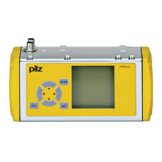
1: OSSD LED 4.4.3.4 Key display and function The PSENvip receiver has an integrated display. Data can be entered via a membrane keypad. PSENvip MODE Fig.: Display on the receiver Operating Manual PSENvip RL D P Set | 30 1001641-EN-09... - Page 31 À Á SYSTEM OK OSSD ON Â NORMAL OPERATION Ã Fig.: Information on the display The display is divided into 4 segments: 1: System status 2: Status of the OSSD Operating Manual PSENvip RL D P Set | 31 1001641-EN-09...
- Page 32 See Chapter 7, "Commissioning" DIAGNOSTICS System data and error codes are displayed in this menu. Pilz tech- nical support can use these to locate errors. See Chapter 9, "Diagnostics and Troubleshooting"...
-
Page 33: Communication With The Safety System
Tool class PSENvip -> PLC Bit 2 X2, 2 PLC Ready X1, 3 Tool class PLC -> PSENvip Bit 1 X1, 4 Tool class PLC -> PSENvip Bit 2 Fig.: Digital inputs and outputs for communication Operating Manual PSENvip RL D P Set | 33 1001641-EN-09... - Page 34 Bit 1 of the tool class. X1, 4 Input Protected field Tool class PLC -> PSEN- The safety system mode 2 vip Bit 2 reflects Bit 2 of the tool class. Operating Manual PSENvip RL D P Set | 34 1001641-EN-09...
- Page 35 Tool class PSENvip -> PLC Bit 2 The PSENvip confirms the validity of the tool class registered on the safety system in step Acknowledge PSENvip -> PLC = 0/1 pulse edge Operating Manual PSENvip RL D P Set | 35 1001641-EN-09...
-
Page 36: Protected Field Modes
– Box bending with back gauge press stroke Use of the protected field modes depends on the tool class. Not all protected field modes can be selected with tool class 2 and 3. Operating Manual PSENvip RL D P Set | 36 1001641-EN-09... -
Page 37: Standard Protected Field Mode
4.5.1 Standard protected field mode The full protected field is available with standard protected field mode. This protected field mode is applied for flat workpieces. Fig.: Standard protected field mode Operating Manual PSENvip RL D P Set | 37 1001641-EN-09... -
Page 38: Box Bending Protected Field Mode
Around the bending line there is an increased risk of crushing and trapping of fingers or hands because the front segments of the protected field are blanked. Make sure that the workpiece is handled correctly (see Chapter "Safety"). Operating Manual PSENvip RL D P Set | 38 1001641-EN-09... -
Page 39: Back Gauge Protected Field Mode
Around the bending line there is an increased risk of crushing and trapping of fingers or hands because the rear segments of the protected field are blanked. Make sure that the workpiece is handled correctly (see Chapter "Safety"). Operating Manual PSENvip RL D P Set | 39 1001641-EN-09... -
Page 40: Box Bending With Back Gauge Protected Field Mode
Around the bending line there is an increased risk of crushing and trapping of fingers or hands because the front and rear segments of the protected field are blanked. Make sure that the workpiece is handled correctly. Operating Manual PSENvip RL D P Set | 40 1001641-EN-09... -
Page 41: Operating Modes During Commissioning
Generally you should not have to mechanically realign the transmitter and receiver during a tool change. In this operating mode The protected field is inactive. The OSSDs are switched off. There is no protection via the PSENvip. Operating Manual PSENvip RL D P Set | 41 1001641-EN-09... -
Page 42: System Cycle
– End: Tool centre point reaches the 6 mm point v = 0 v > 0 Mute 1/2 v < 0 6 mm 6 mm v = 0 Fig.: Definitions Legend: TDC top dead centre Operating Manual PSENvip RL D P Set | 42 1001641-EN-09... -
Page 43: System Cycle For Standard Press Stroke
= 0 System-Init OSSD Protected field Free Mute 1/2 Dynamic muting Inactive Status Downward movement Foot switch System-Init v > 0 OSSD Protected field Free Mute 1/2 Dynamic muting Inactive Operating Manual PSENvip RL D P Set | 43 1001641-EN-09... - Page 44 Foot switch 6 mm 6 mm System-Init OSSD 1 -> 0 Muting of the OSSD in steps 5 to 8 in the safety system Protected field Interrupted Mute 1/2 Dynamic muting Operating Manual PSENvip RL D P Set | 44 1001641-EN-09...
- Page 45 System-Init OSSD 1 or 0 Protected field Free or interrupted Mute 1/2 0 - > 1 Dynamic muting Inactive Continue with step 1 Operating Manual PSENvip RL D P Set | 45 1001641-EN-09...
-
Page 46: System Cycle For Box Bending Press Stroke
Dynamic muting Inactive Status Downward movement Advance measuring field v > 0 touches plate (pinch point) Foot switch System-Init OSSD Protected field Free Mute 1/2 1 -> 0 Dynamic muting Start Operating Manual PSENvip RL D P Set | 46 1001641-EN-09... - Page 47 5 to 8 in the safety system Protected field Interrupted Mute 1/2 Dynamic muting Status Downward movement Foot switch System-Init v > 0 OSSD Protected field Interrupted 6 mm Mute 1/2 Dynamic muting Inactive Operating Manual PSENvip RL D P Set | 47 1001641-EN-09...
-
Page 48: System Cycle For Back Gauge Press Stroke
Acknowledgement of reduced protected field = Press pushbutton and then release The system cycle is the same as for box bending. Please note that with back gauge protec- ted field mode, the rear segments of the protected field are blanked. Operating Manual PSENvip RL D P Set | 48 1001641-EN-09... -
Page 49: System Cycle For Box Bending With Back Gauge Press Stroke
The system cycle is the same as for box bending. Please note that with box bending with back gauge protected field mode, both the front and rear segments of the protected field are blanked. Operating Manual PSENvip RL D P Set | 49 1001641-EN-09... -
Page 50: Installation
– Check the fastening of the PSENvip at regular intervals. – Check that the fastening of the PSENvip is not accidentally working its way loose as a result of vibration from the press brake. Operating Manual PSENvip RL D P Set | 50 1001641-EN-09... -
Page 51: Install Transmitter And Receiver
To install the system, proceed as follows: Fasten the adjustment plate as shown in the diagram below. Ensure that the flat washers, spring washers and nuts are attached in the right order. Operating Manual PSENvip RL D P Set | 51 1001641-EN-09... - Page 52 Viewed from the operator's side, the receiver is installed on the left-hand bracket and the transmitter on the right-hand bracket. Slide the nut slot on the adjustment plate into the groove on the bracket attached to the upper die. Operating Manual PSENvip RL D P Set | 52 1001641-EN-09...
-
Page 53: Dimensions
Installation Dimensions 5.3.1 Transmitter Fig.: Transmitter dimensions, dimensions in mm Operating Manual PSENvip RL D P Set | 53 1001641-EN-09... -
Page 54: Receiver
Installation 5.3.2 Receiver MODE Fig.: Receiver dimensions, dimensions in mm 5.3.3 Fastening kit for the transmitter 97.6 Fig.: Dimensions of the fastening kit for the transmitter, dimensions in mm Operating Manual PSENvip RL D P Set | 54 1001641-EN-09... -
Page 55: Fastening Kit For The Receiver
Installation 5.3.4 Fastening kit for the receiver Fig.: Dimensions of the fastening kit for the receiver, dimensions in mm Operating Manual PSENvip RL D P Set | 55 1001641-EN-09... -
Page 56: Bracket For Transmitter And Receiver
Fig.: Bracket for transmitter and receiver Key: 1: left bracket 2: right bracket 3: 2 x DIN 912 M8x20 cheese head screw 4: adapter plate 5: 4 x DIN 912 M8x20 cheese head screw Operating Manual PSENvip RL D P Set | 56 1001641-EN-09... -
Page 57: Wiring
Earth the cable shield connection within the control cabinet, e.g. on a bus bar. The ready-made cables from Pilz should preferably be used for connecting The PSENvip (see chapter 11, "Technical Details"). Protect the cable from mechanical damage. Lay the cable in such a way that wire short circuits are excluded. - Page 58 When the wiring is complete the protective equipment will need to undergo a function test. INFORMATION To perform the function test, follow the procedure described in Chapter 7, "Commissioning", section entitled "Function test of the safety device". Operating Manual PSENvip RL D P Set | 58 1001641-EN-09...
-
Page 59: Connections
The receiver is connected via two 8-pin cables. Fig.: Receiver's pin assignment The cable ends of the Pilz ready-made cable are colour-coded. Please refer to the tables below for the coding details. Pin assignment of M12 connector X1 on the receiver PIn No. - Page 60 The two safety outputs OSSD1 and OSSD2 must be connected separately to the machine's programmable safety system. OSSD1 and OSSD2 must not be connected. OSSD1 OSSD1 OSSD2 OSSD2 Fig.: Correct and incorrect connection of OSSD1 and OSSD2 Operating Manual PSENvip RL D P Set | 60 1001641-EN-09...
-
Page 61: Transmitter
The top of the transmitter has a 4-pin M12 connector. Fig.: Pin assignment of transmitter The transmitter is connected via a 4-core cable. The cable ends of the Pilz ready-made cable are colour-coded. Please refer to the table below for the coding details. -
Page 62: Connection Diagram
OSSD 2 Mute 2 / Tool class PSENvip -> PLC Bit 2 *) TRM_SYNC *) Used in communication between PSENvip and safety system PSENvip Transmitter TRM_SYNC TRM_ON Fig.: Connection diagram Operating Manual PSENvip RL D P Set | 62 1001641-EN-09... -
Page 63: Commissioning
The vertical and horizontal alignment is performed using adjust- ment templates and is displayed on the receiver. The transmitter and receiver must also be aligned after changing either the PSENvip transmitter or receiver. Operating Manual PSENvip RL D P Set | 63 1001641-EN-09... -
Page 64: Prepare For Alignment
Alignment grid Magnet Back gauge with notch Cross-hair Fig.: Adjustment templates (viewed from the magnet side) You can select either adjustment template to attach to the transmitter or receiver side. Operating Manual PSENvip RL D P Set | 64 1001641-EN-09... -
Page 65: Adjustment Directions Of Transmitter And Receiver
Rotate the screwdriver blade in the required direction. You can use the left or right-hand notch to rotate the transmitter or receiver even further to the left or right. Operating Manual PSENvip RL D P Set | 65 1001641-EN-09... -
Page 66: Align Transmitter
Align the alignment grid of the adjustment template to the contour of the upper tool. Align the alignment grid on the upper tool Centre point of the upper tool in the notch on the back stop Fig.: Attach the adjustment template to the transmitter Operating Manual PSENvip RL D P Set | 66 1001641-EN-09... -
Page 67: Tool Shapes
In the following examples, please note that the maximum width of the respective tools for the tool class can be achieved when the appropriate bending line is used. Examples of the correct adjustment of various tool types: Operating Manual PSENvip RL D P Set | 67 1001641-EN-09... - Page 68 Tool class 3: Stamp The front and rear bending lines of the tool are out- side the protected field. The position of the bending lines must be considered in the hazard analysis. Operating Manual PSENvip RL D P Set | 68 1001641-EN-09...
-
Page 69: Align Receiver
The adjustment image shown in the illustration below will appear on the receiver display. Please note that the bending line is approximately 7 mm to the left of the centre of the dis- play. Fig.: Adjustment image Operating Manual PSENvip RL D P Set | 69 1001641-EN-09... - Page 70 The tool centre point should be aligned with the horizontal guide (the horizontal guide is firmly in the middle of the range bar (see section entitled "Make adjustment during tool change"). Operating Manual PSENvip RL D P Set | 70 1001641-EN-09...
- Page 71 In the case of an invalid adjustment (right-hand diagram), the Out of range message will also appear. Fig.: Checking the adjustment image with superimposed guide frame Operating Manual PSENvip RL D P Set | 71 1001641-EN-09...
- Page 72 (see diagram) 14 mm 20 mm White (maximum protected field) 12 mm 18 mm Blue 10 mm 16 mm Green 8 mm 14 mm Yellow 6 mm 12 mm Brown Operating Manual PSENvip RL D P Set | 72 1001641-EN-09...
-
Page 73: Adjustment Template With Bracket
Fig.: Adjustment template to attach to bracket 1: Ø 3 mm DIN 1472 half length taper-grooved dowel pin 2: M3 x 10 cylinder head bolts 3: Ø 3 mm DIN 1472 half length taper-grooved dowel pin Operating Manual PSENvip RL D P Set | 73 1001641-EN-09... -
Page 74: Adjustment During Tool Change
Transmitter and receiver must be exactly aligned to each other and to the centre point of the upper tool, as described in the section entitled "Initial commissioning". The supply voltage must be present. Operating Manual PSENvip RL D P Set | 74 1001641-EN-09... -
Page 75: Tool Detection
15 mm before the front bending line. Full or partial detection of the upper tool via the protected field. H1 B1 <15 mm >15 mm Fig.: Classification of tools into tool classes Operating Manual PSENvip RL D P Set | 75 1001641-EN-09... - Page 76 The front segments of the protected field are at least 15 mm away from the front bending line. These tools are safeguarded in compliance with the standards. Example: max. 32 mm > 15 mm > 15 mm Fig.: Example for tool class 1 Operating Manual PSENvip RL D P Set | 76 1001641-EN-09...
- Page 77 The front (V3) and/or rear (H3) bending lines are within the protected field. These tools are not safeguarded in compliance with the standards. Example: Fig.: Example for tool class 3 Operating Manual PSENvip RL D P Set | 77 1001641-EN-09...
-
Page 78: Make Adjustment During Tool Change
Press the <MODE> key. Using the keys , select the Tool Change option. Press the <ENTER> key to start the Tool Change. Option 2: Press the ) key to start the Tool Change. Operating Manual PSENvip RL D P Set | 78 1001641-EN-09... - Page 79 The PSENvip prompts you to confirm that you accept the new tool data: Within 3 seconds, press the key You can exit the menu at any time without confirming by pressing <ESC>. In this case, the previous tool data will be retained. Operating Manual PSENvip RL D P Set | 79 1001641-EN-09...
-
Page 80: Enter Overrun
, 4. The menu for entering the overrun will appear. INFORMATION The PSENvip will need to be restarted if the entry - Was invalid - Took longer than 10 s. Operating Manual PSENvip RL D P Set | 80 1001641-EN-09... -
Page 81: Check Protective Equipment
They help to maintain a safe, working condition, i.e. to prevent accidents. The test of the protective equipment consists of: A function test using the test piece a visual inspection Operating Manual PSENvip RL D P Set | 81 1001641-EN-09... -
Page 82: Function Test Of The Safety Device
Changing the PSENvip or swapping PSENvip components should also be regarded as a modification. You must comply with the requirements of the applicable national regulations. Operating Manual PSENvip RL D P Set | 82 1001641-EN-09... -
Page 83: Regular Check
Transmitter and receiver are correctly aligned (see "Initial commissioning"). The press brake is at top dead centre. Transmitter and receiver are ready for operation. Standard protected field mode is selected. Operating Manual PSENvip RL D P Set | 83 1001641-EN-09... -
Page 84: Function Test Using The Test Piece
Function test with 10 mm and 15 mm test piece Position the 10 mm high section of the test piece on top of the lower tool. Initiate a press stroke. Fig.: Function test using test piece Operating Manual PSENvip RL D P Set | 84 1001641-EN-09... -
Page 85: Visual Inspection
Check the following on the PSENvip transmitter and receiver The condition of the installation and attachment Any damage on the housing and lens Electrical connections Switch on the machine. Check the messages on the display. Operating Manual PSENvip RL D P Set | 85 1001641-EN-09... -
Page 86: Operation
SYSTEM OK OSSD ON NORMAL OPERATION Fig.: Display after power-up 8.2.2 Muting lamp Muting lamps warn of residual hazards associated with the safeguard. Operating Manual PSENvip RL D P Set | 86 1001641-EN-09... -
Page 87: Initial Press Stroke
Make sure that the workpiece is handled correctly. An acknowledgement button must be operated to initiate a press stroke with a reduced pro- tected field. Operating Manual PSENvip RL D P Set | 87 1001641-EN-09... -
Page 88: Tool Change
Cleaning the front lenses The front lenses on the transmitter and receiver should be cleaned at regular intervals, us- ing an alcohol glass cleaner. NOTICE Never use aggressive solvents or abrasive cleaning agents! Operating Manual PSENvip RL D P Set | 88 1001641-EN-09... - Page 89 Remove any heavier dirt without scratching the front lens. Carry out a function test using the test piece. See Chapter 7, "Commissioning", section entitled "Function test of the safety device". Operating Manual PSENvip RL D P Set | 89 1001641-EN-09...
-
Page 90: Diagnostics And Troubleshooting
In this state it is possible to make adjustments during initial commissioning and after a tool change. Remedy Note the error message (see section entitled "Error messages"). Rectify the error. Press the <ESC> key and return the PSENvip to the NORMAL OPERATION state. Operating Manual PSENvip RL D P Set | 90 1001641-EN-09... -
Page 91: Major Errors
Restart the PSENvip: Switch supply voltage off and then on again. The error message will not be displayed. However, it will be possible to select the DIA- GNOSTICS menu. Note the error message (see section entitled "Error messages"). Contact Pilz. Operating Manual PSENvip RL D P Set | 91 1001641-EN-09... -
Page 92: Error Messages
No valid data detected (tool and/ and/or overrun) adjustment during tool change or overrun) No adjustment performed 1.) Make adjustment during tool No adjustment performed after after tool change change tool change Operating Manual PSENvip RL D P Set | 92 1001641-EN-09... - Page 93 Repeat tool change Repeat tool change adjust- adjustment 2.) Remove any dirt on the tool ment INFORMATION Please contact Pilz if none of the suggested remedies are able to rectify the error. Operating Manual PSENvip RL D P Set | 93 1001641-EN-09...
-
Page 94: Diagnostics Menu
Diagnostics and Troubleshooting DIAGNOSTICS menu The DIAGNOSTICS menu provides Pilz service staff with further information to help them identify faults. Press the <MODE> key. Using the keys , select the DIAGNOSTICS menu. Press the <ENTER> key to open the DIAGNOSTICS menu. - Page 95 Press the <MODE> button to access the next diagnostic block. Press the keys to access the diagnostic data within a diagnostic block. Exit the DIAGNOSTICS menu using the <ESC> key. Operating Manual PSENvip RL D P Set | 95 1001641-EN-09...
-
Page 96: System Connections
System Connections 10.1 Requirements of the user program The automation system PSS 4000 from Pilz is required to run PSENvip. In the PSS 4000 user program the following safety functions must be implemented to safeguard the dynamic muting of PSENvip: Monitoring of the pinch point –... - Page 97 The switchover point must be raised in comparison with the regular switchover point. The switchover to lower speed must take place earlier. The user program must convey a higher switchover point to the CNC controller and then monitor this. Operating Manual PSENvip RL D P Set | 97 1001641-EN-09...
- Page 98 : SAFEBOOL; // Tool value Bit 1 from PSS4000 TypeA2 END_VAR RisingFlagE0 : R_TRIG; // FUNCTION block rising edge for Signal RisingFlagE1 : R_TRIG; // FUNCTION block rising edge for Signal bComEnd : BOOL; // End of communication Operating Manual PSENvip RL D P Set | 98 1001641-EN-09...
- Page 99 => bToolValidFlag bToolValidFlag bToolValid // Waiting for the tool valid signal from PSENvip bToolValid JMPC END // Tool NOT Valid ANDN bToolTypeE2 ANDN bToolTypeE3 JMPC END // Tool class 01 bToolTypeE2 Operating Manual PSENvip RL D P Set | 99 1001641-EN-09...
- Page 100 UINT#2 uiToolTypePSENvip ENDDATATRANSFER: // Comparing the tool value between PSENvip and CNC uiToolTypePSENvip uiToolTypeCNC JMP END // Waiting for the end of communication bStartToolChangeE0 bValidToolChangeE1 bToolTypeE2 bToolTypeE3 bComEnd Operating Manual PSENvip RL D P Set | 100 1001641-EN-09...
- Page 101 System Connections bComEnd JMPC END RESTORE: FALSE bAcknowledgeToolChangeA0 bAcknowledgeToolTypeA1 bAcknowledgeToolTypeA2 TRUE bStartCom bToolValid END: END_FUNCTION_BLOCK Operating Manual PSENvip RL D P Set | 101 1001641-EN-09...
-
Page 102: Technical Details
24 VDC Tolerance range 20 V … 30 VDC including residual ripple of max. ± 1.2 V Current consumption Max. 2 A at 24 VDC Connection type 2 x M12, 8-pin Operating Manual PSENvip RL D P Set | 102 1001641-EN-09... - Page 103 -35 ℃ … 70 ℃ (EN 60068-2-1, EN 60068-2-2) Climatic suitability 93 % rel. h. at 40 °C (EN 60068-2-78) Condensation Not permitted Vibration Frequency range: 10 Hz … 55 Hz Operating Manual PSENvip RL D P Set | 103 1001641-EN-09...
- Page 104 PL e (Cat. 4) Cat. 4 SIL CL 3 5.08E-9 (T = 40 °C) All the units used within a safety function must be considered when calculating the safety characteristic data. Operating Manual PSENvip RL D P Set | 104 1001641-EN-09...
-
Page 105: Order Reference
Technical details 11.2 Order reference Order reference: PSENvip RL D P Set Designation Order no. PSENvip RL D P Set 583 007 Complete PSENvip set Order reference: Accessories Designation Order no. PSENvip RL D P 583 601 PSENvip receiver with display... - Page 106 PSEN op cable axial M12 8-p. screening 30 630 328 Straight plug, 8-pin, screened, 30 m for re- ceiver The names of products, goods and technologies used in this manual are trademarks of the respective companies. Operating Manual PSENvip RL D P Set | 106 1001641-EN-09...
-
Page 107: Attachment
Make sure that there are no transparent materials between the transmitter and receiver (e.g. glass panel). Are all the mechanical connections to the PSENvip attached correctly? Cables are undamaged? Operating Manual PSENvip RL D P Set | 107 1001641-EN-09... - Page 108 Check protected field modes Do the protected field modes operate in accordance with the setting of the operating mode selector switch? Date: ………………………………………… Signature: ……………………………………………………………… Operating Manual PSENvip RL D P Set | 108 1001641-EN-09...
-
Page 109: Ec Declaration Of Conformity
Attachment 12.2 EC declaration of conformity Operating Manual PSENvip RL D P Set | 109 1001641-EN-09... - Page 110 We are represented internationally. Please refer to our homepage www.pilz.com for further details or contact our headquarters. Headquarters: Pilz GmbH & Co. KG, Felix-Wankel-Straße 2, 73760 Ostfildern, Germany Telephone: +49 711 3409-0, Telefax: +49 711 3409-133, E-Mail: info@pilz.com, Internet: www.pilz.com...
Need help?
Do you have a question about the PSENvip RL D P Set and is the answer not in the manual?
Questions and answers