Sign In
Upload
Manuals
Brands
Omron Manuals
Servo Drives
R88M-K1K520T
Omron R88M-K1K520T Manuals
Manuals and User Guides for Omron R88M-K1K520T. We have
1
Omron R88M-K1K520T manual available for free PDF download: User Manual
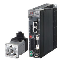
Omron R88M-K1K520T User Manual (438 pages)
AC SERVOMOTORS/SERVO DRIVES WITH BUILT-IN EtherCAT COMMUNICATIONS
Brand:
Omron
| Category:
Servo Drives
| Size: 16.86 MB
Table of Contents
Items to Check after Unpacking
14
Revision History
15
Structure of this Document
16
Table of Contents
18
Chapter 1 Features and System Configuration
26
Outline
26
Outline of the OMNUC G5 Series
26
Features of OMNUC G5-Series Servo Drives
26
What Is Ethercat
27
Object Dictionary
27
System Configuration
28
Names and Functions
29
Servo Drive Part Names
29
Servo Drive Functions
30
System Block Diagram
31
Applicable Standards
32
EC Directives
32
UL and Cul Standards
32
Functional Safety
32
Chapter 2 Models and External Dimensions
34
Servo System Configuration
34
How to Read Model Numbers
36
Servo Drive
36
Servomotors
37
Model Tables
38
Servo Drive Model Table
38
Servomotor Model Tables
39
Servo Drive and Servomotor Combination Tables
41
Cable and Peripheral Device Model Tables
43
External and Mounting Dimensions
52
Servo Drive Dimensions
52
Servomotor Dimensions
58
External Regeneration Resistor Dimensions
69
EMC Filter Dimensions
70
Chapter 3 Specifications
72
Servo Drive Specifications
72
General Specifications
72
Characteristics
73
Ethercat Communications Specifications
76
Main Circuit and Motor Connections
77
Ethercat Communications Connector Specifications (RJ45)
79
Control I/O Connector Specifications (CN1)
80
Control Input Circuits
83
Control Input Details
84
Control Output Circuits
86
Control Output Details
87
Encoder Connector Specifications (CN2)
90
External Encoder Connector Specifications (CN4)
90
Monitor Connector Specifications (CN5)
94
USB Connector Specifications (CN7)
95
Safety Connector Specifications (CN8)
96
Overload Characteristics (Electronic Thermal Function)
98
Overload Characteristics Graphs
98
Servomotor Specifications
99
General Specifications
99
Characteristics
100
Encoder Specifications
112
Cable and Connector Specifications
113
Encoder Cable Specifications
113
Motor Power Cable Specifications
115
Connector Specifications
120
Ethercat Communications Cable Specifications
123
Analog Monitor Cable Specifications
126
Control Cable Specifications
128
External Regeneration Resistor Specifications
133
External Regeneration Resistor Specifications
134
EMC Filter Specifications
135
Chapter 4 System Design
138
Installation Conditions
138
Servo Drive Installation Conditions
138
Servomotor Installation Conditions
139
Decelerator Installation Conditions
142
Wiring
143
Peripheral Equipment Connection Examples
143
Main Circuit and Motor Connections
146
Wiring Conforming to EMC Directives
151
Wiring Method
151
Selecting Connection Component
155
Regenerative Energy Absorption
169
Calculating the Regenerative Energy
169
Servo Drive Regeneration Absorption Capacity
171
Regenerative Energy Absorption with an External Regeneration Resistor
172
Connecting an External Regeneration Resistor
173
Chapter 5 Ethercat Communications
176
Display Area and Settings
176
Node Address Setting
176
Status Indicators
177
Structure of the CAN Application Protocol over Ethercat
178
Ethercat State Machine
179
Process Data Objects (Pdos)
180
PDO Mapping Settings
180
Sync Manager PDO Assignment Settings
181
Fixed PDO Mapping
181
Service Data Objects (Sdos)
182
Abort Codes
182
Synchronization with Distributed Clocks
183
Communications Cycle (DC Cycle)
183
Response Time
183
Emergency Messages
184
Chapter 6 Drive Profile
186
Controlling the State Machine of the Servo Drive
186
State Machine
186
Modes of Operation
189
Cyclic Synchronous Position Mode
190
Block Diagram for Position Control Mode
192
Torque Limit
193
Related Objects
193
Touch Probe Function (Latch Function)
194
Related Objects
194
Trigger Signal Settings
194
Fully-Closed Control
197
Outline of Operation
197
Objects Requiring Settings
198
Parameter Block Diagram for Fully-Closed Control Mode
203
Object Description Format
205
Communication Objects
206
PDO Mapping Objects
212
Sync Manager Communication Objects
214
Manufacturer Specific Objects
218
Servo Drive Profile Object
221
Reserved Objects
237
Connecting with OMRON Controllers
238
Related Objects
238
Chapter 7 Applied Functions
240
Sequence I/O Signals
240
Input Signals
240
Output Signals
243
Forward and Reverse Drive Prohibition Functions
245
Objects Requiring Settings
245
Overrun Protection
248
Operating Conditions
248
Objects Requiring Settings
248
Operation Example
249
Backlash Compensation
250
Objects Requiring Settings
250
Brake Interlock
252
Objects Requiring Settings
252
Operation Timing
253
Electronic Gear Function
257
Objects Requiring Settings
257
Operation Example
259
Torque Limit Switching
260
Operating Conditions
260
Objects Requiring Settings
260
Gain Switching Function
262
Objects Requiring Settings
263
Gain Switching
264
Diagrams of Gain Switching Setting
266
Gain Switching 3 Function
269
Operating Conditions
269
Objects Requiring Settings
269
Operation Example
270
Chapter 8 Safety Function (Application Pending)
271
Safe Torque off Function
272
I/O Signal Specifications
273
Operation Example
275
Connection Examples
277
Chapter 9 Details on Servo Parameter Objects
280
Basic Settings
280
Gain Settings
285
Vibration Suppression Settings
294
Analog Control Objects
300
Interface Monitor Settings
303
Extended Objects
311
Special Objects
317
Reserved Objects
329
Chapter 10 Operation
332
Operational Procedure
332
Preparing for Operation
333
Items to Check before Turning on the Power Supply
333
Turning on the Power Supply
334
Checking the Displays
335
Absolute Encoder Setup
337
Setting up an Absolute Encoder from the CX-Drive
337
Trial Operation
338
Preparations for Trial Operation
338
Test Operation Via USB Communications from the CX-Drive
339
Chapter 11 Adjustment Functions
342
Analog Monitor
342
Objects Requiring Settings
342
Gain Adjustment
345
Purpose of the Gain Adjustment
345
Gain Adjustment Methods
345
Gain Adjustment Procedure
346
Realtime Autotuning
347
Objects Requiring Settings
348
Setting Realtime Autotuning
348
Setting Machine Rigidity
349
Manual Tuning
354
Basic Settings
354
Damping Control
356
Outline of Operation
356
Objects Requiring Settings
356
Adaptive Filter
359
Objects Requiring Settings
360
Operating Procedure
361
Notch Filters
362
Objects Requiring Settings
363
Disturbance Observer Function
365
Operating Conditions
365
Objects Requiring Settings
366
Operating Procedure
366
Friction Torque Compensation Function
367
Operating Conditions
367
Objects Requiring Settings
367
Operation Example
368
Hybrid Vibration Suppression Function
369
Operating Conditions
369
Objects Requiring Settings
369
Operating Procedure
369
Feed-Forward Function
370
Objects Requiring Settings
370
Operating Procedure
371
Instantaneous Speed Observer Function
373
Operating Conditions
373
Objects Requiring Settings
373
Operating Procedure
374
Chapter 12 Troubleshooting and Maintenance
376
Troubleshooting
376
Preliminary Checks When a Problem Occurs
376
Precautions When a Problem Occurs
377
Replacing the Servomotor or Servo Drive
377
Errors
382
Immediate Stop Operation at Errors
386
Troubleshooting
388
Troubleshooting with Error Displays
388
Troubleshooting Using the Operation State
400
Periodic Maintenance
406
Servomotor Life Expectancy
406
Servo Drive Life Expectancy
407
Replacing the Absolute Encoder Battery
408
Object List
412
Ethercat Terminology
430
Index
430
Advertisement
Advertisement
Related Products
Omron R88M-K1K520H
Omron R88M-K1K520H-S2
Omron R88M-K1K520T-S2
Omron R88M-K1K520F
Omron R88M-K1K520F-S2
Omron R88M-K1K520C
Omron R88M-K1K520C-S2
Omron R88M-K1K520H-B
Omron R88M-K1K520H-BS2
Omron R88M-K1K520T-B
Omron Categories
Blood Pressure Monitor
Controller
Accessories
Switch
Inverter
More Omron Manuals
Login
Sign In
OR
Sign in with Facebook
Sign in with Google
Upload manual
Upload from disk
Upload from URL