
Related Manuals for YOKOGAWA ADMAG AXR


Summary of Contents for YOKOGAWA ADMAG AXR
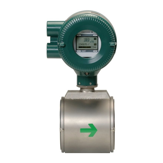
- Page 1 User’s Manual Two-wire Magnetic Flowmeter Integral Flowmeter [Style:S2] IM 01E30D01-01EN IM 01E30D01-01EN 8th Edition...
-
Page 2: Table Of Contents
BASIC OPERATING PROCEDURES (USING THE DISPLAY UNIT) ....5-1 5.1 Operating Panel Configuration and Functions ..........5-2 Display Unit Setting Methods ................5-3 5.2.1 Display Mode → Setting Mode ............5-3 5.2.2 Setting Mode ..................5-5 8th Edition: April 2020 (KP) IM 01E30D01-01EN All Rights Reserved, Copyright © 2009, Yokogawa Electric Corporation... - Page 3 Toc-2 Parameter Setting Procedure ................5-5 5.3.1 Setting Example for Selection-Type Data: Flow rate units ....5-5 5.3.2 Setting Example for Numeric-Type Data: Flow rate span ....5-7 5.3.3 Setting Example for Alphanumeric-Type Data: Tag number ..... 5-8 PARAMETER DESCRIPTION ..............6-1 Parameters......................
- Page 4 Toc-3 8.8.5 Switching HART Protocol Revision ........... 8-6 8.8.6 Other operations for the HART configuration tool ......8-7 Menu Tree for DD (HART 5) ................8-8 8.10 Menu Tree for DTM (HART 5) ................. 8-13 OPERATION VIA HART CONFIGURATION TOOL (HART 7) ....9-1 HART Protocol Revision .................. 9-1 9.2 Device Description (DD) on a HART Configuration Tool and AXR Device Revision ..................
- Page 5 Toc-4 OUTLINE ....................12-1 12.1 STANDARD SPECIFICATIONS ..............12-1 12.2 HAZARDOUS AREA CLASSIFICATION ............12-5 12.3 STANDARD PERFORMANCE ................ 12-6 12.4 NORMAL OPERATING CONDITIONS ............12-8 12.5 MODEL AND SUFFIX CODE ................12-9 12.6 OPTIONAL SPECIFICATIONS ..............12-13 12.7 EXTERNAL DIMENSIONS ................12-16 12.8 SIZING DATA (Measurable flow velocity is from 0 m/s.) ......12-23 PED (PRESSURE EQUIPMENT DIRECTIVE) ........
-
Page 6: Introduction
When describing the model name like • If the customer or any third party is harmed by AXRC in this manual, “” means any the use of this product, Yokogawa assumes of the following. no responsibility for any such harm owing to 025, 040, 050, 065, 080, 100, 150, 200 any defects in the product which were not predictable, or for any indirect damages. -
Page 7: Using The Magnetic Flowmeter Safely
<1. INTRODUCTION> Using the Magnetic CAUTION Flowmeter Safely A CAUTION sign denotes a hazard. It calls (1) Installation attention to procedure, practice, condition or the like, which, if not correctly performed or adhered WARNING to, could result in damage to or destruction of part or all of the product. - Page 8 Yokogawa. (7) Modification • Care should be taken to prevent the build up of dirt, dust or other substances on the Yokogawa will not be liable for malfunctions or display panel glass or name plate. If these damage resulting from any modification made surfaces do get dirty, wipe them clean with a to this instrument by the customer.
-
Page 9: Warranty
• Problems that result from using or performing maintenance on the instrument in a location that does not comply with the installation location specified by Yokogawa. • Problems or damage resulting from repairs or modifications not performed by Yokogawa or someone authorized by Yokogawa. • Problems or damage resulting from inappropriate reinstallation after delivery. • Problems or damage resulting from disasters such as fires, earthquakes, storms, floods, or lightning strikes and external causes. IM 01E30D01-01EN... -
Page 10: Atex Documentation
<1. INTRODUCTION> ATEX Documentation This is only applicable to the countries in European Union. IM 01E30D01-01EN... -
Page 11: Handling Precautions
• A place subject to minimal vibrations or Be sure you have your model number and serial shocks number available when contacting Yokogawa. • Temperature and humidity levels should be as follows: Temperature: -30 to 70°C Humidity: 5 to 80% RH (no condensation) The preferred ambient temperature and humidity levels are 25°C and... -
Page 12: Installation Location Precautions
<2. HANDLING PRECAUTIONS> Installation Location Precautions Select the installation location with consideration to the following items to ensure long-term stable operation of the instrument. Ambient Temperature: Avoid installing the instrument in locations with constantly fluctuating temperatures. If the location is subject to radiant heat from the plant, provide heat insulation or improve ventilation. -
Page 13: Installation
<3. INSTALLATION> INSTALLATION Piping Design Precautions When installing two or more magnetic flowmeter on a single pipe, provide a run of at least 5D between them. WARNING D: Flowtube Size Gate valve Reducer Expander Installation of the magnetic flowmeter must fully open pipe pipe be performed by expert engineer or skilled personnel. No operator shall be permitted to 5 D or more 2 D or more 0 is allowable 0 is allowable... - Page 14 <3. INSTALLATION> (5) Precautions for Use of Liquid Sealing (9) Mounting Positions Compounds • Pipes must be fully filled with liquids. IMPORTANT IMPORTANT Care must be taken in using liquid sealing If the pipe is empty, the output fluctuates or the compounds on the piping, as it may have a Process Alarm (Signal Overflow) occurs. The negative influence on the flow indications by pipe must be fully filled with liquid. flowing out and covering the surfaces of an electrode or grounding ring. In particular, care Piping shall be designed so as to maintain the must be taken if a liquid sealing compound is interior of the flowtube filled with fluids.
-
Page 15: Handling Precautions
<3. INSTALLATION> Handling Precautions • Mounting orientation IMPORTANT WARNING Install the magnetic flowmeter so that the The magnetic flowmeter is a heavy instrument. electrodes position is not perpendicular to the Be careful that no damage is caused to ground. Otherwise it may cause the measuring personnel through accidentally dropping it, or errors because air bubbles at upper side or slurry by exerting excessive force on the magnetic at downside covers the electrode. -
Page 16: Flowmeter Piping
<3. INSTALLATION> 3.2.2 Flowmeter Piping (4) Terminal Box Cover IMPORTANT CAUTION As it is possible that the insulation will Misaligned or slanted piping can lead to leakage deteriorate, do not open the terminal box cover and damage to the flanges. until it is time to wire it. (1) Correct any misaligned or slanted piping, and (5) Long-term Non-use any gaps that may exist between mounting... -
Page 17: Mounting Procedures
<3. INSTALLATION> Mounting Procedures (2) Mounting Centering Devices To maintain concentricity of the flowmeter with the NOTE pipes, install centering devices on the Mini-flanges of the flowmeter. Use the appropriate centering • The tightening torque value to which gaskets devices according to the nominal diameter and the must be tightened varies depending on the flange ratings. type and external dimensions of the lining and the gasket. In this section, the tables (3) Positioning the Flowmeter indicating tightening torque values include Pass two through-bolts through the adjacent holes... - Page 18 <3. INSTALLATION> *Nut (eight units) *: These items can be ordered optionally. *Through-bolt (four units) If they are provided by the user, choose nuts and bolts in compliance with the flange ratings. Piping-side flange Centering device (two units) Mini-flange Horizontal mounting F0308b.ai *Gasket (two units) F0308a.ai...
- Page 19 <3. INSTALLATION> Table 3.3.3 Wafer Type Tightening Torque Values for Metal Piping and Permeable Fluids Tightening torque values for PFA lining type (N-m / {kgf-cm} / [in-lbf]) Gasket types No gasket (standard) within flowtube Gasket types for user’s PTFE-sheathed non-asbestos gasket (optional code BSF), or the equivalent in hardness flange Flange ratings Size JIS 10K, ANSI Class 150, and DIN PN10 JIS 20K, ANSI Class 300, and DIN PN16...
- Page 20 <3. INSTALLATION> (4) Tightening Nuts CAUTION Tighten the nuts according to the torque values for metal piping in Table 3.3.4. For PVC piping, select For a flowmeter with fluorocarbon PFA lining, an optional code of GA, GC, or GD, use rubber it is possible that the nuts may loosen as time gaskets and tighten the nuts to the torque values for passes, so tighten them regularly.
- Page 21 <3. INSTALLATION> Table 3.3.5 Wafer Type Tightening Torque Values for PVC Piping Tightening torque values for PFA lining type Unit: {kgf-cm} [in-lbf] Gasket types Fluororubber gasket (optional codes GA, GC, and GD) within flowtube Gasket types Fluororubber gasket, chloroprene rubber gasket (optional code BSC), or the equivalent in hardness for user’s flange Flange ratings ANSI Class...
-
Page 22: Flange Type
3-10 <3. INSTALLATION> Table 3.3.8 Centering Device Identification (AXR Lay length code 2, PFA lining) Flange ANSI ratings Size PN10 PN16 PN40 (75M) mm (inch) 50 (2.0) — — — 65 (2.5) — — — 80 (3.0) — — 100 (4.0) — — 150 (6.0) — — 200 (8.0) — *: Each centering device is engraved with a character as identification. - Page 23 3-11 <3. INSTALLATION> *Piping-side flange *Gasket (two units) *: These items must be provided by the user. Choose nuts and bolts in compliance with the flange ratings. Flowmeter-side flange *Bolt *Nut F0310.ai Figure 3.3.3 Mounting Procedure for Flange Type (size: 25 mm (1.0 in.) to 200 mm (8.0 in.)) Table 3.3.9 Flange Type Tightening Torque Values for Metal Piping Tightening torque values for PFA lining type...
- Page 24 3-12 <3. INSTALLATION> Table 3.3.10 Flange Type Tightening Torque Values for PVC Piping Tightening torque values for PFA lining type Unit: {kgf-cm} [in-lbf] Gasket types Fluororubber gasket (optional codes GA, GC, and GD) within flowtube Gasket types Fluororubber gasket, chloroprene rubber gasket, or the equivalent in hardness for user’s flange Flange ratings ANSI Class...
-
Page 25: Gaskets Size
3-13 <3. INSTALLATION> 3.3.4 Gaskets Size Lay length code 2; Unit: mm (in.) PFA lining Be sure to choose a gasket with an inner and outer Wafer diameter that does not protrude inside the piping. Recommended Inner If the inner diameter of the gasket is too large, Diameter of Gasket Outer or outer diameter of the gasket is too small, fluid... -
Page 26: Wiring
<4. WIRING> WIRING Wiring Precautions This section describes the wiring of the integral flowmeter. Be sure to observe the following precautions when wiring: WARNING CAUTION The wiring of the magnetic flowmeter must be performed by expert engineer or skilled • Do not connect cables outdoors in wet personnel. No operator shall be permitted to weather in order to prevent damage from perform procedures relating to wiring. -
Page 27: Terminal Configuration And Terminal Wiring
<4. WIRING> 4.2 Terminal Configuration and Wiring Ports Terminal Wiring This instrument is of watertight construction as stipulated in JIS C0920. It is shipped with a wiring Terminal bracket (waterproof gland or waterproof gland with Description Symbols ➀ union) or a plastic gland attached, only in cases Functional grounding ➀... - Page 28 <4. WIRING> For working on the electric wire tubes or the flexible (3) Conduit Wiring tubes (G1/2), remove the waterproof gland and When wiring the conduits, pass the conduit attach them directly to the wiring port. through the wiring connection port, and utilize the waterproof gland to prevent water from flowing in. Place the conduit pipe on an angle as shown in Figure 4.3.4.
-
Page 29: Grounding Connection
<4. WIRING> Grounding Connection IMPORTANT • In case of General-purpose Use, grounding resistance of 100 Ω or less is necessary. When the optional code A is selected, Class A grounding grounding resistance of 10 Ω or less shall be terminal required. • In case of TIIS explosion proof type, Grounding grounding resistance of 10 Ω or less is terminals necessary for class A grounding terminal. Grounding resistance of 100 Ω or less is necessary for Functional grounding terminal. When the optional code A is selected, grounding resistence of 10 Ω or less is F0408.ai necessary for Functional grounding terminal. - Page 30 <4. WIRING> [General - purpose Use/Explosion Proof Type IMPORTANT except TIIS] Class A grounding should be installed in non- 600 V vinyl-insulated cable (2 mm or larger) hazardrous area. Grounding ring • Class D requirements (grounding resistance, 100 Ω or less). Optional code A (lightning protector): Class C requirements (grounding resistance, 10 Ω...
-
Page 31: Wiring Connections
<4. WIRING> Wiring Connections The description of the terminal symbols is shown in Table 4.5.1. (1) Removing Cover Table 4.5.1 Terminal Symbols The cover has the locking screws in front and No. Terminal Symbols Description behind it as shown in Figure 4.5.1 in case of Functional grounding ➀... -
Page 32: Wiring Procedure
TIIS explosion proof type. The ADMAG AXR can be connected with almost all distributors, signal conditioner cards, and I/O modules except certain devices. Read the Table 4.6.1 for Yokogawa’s devices, Power supply choose an appropriate connecting device and the cable corresponding length of cable. - Page 33 <4. WIRING> Table 4.6.1 Connecting device and Applicable maximum cable length (guideline) Maximum length of cable Connecting device E−14.7 (rough guideline) 0.0236 Digital Cable Cable Communication External with cross with cross Range Name Model Load (BRAIN or HART) section of section of Resistance 2 mm...
- Page 34 <4. WIRING> Selection of HART 5/ HART 7 IMPORTANT Output Signal Code Ordering Precaution for Pulse Output – Specify “5” Specify “7” Information • As this is a transistor contact (insulated HART Protocol HART 5 HART 7 type), give attention to proper voltage and Revision polarity when wiring. Be sure to • Do not apply a voltage larger than 30 V DC confirm the...
- Page 35 4-10 <4. WIRING> NOTE Precaution for Pulse Output For pulse output from the DO terminal, parameters must be set. Read Chapter 6 in this manual. NOTE Precaution for Status Output and Alarm Output For status output and alarm output from the DO terminal, parameters must be set.
- Page 36 4-11 <4. WIRING> Wiring Examples (General - purpose Use/Explosion Proof Type except TIIS) Table 4.6.2 Current Output, Pulse Output, Status Output and Alarm Output (General - purpose Use/Explosion Proof Type except TIIS) Connection Description Current Output R3[Ω]:Load Resistance AXR Terminal In this case, Distributor, etc. Communication is Cable Resistance:R1[Ω] � possible SUPPLY Cable Resistance:R2[Ω] − (up to a distance of 2 −...
- Page 37 4-12 <4. WIRING> Table 4.6.3 Simultaneous Current-Pulse Output (General - purpose Use/Explosion Proof Type except TIIS) Connection Description Simultaneous Current- When simultaneous output of current and pulse output are used, no communication is possible Pulse Output in some cases. Read the following example 1 to 3. Example 1 0.0236 x (R1 + R2+ R3) + 14.7 ≤ E1 [V] ≤ 42 In this case, In the case of R3=250[Ω] Communication is...
- Page 38 4-13 <4. WIRING> Table 4.6.4 Digital External Indicator Using Current Output (General - purpose Use/Explosion Proof Type except TIIS) Connection Description Current Output Digital External Indicator 77.7% Example 1 Connection to digital external indicator V2: Voltage between terminals of External Indicator AXR Terminal Relaying terminal Distributor, etc. R3[Ω]: Cable Resistance:R2[Ω] Cable Resistance:R1[Ω] SUPPLY Load Resistance Cable Resistance:R4[Ω] Transmission of AXR...
- Page 39 4-14 <4. WIRING> WIRING EXAMPLE (TIIS Explosion Proof Type) Table 4.6.5 Current Output, Pulse Output, Status Output and Alarm Output (TIIS Explosion Proof Type) Connection Description Current Output Hazardous area Non-hazardous area In this case, AXR Terminal JIS Class A Communication is Distributor, etc.
- Page 40 4-15 <4. WIRING> Connection Description Status Output Hazardous area Non-hazardous area Alarm Output 42 *10 ≤ ≤ In this case, 0.0236×﴾R1 R2﴿ 14.7 AXR Terminal No communication is JIS Class A possible when a four- Cable Resistance:R1[Ω] wire cable is used. SUPPLY Cable Resistance:R2[Ω]...
- Page 41 4-16 <4. WIRING> Connection Description Example 3 Hazardous area Non-hazardous area ≤ ≤ 0.0236×﴾R1 R2﴿ 20.6 In this case, No communication is Recorder possible when a four- or other − instrument wire cable is used. 250Ω AXR Terminal JIS Class A Cable Resistance:R1[Ω] SUPPLY...
- Page 42 4-17 <4. WIRING> Table 4.6.7 Digital External Indicator Using Current Output (TIIS Explosion Proof Type) Connection Description Current Output Transmission of AXR Hazardous area Non-hazardous area Digital External Indicator output might fail when Example 1 77.7% the external indicator Connection to digital breakdown occurs.
-
Page 43: Basic Operating Procedures (Using The Display Unit)
<5. BASIC OPERATING PROCEDURES > (USING THE DISPLAY UNIT) BASIC OPERATING PROCEDURES (USING THE DISPLAY UNIT) Both of four push button and magnet switches can CAUTION be used for setting. The magnet switches can be used to set parameters without opening the case Precautions for Push Button Switches cover. -
Page 44: Operating Panel Configuration And Functions
<5. BASIC OPERATING PROCEDURES > (USING THE DISPLAY UNIT) Operating Panel (1) Data display area Configuration and Functions 1st line (Display Select1), 2nd line (Display Select2) and 3rd line (Display Select3) can (4) Reversed (1) Data display area be displayed using parameter settings. The character display content corresponding to selected items is... -
Page 45: Display Unit Setting Methods
<5. BASIC OPERATING PROCEDURES > (USING THE DISPLAY UNIT) Display Unit Setting Methods NOTE Before changing any settings, be sure to check the corresponding setting details in Chapter 6. 5.2.1 Display Mode → Setting Mode Display Mode will be adopted when the power is turned on, and the Setting Mode can be activated using the following procedure. -
Page 46: Setting Mode
<5. BASIC OPERATING PROCEDURES > (USING THE DISPLAY UNIT) A screen is displayed to confirm whether or not the system is to enter Setting Mode. (*1) Entry Mode Press the switch and select [Yes]. Setting mode The reversed-character (i.e. the cursor position) indicates the item that is currently selected. /SHIFT NOTE (*1) -
Page 47: Parameter Setting Procedure
<5. BASIC OPERATING PROCEDURES > (USING THE DISPLAY UNIT) 5.2.2 Setting Mode When the Setting Mode has been activated using the procedure from Subsection 5.2.1, parameters can be selected for setting. NOTE If no operations are carried out for a period of 10 minutes in Setting Mode, the system will automatically return to the Display Mode. - Page 48 <5. BASIC OPERATING PROCEDURES > (USING THE DISPLAY UNIT) Sub-item Parameter Search Mode has been Major item B:Easy Setup Sub-item accessed in this screen. 50:Auto Zero Exe Parameter Sub-item Touch the switch to move the cursor to B21: 10:Language parameter Search Mode 20:Flow Damping Base Flow Unit.
-
Page 49: Setting Example For Numeric-Type Data: Flow Rate Span
<5. BASIC OPERATING PROCEDURES > (USING THE DISPLAY UNIT) 5.3.2 Setting Example for Numeric-Type Data: Flow rate span This example describes the setting of the flow rate span for the numeric-type parameter B23: Flow Span from 100 l/min to 120 l/min. Setting Mode Condition Setting mode Setting mode Start: P:Protect Major item Major Item Touch the SET switch to access B: Easy Setup. -
Page 50: Setting Example For Alphanumeric-Type Data: Tag Number
<5. BASIC OPERATING PROCEDURES > (USING THE DISPLAY UNIT) When the switch is touched, the entire display flashes on and off. Confirm that the setting B23:Flow Span 120 l/min has been correctly changed to “120,” and then fix this value by touching the SET switch once again. NOTE When no operations are carried out for 20 seconds in the flashing state, the system will automatically return to the Sub-item Parameter Search Mode. - Page 51 <5. BASIC OPERATING PROCEDURES > (USING THE DISPLAY UNIT) Upon selection of C: Basic Setup, the cursor will Major item C:Basic Setup be positioned at C10: Tag No. (Sub-item selection Sub-item 49:Flow User Span Sub-item Parameter screen (C)) 10:Tag No selection (C) Search Mode 11:Flow Damping...
-
Page 52: Parameter Description
<6. PARAMETER DESCRIPTION> PARAMETER DESCRIPTION Parameters NOTE With the exception of parameters that were specified by the customer upon ordering, all In order to ensure that correct flow rate data can of the internal parameters will initially be set to be acquired, it is crucial that the nominal size, default values. Actions such as the modification of flow rate span, and meter factor of the combined display details can then be carried out whenever flowtube are set. When the AXR integral necessary. -
Page 53: Parameter List Overview
<6. PARAMETER DESCRIPTION> Parameter List Overview (1) Item A (Menu A): Display items Menu A contains the instantaneous flow rate, totalization values, and other items relevant to display. Name Data range Position Default value Item R/W Units of decimal Description Display unit Display unit (*): Indicated item point (BRAIN) /BRAIN A00 Display (DISPLAY) A10 FR -103.1 to 103.1 For Display Mode only (FLOW RATE (%)) - Page 54 <6. PARAMETER DESCRIPTION> Name Data range Position Default value Item R/W Units of decimal Description Display unit Display unit (*): Indicated item point (BRAIN) /BRAIN B22 Base Time Unit /s (*) Selects time units for the flow (TIME UNIT) /min rate span. Linked with C41. B23 Flow Span 0.00001 to 32000 B21/B22...
- Page 55 <6. PARAMETER DESCRIPTION> (3) Item C (Menu C): Basic Setting items Menu C principally contains the basic setting items for the flowtube. Name Data range Position Default value Item R/W Units of decimal Description Display unit Display unit (*): Indicated item point (BRAIN) /BRAIN C00 Basic Setup (BASIC SETUP) C10 Tag No ASCII 16 or ASCII 8 Sets Tag number up to 16 or 8 (TAG NO)
- Page 56 <6. PARAMETER DESCRIPTION> Name Data range Position Default value Item R/W Units of decimal Description Display unit Display unit (*): Indicated item point (BRAIN) /BRAIN C43 Flow Decimal Pnt Auto Auto (*) Selects decimal point (FLOW DECIMAL) position for the display unit’s instantaneous flow rate. Linked with B24.
- Page 57 <6. PARAMETER DESCRIPTION> (4) Item D (Menu D): Total Setting items Menu D contains setting items such as the totalization scale and the forward/reverse totalized values. Name Data range Position Default value Item R/W Units of decimal Description Display unit Display unit (*): Indicated item point...
- Page 58 <6. PARAMETER DESCRIPTION> (5) Item E (Menu E): Pulse Setting items Menu E contains items relevant to pulse output. This is used to set parameters such as the pulse scale and width. Name Data range Position Default value Item R/W Units of decimal Description...
- Page 59 <6. PARAMETER DESCRIPTION> (6) Item F (Menu F): Status Functions Setting items Menu F contains items relevant to multiplex range output and other status Output. Name Data range Position Default value Item R/W Units of decimal Description Display unit Display unit (*): Indicated item point (BRAIN)
- Page 60 <6. PARAMETER DESCRIPTION> (7) Item G (Menu G): Alarm Setting items Menu G contains setting items relevant to alarm output, burnout, alarm record, etc. Name Data range Position Default value Item R/W Units of decimal Description Display unit Display unit (*): Indicated item point (BRAIN)
- Page 61 6-10 <6. PARAMETER DESCRIPTION> Name Data range Position Default value Item R/W Units of decimal Description Display unit Display unit (*): Indicated item point (BRAIN) /BRAIN G42 Alm Record Time1 0D 00:00 to Displays the operation time (ALM TIME 1) 9999D 23:59 at the occurrence of the most recent alarm.
- Page 62 6-11 <6. PARAMETER DESCRIPTION> (8) Item H (Menu H): Display Setting items Menu H contains setting items that are relevant to display on the display unit. Name Data range Position Default value Item R/W Units of decimal Description Display unit Display unit (*): Indicated item point...
- Page 63 6-12 <6. PARAMETER DESCRIPTION> (9) Item J (Menu J): Auxiliary Function Setting items Menu J contains setting items such as the flow direction, rate limits, and low cut. Name Data range Position Default value Item R/W Units of decimal Description Display unit Display unit (*): Indicated item point (BRAIN) /BRAIN J00 Aux (AUX) J10 4-20mA Low Cut 0 to 20 Sets the range in vicinity of 0% (4-20 LOW CUT)
- Page 64 6-13 <6. PARAMETER DESCRIPTION> (10) Item K (Menu K): Diagnostic Function Setting items Menu K contains items that are relevant to the diagnosis of insulation adhesion to the electrode. Name Data range Position Default value Item R/W Units of decimal Description Display unit Display unit...
- Page 65 6-14 <6. PARAMETER DESCRIPTION> (11) Item M (Menu M): Automatic Zero-Adjustment Function Setting items Menu M contains items that are relevant to automatic zero adjustment. Name Data range Position Default value Item R/W Units of decimal Description Display unit Display unit (*): Indicated item point (BRAIN)
- Page 66 6-15 <6. PARAMETER DESCRIPTION> (13) Item P (Menu P): Parameter Protection items Menu P contains items that are relevant to write protection and passwords. Name Data range Position Default value Item R/W Units of decimal Description Display unit Display unit (*): Indicated item point (BRAIN)
-
Page 67: Parameter Description
6-16 <6. PARAMETER DESCRIPTION> Parameter Description [B20: Flow Damping] Setting of the damping time constant → This setting is linked with that of parameter C11. IMPORTANT The damping time constant should be modified to suppress an output fluctuation or to change the One output can be selected from pulse, alarm, or response time. This time constant has an effect status through the parameter setting. - Page 68 6-17 <6. PARAMETER DESCRIPTION> [B24: Flow Decimal Pnt] Setting of the decimal NOTE point position for the instantaneous flow rate → This setting is linked with that of parameter C43. If the flow rate units, time units, and flow This parameter sets the position of the decimal rate span are specified upon ordering, these point for instantaneous flow rate values in terms parameters will be setup before shipment; of the number of digits.
- Page 69 6-18 <6. PARAMETER DESCRIPTION> [B30: Total Unit] Setting of units for totalization • The totalized units are indicated on the scale display unit when B31/D11 is 0.00001, → This setting is linked with that of parameter D10. 0.0001, 0.001, 0.01, 0.1, 1, 10, 100, 1000, This parameter selects the flow rate units for use in or 10000. In the case of other setting values, totalization.
- Page 70 6-19 <6. PARAMETER DESCRIPTION> [B33: Pulse Scale] Setting of pulse scale [B40: Display Select1] Setting of the first line for → This setting is linked with that of parameter E11. display unit Pulse output is performed in individual counts in → This setting is linked with that of parameter H10. accordance with this parameter’s setting.
- Page 71 6-20 <6. PARAMETER DESCRIPTION> (2) Menu C: Basic Setting items [C22: Low MF (IEM)] Setting of the low-frequency meter factor (Excitation current (Middle)) Menu C principally contains the basic setting items This parameter sets the low-frequency meter factor for the flowtube. as required for excitation current (Middle). NOTE [C23: High MF (IEM)] Setting of the high-frequency meter factor (Excitation current (Middle))
- Page 72 6-21 <6. PARAMETER DESCRIPTION> [C41: Base Time Unit] Selection of time units for [C51: Flow User Unit] Setting of the special flow the flow rate span rate units → Read the description of parameter B22. This parameter is used to select the special units (up to maximum 8 characters in length). These [C42: Flow Span] Setting of the flow rate span units are displayed when instantaneous flow rate →...
- Page 73 6-22 <6. PARAMETER DESCRIPTION> (3) Menu D: Total Setting items NOTE Menu D contains parameters that are relevant to totalization function settings. When the low cut is small, an incorrect output may occur at the flow rate of zero and the [D10: Total Unit] Setting of units for totalization totalization may be carried out.
- Page 74 6-23 <6. PARAMETER DESCRIPTION> [D22: Ttl Set Val Upper] Setting of the totalization NOTE preset value (upper 2 digits) This parameter sets a totalization preset value in Example: To count in 1 dl (deci-liter) steps with the upper 2 digits of the 8-digit totalized value. If flow rate span=10 l/s.
- Page 75 6-24 <6. PARAMETER DESCRIPTION> Data Range NOTE Pulse Rate (pps) Setting When the low cut is small, an incorrect output Maximum Value Minimum Value may occur at the flow rate of zero and a (0) 50% Duty 11000 0.0001 (pps: pulses per pulse may be output. Use the instrument with (1) 0.05ms 10000 second)
- Page 76 6-25 <6. PARAMETER DESCRIPTION> (5) Menu F: Status Function Setting items Menu F contains setting items relevant to status Output functions. [F10: DO Function] Setting of the function for the DO output terminal This parameter sets the function for the DO (digital output) terminal. Setting Function Description...
- Page 77 6-26 <6. PARAMETER DESCRIPTION> Parameter setting sequence NOTE (for automatic multiple ranges switching) Multiple ranges setting F10: DO Function Select a function. Parameters from F20 to F31 are used with the automatic multiple ranges. The followings will describe the setting method for the range. F11: DO Active Mode Select whether DO output is to be “Closed (On) Act”...
- Page 78 6-27 <6. PARAMETER DESCRIPTION> (6) Menu G: Alarm Setting items NOTE Menu G principally contains setting items relevant For more details regarding the setting of to alarms. (Read Section 6.5.) hysteresis width, read the description of setting parameter for F30: Auto Range Hys and F31: [G10: Low Alarm] Low alarm setting Bi Direction Hys.
- Page 79 6-28 <6. PARAMETER DESCRIPTION> Output Example 2 [G12: H/L Alarm Hys] Setting of upper/lower alarm The high alarm (H) is set to 80% or more of the flow value hysteresis width rate span only without low alarm (L) setting; and the This parameter sets the hysteresis width for upper H/L alarm hysteresis width is set to 0%. and lower alarm value, using a % value of the Settings are: maximum span.
- Page 80 6-29 <6. PARAMETER DESCRIPTION> [G25: 4-20mA Process Alarm] Selection of the [G28: Alm-H/L] Alarm recognition of “H/L Alarm” current output during a process alarm occurrence This parameter specifies whether H/L alarm in This parameter sets the current output during a process alarms will be recognized as an alarm. process alarm occurrence.
- Page 81 6-30 <6. PARAMETER DESCRIPTION> [G31: Alarm setting] Selection of the alarm output [G41: Alm Record1] Alarm record1 during a setting error occurrence This parameter is used to display the most-recent This parameter specifies whether the alarm will alarm, and the alarms that can be displayed are as be recognized as an alarm during a setting error follows.
- Page 82 6-31 <6. PARAMETER DESCRIPTION> [G42: Alm Record Time1] Display the operation (7) Menu H: Display Setting items time of alarm record1 Menu H contains setting items relevant to the This parameter is used to display the operation time display unit. at which the alarm indicated by G41: Alm Record1 was occurred.
- Page 83 6-32 <6. PARAMETER DESCRIPTION> (8) Menu J: Auxiliary Function Setting items NOTE Menu J contains setting items such as the flow direction, rate limits, and current output limits. The default setting is 3%. When the low cut is small, an incorrect output [J10: 4-20mA Low Cut] Setting of the low-cut may occur at the flow rate of zero. Use the range for current output instrument with the default setting 3%.
- Page 84 6-33 <6. PARAMETER DESCRIPTION> [J15: Pulse Special Mode] Selection of the pulse NOTE special mode This parameter is used to set the pulse mode only • If the setting value for the low limit is not less instead of using current output. than the high limit value (as set using J12: 4- Setting Function...
- Page 85 6-34 <6. PARAMETER DESCRIPTION> [J22: Dead Time] Setting of dead time (3) Since input signals do not return to within This parameter sets the time for application of the the rate limit value during the dead time, it is rate limit, and if a value of 0 is set, the rate limit determined at (c) that this signal is a flow rate function will be terminated.
- Page 86 6-35 <6. PARAMETER DESCRIPTION> [J30: Basic Frequency] Selection of the basic (9) Menu K: Diagnostic Function Setting items frequency Menu K contains items that are relevant to the This parameter is changed from default setting as diagnosis of insulation adhesion to the electrode “Freq (1)” to “Freq (2)” if the magnetic flowmeter and so on.
- Page 87 6-36 <6. PARAMETER DESCRIPTION> [K16: Adhesion Level4] Setting the resistance IMPORTANT value for adhesion diagnosis level4 This parameter sets the resistance value (in M • Parameters cannot be set during execution ohm) for judgment of Level 4. (approximately 5 minutes). *: The process alarm as 33:Adhesion Alm is displayed if “Yes” is • Adhesion diagnosis should only be carried selected at G29:Alm-Adhesion, and the value is beyond the out when the fluid velocity is completely zero...
- Page 88 6-37 <6. PARAMETER DESCRIPTION> [K21: DC Voltage A] Display of the voltage level at IMPORTANT electrode A This parameter is used to display the DC voltage • If the pipe is empty, the output fluctuates or level at electrode A. The possibility of adhesion at the Process Alarm (Signal Overflow) occurs. the electrode A is higher when this value becomes The pipe must be fully filled with liquid.
- Page 89 6-38 <6. PARAMETER DESCRIPTION> [M13: Flow Zero(IEM)] Display of the result of (11) Menu N: Loop Test Setting items automatic zero adjustment (excitation current Menu N contains items that are relevant to loop (Middle)) testing. This parameter is used to display the result of automatic zero adjustment (excitation current [N10: Test Mode] Setting for loop test execution (Middle) at B50(M10): Auto Zero Exe.
- Page 90 6-39 <6. PARAMETER DESCRIPTION> [N15: Test Time] Selection of the holding time of [N40: Average Execution] Selection of execution test mode for measurement of averaged flowrate This parameter is used to select the holding time of This parameter is used to select whether the test mode from the last operation in test mode.
- Page 91 To obtain the joker password, please contact your nearest P21:Enable Wrt Passwd YOKOGAWA sales office. F0617.ai The cursor will flash when entering Parameter Replacement Mode, and the password set with P22: New Password should be input at this time.
-
Page 92: Alarm Functions
6-41 <6. PARAMETER DESCRIPTION> Alarm Functions 6.5.2 Alarm Selection The display and output differs depending on the 6.5.1 Alarm Levels alarm levels. Certain types of alarm may or may not be recognized as alarms, according to the settings Alarms are classified into the following four different of certain parameters. The parameters that are types based on level. - Page 93 6-42 <6. PARAMETER DESCRIPTION> (1) Display and output condition for system alarms Alarm 4-20mA Alarm Alarm description Totalization Pulse Display unit output output record Normal Closed Normal Normal Normal Display Mode (ON) 10 μP Fault Microprocessor Open Fixed at Indetermination Indetermination Indetermination Indetermination (CPU) failure...
- Page 94 6-43 <6. PARAMETER DESCRIPTION> (3) Display and output condition for setting alarm occurrences Selection Alarm 4-20 mA Pulse Alarm (parameter Alarm description Totalization Displayunit output output output record number) Span > 10m/s Span flow velocity setting is Closed Fixed Stopped Stopped Alarm Mode 11 m/s or more (G30) (On) (message)
-
Page 95: Alarms & Warning Messages
Countermeasure (60) content message on display unit status 10:μP Fault Contact near office or Microprocessor (CPU) failure Contact your nearest service center Yokogawa office or service 11:EEPROM Fault EEPROM failure center 12:Sub uP Fault Substitute mcroprocessor (CPU) failure 13:EX Pwr Fault Extitation power circuit failure 14:A/D(S) Fault A/D converter failure... - Page 96 6-45 <6. PARAMETER DESCRIPTION> Setting Alarm (Device is normal but errors have been made in the setting of parameters.) Display unit/BRAIN Alarm countermeasure NE-107 Alarm description Countermeasure (60) alarm content message on display unit status 50:Span > 10m/s Check parameter Span flow velocity settings is 11 Check whether parameters C40, C40,C41,C42,F20, and F21 m/s or more...
-
Page 97: Status
6-46 <6. PARAMETER DESCRIPTION> Setting Alarms (Device and measurements are normal but a warning is issued.) Display unit/ Alarm countermeasure NE-107 Alarm description Countermeasure BRAIN(60) content message on display unit status 80:Adhesion Wng – Slight adhesion to electrodes. Clean and check the electrodes. Read parameter K15. -
Page 98: Operation Via Brain Terminal (Bt200)
<7. OPERATION VIA BRAIN TERMINAL (BT200)> OPERATION VIA BRAIN TERMINAL (BT200) 7.1.2 Key Descriptions NOTE (1) Alphanumeric keys and shift keys This chapter describes the AXR as an example. You can use the alphanumeric keys in conjunction with the shift keys to enter letters, digits, and symbols. BT200 Basic Operations 7.1.1 Key Layout and Display Alphanumeric keys... - Page 99 <7. OPERATION VIA BRAIN TERMINAL (BT200)> Table 7.1 Function Command List Use the function key [F2] to select between CAPS uppercase and lowercase (for letters only). The Command Function case toggles between uppercase and lowercase Displays the ADJ menu each time you press [F2] CAPS. CAPS/caps Selects uppercase or lowercase CODE...
-
Page 100: Axr Operation Using A Bt200
<7. OPERATION VIA BRAIN TERMINAL (BT200)> AXR Operation Using a IMPORTANT BT200 Restrictions exist with regard to the distance This section describes procedures for setting over which communication is possible. When parameters using a BRAIN Terminal (BT200). simultaneous output of current and pulse output For more details regarding AXR functions, read or pulse output are used, no communication is Chapter 6 and for more details regarding BT200... -
Page 101: The Data Update And Upload/Download Function Of Bt200
<7. OPERATION VIA BRAIN TERMINAL (BT200)> 7.2.2 The data update and upload/ 7.2.3 BT200 Screens & Flow Rate Data download function of BT200 Display Use the following procedure to display flow rate (1) The data update of BT200 data on the BT200. When the following parameters are displayed, the • The display of flow rate data is updated every measured data is updated automatically every 5 seconds. -
Page 102: Parameter Setting Using A Bt200
<7. OPERATION VIA BRAIN TERMINAL (BT200)> Parameter Setting Using a BT200 This section describes the procedure for setting of parametes using a BT200. IMPORTANT If the power of flowmeter is turned off within 30 seconds after parameters have been set, these settings will be canceled. Accordingly, please keep the power on for at least 30 seconds after setting parameters. -
Page 103: Bt200 Setting Of Selection-Type Data: Flow Rate Units
<7. OPERATION VIA BRAIN TERMINAL (BT200)> 7.3.1 BT200 Setting of Selection-Type Data: Flow rate units In this example, the flow rate units specified by the selection-type parameter B21: Flow Unit are changed from m3 to l (Liter). SETTING When Menu Screen (Major MENU With the cursor aligned with B21:FLOW UNIT A:DISPLAY Item Parameter Search “l (Liter)”, press the B:EASY SETUP Mode) has been entered as... -
Page 104: Bt200 Setting Of Numeric-Type Data: Flow Rate Span
<7. OPERATION VIA BRAIN TERMINAL (BT200)> 7.3.2 BT200 Setting of Numeric-Type Data: Flow rate span In this example, the flow rate span specified by the numeric-type parameter B23: Flow Span is changed from 100.000 l/min. to 120.000 l/m. SETTING When Menu Screen (Major MENU In this example, the value B23:FLOW SPAN A:DISPLAY Item Parameter Search 100.000l/min “120”... -
Page 105: Bt200 Setting Of Alphanumeric-Type Data: Tag Number
<7. OPERATION VIA BRAIN TERMINAL (BT200)> 7.3.3 BT200 Setting of Alphanumeric-Type Data: Tag number In this example, the tag number specified by the alphanumeric-type parameter C10: TAG NO is changed from “FI-1101” to “FI-1201.” The highlighted data will When Menu Screen (Major SETTING MENU begin to flash on and off: C10:TAG NO A:DISPLAY Item Parameter Search FI-1101... -
Page 106: Operation Via Hart Configuration Tool (Hart 5)
<8. OPERATION VIA HART CONFIGURATION TOOL (HART 5)> OPERATION VIA HART CONFIGURATION TOOL (HART 5) This Chapter describes the device (AXR) operation NOTE procedures using a HART configuration Tool (such as FieldMate). In this User’s Manual, HART protocol revision 5 and 7 are described as HART 5 and HART 7 NOTE respectively. For more details regarding the operations for the HART configuration tool, read the HART NOTE... -
Page 107: Device Type Manager (Dtm) And Device Revision
<8. OPERATION VIA HART CONFIGURATION TOOL (HART 5)> 8.2.2 Device Type Manager (DTM) and (2) Confirm the installed DD revision in Device Revision accordance with the procedure of the Configuration Tool. Read its manual how to When configure the parameters using FieldMate, confirm it in detail. use the DTM (Device Type Manager) reading the following table. MODEL Device Device Name Type Revision... -
Page 108: Basic Setup
<8. OPERATION VIA HART CONFIGURATION TOOL (HART 5)> Basic Setup 8.5 Parameters Configuration The parameter structure of the HART configuration Confirmation and Change of Tag and tool is hierarchical. Device Information Read Section 8.9 or Section 8.10, Menu Tree The tag number and device information can be Example for the corresponding parameters. checked as follows: The menu tree shows a cross-reference of the • The location for the tag number and device... -
Page 109: Self-Diagnostic Functions
<8. OPERATION VIA HART CONFIGURATION TOOL (HART 5)> Self-diagnostic Functions If no error is detected, “Status: Normal” is displayed on the configuration tool. The self-diagnostic function of the AXR is explained If the specific diagnostic item is known for the in Section 6.5. check, you can directly call up the item by using the The HART configuration tool can be used to run Diagnostic List in the Device Status display. self-diagnostics on a device and check for incorrect The Diagnostic List is categorized to Device Status, data settings. -
Page 110: Fixed Current Output
<8. OPERATION VIA HART CONFIGURATION TOOL (HART 5)> 8.8.3 Burst Mode CAUTION AXR continuously sends the data via HART communication when the burst mode is set on (any The output adjustment function can match the one of PV, % range/current, or process vars/crnt). 4mA and 20mA output to the reference meter The data is sent intermittently as a digital signal at 3 such as a voltmeter. -
Page 111: Switching Hart Protocol Revision
<8. OPERATION VIA HART CONFIGURATION TOOL (HART 5)> (2) Activating the multidrop mode 1) Call up the parameter for protocol revision About the procedure to call up the Polling change display, read the User’s Manual of each • Procedure to call up the Chg universal rev configuration tool. -
Page 112: Other Operations For The Hart Configuration Tool
<8. OPERATION VIA HART CONFIGURATION TOOL (HART 5)> b. Confirm the new HART protocol revision number Call up the Universal rev parameter, and confirm that the new HART revision number is displayed. • Procedure to call up the Universal rev. parameter. Device Setup → Detailed setup → Device information → Field device information → Revision #’s → Universal rev → Configuration → HART → Universal rev. → HART protocol revision: 5 HART protocol revision: 7 HART protocol revision can also be confirmed on the second line and third line of the device display. -
Page 113: Menu Tree For Dd (Hart 5)
<8. OPERATION VIA HART CONFIGURATION TOOL (HART 5)> Menu Tree for DD (HART 5) Root Menu Device setup PV % rng PV AO PV Span Data Parameter Read/Write Renewing of BRAIN protocol (*2) (*1) 1 Device Setup 1 Process Variables PV % rnge PV AO Totl Reverse Totl... - Page 114 <8. OPERATION VIA HART CONFIGURATION TOOL (HART 5)> Parameter Data Read/Write of BRAIN Renewing protocol (*2) (*1) 1 Tag 4 Detailed Setup 1 Basic Setup 2 PV Damping B20/C11 3 Low MF(IEL) 4 High MF(IEL) 5 Low MF(IEM) 6 High MF(IEM) 7 Low MF(IEH) 8 High MF(IEH) 9 Nominal Size Unit...
- Page 115 8-10 <8. OPERATION VIA HART CONFIGURATION TOOL (HART 5)> Parameter Data Read/Write Renewing of BRAIN protocol (*2) (*1) 4 Detailed setup 4 Function Set 3 Alarm Record 1 Operation Time 2 Alm Record1 3 Alm Record Time1 4 Alm Record2 5 Alm Record Time2 6 Alm Record3 7 Alm Record Time3...
- Page 116 8-11 <8. OPERATION VIA HART CONFIGURATION TOOL (HART 5)> Parameter Data Read/Write of BRAIN Renewing protocol (*2) (*1) 5 Review – 1 Review1 – 2 Review2 (*3) – 3 Review3 – 4 Review4 Hot Key Configration 1 PV Span B23/C42 2 Write Protect Menu 1 Write protect –...
- Page 117 8-12 <8. OPERATION VIA HART CONFIGURATION TOOL (HART 5)> Review4 Review1 Review2 Review3 DO Function Display Select1 Poll addr PV Damping DO Active Mode Display Select2 Num req preams Burst mode Low MF(IEL) Forward Span2 Display Select3 High MF(IEL) Reverse Span Display Cycle Burst option Manufacturer...
-
Page 118: Menu Tree For Dtm (Hart 5)
8-13 <8. OPERATION VIA HART CONFIGURATION TOOL (HART 5)> 8.10 Menu Tree for DTM (HART 5) Root Menu Process Variables Device Status Diag and Service Easy Setup Configuration Calibration Write Protect Parameter Data Read/Write of BRAIN Renewing protocol (*2) (*1) Process Variables PV % rnge PV AO... - Page 119 8-14 <8. OPERATION VIA HART CONFIGURATION TOOL (HART 5)> Parameter Data Read/Write Renewing of BRAIN protocol (*2) (*1) – – Diag and Service Loop test Test Test Mode Test Output Value Test DO Test auto release time Test lex Select Flow Tube N40/N41 –...
- Page 120 8-15 <8. OPERATION VIA HART CONFIGURATION TOOL (HART 5)> Parameter Data Read/Write Renewing of BRAIN protocol (*2) (*1) Configuration Low MF(IEL) Characterize Meter High MF(IEL) Low MF(IEM) High MF(IEM) Low MF(IEH) High MF(IEH) Nominal Size Unit Nominal Size B20/C11 PV Damping Flow Condition Base Flow Unit B21/C40...
- Page 121 8-16 <8. OPERATION VIA HART CONFIGURATION TOOL (HART 5)> Data Parameter Read/Write Renewing of BRAIN (*1) protocol (*2) B40/H10 Display Set Display Select1 Configuration B41/H11 Display Select2 B42/H12 Display Select3 Display Cycle B10/H30 Language LCD Contrast 4-20mA Low Cut 4-20mA Low Limit 4-20mA High Limit Pls Special Mode Flow Direction...
- Page 122 8-17 <8. OPERATION VIA HART CONFIGURATION TOOL (HART 5)> Data Parameter Read/Write Renewing of BRAIN (*1) protocol (*2) Calibration Auto Zero Exec – – Auto Zero Exec B50/M10 Auto Zero Time Flow Zero(IEL) Flow Zero(IEM) Flow Zero(IEH) Flow Span Adjust Adjust 4mA –...
-
Page 123: Operation Via Hart Configuration Tool (Hart 7)
<9. OPERATION VIA HART CONFIGURATION TOOL (HART 7)> OPERATION VIA HART CONFIGURATION TOOL (HART 7) This Chapter describes the device (AXR) operation IMPORTANT procedures using a HART configuration Tool (such as FieldMate). Protocol revision supported by HART configuration tool must be the same or higher NOTE than that of the device. Protcol revision For more details regarding the operations for supported by HART configuration tool the HART configuration tool, read the HART... -
Page 124: Device Type Manager (Dtm) And Device Revision
<9. OPERATION VIA HART CONFIGURATION TOOL (HART 7)> 9.2.2 Device Type Manager (DTM) and Configuration Tool, download them from the HART Device Revision official site, otherwise, contact the respective vendors of the Configuration Tool for its upgrade When configure the parameters using FieldMate, information. use the DTM (Device Type Manager) reading the 1. Confirmation of the device revision for AXR following table. Connect the Configuration Tool to the AXR. MODEL Device Device The device revision can be checked as follows. Name Type Revision... -
Page 125: Basic Setup
<9. OPERATION VIA HART CONFIGURATION TOOL (HART 7)> 9.5 Parameters Configuration NOTE The parameter structure of the HART configuration Before updating any setting, remember to always tool is hierarchical. check the parameter content you want to change Read Section 9.9, Menu Tree Example for the as described in Chapter 6. corresponding parameters. -
Page 126: Self-Diagnostic Functions
<9. OPERATION VIA HART CONFIGURATION TOOL (HART 7)> Self-diagnostic Functions 9.8 HART Specific Functions The HART configuration tool can be used to run 9.8.1 Test Output, Simulation, and Squawk self-diagnostics on a device and check for incorrect data settings. NOTE (1) Using DD and DTM Fixed current output, Flow Simulation Mode, The Self test and Status commands are available and Device Variable Simulation Function for self-diagnostics. -
Page 127: Trim Analog Output
<9. OPERATION VIA HART CONFIGURATION TOOL (HART 7)> 9.8.2 Trim Analog Output • Procedure of device variable simulation Step 1 Call up the [Root Menu] → Diagnosis/ This function is used to adjust the analog output at 4 parameter Service → Test → Simulate mA and 20 mA with the D/A trim. Selection of Select one parameter from Device Variable... -
Page 128: Burst Mode
<9. OPERATION VIA HART CONFIGURATION TOOL (HART 7)> 9.8.3 Burst Mode When changing the setting of Burst mode, set “Off” to the Burst mode. When the Burst mode is enabled, the transmitter Default setting is “Off”. continuously sends up to three data listed in Table 9.8. - Page 129 <9. OPERATION VIA HART CONFIGURATION TOOL (HART 7)> (2) Burst mode setting procedure • Procedure to call up the display [Root Menu] → Detailed setup → HART output → Burst Condition → Burst Message 1,2 or 3 → Burst Command a. Burst Command Burst Command Send to the device Cmd9 Burst Command? Cmd1, Cmd2, Burst Variable Code b. Burst Variable Code Cmd3, Cmd48 Send to the device Update Period...
- Page 130 <9. OPERATION VIA HART CONFIGURATION TOOL (HART 7)> Burst Command • Procedure to call up the display [Root Menu] → Detailed setup → Select the transmission data at Burst Command HART output → Burst condition parameter. → Burst Message 1,2 or 3 → Set Burst Period Burst Command Command parameter → U pdate Period 0.5 s Cmd1: PV Variable assigned to PV / Max Update Cmd2: % range/current % range/current (Output in % Period...
- Page 131 <9. OPERATION VIA HART CONFIGURATION TOOL (HART 7)> Burst Mode b) Event Notification Retry Time/ Max Update Time/ Event Debounce Interval When the Burst mode is set to “Wired HART Enabled”, the transmitter starts to send the data. Set to Event Notification Retry Time, Max Update • Procedure to call up the display Time and Event Debounce Interval. For Event Notification Retry Time, set the value [Root Menu] → Detailed setup →...
-
Page 132: Multidrop Mode
9-10 <9. OPERATION VIA HART CONFIGURATION TOOL (HART 7)> 9.8.4 Multidrop Mode b) Acknowledge Event Notification Execute Acknowledge Event Notification “Multidropping” transmitters refer to the connection method. of several transmitters to a single communication 1) Enter “the event number which is confirmed transmission line. Up to 63 transmitters can be in a) 5” into “Enter Event Number”. connected when set in the multidrop mode. -
Page 133: Switching Hart Protocol Revision
9-11 <9. OPERATION VIA HART CONFIGURATION TOOL (HART 7)> To release multidrop mode, call up the Poll addr NOTE display and set the address to “0” and set the Loop current mode to “Enabled”. When using a FieldMate, close the main display 9.8.5 Switching HART Protocol Revision of FieldMate. -
Page 134: Menu Tree For Dd And Dtm (Hart 7)
9-12 <9. OPERATION VIA HART CONFIGURATION TOOL (HART 7)> Menu Tree for DD and DTM (HART 7) ■ DD Root Menu Device setup Process variables Flow Rate (%) Diagnosis/Service Flow Rate (mA) Easy setup Flow Span Detailed setup Review ■ DTM Root Menu Easy setup Detailed setup... - Page 135 9-13 <9. OPERATION VIA HART CONFIGURATION TOOL (HART 7)> Parameter Data Read/Write of BRAIN Renewing protocol (*2) (*1) Time Stamp – Test/Status Diagnosis/Service Status Status group 1 – Status group 2 – Status group 3 – (4*) Status group 4 –...
- Page 136 9-14 <9. OPERATION VIA HART CONFIGURATION TOOL (HART 7)> Parameter Data Read/Write of BRAIN Renewing protocol (*2) (*1) Detailed Setup Basic Setup Long tag – Flow Damping B20/C11 Low MF(IEL) High MF(IEL) Low MF(IEM) High MF(IEM) Low MF(IEH) High MF(IEH) Nominal Size Unit Nominal Size Base Flow Unit...
- Page 137 9-15 <9. OPERATION VIA HART CONFIGURATION TOOL (HART 7)> Parameter Data Read/Write of BRAIN Renewing protocol (*2) (*1) Function Set Detailed Setup DO Function Set DO Function DO Active Mode TAB (*3) Forward Span2 Reverse Span Auto Range Hys Bi Direction Hys Alarm Set Low Alarm High Alarm...
- Page 138 9-16 <9. OPERATION VIA HART CONFIGURATION TOOL (HART 7)> Parameter Data Read/Write of BRAIN Renewing protocol (*2) (*1) Detailed Setup HART Output Poll addr Loop current mode Num req preams Num resp preams Burst Condition Burst Message1 Burst mode Burst Command TAB (*3) TAB (*3) Burst Variables...
- Page 139 9-17 <9. OPERATION VIA HART CONFIGURATION TOOL (HART 7)> Parameter Data Read/Write of BRAIN Renewing protocol (*2) (*1) Device Information Detailed Setup Field Device Information Manufacturer Model TAB (*3) Long tag Descriptor Message Date Dev id Device Profile Max dev vars Country SI Unit Control MS Code1...
- Page 140 9-18 <9. OPERATION VIA HART CONFIGURATION TOOL (HART 7)> Review4 Review1 Review2 Review3 DO Function Display Select1 Poll addr Long tag DO Active Mode Display Select2 Loop current mode Num req preams PV Damping Forward Span2 Display Select3 Low MF(IEL) Reverse Span Display Cycle Num resp preams...
-
Page 141: Actual Operation
10-1 <10. ACTUAL OPERATION> 10. ACTUAL OPERATION After you have installed the flowtube into the IMPORTANT process piping, wired the input/output terminals, set up the required parameters, and performed • Zero adjustment should be carried out a pre-operation zero adjustment, the magnetic before actual operation. Note that parameter flowmeter should output an accurate flow signal settings and update functions cannot be from its terminals as soon as flow of the fluid to be carried out during this procedure (i.e., for measured begins. - Page 142 10-2 <10. ACTUAL OPERATION> This section describes the procedure for zero adjustment using the display unit switches. (For more details regarding setting methods using these switches, read Chapter 5.) The parameters for zero adjustment are B50/M10: Auto Zero Exe (and either of these can be used to carry out this procedure).
- Page 143 10-3 <10. ACTUAL OPERATION> Auto zero adjustment function is being executed Now Auto Zero (about 450 seconds). Executing Major item M:Adjustment When zero adjustment function has been Sub-item 21:Adjustment 20mA Sub-item Parameter completed, the system automatically returns to the 10:Auto Zero Exe selection (D) Search Mode 11:Autozero Time...
-
Page 144: Maintenance
11-1 <11. MAINTENANCE> MAINTENANCE 11.1 Changing Direction of WARNING Electrical Connection • Maintenance work must be carried out by (1) The following tools are required to change the the trained personnel having knowledge of direction of the electrical connection: safety standard and not by operators. • Hexagonal wrench (nominal size 2.5) • Do not open the cover in wet weather or high • Wrench humidity. -
Page 145: Components Replacement
When using this instrument for a long time in replacement by other than authorized conditions of high temperature and humidity, the representative of Yokogawa is prohibited and visibility of the display unit may deteriorate. In will void the certification. If necessary, contact this case, it is necessary to replace the display Yokogawa. - Page 146 11-3 <11. MAINTENANCE> (3) Assembling the Display Unit (1) Align the display unit in a straight with its connector located its backside facing the connector of amplifier assembly and then make the required connection. (2) Secure the display unit using its four mounting screws. Turn the display unit 90 degrees clockwise F1105.ai...
-
Page 147: Amplifier Replacement
11-4 <11. MAINTENANCE> 11.2.2 Amplifier Replacement (7) Secure the display unit using its four mounting screws. IMPORTANT In case of amplifier replacement, it is necessary to perform the parameter resetting. For parameters, Read Chapter 6. (1) Removing the Amplifier Assembly Connector 1 (1) Turn off the power. (2) Remove the cover. Assembling the display (3) Hold the display unit with your hand and (4 screws) -
Page 148: Setting Of Switches
11-5 <11. MAINTENANCE> 11.3 Setting of Switches 11.3.2 Setting of Write Protect Switch By setting the write protect function to “Protect” it is 11.3.1 Setting of Burnout Switch possible to prevent the overwriting of parameters. Write protection can be carried out using either the The burnout function sets the direction of current hardware switch on the amplifier board (Switch 1) or output in situations during occurring the system... -
Page 149: Adhesion Diagnostic Function
11-6 <11. MAINTENANCE> 11.4 Adhesion diagnostic function The long-term measurement of adhesive fluids may adversely affect the flow measurement due to insulating materials adhering to the electrode, which could cause the output vibration to increase or make it impossible to measure the flow rate. This function checks the level of adhesion by measuring the resistance value. NOTE Adhesion Diagnostic Function • This function diagnose adhesion using electrode resistance values. - Page 150 11-7 <11. MAINTENANCE> This section describes the procedure for Adhesion Diagnostic using the display unit switches. (For more details regarding setting methods using these switches, read Chapter 5.) The parameters that are relevant to the adhesion diagnostic function are as follows. [K10:Adhesion Check] Execution of adhesion diagnostic function [K11:Adhesion Status] Display of the adhesion diagnosis level [K12:Adh Measure Value] Displays the resistance value for adhesion diagnose...
- Page 151 11-8 <11. MAINTENANCE> Adhesion Diagnostic function is being executed Now Adhesion Check (about 5 minutes). Executing When Adhesion Diagnostic function has been Fixed Current (4 mA) completed, the system automatically returns to the Major item K:Diagnosis Sub-item 11:Adh Status sub-item selection screen (D). Sub-item Parameter 10:Adhesion Check...
-
Page 152: Regular Inspection Items
11-9 <11. MAINTENANCE> 11.5 Regular Inspection Items Table 11.6.1 Test terminal for insulation resistance test (1) Inspection of moisture-proofing inside the Test Inspection location Terminal Standard terminal box: Once/year voltage Power Supply/Digital (2) Retightening of piping joint screws: About twice/ SUPPLY/DO 100 MΩ Output - Functional 500 V DC or more year... -
Page 153: Troubleshooting
11-10 <11. MAINTENANCE> 11.7 Troubleshooting Although magnetic flowmeters rarely require maintenance, failures may occur when the instrument is not operated correctly. This section describes troubleshooting procedures where the cause of the breakdown is identified through receiver indication. 11.7.1 No Indication START Is an error being displayed? Check the converter display. Is an error being Examine in accordance with displayed? Section 6.5. -
Page 154: Unstable Zero
11-11 <11. MAINTENANCE> 11.7.2 Unstable Zero START Investigate whether or not the flowtube is filled with fluid and that it *1: When checking for bubbles, it is is free of bubbles. convenient if there is a gas vent hole on the flowtube’s downstream side. Particular care must be taken in the case of horizontal mounting. -
Page 155: Disagreement Between Indication And Actual Flow
11-12 <11. MAINTENANCE> 11.7.3 Disagreement Between Indication and Actual Flow START Are parameters Set the parameters correctly. set correctly? Examine the condition of the fluid in the flowtube, of bubbles, and of grounding. Execute zero adjustment when the Was zero adjustment carried out flowtube is filled completely with fluid and correctly? -
Page 156: Outline
Note 3: T he ADMAG AXR can be connected with almost Resistance all distributors, signal conditioner cards, and I/O modules except certain devices. Read the following table for Yokogawa’s devices, R (Ω) choose an appropriate connecting device and the corresponding length of cable. For devices other than those in the table, decide on the connection by reading the supply voltage specifi- 14.7... - Page 157 12-2 <12. OUTLINE> HART Lightning Protector: Communication Signal: When optional code A is selected, the lightning pro- HART communication signal (superimposed on 4 to tector is built into the power supply and digital output 20 mA DC signals) terminals. Note: HART is a registered trademark of the FieldComm Protection: Group.
- Page 158 12-3 <12. OUTLINE> Totalizer Display Function (*2): System Alarm: 21.6 mA or more, 3.2 mA or less The flow rate is counted one count at a time accord- Process Alarm, Setting Alarm: ing to the setting of totalization pulse weights. For 21.6 mA or more, 20.5 mA, HOLD forward and reverse flow measurement functions, (fixed to the current value before the totalized values of the flow direction (forward or the alarm), 4 mA, 3.8 mA, 3.2 reverse) and the flow direction are displayed on the...
- Page 159 12-4 <12. OUTLINE> Zero Adjustment Function (*2): Flowtube Material: By using the parameter setting, zero adjustment is Size 25 to 100 mm (1 to 4 in.) carried out to ensure that the output for zero flow is Part Name Material 0%. Zero adjustment should be carried out only when the flowtube is filled with measurement fluid and the Stainless steel-JIS flow is completely stopped by closing the valves.
-
Page 160: Hazardous Area Classification
12-5 <12. OUTLINE> Grounding Ring/Grounding Electrode; Gaskets Size • Grounding Ring (plate type) Be sure to choose a gasket with an inner and outer Stainless steel-JIS SUS316 (AISI 316 SS/EN diameter that does not protrude inside the piping 1.4401 equivalent), Stainless steel-JIS SUS316L (Read Subsection 3.3.4). or ASTM 316L (AISI 316L SS/EN 1.4404 equiva- If the inner diameter of the gasket is too large, or out- lent), HASTELLOY C-276... -
Page 161: Standard Performance
12-6 <12. OUTLINE> 12.3 STANDARD PERFORMANCE Explosion proof Type; Vs: Span setting value (m/s) Size in mm (in.) Span in m/s (ft/s) Accuracy Accuracy: ±0.30 cm/s General-Purpose Use; Vs: Span setting value (m/s) (at indications less than Span in m/s (ft/s) Size in mm (in.) Accuracy 50% of span) 0.3 ≤ Vs < 1 (1 ≤ Vs < 3.3) - Page 162 12-7 <12. OUTLINE> Accuracy for Multi-drop of HART • Pollution degree: 2 (generally accepted values) “Pollution degree” describes the degree to which a sol- Vs: Span setting value (m/s) id, liquid, or gas which deteriorates dielectric strength or surface resistivity is adhering. “ 2 ” applies to normal Size in mm (in.) Span in m/s (ft/s) Accuracy...
-
Page 163: Normal Operating Conditions
12-8 <12. OUTLINE> 12.4 NORMAL OPERATING Measurable Flow Rate Range: SI Units (Size: mm, Flow rate: m CONDITIONS Size 0 to Min. Span Flow 0 to Max. Span Flow (mm) Rate (0.3 m/s) Rate (10 m/s) Ambient Temperature: 0 to 0.5302 m 0 to 17.671 m General-purpose Use: 0 to 1.3572 0 to 45.23... -
Page 164: Model And Suffix Code
It is also possible that the instrument itself can be damaged and that fragments from the instrument can contami- nate the user’s process fluids. Be very careful with highly corrosive process fluids such as hydrochloric acid, sulfuric acid, hydrogen sulfide, sodium hypochlorite, and high-temperature steam (150°C [302°F] or above). Contact Yokogawa for detailed information of the wetted parts material. *3: Available only for metal piping. *4: Mating dimensions are based on standards as follow: ANSI: ASME B 16.5, DIN: DIN 2501, JIS: JIS B 2220 and JIS G 3443-2... - Page 165 12-10 <12. OUTLINE> *5: Allowable fluid pressure should also be limited according to fluid temperature and pressure. *6: Even when DIN PN10, 16, or 40 is required for a model of size 25 to 50 mm (1.0 to 2.0 in.), select PN40 (Process connection code: AD4) because there is no difference in the dimensions of the mating faces. Even when DIN PN10 or 16 is required for a model of size 65 to 150 mm (2.5 to 6.0 in.), select PN16 (Process connection code: AD2) because there is no difference in the dimensions of the mating faces.
- Page 166 12-11 <12. OUTLINE> ● Flange Type Model Suffix Code Description Applicable Model AXR025 ------------------------------------ Size 25 mm (1 in.) Two-wire Magnetic Flowmeter Integral Flowmeter AXR040 ------------------------------------ Size 40 mm (1.5 in.) Two-wire Magnetic Flowmeter Integral Flowmeter AXR050 ------------------------------------ Two-wire Magnetic Flowmeter Integral Flowmeter Size 50 mm (2 in.) AXR065 ------------------------------------...
- Page 167 Note: An exclusive User’s Manual might be attached for products whose suffix code or optional codes contain code “Z”. Please read it along with their standard manual. *1: For explosion proof types, specify types of explosion proof certification using the optional codes. For the TIIS flameproof type, select optional code G11. Available only for JIS G1/2 female electrical connections. Available only for wiring of using a flameproof packing adapter approved by Yokogawa. The flameproof metal conduit wiring for TIIS flameproof type is not permitted. U sers must consider the characteristics of selected wetted parts material and influence of process fluids. The use of inappropriate materials can result in the leakage of corrosive process fluids and cause injury to personnel and/or damage to plant facilities. It is also possible that the instrument itself can be damaged and that fragments from the instrument can contami- nate the user’s process fluids. Be very careful with highly corrosive process fluids such as hydrochloric acid, sulfuric acid, hydrogen...
-
Page 168: Optional Specifications
12-13 <12. OUTLINE> 12.6 OPTIONAL SPECIFICATIONS ○ Available – : Not available Applicable Model Explosion General proof Item Specifications Code A lightning protector is built into the power supply and digital output terminals. Lightning ○ ○ Supply voltage: 14.7 to 32 V DC Protector Allowable current: Max 600 A (8/20 μs) The current output is set to 3.2 mA (-5%) or less during System Alarms (hardware... - Page 169 Level 2: The Declaration and the Calibration Equipment List are issued. ○ ○ Calibration Cer- Level 3: The Declaration and the Primary Standard List are issued. tificate Level 4: The Declaration and the Yokogawa Measuring Instruments Control System ○ ○ are issued. With a vent hole provided for permeable fluids (such as nitric acid, hydrofluoric acid, ○...
- Page 170 12-15 <12. OUTLINE> Applicable Model Explosion General proof Item Specifications Code A flow test near 0, 25, 50, 75, and 100% of the user-specified span is performed instead of the standard flow test and a test certificate (QIC) is submitted. Specify the span flow rate and unit when placing an order. Specify the span (100% flow span) whose corresponding flow velocity lies between 1.0 to 10 m/s and that is less than the maximum line capacity. Selectable range of flow rate span is showing below. Five-point Size: mm (in.) Selectable range of flow rate span: m Calibration in ○ ○ (Flow rate span velocity: m/s) User-specified 25 (1) 1.77 (1.0) to...
-
Page 171: External Dimensions
12-16 <12. OUTLINE> 12.7 EXTERNAL DIMENSIONS ● Lay Length Code 1, AXR080-AXR100, Wafer Type Unit: mm (approx. inch) 164 (6.46) 154(6.06) (1.10) 70(2.76) 90(3.54) AXR080 (1.30) (1.30) 18.5(0.73) AXR100 Ground Terminal (M4) Size code Size Lining code Face-to- face length (4.72) (5.91) Outside øD L *2 (5.08) (6.10) dia. - Page 172 12-17 <12. OUTLINE> ● Lay Length Code 2, AXR025, Wafer Type Unit: mm (approx. inch) 164 (6.46) *1 (1.10) AXR025 154 (6.06) 33 *1 70(2.76) 90(3.54) (1.30) (1.30) 18.5(0.73) Ground Terminal (M4) Size code Size 25 (1) Lining code Face-to- (3.66) face length 67.5 Outside øD L *2 dia.
- Page 173 12-18 <12. OUTLINE> ● Lay Length Code 2, AXR080-AXR100, Wafer Type Unit: mm (approx. inch) 164 (6.46) *1 154 (6.06) (1.10) 33 70(2.76) 33 *1 AXR080 90(3.54) (1.30) (1.30) 18.5(0.73) AXR100 Ground Terminal (M4) Size code Size Lining code Face-to- face length (6.30) (7.09) Outside øD dia. (5.08) (6.10) Inter diameter of...
- Page 174 12-19 <12. OUTLINE> ● Lay Length Code 1, AXR025, JIS/ANSI/DIN Flange Type 164 (6.46) *1 Unit: mm (approx. inch) (1.10) 154 (6.06) 70(2.76) 33 *1 (1.30) (1.30) 90(3.54) 18.5(0.73) Ground Terminal (M4) t *2 N-øh AXR025 L *2 Process Connection BD4 (DIN PN40) BJ1 (JIS10K) BJ2 (JIS20K) BA1 (ANSI Class 150) BA2 (ANSI Class 300) Size code Size...
- Page 175 12-20 <12. OUTLINE> ● Lay Length Code 1, AXR040-AXR065, JIS/ANSI/DIN Flange Type 164 (6.46) *1 Unit: mm (approx. inch) (1.10) 33 *1 70(2.76) 154 (6.06) (1.30) (1.30) 90(3.54) 18.5(0.73) Ground Terminal (M4) t *2 AXR040 AXR050 N-øh AXR065 L *2 BJ2 (JIS20K) BA2 (ANSI Class 300) BD4 (DIN PN40) BD2 (DIN PN16) Process Connection BJ1 (JIS10K) BA1 (ANSI Class 150)
- Page 176 12-21 <12. OUTLINE> ● Lay Length Code 1, AXR080-AXR100, JIS/ANSI/DIN Flange Type 164 (6.46) *1 Unit: mm (approx. inch) (1.10) 154 (6.06) 70(2.76) 33 *1 90(3.54) (1.30) (1.30) 18.5(0.73) Ground Terminal (M4) t *2 AXR080 N-øh AXR100 L *2 Process Connection BJ1 (JIS10K) BJ2 (JIS20K) BA1 (ANSI Class 150) BA2 (ANSI Class 300) BD2(DIN PN16) BG1 (JIS F12) Size code...
- Page 177 12-22 <12. OUTLINE> ● Lay Length Code 1, AXR150-AXR200, JIS/ANSI/DIN Flange Type Unit: mm (approx. inch) 164 (6.46) *1 154 (6.06) (1.10) 70(2.76) 33 *1 90 (3.54) (1.30) (1.30) 18.5(0.73) Ground Terminal (M4) t *2 N-øh AXR150 G AXR200 C L *2 Process Connection BJ1/CJ1 (JIS 10K) BJ2/CJ2 (JIS 20K) BG1/CG1 (JIS F12) BA1/CA1 (ANSI Class 150) BA2/CA2 (ANSI Class 300) BD1/CD1 (DIN PN10) BD2/CD2(DIN PN16) Size code...
-
Page 178: Sizing Data (Measurable Flow Velocity Is From 0 M/S.)
12-23 <12. OUTLINE> ● Flameproof Packing Adapter for TIIS Flameproof Type (Optional code G11 or G32) Unit: mm (approx. inch) Adapter body (M. Screw) O-Ring Packing case 16.5 (0.65) Hexagon socket set screw Packing (*) Hexagon socket set screw (0.71) O-Ring O-Ring Washer Union nut *Packing Packing gland (Choose from the table below Clamp ring depend on cable outside diameter) Clamp nut... -
Page 179: Ped (Pressure Equipment Directive)
13-1 <13. PED (PRESSURE EQUIPMENT DIRECTIVE)> 13. PED (PRESSURE EQUIPMENT DIRECTIVE) This chapter describes further requirements and (2) Installation notices concerning the PED (Pressure Equipment Directive). The description in this chapter is prior to WARNING other description in this User’s Manual. • Tighten the bolts of the piping joints according to the prescribed torque values. -
Page 180: Explosion Proof Type Instrument
14-1 <14. EXPLOSION PROTECTED TYPE INSTRUMENT> 14. EXPLOSION PROOF TYPE INSTRUMENT 14.1 ATEX In this section, further requirements and differences for explosion proof type instrument are described. WARNING NOTE Only trained persons use this instrument in When describing the model name like industrial locations. - Page 181 F1401.ai (5) Maintenance and Repair (3) Installation WARNING WARNING Only personnel authorized by Yokogawa Electric • Grounding resistance of 100 Ω or less is Corporation can repair the equipment. necessary. When optional code A is selected, grounding resistance of 10 Ω or less shall be required. WARNING • All wiring shall comply with EN 60079-14, and local...
- Page 182 14-3 <14. EXPLOSION PROTECTED TYPE INSTRUMENT> 14.2 FM (6) Name Plate (1) Technical Data Applicable Standard: FM3600, FM3610, FM3615, FM3810, ANSI/NEMA 250 Type of Protection: MODEL: Specified model code Explosionproof for Class I, Division 1, Groups SUFFIX: Suffix codes of the model code A, B, C & D. STYLE: Specified style code Dust-ignitionproof for Class II/III, Division1, SIZE: Nominal size of apparatus Groups E, F &...
-
Page 183: Csa
Specification of Protection : The instrument modification or parts replacement Electrode Circuit Um: 250 V by other than authorized representative of Power Supply/Current Output: 42Vdc max./ Yokogawa Electric Corporation is prohibited 4 to 20mA and will void the approval of Factory Mutual Digital Output: Research Corporation. On: 2Vdc, 120mA max. - Page 184 14-5 <14. EXPLOSION PROTECTED TYPE INSTRUMENT> Specification of Protection: (2) Installation Electrode Circuit Um: 250 V For Division Power Supply/Current Output: 42Vdc max./ 4 to 20mA WARNING Digital Output: On: 2Vdc, 120mA max. • All wiring shall comply with Canadian Off: 30Vdc max., 4mA Electrical Code Part I and Local Electrical Excitation Circuit: 29V max.
-
Page 185: Iecex
–30°C (–22°F) The instrument modification or parts replacement Ambient Temp.: –30°C to +55°C by other than authorized representative (–22°F to +131°F) of YOKOGAWA Electric Corporation or YOKOGAWA Corporation of AMERICA is Type of Dust Atmosphere Protection prohibited and will void Canadian Standards Type of Protection: Explosionproof Certification. - Page 186 (5) Maintenance and Repair When optional code A is selected, grounding resistance of 10 Ω or less shall be required. WARNING • All wiring shall comply with IEC 60079-14, and local installation requirements and local Only personnel authorized by Yokogawa Electric electrical code. Corporation can repair the equipment. • In hazardous locations, the cable entry devices shall be of a certified IECEx flameproof type, suitable for the conditions of use and correctly installed.
-
Page 187: Tiis
14-8 <14. EXPLOSION PROTECTED TYPE INSTRUMENT> 14.5 TIIS (6) Name Plate CAUTION The model AXRC magnetic flowmeter with optional code JF3, which has obtained certification according to technical criteria MODEL: Specified model code for explosion proof construction of electric SUFFIX: Suffix codes of the model code machinery and equipment (Standards STYLE: Specified style code Notification No. 556 from the Japanese SIZE: Nominal size of apparatus Ministry of Labor) conforming to IEC standards, METER FACTOR: Sensor constant number of apparatus is designed for hazardous areas where... - Page 188 Apply a non-hardening For the external wiring of flameproof types, use sealant to the threads for waterproofing. a flameproof packing adapter (optional code G11, G32) approved by Yokogawa (Read Figure 14.5.2) (Read “INSTALLATION AND OPERATING Drain plug F1407.ai PRECAUTIONS FOR TIIS FLAMEPROOF Figure 14.5.2 Typical Wiring Using Flexible Metal EQUIPMENT” at the end of this manual).
- Page 189 14-10 <14. EXPLOSION PROTECTED TYPE INSTRUMENT> (a) Loosen the locking screw and remove the (3) Installation terminal box cover. The model AXRC magnetic flowmeter with (b) Measure the cable outer diameter in two optional code JF3 should be used according to 1) directions to within 0.1 mm. to 4).
-
Page 190: Appendix 1. Safety Instrumented Systems Installation
The AXR will report an internal failure within 8 seconds of the fault occurrence. management system. Failures that are detected should be reported to Yokogawa. A1.2.3 Setup The personnel performing the proof test of the During installation the flowmeter must be setup flowmeter should be trained in SIS operations with engineering units parameters. -
Page 191: A1.2.6 Repair And Replacement
Check current output when there is a typical flow in the meter. Remove the bypass and otherwise restore normal operation. For details, refer to the FMEDA No. YOK 10/06-091 R001 V2R3. The manuals can be downloaded from the website of Yokogawa or purchased from the Yokogawa representatives. Website address: http://www.yokogawa.com/fld/ A1.2.6 Repair and Replacement A1.2.7 Startup Time... -
Page 192: A1.2.9 Reliability Data
A1.3 Definitions and A1.2.9 Reliability Data Abbreviations A detailed Failure Mode, Effects, and Diagnostics Analysis (FMEDA) report is available from A1.3.1 Definitions Yokogawa with all failure rates and failure modes. The AXR is certified up to SIL2 for use in a simplex Safety Freedom from unacceptable risk of harm (1oo1) configuration, depending on the PFDavg respectively PFH calculation of the entire Safety... -
Page 193: A1.3.2 Abbreviations
A1-4 <Appendix1. Safety Instrumented Systems Installation> A1.3.2 Abbreviations FMEDA Failure Mode, Effects and Diagnostic Analysis Safety Instrumented Function Safety Integrity Level Safety Instrumented System Safety Lifecycle IM 01E30D01-01EN... -
Page 194: Installation And Operating Precautions For Flameproof
<INSTALLATION AND OPERATING PRECAUTIONS FOR FLAMEPROOF ENCLOSURE “d” CERTIFIED UNDER JAPANESE TYPE CERTIFICATION> INSTALLATION AND OPERATING PRECAUTIONS FOR FLAMEPROOF ENCLOSURE “d” CERTIFIED UNDER JAPANESE TYPE CERTIFICATION 1. General 3. Terminology The following describes precautions on electrical (1) Enclosure equipment protection by flameproof enclosure It contains all the walls, doors, covers, cable “d”... - Page 195 IMPORTANT The electrical equipment of Flameproof enclosure is certified to be used with the attached Ex cable gland(s). Therefore, the attached Ex cable gland(s), Yokogawa-specified Ex cable gland, shall be used to satisfy this requirement. EX-B05-1EN...
- Page 196 (b) If any damage occurs in threads, joints or mating surfaces, inspection windows, connections between the sensor and terminal box or clamps, or external wiring connections which are essential in flameproof, contact Yokogawa Electric Corporation. EX-B05-1EN...
-
Page 197: Eu Declaration Of Conformity
<EU DECLARATION OF CONFORMITY> EU DECLARATION OF CONFORMITY Notes for the Identifi cation Tag An exclusive User's Manual might be attached for products whose suffi x code or optional codes contain code "Z". Please read it along with their standard manual. The Identifi cation Tag which is enclosed with a product. Please keep the Identifi cation Tag with this document. Identifi cation Tag <Sample> RoHS (2011/65/EU) Directive For conformity with the RoHS Directive, read GS 01E20S00-01EN "ADMAG Series Magnetic Flowmeter List of RoHS (2011/65/EU) Directive Compliant Products". -
Page 198: Revision Information
Revision Information Title : AXR Two-wire Magnetic Flowmeter Integral Flowmeter Manual No. : IM 01E30D01-01EN Edition Date Page Revised Item Sep. 2009 – New publication Nov. 2010 (3), (4) Added the sentence. Added the sentence. 3-7 to 3-12 3.3.2 to 3.3.3 Added the Torque Value of size 150 to 200 mm. Added the Centering Device Idenfication of size 150 to 200 mm. - Page 199 Edition Date Page Revised Item Sep. 2015 Added the NOTE for this manual. 1.1 (1) Added the WARNING for installation. Changed the name plate in Figure 2.1.1 3.1 (3) Changed the lengths of straight runs, when installed two or more magnetic flowmeters on a single pipe. 3-13 3.3.4 Changed the table number.
- Page 200 Edition Date Page Revised Item Mar. 2016 1-3 to 1-4 1.1 (7) to (9) Added the sentence for Modification, Product Disposal and Authorized Representative. 4.6 (1) Corrected the trademarks. Corrected the trademarks. Corrected the trademarks. 12-2 12.1 Corrected HART and Protection. 12-5 Added the material for Grounding Ring and Grounding Electrode.
Need help?
Do you have a question about the ADMAG AXR and is the answer not in the manual?
Questions and answers