Table of Contents
Advertisement
SINUMERIK
SINUMERIK MC
MCU commissioning: NC, PLC,
Drive
Commissioning Manual
Valid for:
SINUMERIK MC
CNC software
V1.13
SINUMERIK TIA Portal
SINUMERIK MC STEP 7 Toolbox V16
SINAMICS drives S120/S210
02/2020
A5E47437618B AB
V16
Preface
Fundamental safety
instructions
Introduction
Requirements for
commissioning
Licensing
PLC commissioning
Commissioning NC-
controlled drives
NC commissioning
Creating and importing
archives using SINUMERIK
Commissioning
Installation / upgrading
Installing and setting up PCU
Base for IPC
Appendix
1
2
3
4
5
6
7
8
9
10
A
Advertisement
Table of Contents

Related Manuals for Siemens SINUMERIK MC


Summary of Contents for Siemens SINUMERIK MC
- Page 1 Creating and importing archives using SINUMERIK Commissioning Installation / upgrading Installing and setting up PCU Base for IPC Appendix Valid for: SINUMERIK MC CNC software V1.13 SINUMERIK TIA Portal SINUMERIK MC STEP 7 Toolbox V16 SINAMICS drives S120/S210 02/2020 A5E47437618B AB...
- Page 2 Note the following: WARNING Siemens products may only be used for the applications described in the catalog and in the relevant technical documentation. If products and components from other manufacturers are used, these must be recommended or approved by Siemens. Proper transport, storage, installation, assembly, commissioning, operation and maintenance are required to ensure that the products operate safely and without any problems.
-
Page 3: Preface
Siemens' content, and adapt it for your own machine documentation. Training At the following address (http://www.siemens.com/sitrain), you can find information about SITRAIN (Siemens training on products, systems and solutions for automation and drives). FAQs You can find answers to Frequently Asked Questions in the Service&Support pages at Product Support (https://support.industry.siemens.com/cs/de/en/ps/faq). - Page 4 Note regarding the General Data Protection Regulation Siemens observes standard data protection principles, in particular the principle of privacy by design. For this product, this means: this product does not process / store any personal data, only technical functional data (e.g.
-
Page 5: Table Of Contents
Warranty and liability for application examples ..............16 Security information .......................17 Residual risks of power drive systems ...................18 Introduction..............................19 Overview of information relevant to commissioning for SINUMERIK MC ......19 Configuration SINUMERIK MCU 1720...................21 Procedure for the initial commissioning .................22 Requirements for commissioning .......................25 General prerequisites......................25... - Page 6 Assigning hardware interrupt OB during runtime ..............94 5.4.8 Loading the PLC program to the PLC ..................95 First commissioning of the PLC completed................97 Commissioning NC-controlled drives ......................99 Drive systems for SINUMERIK MC..................99 Commissioning drives with "Startdrive"................100 6.2.1 Overview ..........................100 6.2.2 Reading out the device configuration from the drive............100 6.2.3...
- Page 7 Central measuring probe with S120..................159 Creating and importing archives using SINUMERIK Commissioning............161 Overview for archiving and data backup ................161 Importing the archive into the SINUMERIK MC ..............164 Creating a DSF archive on SINUMERIK MC ...............166 Installation / upgrading ..........................169 With the help of an MCU service system ................169 9.1.1...
- Page 8 Adapting the firewall settings ....................202 10.3.14.1 Overview ..........................202 10.3.14.2 Factory setting of the Windows Firewall on the Siemens PC system ........203 10.3.14.3 General information on the operating principle of the Windows Firewall ......204 10.3.14.4 General information on the settings recommended for Windows ........205 10.3.14.5...
- Page 9 Table of contents 10.4.5.4 Copying and adapting the configuration file .................235 10.4.5.5 Reference to the PCUInst.ini configuration file ..............236 10.4.5.6 Installing software with the PCU Installer................241 10.4.5.7 Procedure example of an installation with the PCU Installer ..........241 10.4.5.8 Log files (.log)........................242 10.4.5.9 Program application Configure for CMC ................243 10.5...
- Page 10 Table of contents MCU commissioning: NC, PLC, Drive Commissioning Manual, 02/2020, A5E47437618B AB...
-
Page 11: Fundamental Safety Instructions
Fundamental safety instructions General safety instructions WARNING Electric shock and danger to life due to other energy sources Touching live components can result in death or severe injury. ● Only work on electrical devices when you are qualified for this job. ●... - Page 12 Fundamental safety instructions 1.1 General safety instructions WARNING Electric shock due to equipment damage Improper handling may cause damage to equipment. For damaged devices, hazardous voltages can be present at the enclosure or at exposed components; if touched, this can result in death or severe injury.
- Page 13 ● Therefore, if you move closer than 20 cm to the components, be sure to switch off radio devices or mobile telephones. ● Use the "SIEMENS Industry Online Support app" only on equipment that has already been switched off. WARNING...
- Page 14 Fundamental safety instructions 1.1 General safety instructions WARNING Unexpected movement of machines caused by inactive safety functions Inactive or non-adapted safety functions can trigger unexpected machine movements that may result in serious injury or death. ● Observe the information in the appropriate product documentation before commissioning. ●...
-
Page 15: Equipment Damage Due To Electric Fields Or Electrostatic Discharge
Fundamental safety instructions 1.2 Equipment damage due to electric fields or electrostatic discharge Equipment damage due to electric fields or electrostatic discharge Electrostatic sensitive devices (ESD) are individual components, integrated circuits, modules or devices that may be damaged by either electric fields or electrostatic discharge. NOTICE Equipment damage due to electric fields or electrostatic discharge Electric fields or electrostatic discharge can cause malfunctions through damaged individual... -
Page 16: Warranty And Liability For Application Examples
Fundamental safety instructions 1.3 Warranty and liability for application examples Warranty and liability for application examples Application examples are not binding and do not claim to be complete regarding configuration, equipment or any eventuality which may arise. Application examples do not represent specific customer solutions, but are only intended to provide support for typical tasks. -
Page 17: Security Information
Siemens’ products and solutions undergo continuous development to make them more secure. Siemens strongly recommends that product updates are applied as soon as they are available and that the latest product versions are used. Use of product versions that are no longer supported, and failure to apply the latest updates may increase customer’s exposure to cyber... -
Page 18: Residual Risks Of Power Drive Systems
Fundamental safety instructions 1.5 Residual risks of power drive systems Residual risks of power drive systems When assessing the machine- or system-related risk in accordance with the respective local regulations (e.g., EC Machinery Directive), the machine manufacturer or system installer must take into account the following residual risks emanating from the control and drive components of a drive system: 1. -
Page 19: Introduction
Introduction Overview of information relevant to commissioning for SINUMERIK Steps for commissioning SINUMERIK MC Commissioning a SINUMERIK MC (MCU 1720) is performed in two basic steps: Figure 2-1 Commissioning process Step 1: Commissioning the MCU, PLC, drive ● Commissioning Manual: MCU commissioning: NC, PLC, drive ●... - Page 20 Introduction 2.1 Overview of information relevant to commissioning for SINUMERIK MC Step 2: Commissioning NC functions, PLC program and machine data ● SINUMERIK Toolbox ● List manuals: Machine data, alarms MCU commissioning: NC, PLC, Drive Commissioning Manual, 02/2020, A5E47437618B AB...
-
Page 21: Configuration Sinumerik Mcu 1720
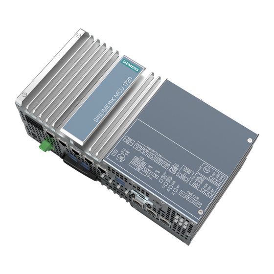
Introduction 2.2 Configuration SINUMERIK MCU 1720 Configuration SINUMERIK MCU 1720 Configuration SINUMERIK MCU 1720 with SINAMICS S120 and S210 Figure 2-2 Example: Simplified schematic of a SINUMERIK MCU configuration MCU commissioning: NC, PLC, Drive Commissioning Manual, 02/2020, A5E47437618B AB... -
Page 22: Procedure For The Initial Commissioning
Introduction 2.3 Procedure for the initial commissioning Procedure for the initial commissioning Checking the system The mechanical and electrical installation of the system must be completed. The following is important when starting commissioning: ● The control system with its components boots error-free. ●... - Page 23 Introduction 2.3 Procedure for the initial commissioning Sequence Reference to Chapter ④ Commission the SINAMICS drive system → Commissioning NC-controlled drives (Page 99) ⑤ Commission the NC: ● Assign the NC machine data for the communication → NC commissioning (Page 145) ●...
- Page 24 Introduction 2.3 Procedure for the initial commissioning MCU commissioning: NC, PLC, Drive Commissioning Manual, 02/2020, A5E47437618B AB...
-
Page 25: Requirements For Commissioning
You can find further information for installing and connecting drive components and their interfaces in: ● SINAMICS S120 Equipment Manual ● SINAMICS S210 Operating Instructions ● SINUMERIK MC Equipment Manual MCU 1720 MCU commissioning: NC, PLC, Drive Commissioning Manual, 02/2020, A5E47437618B AB... -
Page 26: Software And Hardware Preconditions
Requirements for commissioning 3.2 Software and hardware preconditions Software and hardware preconditions Requirements for commissioning To commission the SINUMERIK MC, the following requirements must be met: ● Hardware requirements – SINUMERIK MCU 1720 – SD card – PC (Windows10), with monitor, mouse, and keyboard ●... -
Page 27: Position Of The Interfaces
Requirements for commissioning 3.3 Position of the interfaces Position of the interfaces Interfaces on the MCU The MCU has the following interfaces: X1 P1 Industrial Ethernet Ethernet interfaces (e.g. for system and company network) X2 P1 X3 P1 X3 (optional) COM1 Serial interfaces (optional) COM2... -
Page 28: Power-On And Boot-Up
Initiates a factory reset Note To activate MRES, keep the switch position pressed. Further information Information regarding the meanings of the various LEDs is provided in the SINUMERIK MC Equipment Manual MCU 1720 MCU commissioning: NC, PLC, Drive Commissioning Manual, 02/2020, A5E47437618B AB... - Page 29 Requirements for commissioning 3.4 Power-On and boot-up Reset for commissioning In order to achieve a defined state of the complete system, when commissioning the MCU, an NC general reset and a PLC reset must be performed. Note In the following cases, the PLC must always be restored to its factory settings: ●...
-
Page 30: Resetting The Nc And Plc Separately
Requirements for commissioning 3.4 Power-On and boot-up Note The PLC can only be restored to the delivery condition with the toggle switch position MRES while the control system is running up 3.4.2 Resetting the NC and PLC separately General reset of the NC Carry out the following actions to perform an NC general reset: 1. -
Page 31: Boot Completed
Requirements for commissioning 3.4 Power-On and boot-up Restoring the factory settings puts the PLC into a defined initial state: ● The PLC data have been deleted from the SD card. ● The retentive data are initialized. ● The IP address assigned via TIA Portal has been cleared. 3.4.3 Boot completed Run-up completed without error... -
Page 32: Check The Nc And Ipc Connection Of The Mcu And Configure
Note The application is a system tool and part of TIA Portal. This is how you check or configure the network settings of MCU components using the Siemens communication settings application 1. Under Windows, select "Start > Control panel" > "All control panel elements". - Page 33 Requirements for commissioning 3.5 Check the NC and IPC connection of the MCU and configure 4. Check or configure the following settings: – The DHCP server function is deactivated. – The standard IP address 192.168.214.241 has been entered. 5. Click "Apply". 6.
-
Page 34: Installing Sinumerik Commissioning
Description You must set the PG/PC interface to enable communication between TIA Portal or SINUMERIK Commissioning and MCU. To make the configuration, use the Siemens communication settings application. If you select an interface parameter assignment, then assign this to the access point. This means that you establish the connection between the access point, the interface parameter assignment and the interface itself. - Page 35 Note The application is a system tool and part of TIA Portal. This is how you configure the PG/PC interface using the Siemens communication settings application 1. Under Windows, select "Start > Control Panel" > "All control panel elements" 2. Click "Communication settings".
-
Page 36: Starting And Setting Up Sinumerik Commissioning
Alternatively, you can also configure the connection between SINUMERIK Commissioning and the MCU via file mmc.ini. Copy of the file from directory .../siemens/sinumerik/hmi/cfg and insert the copy below user or oem with the same path. Change the IP addresses and start SINUMERIK Commissioning. -
Page 37: Access Levels
Requirements for commissioning 3.7 Access levels Access levels Access to functions and machine data The access concept controls access to functions and data areas. Access levels 1 to 7 are available, where 1 represents the highest level and 7 the lowest level. Access levels 1 to 3 are locked using a password and 4 to 7 using the appropriate key-operated switch. - Page 38 ● Following a software upgrade, the SINUMERIK Commissioning passwords apply to the NC. ● Once changed, a password can no longer be reset - not even by SIEMENS service. Therefore, make sure that you store the changed password in a safe place.
- Page 39 Requirements for commissioning 3.7 Access levels 3. Press the "Set password" softkey. The current key-operated switch setting is displayed first: 4. Enter the password for the desired access level and confirm this input with "OK" or with the <INPUT> button. A valid password is acknowledged as set and the access level is set.
- Page 40 Requirements for commissioning 3.7 Access levels Change password Procedure: 1. To change the default password from the delivery condition, press the "Change password" softkey. 2. The previous password must first be confirmed. After successful authentication, you are forwarded automatically to the following dialog: 3.
-
Page 41: Licensing
Licensing SINUMERIK License Key Basic information on license keys If a license is required for a product, the purchaser receives a CoL (Certificate of License) with the purchase of the license as proof of the right to use this product together with a corresponding license key as the "technical representative"... - Page 42 Licensing 4.1 SINUMERIK License Key SD card as a spare part If the SD card of a SINUMERIK control is replaced, for example, because of defective hardware, the license key loses its validity and the system is no longer operational. In case of defective hardware of the SD card, contact the "Technical Support".
-
Page 43: Web License Manager
Here, a license database administered by Siemens is accessed via the Internet. Finally, the license information including the license key is transferred to the hardware. -
Page 44: License Database
Note Obtaining access data You can obtain the address data for the customer login from the Siemens Industry Mall under the associated selected region with: "> Register" (top). MCU commissioning: NC, PLC, Drive... -
Page 45: How To Perform The Assignment
Licensing 4.4 How to perform the assignment How to perform the assignment Assigning a license to a piece of hardware 1. Determine the hardware serial number and the product name ("type of hardware") on the user interface via the licensing dialog: Commissioning >... -
Page 46: Important Licensing Terms
Licensing 4.5 Important licensing terms Important licensing terms Certificate of License (CoL) The CoL is the proof of the → license. The product may only be used by the holder of the → license or authorized persons. The CoL includes the following data relevant for the license management: ●... - Page 47 Licensing 4.5 Important licensing terms License key The License Key is the "technical representative" of the sum of all the → licenses that are assigned to one particular piece of → hardware, which is uniquely identified by its → hardware serial number.
- Page 48 Licensing 4.5 Important licensing terms MCU commissioning: NC, PLC, Drive Commissioning Manual, 02/2020, A5E47437618B AB...
-
Page 49: Plc Commissioning
PLC commissioning PLC commissioning: Overview The PLC of a SINUMERIK MCU is always installed in the TIA Portal. You commission the PLC by performing the following work steps (Page 19): 1. Configuring the PLC – Create a project – Insert an MCU –... -
Page 50: Starting The Tia Portal
Starting the TIA Portal Precondition ● TIA Portal V16 has been installed. ● SINUMERIK MC STEP 7 Toolbox V16 has been installed. Procedure 1. Start the TIA Portal by double-clicking the link to the Windows desktop or from the Start menu under "All Programs >... -
Page 51: Configuring The Plc
PLC commissioning 5.3 Configuring the PLC Configuring the PLC 5.3.1 Create a project Introduction You create a new project in the following. Within a project, all of the automation tasks required, for example the hardware configuration and the PLC programming, are performed. Precondition ●... -
Page 52: Configuring The Pc System
PLC commissioning 5.3 Configuring the PLC When creating a SINUMERIK MCU in the TIA Portal, all subcomponents and the PC system are simultaneously created. Ethernet is used for the internal communication between the various components. Precondition ● A project is open in the TIA Portal. ●... - Page 53 PLC commissioning 5.3 Configuring the PLC Install WinCC RT Advanced on the PC system if you wish to use the PC system for using the customized user interfaces. You can configure and customize the operating area. Further information on this topic is provided in the TIA Portal help in Chapter "SINUMERIK user interfaces".
-
Page 54: Configuring Profinet For Sinumerik Mcu
PLC commissioning 5.3 Configuring the PLC 5.3.4 Configuring PROFINET for SINUMERIK MCU Introduction Internal and external communication between the devices involved is established via the PROFINET interfaces. In order that PROFINET participants can be correctly addressed, the configured addresses must be set at the various participants. Procedure Proceed as follows to configure the PROFINET interface of the SINUMERIK MCU: 1. -
Page 55: Configuring Profinet On The Pc System
PLC commissioning 5.3 Configuring the PLC 5.3.5 Configuring PROFINET on the PC system Procedure 1. In the network view, click on the PC system in the basic rack of the SINUMERIK MCU. 2. Switch to the inspector window "Properties > General". You can configure the IP addresses of the various PROFINET interfaces in the respective associated properties: –... -
Page 56: Establish The Communication Connection
PLC commissioning 5.3 Configuring the PLC Procedure To compile the configured hardware configuration, proceed as follows: 1. In the project tree, right-click on the SINUMERIK MCU, and select the "Hardware" command in the "Compile" shortcut menu. 2. To compile the PC system, right-click on "PC-System_1" and, in the "Compile" shortcut menu, select command "Hardware". - Page 57 PLC commissioning 5.3 Configuring the PLC Procedure To establish a communication connection between two devices, proceed as follows: 1. In the "Online" menu, select the "Accessible nodes" command. 2. In the drop-down lists "Type of PG/PC interface" and "PG/PC interface", search for the interface used.
-
Page 58: Load Hardware Configuration Into The Plc
PLC commissioning 5.3 Configuring the PLC 3. If you have connected a new device in the meantime, click the "Refresh" button to refresh the list of accessible nodes. 4. Using "Display", transfer to the project tree the device that has been found in the "Online accesses"... - Page 59 PLC commissioning 5.3 Configuring the PLC Procedure Proceed as follows to load the configured hardware configuration to the MCU: 1. In the project tree, right-click the device name, e.g. "MCU", and select the "Download to device > Hardware configuration" command in the shortcut menu. Note Scope of the data to be downloaded Alternatively, you can select one of the other commands to start downloading additional...
- Page 60 PLC commissioning 5.3 Configuring the PLC – Connection with interface/subnet: Specific interface on the MCU or "Try all interfaces" 3. Click on "Start search" and then select the found PLC from "Compatible nodes in the target subnet". Alternatively, you can specify an IP address directly in the "Compatible nodes in the target subnet"...
-
Page 61: Loading The Wincc Runtime Project Into The Pc System
PLC commissioning 5.3 Configuring the PLC 5.3.9 Loading the WinCC runtime project into the PC system Precondition ● The project has been compiled. ● A communication connection exists between the PG/PC (TIA Portal) and the PC system. ● You have started the WinCC Runtime Loader. MCU commissioning: NC, PLC, Drive Commissioning Manual, 02/2020, A5E47437618B AB... - Page 62 PLC commissioning 5.3 Configuring the PLC Procedure Proceed as follows to load the configured hardware configuration to the PC system: 1. In the project tree, right-click the device name, e.g. "PC system_1", and select the "Hardware configuration" command in the "Download to device" shortcut menu. The "Extended download"...
- Page 63 PLC commissioning 5.3 Configuring the PLC 4. Confirm the download with "Load". The "Download preview" dialog opens. Note Consistency check Before the loading, the consistency of the download is checked. This means that a check is performed as to whether the parameterized hardware of the TIA Portal project matches the hardware that has actually been installed.
-
Page 64: Creating A Plc Program
PLC commissioning 5.4 Creating a PLC program Creating a PLC program 5.4.1 Overview of the PLC program The PLC program of a SINUMERIK MCU is modular and comprises the following parts: ● Organization blocks (OB) The SINUMERIK basic PLC program must be opened and initialized in the respective organization blocks (OB) of the PLC program. - Page 65 PLC commissioning 5.4 Creating a PLC program The following figure and associated description illustrate the structure of the PLC program: Note Information on the basic PLC program blocks required in the project The following description does not list all basic PLC program blocks individually that are required for an executable project.
- Page 66 PLC commissioning 5.4 Creating a PLC program MCU commissioning: NC, PLC, Drive Commissioning Manual, 02/2020, A5E47437618B AB...
-
Page 67: Relevant Organization Blocks
PLC commissioning 5.4 Creating a PLC program The PLC always starts up in the RESTART mode, i.e. the PLC operating system runs through block Startup [OB100] after initialization: ● In the startup [OB100], first call LBP_ConfigBP [FC1], which configures and initializes the basic PLC program. -
Page 68: Inserting Program Code For Calling The Basic Program
PLC commissioning 5.4 Creating a PLC program Instead, add these organization blocks yourself and insert call and initialization of the basic program at the beginning of each OB. Table 5-1 Organization blocks of the basic SINUMERIK PLC program Name Address Description PLC basic program block to be called... - Page 69 PLC commissioning 5.4 Creating a PLC program Procedure To insert the program code for calling and initializing the basic SINUMERIK PLC program, proceed as follows: 1. In the project tree, double-click the relevant organization block, e.g. "MCU_1 > PLC_1 > Program blocks >...
-
Page 70: Inserting The Basic Plc Program Into The Project
1. Switch to the "Libraries" task card. 2. Under "Global libraries", select the PLC basic program that matches the firmware version of the inserted MC, e.g. the library "SINUMERIK MC PLC Basic Program V1.13.0.0". MCU commissioning: NC, PLC, Drive Commissioning Manual, 02/2020, A5E47437618B AB... -
Page 71: Inserting Plc Data Types
PLC commissioning 5.4 Creating a PLC program Result The library is opened. In the subfolders, you will find the components of the basic PLC program structured in the following way: Folder Purpose Content "Copy templates > Motion Control Use this "Copy tem‐ Contains all the blocks required for PLC Basic Program >... - Page 72 Procedure Proceed as follows to copy the PLC data types into your project: 1. Switch to the "Libraries" task card and open the system library "SINUMERIK MC PLC Basic Program V1.13.0.0", for example. 2. Drag the folder "Copy templates > Motion Control PLC Basic Program > Motion Control PLC BP data types"...
-
Page 73: Inserting Plc Basic Program Blocks
PLC commissioning 5.4 Creating a PLC program 5.4.5.3 Inserting PLC basic program blocks Requirement ● A SINUMERIK MCU has been created. ● The data types of the basic PLC program blocks are inserted (Page 71). MCU commissioning: NC, PLC, Drive Commissioning Manual, 02/2020, A5E47437618B AB... - Page 74 To copy program blocks of the basic program from a master copy to the program blocks folder of the project tree, proceed as follows: 1. Switch to the "Libraries" task card and open the system library "SINUMERIK MC PLC Basic Program V1.13.0.0", for example.
-
Page 75: Edit Blocks
PLC commissioning 5.4 Creating a PLC program You can check whether the PLC program has been successfully compiled in the inspector window under "Info > Compile". Result The blocks of the SINUMERIK basic PLC program have been copied to your project. The folder structure of the copied elements is taken over. -
Page 76: Programming Examples (Scl)
PLC commissioning 5.4 Creating a PLC program Name Block address or number LBP_ConfigData LBP_InternalDB8 LBP_NC DB10 LBP_ModeGroup DB11 LBP_HMI DB19 LBP_Chan1 … LBP_Chan4 DB21 … DB24 LBP_Axis1 … LBP_Axis8 DB31 … DB38 LBP_TMLoad DB71 LBP_TMSpindle DB72 LBP_TMTurret DB73 LBP_MFuncDecListConfig DB75 LBP_CtrlEnergy DB1000 LBP_SentronPac... - Page 77 PLC commissioning 5.4 Creating a PLC program HTOut := NULL, HTAdr := 2, HTStop := FALSE, HTNotSend := FALSE, NCCyclTimeout := S5T#200MS, NCRunupTimeout := S5T#50S, ListMDecGrp := 0, MMCToIF := TRUE, HWheelMMC := TRUE, MCP_IF_TCS := FALSE, ExtendChanAxMsg := FALSE, HMIAxisSel := FALSE, MsgUser := 10, IRAuxfuT := FALSE,...
- Page 78 PLC commissioning 5.4 Creating a PLC program ActiveChan => "LBP_ConfigData".ActiveChan, ActiveAxis => "LBP_ConfigData".ActiveAxis, MaxNumUserDataInt => "LBP_ConfigData".MaxNumUserDataInt, MaxNumUserDataHex => "LBP_ConfigData".MaxNumUserDataHex, MaxNumUserDataReal => "LBP_ConfigData".MaxNumUserDataReal, UserDataIntArray => NULL, UserDataHexArray => NULL, UserDataRealArray => NULL, TMMagazines => NULL); //INSERT USER PROGRAM HERE Examples for calling LBP_MainBP [FC2] Call LBP_MainBP [FC2] in Main [OB1], thus starting cyclic processing of the SINUMERIK PLC basic program.
- Page 79 PLC commissioning 5.4 Creating a PLC program Program code to be inserted into the hardware interrupt OB // GP: "LBP_typeNCKProcessIRTFlags"; // NckEvent : Bool; // Axis1InPos: Bool; // Axis2InPos: Bool; // Axis3InPos: Bool; // AuxFunctionInChan1: Bool; // AuxFunctionInChan2: Bool; // TMCommand: Bool; //Call with output parameters "LBP_NCKProcessIRT"(Flags=>#GP);...
- Page 80 PLC commissioning 5.4 Creating a PLC program END_IF; Example 3 - as nested call without transfer of the output parameters In this example "LBP_NCKProcessIRT [FC3]" is called nested over an own FC (e.g. hardware interrupt [OB40] > MyProcessAlarmFC [FC30] > LBP_NCKProcessIRT [FC3]) without transfer of the output flags.
-
Page 81: Handling Of Blocks And Libraries
PLC commissioning 5.4 Creating a PLC program 5.4.6 Handling of blocks and libraries 5.4.6.1 Use and handling of groups In the Program blocks folder in the project tree, you can call the command "Add new group" in the shortcut menu to create groups to organize your program blocks. For example, this function is useful in the following situations: ●... -
Page 82: Copying Blocks Into A Project
PLC commissioning 5.4 Creating a PLC program To maximize the overview window, select the "Program blocks" folder and click the "Maximizes/ minimizes the Overview" icon on the project tree toolbar. 5.4.6.2 Copying blocks into a project Here the procedure how to copy blocks from one project to another is described. Alternatively, the library functionality in the TIA Portal can be used. - Page 83 PLC commissioning 5.4 Creating a PLC program 3. Navigate in the reference project to the "Program blocks" folder and select the blocks that you want to copy. 4. Drag-and-drop the blocks from the reference project to the "Program blocks" folder of your current project.
- Page 84 PLC commissioning 5.4 Creating a PLC program Note Copy additional objects separately (e.g. variables or PLC data types) When you copy the program blocks, objects that belong together, such as variables, PLC data types or technology objects, are not automatically included in the copy. This applies both to copying from reference projects and to copying to another PLC.
-
Page 85: Conflicts When Copying Blocks
PLC commissioning 5.4 Creating a PLC program 5.4.6.3 Conflicts when copying blocks Two different conflict types can occur during copying and pasting of program blocks: ● If several blocks with the same block numbers exist in the "Program blocks" folder, a message is not displayed immediately. -
Page 86: Block Address Range For Plc User Program
PLC user program. Table 5-3 Assignment overview of the DB numbers DB number Availability Occupied by Reserved Siemens 2 … 3 Occupied Siemens (basic PLC program) 4 … 7 Reserved Siemens Occupied Siemens (basic PLC program) Reserved Siemens 10 … 11 Occupied... - Page 87 5.4 Creating a PLC program DB number Availability Occupied by Reserved Siemens 21 … 24 Occupied¹ Siemens (basic PLC program: inter‐ face for NC channels) 31 … 38 Occupied¹ Siemens (basic PLC program: inter‐ face for axes/spindles) 62 … 70 Freely available (user program)
- Page 88 PLC commissioning 5.4 Creating a PLC program FB number Availability Occupied by 25000 … 32766 Reserved Siemens (basic PLC program) 32767 … 65535 Reserved² Standard number range for gener‐ ated F-system blocks Table 5-5 Assignment overview of the FC numbers...
-
Page 89: Nck Hardware Interrupts
PLC commissioning 5.4 Creating a PLC program 5.4.7 NCK hardware interrupts 5.4.7.1 General information on hardware interrupt OBs If a hardware interrupt is triggered by a module during runtime, the hardware interrupt OB defined in the associated event is triggered or entered in the queue depending on its priority. ●... -
Page 90: Identification Of An Nck Event In The Plc Program
PLC commissioning 5.4 Creating a PLC program Signal type Handover to Acknowledg‐ Remark user ment to NCK Auxiliary function to be exe‐ Hardware inter‐ Immediately in An auxiliary function can be defined as an auxiliary cuted event-driven rupt OB the hardware in‐ function that is executed event-driven by setting the terrupt OB corresponding parameter of the LBP_ConfigBP [FC1]:... -
Page 91: Defining Nck Hardware Interrupt Event
PLC commissioning 5.4 Creating a PLC program Whether or not an event was triggered by the NCK can be queried as follows: ● LADDR in the start information of the hardware interrupt OB LADDR contains the hardware identifier of the module that has triggered the hardware interrupt. - Page 92 PLC commissioning 5.4 Creating a PLC program Procedure Proceed as follows to configure process alarms in the properties of the NCK: 1. Click on the "NCK" module in the network view or device view. 2. In the "Properties" inspector window, select the "Events" entry. The hardware interrupt settings are displayed.
-
Page 93: Use Of The Associated System Constant
PLC commissioning 5.4 Creating a PLC program Note Hardware interrupts: Response for NCK events You must issue an attach command before an event occurs from the part program (by executing a command to output a fast help function). If you do not issue an attach command, then the NCU is brought into state "Wait for HiFu acknowledgment". -
Page 94: Assigning Hardware Interrupt Ob During Runtime
PLC commissioning 5.4 Creating a PLC program The system constant with the data type "Hw_Interface" contains the HW identifier of the DP- Integrated interface on the NCK (initiating module for NCK events). 5.4.7.6 Assigning hardware interrupt OB during runtime In special applications (e.g. modular machine) it probably makes sense not to select the hardware interrupt OB in the project in the NCK events, but during the runtime in the user program using an attach command instead. -
Page 95: Loading The Plc Program To The Plc
PLC commissioning 5.4 Creating a PLC program 5.4.8 Loading the PLC program to the PLC Introduction For loading the configured PLC project, the following preconditions must be fulfilled: Precondition ● A network connection exists between the PG/PC and the PLC. ●... - Page 96 PLC commissioning 5.4 Creating a PLC program Result The PLC is stopped and the PLC program is loaded into the PLC. The "Results of the loading action" dialog opens and displays the status of the loading action. The dialog restarts the PLC after completion provided the "Start"...
-
Page 97: First Commissioning Of The Plc Completed
PLC commissioning 5.5 First commissioning of the PLC completed First commissioning of the PLC completed First commissioning of the PLC completed Note A reset (warm restart) of the NC is required for PLC-NC synchronization. The PLC and NC are in the following state after a reset (warm restart): ●... - Page 98 PLC commissioning 5.5 First commissioning of the PLC completed MCU commissioning: NC, PLC, Drive Commissioning Manual, 02/2020, A5E47437618B AB...
-
Page 99: Commissioning Nc-Controlled Drives
A SINUMERIK MC is designed for use with the following drive systems: ● SINAMICS S120 (CU320-2) ● SINAMICS S210 You create the drive system suitable for your application and network it with a SINUMERIK MC. Possible commissioning methods ● Basic commissioning using "SINAMICS Startdrive" in the TIA Portal, followed by fine parameterization in SINUMERIK Commissioning Precondition: "SINAMICS Startdrive"... -
Page 100: Commissioning Drives With "Startdrive
Commissioning NC-controlled drives 6.2 Commissioning drives with "Startdrive" Commissioning drives with "Startdrive" 6.2.1 Overview You integrate drives of the SINAMICS family contained in the "SINAMICS Startdrive" option package in the TIA Portal using the "Startdrive" engineering tool. You commission the SINAMICS S120 (CU320-2) and SINAMICS S210 drive systems via Startdrive by performing the following worksteps: ●... - Page 101 Commissioning NC-controlled drives 6.2 Commissioning drives with "Startdrive" All assignable components are listed in the table and are assigned as follows: ● Components are assigned to drive objects. ● Drive objects are assigned to drive units. Note Overwriting existing data in the device configuration Existing components and their configuration are overwritten by the automatically detected device configuration.
- Page 102 Commissioning NC-controlled drives 6.2 Commissioning drives with "Startdrive" Starting the device configuration detection 1. You can start device configuration detection in one of the following ways: – Project tree: In the shortcut menu of a drive unit or of a CU in the project tree, select the "Device configuration detection"...
- Page 103 Commissioning NC-controlled drives 6.2 Commissioning drives with "Startdrive" Components that cannot be assigned to any main component are displayed in the drop- down entry "Non-assignable components." 2. To cause an LED of a particular module in your actual topology to flash, select the "LED Flashing"...
- Page 104 Commissioning NC-controlled drives 6.2 Commissioning drives with "Startdrive" Assigning components If all components found in the actual topology have been assigned, no further adaptations must be made in the "Device configuration detection" dialog. The "Create" button can then be selected. If the "Create"...
- Page 105 Commissioning NC-controlled drives 6.2 Commissioning drives with "Startdrive" Cancelling a parallel connection You can cancel an existing parallel connection as follows: 1. Drag components to the higher-level drive unit using drag-and-drop. - Or - 2. Select a component connected in parallel and select the "Disconnect parallel connection" shortcut menu.
-
Page 106: Inserting The Drive Offline
Commissioning NC-controlled drives 6.2 Commissioning drives with "Startdrive" 6.2.3 Inserting the drive offline Introduction You can also create drive units manually in the TIA Portal. You configure your SINAMICS drive offline in the "Device view". You insert the individual components of the SINAMICS drive and connect them. Preconditions ●... - Page 107 Commissioning NC-controlled drives 6.2 Commissioning drives with "Startdrive" Procedure Proceed as follows to insert a SINAMICS S drive: 1. Double-click "Add new device" in the project navigation. The "Add new device" dialog box opens. 2. Click the "Drives" button to limit the list of devices to just drives. All of the available SINAMICS control modules are now displayed in the drop-down list.
- Page 108 Commissioning NC-controlled drives 6.2 Commissioning drives with "Startdrive" 5. Click "OK" to confirm your settings. As soon as the "Open device view" option is activated, the SINAMICS drive is automatically created and displayed in the device view. The drive appears below "drive_unit_1" in the project navigator. 6.
- Page 109 Commissioning NC-controlled drives 6.2 Commissioning drives with "Startdrive" The components used by the SINAMICS drive are listed in the "Device overview". Result As soon as the drive system has been created, it appears in the project navigator under "drive_unit_1" together with the following entries: ●...
-
Page 110: Networking The Drive With The Control System
Commissioning NC-controlled drives 6.2 Commissioning drives with "Startdrive" ● Parameter: – Function view: Parameter assignment on the graphical interface. The individual screen forms are based on the function diagrams and include the parameters required. – Parameter view: Clearly organized representation of the parameters available for the device. -
Page 111: Preparing Communication Via Profinet Io
Commissioning NC-controlled drives 6.2 Commissioning drives with "Startdrive" Procedure Proceed as follows to establish the connection between the SINUMERIK MC and the SINAMICS drive: 1. Switch to the network view. 2. In the drive view, click "Not assigned" and under "Select IO controller" select "MCU_1.PLC_1.PROFINET_Interface_150". - Page 112 Commissioning NC-controlled drives 6.2 Commissioning drives with "Startdrive" To configure the sync domain, proceed as follows: 1. Select the PROFINET IO system in the network view. 2. In the Inspector window, click the "General" tab and select "Domain management > Sync domain >...
-
Page 113: Configuring Topology And Ports
Commissioning NC-controlled drives 6.2 Commissioning drives with "Startdrive" Explanation of the parameters Parameter Description Sync domain Name of the sync domain. This name is converted automatically if it does not conform with the DNS conventions. IO devices Here, you can see a list of the IO devices of the sync domain. You can select the following parameters for the nodes: ●... - Page 114 Commissioning NC-controlled drives 6.2 Commissioning drives with "Startdrive" Port interconnection via the properties After the selection of a device or an interface, the entries for the ports are displayed in the Inspector window in the "General" tab at "PROFINET PN / IO interface > Advanced options" or "Advanced options".
-
Page 115: Set Up The Sync Master And Sync Slave
Commissioning NC-controlled drives 6.2 Commissioning drives with "Startdrive" 6.2.5.3 Set up the sync master and sync slave. Preconditions You have performed the following configuration steps: ● IO controller and IO device configured with RT ● Port interconnections are configured Configuring the sync master To configure a sync master, proceed as follows: 1. - Page 116 Commissioning NC-controlled drives 6.2 Commissioning drives with "Startdrive" Configuring the IO device as a sync slave To configure a device within a PROFINET IO system as a sync slave, proceed as follows: 1. Select the PROFINET interface for the sync slave in the network view, e.g. the interface of the drive system.
-
Page 117: Configure Isochronous Io Device
Commissioning NC-controlled drives 6.2 Commissioning drives with "Startdrive" 6.2.5.4 Configure isochronous IO device Configuring isochronous mode for IO devices The drive and controller together form a sync domain. You must parameterize the IRT operating mode (for isochronous drives) and the PROFINET settings for motion control applications of the PROFINET IO system. - Page 118 Commissioning NC-controlled drives 6.2 Commissioning drives with "Startdrive" Parameterizing isochronous mode Isochronous mode can be activated and deactivated for each IO device or module in the IO device. You will find a more detailed description of the possible settings for isochronous mode in the following table.
-
Page 119: Configuring Telegrams
Commissioning NC-controlled drives 6.2 Commissioning drives with "Startdrive" Parameter Description Intervals Indicates in which interval the value will be read in. The value should not be changed. Time To (setpoint) Specifies at what time To, the setpoint will be read out after the end of the cycle. Interval Indicates in which interval the value will be read in. -
Page 120: Displaying Telegram Configuration
Telegram overview The following table shows the telegrams for PROFIdrive communications: Drive system Designation Purpose S120 SIEMENS tele‐ Manufacturer-specific telegram. gram 136 Permits the use of the following data: ● Dynamic Servo Control (DSC) ● Torque feedforward control ● 2 position encoders (encoder 1 and encoder 2) ●... -
Page 121: Settings For Sinamics S120
Commissioning NC-controlled drives 6.2 Commissioning drives with "Startdrive" Calling telegram configuration via project navigator 1. In the network view, select the IO device (S210 drive) and then click the PROFINET interface. 2. In the Inspector window, select "Properties > Telegram configuration". The telegram configuration settings are displayed. -
Page 122: Settings For Sinamics S210
Commissioning NC-controlled drives 6.2 Commissioning drives with "Startdrive" In the telegram configuration area, you can create telegrams and view their properties. 6.2.6.4 Settings for SINAMICS S210 Telegram configuration for S210 drives The dialog box for the telegram configuration is structured as follows: In the telegram configuration area, you can create telegrams and view their properties. -
Page 123: Parameterizing Sending (Actual Value/Safety Actual Value)
Can only be changed on "free telegrams". Extension Most standard telegrams or Siemens telegrams can be changed. Safety Integrated telegrams and free telegrams cannot be extended. Enter the telegram extension here for the transfer of the actual value. If you have entered an extension at "Telegram configuration", it is also displayed... - Page 124 Commissioning NC-controlled drives 6.2 Commissioning drives with "Startdrive" Parameter Drive Controller Consistency The use of various consistency areas is useful to optimize the performance of an S7-CPU. Consistency areas that are longer than two words must be edited with system functions. You can use the effective Load/Transfer com‐ mands for consistency areas up to two words.
-
Page 125: Parameterizing Receiving (Setpoint/Safety Setpoint)
Can only be changed on "free telegrams". Extension Most standard telegrams or Siemens telegrams can be changed. Safety Integrated telegrams and free telegrams cannot be extended. Enter the telegram extension here for the transfer of the setpoint. If you have entered an extension at "Telegram configuration", it is also displayed here. -
Page 126: Structure Of The Telegrams, Control And Status Words
Commissioning NC-controlled drives 6.2 Commissioning drives with "Startdrive" Parameter Drive Controller Consistency The use of various consistency areas is useful to optimize the performance of an S7-CPU. Consistency areas that are longer than two words must be edited with system functions. You can use the effective Load/Transfer com‐ mands for consistency areas up to two words. -
Page 127: Editing Telegrams
6.2.6.8 Editing telegrams Overview You can edit telegrams in the following way: ● Extending standard or Siemens telegrams ● Adding telegrams Requirement ● You have created a SINUMERIK MCU and a SINAMICS drive (S210 or S120) and connected them via a PROFINET fieldbus. - Page 128 However, the length of these telegrams can be changed. ● Safety Integrated telegrams: – PROFIsafe telegrams 30, 31 – Siemens- telegrams 901, 902, 903 ● Currently on S210 drives, a selected telegram cannot be extended, which is why the field "Extension" is grayed out.
-
Page 129: Commissioning Drives Via Device Master Files
● A SINUMERIK MCU has been inserted. Procedure 1. Switch to the "Network view". 2. In the hardware catalog under "Further field devices > PROFINET IO > Drivers > SIEMENS AG > SINAMICS > Head module", select a drive, e.g "SINAMICS S120/S150 CU320-2 PN Vx.x". - Page 130 Commissioning NC-controlled drives 6.3 Commissioning drives via device master files 4. To establish a connection to the PN IO interface of the controller, in the drive view, click "Not assigned" and under "IO controller" select "MCU_1.PLC_1.PROFINET_Interface_150". The PROFINET IO system is created and the drive is assigned to the control. 5.
-
Page 131: Configuring Network Settings For The Drive
Commissioning NC-controlled drives 6.3 Commissioning drives via device master files 6.3.3 Configuring network settings for the drive Preconditions ● The TIA Portal has been started. ● A SINUMERIK MCU has been inserted. ● The drive and control are interconnected. MCU commissioning: NC, PLC, Drive Commissioning Manual, 02/2020, A5E47437618B AB... - Page 132 Commissioning NC-controlled drives 6.3 Commissioning drives via device master files Procedure 1. Under "Project navigation > Ungrouped devices", double-click the drive you created. The device configuration for the drive is displayed in the Inspector window. 2. In the Inspector window under "Properties > General > PROFINET interface [X150] > Ethernet addresses", in the "IP Protocol"...
-
Page 133: Configuring Telegrams For Communication
Commissioning NC-controlled drives 6.3 Commissioning drives via device master files 6.3.4 Configuring telegrams for communication Introduction You need a telegram for the communication between a control and a drive. Any axis that you operate on the control must be created via the "DO SERVO" module from the hardware catalog. - Page 134 2. In the hardware catalog, select the following drive objects and drag them onto the device overview: – Under "Module", module "DO SERVO" – Under "Submodules", telegram "Siemens telegram 136, PZD-15/19" – Under "Module", module "DO control unit" – Under "Submodules", telegram "Siemens telegram 391, PZD-3/7"...
- Page 135 Commissioning NC-controlled drives 6.3 Commissioning drives via device master files 3. In the device overview, select telegram "Siemens telegram 136, PZD-15/19". The telegram configuration is displayed in the Inspector window. 4. In the Inspector window under "Properties > General > I/O addresses", make the following settings for input addresses and output addresses: –...
-
Page 136: Completing The Configuration
Commissioning NC-controlled drives 6.3 Commissioning drives via device master files 6.3.5 Completing the configuration Introduction To complete the configuration, make the following settings: ● Check and set the send cycle clock on the PLC to allow synchronization of PROFINET IO devices and improve the precision of the cyclic data exchange via PROFINET IO. - Page 137 Commissioning NC-controlled drives 6.3 Commissioning drives via device master files Setting the send cycle clock on the PLC Proceed as follows to set the send cycle clock on the PLC: 1. In the network view, click the PLC in the basic rack of the SINUMERIK MCU. 2.
- Page 138 Commissioning NC-controlled drives 6.3 Commissioning drives via device master files You can edit the Ti/To values in "Manual" mode. Checking settings for the sync domain A sync domain is needed to synchronize PROFINET IO devices. To check the assignment of the device to the sync master and sync slave and other sync domain settings, proceed as follows: 1.
- Page 139 Commissioning NC-controlled drives 6.3 Commissioning drives via device master files 3. Under "General", click "PROFINET Subnet > Domain management > Sync domains > Sync- Domain_1". 4. Check the settings, in particular, the assignment of the devices in the "IO devices" section, and complete where necessary.
- Page 140 Commissioning NC-controlled drives 6.3 Commissioning drives via device master files 3. Check the settings for the port interconnection. 4. If necessary, edit the other parameters of the port. MCU commissioning: NC, PLC, Drive Commissioning Manual, 02/2020, A5E47437618B AB...
-
Page 141: Setting The Basic Parameters In Sinumerik Commissioning
Commissioning NC-controlled drives 6.4 Setting the basic parameters in SINUMERIK Commissioning Setting the basic parameters in SINUMERIK Commissioning 6.4.1 Overview of NC and drive communication After basic commissioning in "SINAMICS Startdrive" in the TIA Portal, you must make the following settings in SINUMERIK Commissioning to allow communication between the drive and the NC: ●... - Page 142 Commissioning NC-controlled drives 6.4 Setting the basic parameters in SINUMERIK Commissioning Assignment of S210/S120 general machine data The following table lists the general machine data for the S210 and S120 drive systems that you must configure accordingly in SINUMERIK Commissioning: Number Designation Value...
- Page 143 Commissioning NC-controlled drives 6.4 Setting the basic parameters in SINUMERIK Commissioning Number Designation Value Meaning MD32250 $MA_RATED_OUTVAL 100 % Rated output voltage; The rated output voltage must be adapted to the rated speed of the analog drive: MD32260 $MA_RATED_VELO According to the real rated motor Rated motor speed speed MD30220[0..1] $MA_ENC_MODULE_NR...
- Page 144 Commissioning NC-controlled drives 6.4 Setting the basic parameters in SINUMERIK Commissioning MCU commissioning: NC, PLC, Drive Commissioning Manual, 02/2020, A5E47437618B AB...
-
Page 145: Nc Commissioning
NC commissioning Machine and setting data Setting machine data Adaptation of the control at the machine is performed using the machine and setting data. ● The machine data (MD) is divided into the following areas: – General machine data – Channel-specific machine data –... - Page 146 Changes to the setting data always take effect immediately. Further information A description of the machine data and setting data is provided in the SINUMERIK MC Machine Data List Manual MCU commissioning: NC, PLC, Drive Commissioning Manual, 02/2020, A5E47437618B AB...
-
Page 147: Procedure When Commissioning The Nc
NC commissioning 7.2 Procedure when commissioning the NC Procedure when commissioning the NC NC commissioning We recommend the following sequence when commissioning the NC: Sequence Reference ① Parameter sets of axis/spindle Function Manual Axes and Spindles: ● Velocities, setpoint/actual value systems, closed-loop control ●... - Page 148 In order to set all the technology-relevant data for a turning machine or milling machine on the control, the following user views are available to facilitate the commissioning: ● Setup_Milling ● Setup_Turning The files are stored on the SD card under: /user/sinumerik/hmi/template/user_views/param Product announcement (https://support.industry.siemens.com/cs/document/ 80582059) MCU commissioning: NC, PLC, Drive Commissioning Manual, 02/2020, A5E47437618B AB...
-
Page 149: Configuring Machine Axes
NC commissioning 7.3 Configuring machine axes Configuring machine axes 7.3.1 Axis assignment Introduction Generally, a distinction is made between four types of axes: ● Machine axes Machine axes are the motion units existing on a machine, which can also be designated as linear or rotary axes, depending on their usable movement. - Page 150 NC commissioning 7.3 Configuring machine axes Axis assignment The assignment of geometry axes to channel axes and channel axes to machine axes, as well as the definition of the names of the different axis types is realized via machine data. The following diagram illustrates this relationship: Figure 7-1 Axis assignment...
- Page 151 NC commissioning 7.3 Configuring machine axes Channel axis gaps Normally, using MD20070, a channel axis is assigned to one machine axis. Not every channel axis must be assigned to a machine axis. Each channel axis with MD20070 [n] = 0 is not assigned any machine axis and represents a channel axis gap.
-
Page 152: Axis Names
NC commissioning 7.3 Configuring machine axes Figure 7-2 Axis configuration with channel axis gap 7.3.2 Axis names Machine axes Each machine axis, channel axis and geometry axis is assigned an individual name that clearly identifies the axis. Machine axis names must be unambiguous for the entire NC. The name of the machine axes are defined via the following machine date: MD10000 $MN_AXCONF_MACHAX_NAME_TAB [n] (machine axis name) The specified names and the associated index are used in the following cases:... -
Page 153: Drive Assignment
NC commissioning 7.3 Configuring machine axes MD20060 $MC_AXCONF_GEOAX_NAME_TAB [n] (geometry axis in the channel) The names for channel and geometry axes are used in the part program for programming general traversing movements and to describe the workpiece contour. ● Path axes ●... - Page 154 NC commissioning 7.3 Configuring machine axes Assignment: 1. Using this machine data, the NC is informed about the I/O addresses of the SERVO drive objects defined in the PLC project: MD13050 $MN_DRIVE_LOGIC_ADDRESS[n] 2. Using the following machine data, the setpoint and actual values of the machine axes are assigned to the relevant drive objects: –...
-
Page 155: Configuring Drive Units With Sinumerik Commissioning
NC commissioning 7.4 Configuring drive units with SINUMERIK Commissioning Configuring drive units with SINUMERIK Commissioning PROFINET connection The following general machine data are also set by default for the PROFINET connection of the axes to the drive: ● MD13050 $MN_DRIVE_LOGIC_ADDRESS (axis address) ●... - Page 156 Communication with the drive To ensure communication with the drive, the I/O addresses and telegram types set here must match the settings in the hardware configuration in the SINUMERIK MC STEP 7 Toolbox. MCU commissioning: NC, PLC, Drive Commissioning Manual, 02/2020, A5E47437618B AB...
-
Page 157: Configuring The Measuring Probe
7.5.1 Measuring probe general Measuring for S120 and S210 SINAMICS S120 and S210 drives are connected to SINUMERIK MC via PROFINET IO. This means that for both drives only distributed measuring is possible: ● Central measuring for SINAMICS S120 CU320-2: For the S120, measuring probes 1 and 2 (X122 oder X132) are connected via terminals to the CU. - Page 158 For SINAMICS S210, the measuring probes are directly connected to the digital inputs. You have already created a SINUMERIK MC and a SINAMICS S210 in the TIA Portal and configured the communication. The configuration is performed using Startdrive (TIA Portal) or directly via the web server at the SINAMICS S210 1.
-
Page 159: Central Measuring Probe With S120
NC commissioning 7.5 Configuring the measuring probe 7.5.3 Central measuring probe with S120 Connecting signals at the drive For SINAMICS S120, measuring probes are connected at terminals X122 or X132 of the Control Unit Measuring probe connected to SINAMICS S120 For SINAMICS 120, measuring probes are connected at the bidirectional inputs/outputs of X122 or X132. - Page 160 NC commissioning 7.5 Configuring the measuring probe MCU commissioning: NC, PLC, Drive Commissioning Manual, 02/2020, A5E47437618B AB...
-
Page 161: Creating And Importing Archives Using Sinumerik Commissioning
On the one hand, commissioning archives are used to save a specific control status and to restore it (Backup), on the other hand, they allow you to configure a machine series using the same data (Setup). In SINUMERIK MC, these two archive types are supported with the DSF format (Data Storage Folder). - Page 162 Creating and importing archives using SINUMERIK Commissioning 8.1 Overview for archiving and data backup Note The DSF archive is compressed as a zip file, which contains a file tree with user data and attributes. Archive options There are various ways of creating and reloading archives via the SINUMERIK ONE Commissioning Tool user interface.
- Page 163 Creating and importing archives using SINUMERIK Commissioning 8.1 Overview for archiving and data backup Note Logs for the last import can be found in the following directory in the *.log format: HMI data > Logs > Commissioning Data areas The following data areas are backed up in a commissioning archive: Components Data Backup...
-
Page 164: Importing The Archive Into The Sinumerik Mc
8.2 Importing the archive into the SINUMERIK MC Importing the archive into the SINUMERIK MC A DSF archive can be imported in the usual way into the SINUMERIK MC environment via the user interface of SINUMERIK Commissioning. This allows you to commission NC and PLC components. - Page 165 Creating and importing archives using SINUMERIK Commissioning 8.2 Importing the archive into the SINUMERIK MC 3. Select the archive and confirm with "OK". You obtain an overview with path details, version information, name of the archive, etc., as well as a list of the archived components.
-
Page 166: Creating A Dsf Archive On Sinumerik Mc
● Data backup at a defined storage location Note We recommend that a backup archive is created regularly for specified work states of the SINUMERIK MC environment so that a required state can be reproduced whenever necessary. Note Restriction An original archive is represented as backup. - Page 167 Creating and importing archives using SINUMERIK Commissioning 8.3 Creating a DSF archive on SINUMERIK MC "Create archive" view Parameter Remark for configuration Header The header shows the selected archive type. NCU components Selected components to be written to the archive: ●...
- Page 168 Creating and importing archives using SINUMERIK Commissioning 8.3 Creating a DSF archive on SINUMERIK MC Procedure 1. In SINUMERIK Commissioning, switch over to the "Commissioning" operating area via "MENU SELECT > Commissioning > Commissioning archives". 2. Select one of the options for creating an archive and confirm with "OK".
-
Page 169: Installation / Upgrading
Installation / upgrading With the help of an MCU service system 9.1.1 Introduction, upgrading Upgrade options You have the option of initiating an upgrade of the CNC software with a USB flash drive: Note An upgrade is possible as of CNC software 1.12. An upgrade from other software versions is not permitted. -
Page 170: Upgrading The Cnc Software Using Vnc Viewer On Pc/Pg
Installation / upgrading 9.1 With the help of an MCU service system 9.1.2 Upgrading the CNC software using VNC Viewer on PC/PG Flow diagram Figure 9-1 Upgrading the CNC software using VNC Viewer on PC/PG MCU commissioning: NC, PLC, Drive Commissioning Manual, 02/2020, A5E47437618B AB... -
Page 171: Creating A Service System
Installation / upgrading 9.2 Creating a service system Creating a service system 9.2.1 This is how you create a service system for the MCU Purpose In case service is needed, create a portable "Emergency Boot System" (EBS) on a USB memory. -
Page 172: This Is How You Operate The Service System
Installation / upgrading 9.2 Creating a service system 6. In the menu bar of the program, click "Options" → "Write image to CF card...". Dialog box "Write image to CF card..." opens. 7. In the dialog box, select an image file (.img) and drive letter (e.g. H:\) for the memory medium. - Page 173 Installation / upgrading 9.2 Creating a service system Note Operation with touch panels The service system supports touch operation. The input fields are touch operated and the integrated keyboard automatically appears. For example: SINUMERIK OP 019 black, SIMATIC HMI Industrial Thin Client MCU commissioning: NC, PLC, Drive Commissioning Manual, 02/2020, A5E47437618B AB...
- Page 174 Installation / upgrading 9.2 Creating a service system MCU commissioning: NC, PLC, Drive Commissioning Manual, 02/2020, A5E47437618B AB...
-
Page 175: Installing And Setting Up Pcu Base For Ipc
Overview Software PCU Base for IPC is the basis for operating SINUMERIK software on your SIEMENS PC system: SINUMERIK MC control system Software PCU Base for IPC is compatible for the SINUMERIK MCU 1720 CNC with the following article number: ●... -
Page 176: Supplied Software
SIMATIC IPC: Note Do not switch off SIEMENS PC systems with Windows on the hardware! Loss of data may result on Windows-based systems if the system is not shut down properly before it is disconnected from the power source. For technical reasons, data is still being written to the SSD/SD shortly after shutdown. -
Page 177: Hardware Configuration Of Simatic Ipc
Installing and setting up PCU Base for IPC 10.1 Delivery state Note Acknowledgements ● This product includes cryptographic software written by Eric Young (eay@cryptsoft.com) ● This product includes software developed by the OpenSSL Project for use in the OpenSSL Toolkit. (http://www.openssl.org/) 10.1.2 Hardware configuration of SIMATIC IPC 10.1.2.1... -
Page 178: Partitioning Of The Ssd
Note Do not modify files in the template directory siemens! The siemens directory contains only files with the factory settings that can be copied and used as templates. Your Never overwrite these files. - Page 179 The settings in a configuration file in a directory with higher priority always replace those from one of lower priority. Template directory siemens has the lowest priority. To define your own settings, therefore, copy a setting from the relevant template file into a directory with higher priority, e.g.
-
Page 180: First Commissioning Of Simatic Ipcs
Example workflow Step Description Set up and commissioning Information on setting up and installing your SIEMENS PC system can be found in the corresponding of the PC system (according hardware documentation: to the operating instructions) Install PCU Base for IPC If necessary, adapt the installation settings (Page 180) and install PCU Base for IPC (Page 181). -
Page 181: Installing Pcu Base For Ipc
Installing and setting up PCU Base for IPC 10.2 First commissioning of SIMATIC IPCs Before you adapt the settings in this file, you should copy the original file. Section Setting Description [IPC] FirewallSettings= ● 1 (default setting) The Windows firewall settings are adapted appropriately for the com‐ pany network by the PCU Base for IPC, as described in this documen‐... - Page 182 PCU Base for IPC has been installed. During the installation, the previously existing settings on the SIEMENS PC system, e.g. user accounts, keyboard layout, date and time settings, were imported. Set up additional user accounts (Page 183) if necessary and set the keyboard layout to English (Page 186).
-
Page 183: Configuration Of The System
Installing and setting up PCU Base for IPC 10.3 Configuration of the system 10.3 Configuration of the system 10.3.1 Overview Once you have completed the first commissioning, you can adapt the configuration of the system: ● For security reasons, set up user accounts (Page 183) with limited rights. ●... -
Page 184: Changing The Name Of The Pc System
Installing and setting up PCU Base for IPC 10.3 Configuration of the system 10.3.3 Changing the name of the PC system After installing PCU Base for IPC, a unique computer name is set. You can view and change it in the Control Panel of the Service Desktop. You can find the computer name in the Control Panel under Category "System", Section "Computer name, domain and workgroup settings". -
Page 185: Configuring Network Access On The Usb Data Storage Medium
To configure the automatic network release of USB data storage media of the PC system, proceed as follows: 1. Open the basesys.ini configuration file in the C:\ProgramData\Siemens \MotionControl\user\System\etc\ directory. 2. Remove the semicolon in front of the EnableUSBShares line and set the required value. -
Page 186: Configuring The Keyboard Layout
The setting of the keyboard layout as well as the display of the active keyboard layout is shown in the Windows task bar. 10.3.8 Setting up an external screen You can connect an external screen to the Siemens PC system. The procedure follows the usual procedure under Windows 10. Preconditions ● The PC system is switched off. -
Page 187: Set The Resolution In The Tcu.ini
The system behavior during run-up for the screen resolution is set in the tcu.ini file in Section [VNCServer]. You will find a template of the tcu.ini under C:\ProgramData\Siemens\Motion Control\siemens\System\etc\ Do not overwrite this template, but rather create your own tcu.ini inside one of the user directories. - Page 188 Installing and setting up PCU Base for IPC 10.3 Configuration of the system The meaning of the settings are as follows: Table 10-4 Settings in the configuration file tcu.ini Setting Meaning SYSTEM The resolution is not specially set during run-up. i.e. the resolution last used in the system is active, e.g.
-
Page 189: Setting The Color Depth In The Tcu.ini File
Setting the color depth in the tcu.ini file The color depth of the SIEMENS PC system is set to 16 bit as default setting via the tcu.ini configuration file, and is reset to this value each time the system runs up. -
Page 190: Configuring The Sitop Ups Module For Use With Pcu Base For Ipc
10.3.12.1 Overview of SITOP UPS SITOP UPS modules can continue operation of the SIEMENS PC system temporarily if a power failure occurs and/or shut down the system correctly. For example, a SITOP UPS module also protects against data loss when the SIEMENS PC system hardware is shut down, because for technical reasons with Windows-based systems, data is still written to the SSD after shutdown. -
Page 191: Sitop Modules For Ipc
Installing and setting up PCU Base for IPC 10.3 Configuration of the system ● Catalog KT 10.1 SITOP Power Supply ● SIEMENS Industry Mall > 24 V DC Uninterruptible Power Supplies (https:// eb.automation.siemens.com/mall/en/US/Catalog/Products/7010117) 10.3.12.2 SITOP modules for IPC Suitable SITOP UPS modules SITOP UPS modules can continue operation of a PC system temporarily if a power failure occurs and/or shut down the system correctly. - Page 192 Installing and setting up PCU Base for IPC 10.3 Configuration of the system Precondition ● The SITOP UPS hardware is connected via the USB interface. ● The SITOP software of version 3.x.2.16 or later is installed in directory C:\Program Files (x86)\SITOP\ ●...
- Page 193 Installing and setting up PCU Base for IPC 10.3 Configuration of the system Procedure Proceed as follows to configure the SITOP software for use with PCU Base for IPC: 1. Call the settings of the SITOP software, for example, by right-clicking the SITOP UPS icon in the Windows information area and then selecting "Configuration".
- Page 194 Display of the monitoring window can cause malfunctioning of the HMI software. – Click directly in the text field at "Start application after" and specify the path of the USVShutdown.bat: C:\Program Files (x86)\Siemens\MotionControl\siemens\sinumerik \hmi\base\USVShutdown.bat Note Do not use the "Browse" button The dialog can crash if you use the "Browse"...
- Page 195 Installing and setting up PCU Base for IPC 10.3 Configuration of the system If the HMI software of your OEM installation is not shut down within 180 seconds, you can parameterize this wait time manually. Note Information about the test environment for machine OEMs The function "SITOP UPS"...
- Page 196 2. In the "SITOP DC UPS Configuration" dialog box, enter the wait time in seconds as a command line parameter in the "Buffering" tab: – Syntax: <path>\USVShutdown.bat -<time in seconds> – Example: C:\Program Files (x86)\Siemens\MotionControl\siemens \sinumerik\hmi\base\USVShutdown.bat -180 Figure 10-1 SITOP Monitor Floating operation 3.
-
Page 197: Hardware Configuration Of The Sitop Ups Module
To do this, enter the wait time in seconds as command line parameter: Syntax: <path>\USVShutdown.bat -<time in seconds> Example: C:\Program Files (x86)\Siemens\MotionControl\siemens\sinumerik\hmi\base \USVShutdown.bat -180 4. Confirm the settings with "Configuration changed, restart application now". - Page 198 Installing and setting up PCU Base for IPC 10.3 Configuration of the system On - Off End-of-charge voltage +0.5V + 26.3V fixed +0.2V +0.2V +0.1V 0.35A / 0.7A Charging current On - Off Set time/max. time +320 s +160s Buffer time +80s +40s +20s...
-
Page 199: Configuration Of The Service Center
Installing and setting up PCU Base for IPC 10.3 Configuration of the system On - Off ∘ ∘ End-of-charge voltage +0.5V + 26.3V fixed +0.2V +0.2V +0.1V 0.35A / 0.7A Charging current On - Off Set time/max. time +320 s ∘... -
Page 200: Configuration Of The Network Adapter
Installing and setting up PCU Base for IPC 10.3 Configuration of the system You can also view the log files of the Service Center or restart the PC system in the Service Center in the "Service Center Backup/Restore" dialog box. To open the dialog box, click the ServiceCenter Backup-Restore icon on the Desktop. -
Page 201: Configuration Of The Host
Installing and setting up PCU Base for IPC 10.3 Configuration of the system Overview You can make the following IP settings in the "Adapter Settings" dialog box: Figure 10-3 Adapter settings - Ethernet 1 (company network) Table 10-5 Settings in the "Adapter Settings" dialog box Settings Purpose Adapter... -
Page 202: Adapting The Firewall Settings
The same applies when accessing a PG/PC from the Siemens PC system in the plant network or in the company network. If you want to access the Siemens PC system via the company network instead or in addition, you must adapt the firewall settings. -
Page 203: Factory Setting Of The Windows Firewall On The Siemens Pc System
As a rule, you can make these settings in the Control Panel or via the prompt or a script/batch file (relevant for series commissioning) (Page 205). You can save and restore (Page 222) the firewall settings. (Even on different Siemens PC systems, e.g. due to series commissioning) Also note the general information in this chapter: ●... -
Page 204: General Information On The Operating Principle Of The Windows Firewall
Installing and setting up PCU Base for IPC 10.3 Configuration of the system System network Company network File and printer release Activated and permit‐ Deactivated and blocked by firewall Further information: Activation/deactiva‐ tion of the file and printer release (Page 211) SNMP communication Permitted Blocked... -
Page 205: General Information On The Settings Recommended For Windows
Installing and setting up PCU Base for IPC 10.3 Configuration of the system 10.3.14.4 General information on the settings recommended for Windows Firewall settings recommended by Windows are unsuitable for use in the plant network In the Control Panel, under "Windows Defender Firewall", there is a display indicating that the firewall settings do not correspond to the settings recommended and automatically checked by Windows. -
Page 206: Enabling Snmp Communication
Installing and setting up PCU Base for IPC 10.3 Configuration of the system Basic procedure You can enter these commands either directly into the prompt or save the command in a script or batch file: ● Direct input of the command: –... - Page 207 Installing and setting up PCU Base for IPC 10.3 Configuration of the system Procedure To permit incoming SNMP communication on the Siemens PC system, proceed as follows: 1. Enter "Control Panel" in the search field and then click on "Control Panel" in the search results.
-
Page 208: Activate The Remote Access To The Pc System
Activate the remote access to the PC system Overview Basically, it is possible to access the Siemens PC system both via the plant network and via the company network via VNC: ● The remote access to the Siemens PC system from a PG/PC in the system network is activated via the factory setting. - Page 209 Via the Control Panel Procedure To activate remote access from the PG/PC in the company network to the Siemens PC system, proceed as follows: 1. Enter "Control Panel" in the search field and then click on "Control Panel" in the search results.
- Page 210 10.3 Configuration of the system Further information You can find general information on remote access to the Siemens PC system (via VNC Viewer or SSH client) in Chapter Remote access for diagnostics (Page 272). By prompt, script or batch file...
-
Page 211: Activation/Deactivation Of The File And Printer Release
Overview From a PG/PC in the plant network, you can easily and directly access a directory on the Siemens PC system. If you want to access the PC system via the company network instead or in addition, you must adapt the firewall settings. - Page 212 Installing and setting up PCU Base for IPC 10.3 Configuration of the system General information General information on the file and printer release in Windows In Windows, there are basically settings for the file and printer release at two different locations: In the settings of the corresponding network adapter and in the Windows Firewall settings.
- Page 213 Installing and setting up PCU Base for IPC 10.3 Configuration of the system Procedure To activate the file and printer release on the Siemens PC system, proceed as follows: 1. Enter "Control Panel" in the search field and then click on "Control Panel" in the search results.
- Page 214 Installing and setting up PCU Base for IPC 10.3 Configuration of the system By prompt, script or batch file Basic procedure With a command according to the following scheme, you can allow the file and printer release in the company network for all of the network profiles together. All of the firewall rules of the group "File and Printer Sharing"...
- Page 215 Installing and setting up PCU Base for IPC 10.3 Configuration of the system Activation for a specific network profile Via the Control Panel Procedure Proceed as follows to share a PG/PC file and printer in the company network with the IPC for a specific network profile: 1.
- Page 216 Installing and setting up PCU Base for IPC 10.3 Configuration of the system 6. In the "New Inbound Rule Wizard" dialog, select the option button "Predefined", select in the "File and Printer Sharing" drop-down list, and click on "Next". 7. Depending on the network profile (e.g. Public or Domain) for which the file and printer release is to be activated, check the corresponding checkbox.
- Page 217 Installing and setting up PCU Base for IPC 10.3 Configuration of the system By prompt, script or batch file Basic procedure With a command according to the following scheme, you can switch off the blocking of the file and printer release by the Windows Firewall for a special network profile. To do this, call the prompt as the administrator and enter the command either completely or successively.
- Page 218 Installing and setting up PCU Base for IPC 10.3 Configuration of the system Table 10-10 Description of the Netsh commands in the context of the advfirewall firewall Com‐ Parameter Description Value mand netsh Specification of the command line pro‐ gram, which executes the following commands.
- Page 219 Installing and setting up PCU Base for IPC 10.3 Configuration of the system Example Example for the activation of all firewall rules regarding file and printer release netsh advfirewall firewall set rule name="File and Printer Sharing (NB-Session-In)" new enable=yes profile=public set rule name="File and Printer Sharing (NB-Session-Out)"...
-
Page 220: Activation Of The Ping Execution (Icmp)
Procedure To permit ICMP pings, which arrive at the company network interface (X1) of the Siemens PC system, proceed as follows: 1. Enter "Control Panel" in the search field and then click on "Control Panel" in the search results. - Page 221 By prompt, script or batch file Basic procedure With a command according to the following scheme, you can permit ICMP pings which arrive at the company network interface (X1) of the Siemens PC system. Outgoing pings from the Siemens PC system are already activated. Note...
-
Page 222: Saving And Restoring Firewall Settings
Saving and restoring firewall settings Overview You can save all of the Windows Firewall settings of the Siemens PC system as a policy file with the file extension ".wfw". Policy files are saved in binary format and are Windows version- dependent. - Page 223 – By prompt, script or batch file (Page 223) ● Restoring of firewall settings (Page 224) You can restore the firewall settings on the same Siemens PC system or import the same policy file to different Siemens PC systems for the purpose of series commissioning.
- Page 224 Installing and setting up PCU Base for IPC 10.3 Configuration of the system Alternatively, you can save the commands and the associated parameters in a script or batch file (Page 205). Syntax of the Netsh commands for defining the policy memory and for exporting the policy file netsh advfirewall set store local export <File path and file name>.wfw Table 10-12 Description of the Netsh commands for defining the policy memory and for exporting the...
- Page 225 Installing and setting up PCU Base for IPC 10.3 Configuration of the system To restore the Windows Firewall settings of the Siemens PC system, proceed as follows: 1. Enter "Control Panel" in the search field and then click on "Control Panel" in the search results.
- Page 226 Installing and setting up PCU Base for IPC 10.3 Configuration of the system Table 10-13 Description of the Netsh commands for defining the policy memory and for importing the policy file Com‐ Parameter Description Value mand netsh Specification of the command line pro‐ gram, which executes the following commands.
-
Page 227: Installing And Configuring Updates And Automation Software
Compatibility with automation software Information about compatibility of a Windows update with specific application software of SIEMENS may possibly be available on the product pages of the application software in question in the Service&Support portal: SIEMENS Industry Service & Support Portal (https://support.industry.siemens.com/) Generally, it is recommended that you check the compatibility of updates in a dedicated project test environment before installing it in a productive environment. -
Page 228: Configuring Saving Windows Log Files
Installing and setting up PCU Base for IPC 10.4 Installing and configuring updates and automation software 10.4.3 Configuring saving Windows log files As a result of Windows updates and other operations, larger quantities of data can accumulate that are no longer required, e.g. temporary update and system files or Windows log files (CBS.log). - Page 229 Further information: Directory structure and file conventions (Page 178) Procedure To configure the key filter, proceed as follows: 1. Switch to the template directory: C:\ProgramData\Siemens\MotionControl \siemens\System\etc\ The settings can be viewed in the template pcuhwsvc.ini. 2. Save a copy of the template pcuhwsvc.ini to one of the user directories: –...
- Page 230 [KEYB_FILTER] SeqActive_x Value 0 = specific keyboard entry activated 1 = specific keyboard entry will be filtered and is deactivated Factory setting pcuhwsvc.ini (Vorlage im Verzeichnis ...\siemens\System\etc) [GLOBAL] # ----------------------- # SIEMENS GLOBAL SECTION # ----------------------- # enable logfile PCUHardwareservice.log EnableLogFile=0 Emulating of "Mode-Switch"...
- Page 231 Installing and setting up PCU Base for IPC 10.4 Installing and configuring updates and automation software pcuhwsvc.ini (Vorlage im Verzeichnis ...\siemens\System\etc) # ------------------------------------------- # SIEMENS KEYBOARD-FILTER DRIVER SECTION # ------------------------------------------- # Filtering Key Sequences # ======================= # Activation of Key-Sequences to be ignored...
-
Page 232: Pcu Installer
Installing and setting up PCU Base for IPC 10.4 Installing and configuring updates and automation software pcuhwsvc.ini (Vorlage im Verzeichnis ...\siemens\System\etc) SeqActive_12= 1 SeqActive_13= 1 SeqActive_14= 1 SeqActive_15= 1 SeqActive_16= 1 SeqActive_17= 1 SeqActive_18= 1 SeqActive_19= 1 SeqActive_20= 1 # Autorepeat-Suppression of Function Keys F1-F12 and Hardkeys... -
Page 233: Activating The Pcu Installer
Procedure To activate the PCU Installer by copying a preconfigured template, proceed as follows: 1. Copy the following file to the clipboard: D:\etc\Template_PCUInst.ini 2. Paste the file into the following directory: C:\ProgramData\Siemens\MotionControl \user\system\etc 3. Rename the copied file to PCUInst.ini... -
Page 234: Deactivating The Pcu Installer
● Hidden directories are visible (at least C:\ProgramData\) Further information: Directories hidden in delivery condition (Page 178). ● A copy of the PCUInst.ini configuration file is stored in the user directory: C:\ProgramData\Siemens\MotionControl\user\System\etc \PCUInst.ini ● The PCUInst.ini configuration file in the user directory is not write-protected... -
Page 235: Copying And Adapting The Configuration File
To partly or completely deactivate the installation of the setup files by means of the PCU Installer, proceed as follows: 1. Open the PCUInst.ini configuration file in the C:\ProgramData\Siemens \MotionControl\user\System\etc\PCUInst.ini directory. 2. Deactivate the start of the PCU Installer in the desired phase: –... -
Page 236: Reference To The Pcuinst.ini Configuration File
10.4 Installing and configuring updates and automation software Procedure To copy and adapt the configuration file of the PCU Installer, proceed as follows: 1. Switch to the template directory: C:\ProgramData\Siemens\MotionControl \siemens\System\etc\ The settings can be viewed in the template PCUInst.ini. - Page 237 Installing and setting up PCU Base for IPC 10.4 Installing and configuring updates and automation software For example, you can configure the following: ● Which directories have been checked how many times for new setup packages. ● That installations are not started automatically while certain software is active. The priority concept of this configuration file is the same as that of the other configuration files.
- Page 238 Installing and setting up PCU Base for IPC 10.4 Installing and configuring updates and automation software Section Setting Description Temporary directories are created during installation of a setup from a removable data [setupdirs_ deleteTmpLocal storage medium, network drive or the default setup directory D:\Install settings] SetupDirs= Further information: Procedure example of an installation with the PCU Installer...
- Page 239 Installing and setting up PCU Base for IPC 10.4 Installing and configuring updates and automation software Section Setting Description Specifies whether the PCU Installer is active before the Desktop run-up. [processing_ StartState= The setting StartState=activated is required, in particular, if an installation re‐ loginphase] quires a cold start.
- Page 240 Installing and setting up PCU Base for IPC 10.4 Installing and configuring updates and automation software Section Setting Description Specifies whether the PCU Installer is active during operation of the Desktop. [processing_ StartState= Possible values: systemphase] ● PCU Installer starts setups activated ●...
-
Page 241: Installing Software With The Pcu Installer
Installing and setting up PCU Base for IPC 10.4 Installing and configuring updates and automation software 10.4.5.6 Installing software with the PCU Installer Precondition ● The PCU Installer is activated ● If you want to install multiple setup packages one after the other, you must have defined multiple setup directories in the configuration file ●... -
Page 242: Log Files (.Log)
Installing and setting up PCU Base for IPC 10.4 Installing and configuring updates and automation software In this procedure example, it is assumed that you have already performed the following steps: ● You have activated the PCU Installer ● You have activated the checking of the network directories in the settings of the PCU Installer and defined an additional setup directory on a network drive. -
Page 243: Program Application Configure For Cmc
The general PCU Installer log files record the operation and the communication of the PCU Installer client and PCU Installer service. There are therefore separate files for the client and service. Archiving C:\ProgramData\Siemens\MotionControl\User\System \Log\ File name PCU Installer client: PCUInstaller_C.log PCU Installer service: PCUInstaller_S.log... - Page 244 Installing and setting up PCU Base for IPC 10.4 Installing and configuring updates and automation software Procedure 1. Open the program application using icon "Configure for CMC" on the desktop. 2. Using the option box, activate or deactivate the check for setup packages. 3.
-
Page 245: Backing Up And Restoring Data
Installing and setting up PCU Base for IPC 10.5 Backing up and restoring data 10.5 Backing up and restoring data 10.5.1 Overview You can perform installation and commissioning work on the PC system in the Service Center, which is based on Microsoft Windows PE. When the Desktop is active, configuration of the Service Center is possible via the "ServiceCenter Backup-Restore"... -
Page 246: Functions Of The Service Center
Installing and setting up PCU Base for IPC 10.5 Backing up and restoring data 10.5.3 Functions of the Service Center Overview In the upper section of the Service Center main menu, you can select one of five tasks. Buttons for additional functions are available in the lower section. Figure 10-8 Service Center - Main menu Table 10-16 Functions in the main menu of the Service Center... -
Page 247: Network Settings In The Service Center
Installing and setting up PCU Base for IPC 10.5 Backing up and restoring data Element of the window Purpose Network Making network settings (Page 247). Any network settings you make in this dialog box are temporary. To change network settings permanently, switch to the Service Desktop. - Page 248 Installing and setting up PCU Base for IPC 10.5 Backing up and restoring data Figure 10-9 Service Center - IP settings Note The IP settings can only be parameterized with a connected network interface. MCU commissioning: NC, PLC, Drive Commissioning Manual, 02/2020, A5E47437618B AB...
- Page 249 Installing and setting up PCU Base for IPC 10.5 Backing up and restoring data Table 10-17 IP settings in the "Network Settings" dialog box Section Setting Purpose Adapter configuration Adapter Select the Ethernet interface that you want to configure. All settings in Section "Adapter configuration" refer to the selected Ethernet interface.
-
Page 250: Create A Disk Image Of The Ssd
Installing and setting up PCU Base for IPC 10.5 Backing up and restoring data Figure 10-10 Service Center - IP routing Table 10-18 Routing settings in the "Network Settings" dialog box Setting Purpose Add Route Add a new route. Remove Route Delete a selected route. - Page 251 Installing and setting up PCU Base for IPC 10.5 Backing up and restoring data Procedure To save the SSD as a disk image, proceed as follows: 1. Start the Service Center, e.g. from the Windows boot menu. Further information: Starting the Service Center (Page 245) 2.
- Page 252 Installing and setting up PCU Base for IPC 10.5 Backing up and restoring data 3. Make the required settings here: Section Setting Purpose Base parame‐ Ghost version Select the Symantec Ghost version that is to be used when ters creating the disk image: ●...
-
Page 253: Restore A Disk Image Of The Ssd
Installing and setting up PCU Base for IPC 10.5 Backing up and restoring data 10.5.6 Restore a disk image of the SSD If your system is no longer functioning stably, you can restore it with a disk image. Note Restoring replaces all current files When you restore the PC system from a disk image, all programs, settings and files are completely replaced by the disk image. - Page 254 Installing and setting up PCU Base for IPC 10.5 Backing up and restoring data 3. Make the required settings here: Section Setting Purpose Base parame‐ Source file Select the disk image from which the SSD is to be restored. ters You can use local disk images or disk images stored in the net‐...
-
Page 255: Create A Disk Image Of A Partition
Installing and setting up PCU Base for IPC 10.5 Backing up and restoring data 10.5.7 Create a disk image of a partition You can create a disk image of an individual partition of the SSD in the Service Center with the "Partition Backup"... - Page 256 Installing and setting up PCU Base for IPC 10.5 Backing up and restoring data 3. Make the required settings here: Section Setting Purpose Base parame‐ Ghost version Select the Symantec Ghost version that is to be used when ters creating the disk image: ●...
-
Page 257: Restore A Disk Image Of A Partition
Installing and setting up PCU Base for IPC 10.5 Backing up and restoring data 10.5.8 Restore a disk image of a partition If your system is no longer functioning stably, you can restore it with a disk image. Note Restoring replaces all current files When you restore a partition from a disk image, all programs, settings, and files are completely replaced on this partition by the disk image. -
Page 258: Network Settings In The Service Center
Installing and setting up PCU Base for IPC 10.5 Backing up and restoring data 3. Make the required settings here: Section Setting Purpose Base parame‐ Source file Select the disk image from which the partition is to be restored. ters You can use local disk images or disk images stored in the net‐... - Page 259 Installing and setting up PCU Base for IPC 10.5 Backing up and restoring data Overview The setting options in the "Connect a share" dialog box have the following meaning: Figure 10-15 "Connect a Share" dialog box Table 10-19 Settings in the "Connect a Share" dialog box in the Service Center Section Setting Purpose...
-
Page 260: Starting Symantec Ghost Directly
Installing and setting up PCU Base for IPC 10.5 Backing up and restoring data Further information You will find information about sharing directories in the network and network drives in the following chapters: ● Release directory of the PC/PC in the network (Page 267) ●... -
Page 261: Operating A Service Pc/Pc In The Network
Installing and setting up PCU Base for IPC 10.5 Backing up and restoring data Procedure To create a bootable USD flash drive, proceed as follows: 1. Connect the USB flash drive to a USB interface of the PC system. 2. Start Symantec Ghost, for example, by entering Ghost32.exe in the search bar in the start menu. -
Page 262: Connection Options In The System Network
Overview The following figures show the typical connection options in the system network: ● Service PG/PC with (twisted) Ethernet cable direct to interface "X2" of the Siemens PC system. ● Service PG/PC with (non-twisted) Ethernet cable via switch to interface "X2" of the Siemens PC system. -
Page 263: Configuring Routing In The Network
Connecting a PG/PC at the IPC via a switch Basic procedure On the PG/PC with Windows 10: ● Connecting a PG/PC to a Siemens PC system according to one of the configurations shown above. ● The network protocol used is: TCP/IP. - Page 264 Installing and setting up PCU Base for IPC 10.5 Backing up and restoring data Preconditions The following conditions must be met in order to use this function: ● The PG is connected to NC interface X127 in the system network. ●...
-
Page 265: Configure The Network Settings Of The Pg/Pc
(https:// support.microsoft.com/en-us/hub/4338813/windows-help?os=windows-10) Precondition ● The PG/PC is linked with the Siemens PC system in one of the following ways: – The PG/PC is connected to the PC system using an Ethernet cable (either directly or using a switch) Further information: Connection options in the system network (Page 262) –... - Page 266 ● 192.168.214.250 ● 192.168.214.251 ● 192.168.214.252 ● 192.168.214.253 ● 192.168.214.254 Subnet mask ● 255.255.255.0 Result The network settings of the PG/PC are now configured for use with the Siemens PC system. MCU commissioning: NC, PLC, Drive Commissioning Manual, 02/2020, A5E47437618B AB...
-
Page 267: Release Directory Of The Pc/Pc In The Network
10.5.12.5 Release directory of the PC/PC in the network If you want to, for example, store disk images on a PG/PC that you have linked to the Siemens PC system via the network, set up a network drive. As soon as it has been set up, a new drive will appear on the PC system, which is really a directory on the PG/PC. - Page 268 4. Under step "Name, Description, and Settings," make a note of the Share path, which is a combination of the computer name and the share name. You will have to specify this name when you create a link to the network drive on the Siemens PC system. Figure 10-21...
- Page 269 Installing and setting up PCU Base for IPC 10.5 Backing up and restoring data 5. Under step "Shared Folder Permissions," select the "Customize permissions" option button, then click "Custom..." Figure 10-22 Create a Shared Folder Wizard - Shared Folder Permissions The "Customize Permissions"...
-
Page 270: Creating A Shortcut To The Network Drive
Creating a shortcut to the network drive To be able to access the shared directory on the PG/PC from the Siemens PC system, after you have connected and configured the PG/PC in the network, you must set up the shared folder on the PC system as network drive. -
Page 271: Starting Up The Replacement Ssd
If data transfer is interrupted during the reading process, there will be no executable operating system available on the Siemens PC system. In this case, use a bootable USB flash drive with Service Center to read the disk image in again. -
Page 272: Remote Access For Diagnostics
● Access to maintenance with prompt (SSH) via PuTTY. ● Access via VNC Viewer with all of the operating and servicing options, which are also provided directly on the Siemens PC system. Further information: Setting up and using SSH (Page 275) 10.6.2... -
Page 273: Remotely Accessing The Mcu For Operation And Maintenance
You can connect via remote access to MCU components that have an active VNC server. ● The remote access to the Siemens PC system from a PG/PC in the system network (Page 262) is activated via the factory setting. You can optionally define a password for this: If you want to access the PC system via the company network instead or in addition, you must adapt the firewall settings (Page 208) and define a password. - Page 274 Installing and setting up PCU Base for IPC 10.6 Remote access for diagnostics Table 10-20 Connection settings in the start dialog of the VNC Viewer Option Factory setting VNC Server 192.168.214.241 Quick Options AUTO (Auto select best settings) Table 10-21 Further connection settings ("Options..." button) Option Factory setting Format and Encoding...
-
Page 275: Setting Up And Using Ssh
Installing and setting up PCU Base for IPC 10.6 Remote access for diagnostics 10.6.5 Setting up and using SSH You can use remote access to access devices from the PC system. An SSH environment is pre-installed when installing PCU Base for IPC for Windows 10. You can log on with PuTTY. -
Page 276: Encryption Via Ssh Protocol
) Set up infrastructure on devices Supplied script ssh_key_log‐ C:\ProgramData\Siemens\Mo‐ Call up the script via the prompt. To do in.bat tion Control\siemens this, enter user name and file name of \etc.\ssh_key_login.bat the public key as the parameters. Syntax: ssh_key_login.bat <user name>... - Page 277 Installing and setting up PCU Base for IPC 10.6 Remote access for diagnostics Subsystems In the case of Secure Subsystem Execution, subsystems that were defined in an SSH server installation can be executed remotely without knowing the precise path of the program executed on the server.
- Page 278 Installing and setting up PCU Base for IPC 10.6 Remote access for diagnostics MCU commissioning: NC, PLC, Drive Commissioning Manual, 02/2020, A5E47437618B AB...
-
Page 279: Appendix
Appendix MC documentation overview Comprehensive documentation about the functions provided in SINUMERIK MC Version 1.12 and higher is provided in the SINUMERIK MC documentation overview (https:// support.industry.siemens.com/cs/ww/en/view/109771043). You can display documents or download them in PDF and HTML5 format. The documentation is divided into the following categories: ●... -
Page 280: Abbreviations
Appendix A.2 Abbreviations Abbreviations Compressed format for XML Active Line Module Advanced Position Control (SINUMERIK option M13) AUTO AUTO mode: Continuous and automatic execution of programs BERO Proximity limit switch Binector Input BICO Binector Connector Binector Output CFast CF + AST (CompactFlash ATA Serial Transfer) Connector Input Computerized Numerical Control: Computerized numerical control Connector Output... - Page 281 Appendix A.2 Abbreviations Machine Data MDI mode (Manual Data Automatic): Enter program blocks manually and execute Motor Module Machine Control Panel Numerical Control: Numerical control Numerical Control Kernel: Numeric kernel with block preparation, traversing range, etc. Process Image Output Process Image Input PC Unit: computer unit PELV Protective Extra Low Voltage...
-
Page 282: Information About Third-Party Software Used
Appendix A.3 Information about third-party software used Information about third-party software used Copyright 1995 Sun Microsystems, Inc. Printed in the United States of America. All Rights Reserved. This software product (LICENSED PRODUCT), implementing the Object Management Group's "Internet Inter-ORB Protocol", is protected by copyright and is distributed under the following license restricting its use. - Page 283 Appendix A.3 Information about third-party software used is or includes a copy or modification of this software and in all copies of the supporting documentation for such software. THIS SOFTWARE IS BEING PROVIDED "AS IS", WITHOUT ANY EXPRESS OR IMPLIED WARRANTY.
- Page 284 Appendix A.3 Information about third-party software used MCU commissioning: NC, PLC, Drive Commissioning Manual, 02/2020, A5E47437618B AB...
-
Page 285: Index
Index ghost.ini, 199 pcuhwsvc.ini, 228 PCUInst.ini, 233, 234, 235, 236 servicesystem.ini, 199, 200, 201 Access levels, 37 setup.ini, 180 Actual values sinumerikvnc.ini, 273 Cyclic communication, 123 tcu.ini, 186, 187, 189, 273 ARC archive Templates, 178 Importing, 164 Configure for CMC, 243 Archiving, 162 AutoRepeat, 228 Axis assignment, 150... - Page 286 Index PCUInstaller_S.log, 240, 241, 242, 243 Setup-specific, 242 Log File, (Log file) Geometry axes, 149 GSDML file, 129 Machine axes, 149 Insert, 52 Hard disk MCU components Replacing, 271 checking, 32 Hardware Communication settings, 32 compile, 56 Configuring, 32 Hardware reference, 41 Installing the PCU base, 32 Hardware serial number, 41, 46 MCU Interfaces, 27...
- Page 287 Index Security, 38 Installing, 34 Set, 38 Starting, 36 PCU Installer SINUMERIK ONE Commissioning Tool, 4 Activating, 233, 234 SITOP UPS, 190 Configure for CMC, 243 Software configuration Configuring, 235, 236 load, 62 Log file, 242, (Log file) Software product, 41 PCUInst.ini, 236 Troubleshooting, 234, 241 Replacing, 271...
- Page 288 Index Web License Manager, 43 MCU commissioning: NC, PLC, Drive Commissioning Manual, 02/2020, A5E47437618B AB...
Need help?
Do you have a question about the SINUMERIK MC and is the answer not in the manual?
Questions and answers