Siemens SINUMERIK User Manual
Hide thumbs
Also See for SINUMERIK:
- Commissioning manual (736 pages) ,
- Operating and programming manual (312 pages) ,
- Equipment manual (28 pages)
Table of Contents
Advertisement
SINUMERIK
SINUMERIK 808D, SINUMERIK 808D ADVANCED
Programming and Operating Manual (Turning)
User Manual
Legal information
Warning notice system
This manual contains notices you have to observe in order to ensure your personal safety, as well as to prevent damage to property. The
notices referring to your personal safety are highlighted in the manual by a safety alert symbol, notices referring only to property damage
have no safety alert symbol. These notices shown below are graded according to the degree of danger.
DANGER
indicates that death or severe personal injury will result if proper precautions are not taken.
WARNING
indicates that death or severe personal injury may result if proper precautions are not taken.
CAUTION
indicates that minor personal injury can result if proper precautions are not taken.
NOTICE
indicates that property damage can result if proper precautions are not taken.
If more than one degree of danger is present, the warning notice representing the highest degree of danger will be used. A notice warning of
injury to persons with a safety alert symbol may also include a warning relating to property damage.
Qualified Personnel
The product/system described in this documentation may be operated only by personnel qualified for the specific task in accordance with
the relevant documentation, in particular its warning notices and safety instructions. Qualified personnel are those who, based on their
training and experience, are capable of identifying risks and avoiding potential hazards when working with these products/systems.
Proper use of Siemens products
Note the following:
WARNING
Siemens products may only be used for the applications described in the catalog and in the relevant technical documentation. If products
and components from other manufacturers are used, these must be recommended or approved by Siemens. Proper transport, storage,
installation, assembly, commissioning, operation and maintenance are required to ensure that the products operate safely and without any
problems. The permissible ambient conditions must be complied with. The information in the relevant documentation must be observed.
© Siemens AG 2017. All rights reserved
01/2017
1
Advertisement
Table of Contents

Related Manuals for Siemens SINUMERIK


Summary of Contents for Siemens SINUMERIK
- Page 1 WARNING Siemens products may only be used for the applications described in the catalog and in the relevant technical documentation. If products and components from other manufacturers are used, these must be recommended or approved by Siemens. Proper transport, storage, installation, assembly, commissioning, operation and maintenance are required to ensure that the products operate safely and without any problems.
-
Page 2: Preface
Readme file Third-party software - Licensing terms and copyright information My Documentation Manager (MDM) Under the following link you will find information to individually compile your documentation based on the Siemens content: www.siemens.com/mdm Standard scope This manual only describes the functionality of the standard version. Extensions or changes made by the machine tool manufacturer are documented by the machine tool manufacturer. -
Page 3: Table Of Contents
Table of contents Preface ................................... 2 Fundamental safety instructions ..........................7 General safety instructions ........................7 Industrial security ............................ 7 Introduction................................8 Panel Processing Units (PPUs) ....................... 8 2.1.1 PPU versions ............................8 2.1.2 PPU control elements ..........................9 2.1.3 Screen layout ............................ - Page 4 Machining the workpiece ............................45 Executing a part program ........................45 Executing specified blocks ........................46 Correcting a part program ........................47 Simultaneous recording during machining of the workpiece ..............47 Entering the tool wear offsets ........................ 48 Other common operations .............................51 10.1 Program control functions ........................
- Page 5 11.3.1 Linear interpolation with rapid traverse: G0 ................... 85 11.3.2 Feedrate F ............................. 86 11.3.3 Linear interpolation with feedrate: G1 ....................87 11.4 Circular interpolation..........................87 11.4.1 Circular interpolation: G2, G3 ........................ 87 11.4.2 Circular interpolation via intermediate point: CIP ................... 91 11.4.3 Circle with tangential transition: CT .......................
- Page 6 Cycles ................................147 12.1 Overview of cycles ..........................147 12.2 Programming cycles ..........................147 12.3 Graphical cycle programming in the program editor................148 12.4 Drilling cycles ............................149 12.4.1 General information..........................149 12.4.2 Requirements ............................150 12.4.3 Drilling, centering - CYCLE81 ......................152 12.4.4 Drilling, counterboring - CYCLE82 ......................
-
Page 7: Fundamental Safety Instructions
Note Industrial security Siemens provides products and solutions with industrial security functions that support the secure operation of plants, systems, machines and networks. In order to protect plants, systems, machines and networks against cyber threats, it is necessary to implement – and continuously maintain –... -
Page 8: Introduction
Operator panel variant Applicable control system PPU161.3 Turning variant Horizontal panel, with English keys SINUMERIK 808D ADVANCED T (Turning) Horizontal panel, with Chinese keys Milling variant Horizontal panel, with English keys SINUMERIK 808D ADVANCED M (Milling) Horizontal panel, with Chinese keys PPU160.2... -
Page 9: Ppu Control Elements
2.1.2 PPU control elements ① ⑧ Status indicators Alarm cancellation key Cancels alarms and messages that are marked with the symbol on this key ② ⑨ Protective cover for USB interface Wizard key Guides you through performing basic commissioning and operation tasks ③... - Page 10 Enters the "Set-up menu" dialog box at NC startup • Enables user-defined extension applications, for example, generation of user dialog boxes with the EasyXLanguage function. For more information about this function, see the SINUMERIK 808D/SINUMERIK 808D ADVANCED Function Manual. Status indicators...
-
Page 11: Screen Layout
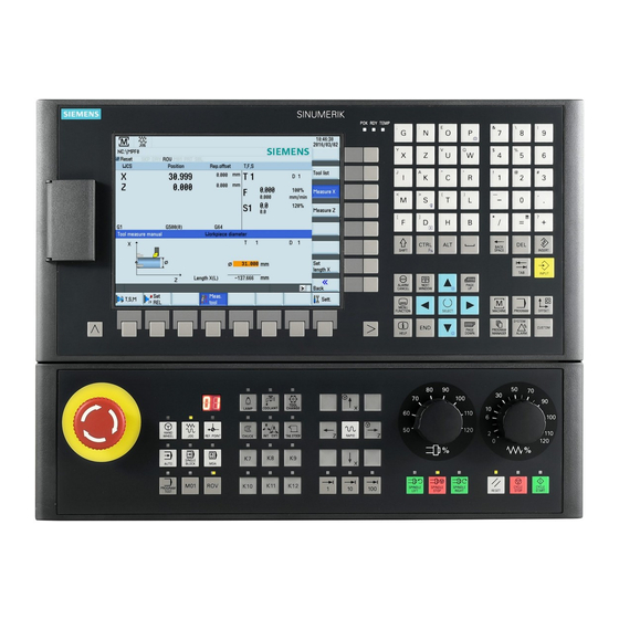
2.1.3 Screen layout Alarms and messages in the status area Displays active alarms with alarm text The alarm number is displayed in white lettering on a red background. The associated alarm text is shown in red letter- ing. An arrow indicates that several alarms are active. The number to the right of the arrow indicates the total number of active alarms. -
Page 12: Machine Control Panels (Mcps)
All MCP variants are applicable to any of the following con- trol systems: Horizontal MCP, with Chinese keys and override switch- • SINUMERIK 808D ADVANCED T (Turning) • Vertical MCP, with English keys and a reserved slot for • SINUMERIK 808D ADVANCED M (Milling) •... - Page 13 Vertical MCP • Variant with an override switch for the spindle • Variant with a reserved slot for the handwheel ① ⑨ Reserved hole for emergency stop button Spindle control keys ② ⑩ Tool number display Keys for program start, stop, and reset Displays the number of the currently active tool ③...
- Page 14 3. Print the final labeling strip template file on the blank plastic sheet. 4. Replace the pre-inserted labeling strips from the MCP with the customized ones. Note The MCP information described in this manual is valid for the SINUMERIK 808D MCP. Programming and Operating Manual (Turning) 01/2017...
-
Page 15: Coordinate Systems
Coordinate systems As a rule, a coordinate system is formed from three mutually perpendicular coordinate axes. The positive directions of the coordinate axes are defined using the Cartesian coordinate system. The coordinate system is related to the workpiece and programming takes place independently of whether the tool or the workpiece is being traversed. When programming, it is always assumed that the tool traverses relative to the coordinate system of the workpiece, which is intended to be stationary. -
Page 16: Protection Levels
The control system delivered by Siemens is set by default to the lowest protection level 7 (without password). If the password is no longer known, the control system must be reinitialized with the default machine/drive data. All passwords are then reset to default passwords for this software release. - Page 17 Changing/deleting the password Note To avoid unauthorized access to the controller, you must change the Siemens default passwords to your own ones. Select the system data operating area. If you desire to change the existing password, press this softkey to open the following win- dow and enter the new password: If you desire to delete the existing password, proceed directly to Step 6.
-
Page 18: Common Notices For Machining Operations
Press this softkey to confirm the new password. If you desire to delete the existing password, directly press this softkey. Common notices for machining operations To ensure the safety and correctness of machining, you must observe the following notices during machining operations: ●... -
Page 19: Setting The User Interface Language
Use the corresponding axis traversing keys to traverse the axes until the symbol appears next to the axis identifier. Setting the user interface language Note The default user interface language is dependent on the PPU type. For a PPU with Chinese keys, the default language is Chinese after power-on;... -
Page 20: Setting Up Tools
Setting up tools Creating a tool Note The control system supports a maximum of 64 tools and 128 cutting edges. You can create a maximum of nine cutting edges for each tool. Before executing a part program, you must first create the desired tool in the tool list and proceed with the tool setting operations. - Page 21 (MD19730[0] = 40000H). Note that MD19730 is visible only with the manufacturer password. Currently the clearance angle function can work only when the optional Manual Machine Plus function is licensed and activated. For more information about the clearance angle, see the SINUMERIK 808D/SINUMERIK 808D ADVANCED Function Manual. ④...
-
Page 22: Creating/Changing A Cutting Edge
Creating/changing a cutting edge Note Before creating or changing cutting edges, you must first create tools (Page 20). Operating sequence Select the offset operating area. Open the tool list window. Select the tool to which you desire to add a cutting edge. Open the menu items for cutting edge settings. -
Page 23: Activating The Tool And The Spindle
Activating the tool and the spindle Note A tool in the tool list is not active until you activate it in "MDA" mode or the "T, S, M" window. Operating sequence Select the machining operating area. Switch to "JOG" mode. Open the "T, S, M"... -
Page 24: Assigning The Handwheel
Assigning the handwheel If the machine manufacturer has assigned the handwheel for the control system, you can skip this section and directly measure the tool (Page 258) after activating the tool and the spindle (Page 23). This control system provides the following two methods for assigning the handwheel: ●... -
Page 25: Assigning The Handwheel Through The Ppu
6.4.2 Assigning the handwheel through the PPU Precondition Set MD14512[16].7 = 80 (default value: 0). With this setting, you can only assign the handwheel through the PPU. Operating sequence (activating the handwheel control function on the PPU) If this function is already active, skip the steps below and proceed directly to the operating sequence for assigning the handwheel through the PPU. -
Page 26: Measuring The Tool Manually
Press the desired vertical softkey (<X> ... <MZ1>) or this key for the handwheel assignment. The handwheel symbol which appears to the left of the selected axis (for example, the X axis) indicates that you have assigned the handwheel to the selected axis. Press the increment keys on the MCP to select the required override increment. - Page 27 Move the cursor to the input field for Length X with the cursor keys. Press this softkey or the alphabetic key <X> to open the window for measuring the tool in the X direction and enter the workpiece diameter in the input field (for example, 50). If you desire to use the relative coordinate, press this softkey.
-
Page 28: Measuring The Tool Manually (With The Y Axis)
If you have configured the Y axis and activated it, proceed through the steps below to measure axes X, Y and Z of the tool. For more information about how to configure the Y axis, see the SINUMERIK 808D/SINUMERIK 808D ADVANCED Commissioning Manual. - Page 29 Press this softkey to confirm your input. The system calculates the offset and enters it in the geometry input field of the currently active tool automatically. Measuring the Y axis of the tool Select the machining operating area. Switch to "MDA" mode and enter "SPOS=0" in the program editor window to fix the spindle. Switch to handwheel control mode.
- Page 30 If you desire to use the relative coordinate, press this softkey. Press this softkey to confirm your input. The system calculates the offset and enters it in the geometry input field of the currently active tool automatically. Measuring the Z axis of the tool Select the machining operating area.
-
Page 31: Verifying The Tool Offset Result
Press this softkey to confirm your input. The system calculates the offset and enters it in the geometry input field of the currently active tool automatically. Repeat the above steps to finish measuring all the tools. Verifying the tool offset result To guarantee the safety and correctness of machining, you must verify the tool setup result. -
Page 32: Creating Part Programs
Creating part programs Creating a part program The control system can store a maximum of 300 part programs which include those created by the control system for certain functions such as MM+, TSM, and so on. WARNING Danger to life and/or damage to machine due to insecure part programs Running an insecure part program on your machine may cause unexpected attacks to the machine, which in turn can lead to death, personal injuries, and/or machine damage. - Page 33 Press this softkey to open the window for creating a new program. Enter the name of the new program. You can enter the file name extension ".MPF" (main program) or ".SPF" (subprogram) to define the program type. The control system identifies a program as a main program if you do not enter any file name extension.
-
Page 34: Editing The Part Program
7.2.1 Using a standard program structure Using a standard program structure provides an easy way of part programming and a clear view of the machining sequences. Siemens recommends that you use the following program structure: 7.2.2 Editing a part program... - Page 35 Select the desired program file/directory in one of the following methods: Navigate to the program/directory with the cursor keys • Open the search dialog box and enter the desired search term. • Note: If you search for a program, the file name extension must be entered in the first input field of the dialog box below.
- Page 36 When necessary, select the following vertical softkeys to complete more program editing operations. Renumbering program blocks • With this softkey, you can modify the block numbering (Nxx) of a program opened in the program editor window. After you press this softkey, the block number is inserted at the beginning of the program block in ascending order and is increased by an increment of 10 (for example, N10, N20, N30).
-
Page 37: Understanding Frequently Used Programming Instructions
If you want to program cycles, press the corresponding softkey to open the desired cycle programming window. For more information, see Section "Cycles (Page 147)". If you want to program contours, press this softkey to open the contour programming win- dow. -
Page 38: Definition Of Work Offset (G54 To G59, G500, G90/G91)
7.2.3.2 Definition of work offset (G54 to G59, G500, G90/G91) Description Illustration Programming example G500: N10 G18 G90 G500 G71 All absolute path data corresponds to N20 T1 D1 the current position. The position val- N30 S5000 M3 G95 F0.3 ues are written in the G500 (basic) zero N40 G00 X50 Z5 offset. -
Page 39: Rapid Traverse (G00)
7.2.3.3 Rapid traverse (G00) Description Illustration Programming example G00: N10 G18 G90 G54 G71 When G00 is active in the program, the N20 T1 D1 axis will traverse at the maximum axis N30 S5000 M3 G95 F0.3 speed in a straight line. N40 G00 X50 Z5 N50 G01 Z-20 N60 Z5... -
Page 40: Turning Circles And Arcs (G02/G03)
For more information, see Sections "Tool radius compensation OFF: G40 (Page 121)" and "Selecting the tool radius compensation: G41, G42 (Page 118)". 7.2.3.6 Turning circles and arcs (G02/G03) The following gives an example of machining arc with specified program code: N10 G18 G90 G500 G71 N20 T1 D1 N30 S5000 M3 G95 F0.3... -
Page 41: Fixed Point Approach (G74/G75)
7.2.3.7 Fixed point approach (G74/G75) Description Programming example G74: N10 G18 G90 G500 G71 By using G74, reference point can be approached automati- N20 T1 D1 cally. N30 S5000 M3 G95 F0.3 N40 G00 X50 Z5 N50 G01 Z-5 N60 Z5 N70 G74 X=0 ;reference point G75: N10 G18 G90 G500 G71... -
Page 42: Program Simulation
Program simulation Simulation before machining Before automatic machining, you need to perform the simulation to check whether the tool moves in the right way. During simulation, the current program is calculated in its entirety and the result displayed in graphic form. The result of programming is verified without traversing the machine axes. - Page 43 You can also select the vertical softkeys as required in the simulation window as follows: Scales the entire simulation track automatically to adapt to the size of the window Zooms in the screen from the cursor position Zooms out the screen from the cursor position Deletes all the simulation tracks recorded up till now Makes the cursor move in large or small steps Enables the material removal simulation of a defined blank...
-
Page 44: Simultaneous Recording Prior To Machining Of The Workpiece
Simultaneous recording prior to machining of the workpiece Before machining the workpiece on the machine, you can graphically display the execution of the program on the screen to monitor the result of the programming. Operating sequence Select the program management operating area. Enter the target program directory and position the cursor on the desired program. -
Page 45: Machining The Workpiece
Machining the workpiece Executing a part program Before starting a program, make sure that both the control system and the machine are set up, and the part program is verified with simulation and test. Observe the relevant safety notes of the machine manufacturer. Select the program management operating area. -
Page 46: Executing Specified Blocks
Executing specified blocks If you would only like to perform a certain section of a program on the machine, then you do not need to start the program from the beginning. You can start the program from a specified program block in the following cases: ●... -
Page 47: Correcting A Part Program
Correcting a part program As soon as a syntax error in the part program is detected by the control system, program execution is interrupted and the syntax error is displayed in the alarm line. In this case, you can correct the error directly in the machining operating area with the program correction function. -
Page 48: Entering The Tool Wear Offsets
Entering the tool wear offsets Note You must distinguish the direction of tool wear compensation clearly. Two methods are available for entering the tool wear offsets: absolute input and incremental input (default: absolute input). Operating sequence for absolute input Select the offset operating area. Open the tool wear window. - Page 49 Enter the desired arithmetic statement in the input line of the pocket calculator. Press this key and the calculation result is displayed in the pocket calculator: Press this softkey to enter the result in the input field at the current cursor position and close the pocket calculator automatically.
- Page 50 Position the cursor bar on the input field to be modified. Switch to incremental input. Enter the desired increment value, for example, 0.1. Positive value: the tool compensates in a direction of moving away from the workpiece. • Negative value: the tool compensates in a direction of approaching the workpiece. •...
-
Page 51: Other Common Operations
Press this softkey to add the calculation result to the value in the input field at the current cursor position and close the pocket calculator automatically. Note: For more information about how to use the pocket calculator, see Section "Pocket calculator (Page 75)". -
Page 52: Conditional Stop
10.1.3 Conditional stop With this softkey activated, the processing of the program stops at the end of every block containing M01. In this way, you can check the result already obtained during the machining of a workpiece. This softkey functions the same as the following key on the MCP: Note that in order to continue executing the program, press the following key again: 10.1.4 Skip block... -
Page 53: Setting Up The Workpiece
10.2 Setting up the workpiece 10.2.1 Measuring the workpiece Overview Select the relevant offset panel (for example, G54) and the axis you want to determine for the offset. See the following example for how to determine the work offset in the Z axis. Before measuring, you can start the spindle by following the steps in Section "Activating the tool and the spindle (Page 23)". -
Page 54: Entering/Modifying Workpiece Offsets
Select the offset plane to save in (for example, G54). Enter the distance (for example, "0"). Press this key or move the cursor to confirm your input. Press this vertical softkey. The work offset of the Z axis is calculated automatically and displayed in the offset field. -
Page 55: Entering/Modifying The Setting Data
10.3 Entering/modifying the setting data Entering/modifying the setting data Operating sequence Select the offset operating area. Open the setting data window. Open the window for setting the general data. Position the cursor bar in the input fields to be modified and enter the values (see table below for the parameter descriptions). - Page 56 Parameters in the window for timers and workpiece counters ① The total number of workpieces produced (total actual) ② The number of workpieces required (workpiece setpoint) ③ The number of all workpieces produced since the starting time ④ The total run time of NC programs in "AUTO" mode and the run times of all programs between NC start and end of program/RESET.
- Page 57 Press this key to activate or deactivate the entered minimum/maximum values. Parameters in the window for working area limitation ① Displays the axes that exist in the machine coordinate system (MCS), workpiece coordinate system (WCS), or relative coordinate system (REL). ②...
-
Page 58: Setting R Parameters
Use this key or move the cursor to confirm your entries. 10.4 Setting R parameters Functionality The "R variables" start screen lists the R parameters that exist within the control system. You can set or query these global parameters in any program as required. Operating sequence Select the offset operating area. -
Page 59: Setting The Date And Time
10.6 Setting the date and time By default, the system date and time remain the factory settings. You can proceed through the following operating sequence to change the date and time as required. Operating sequence Select the system data operating area. Open the date and time setting window through the following softkey operations: →... -
Page 60: Transferring From External (Through Usb Interface)
To directly execute the program, press this softkey. The system automatically switches to "AUTO" mode in the machining operating area. The program is transferred to the buffer memory on the control system and then displayed in the following window: You can also press this key on the PPU to view the program blocks first before executing. Then press the following softkey to execute: If desired, you can use this softkey to specify how you want the program to be executed. -
Page 61: Executing/Transferring Through The Ethernet Connection
10.7.2 Executing/transferring through the Ethernet connection 10.7.2.1 Configuring the network drive A connected network drive allows you to access a shared directory on your computer from the control system. The network drive functions based on the Ethernet connection between the control system and a computer. The following Ethernet connections are possible: ●... - Page 62 Note: make sure this vertical softkey is not selected. Configure the network as required in the following window: You can configure the DHCP with this key. Note: if you select "No" for DHCP, you must enter the IP address (which must belong to the same network as that of your computer) and subnet mask manually.
-
Page 63: Executing From External (Through Ethernet Connection)
Move the cursor to the following input fields: ① : Enter the user name of your Windows account ② : Enter the logon password (case sensitive) of your Windows account ③ : Enter the IP address of the server and the share name of the shared directory on your computer. -
Page 64: Transferring From External (Through Ethernet Connection)
Press this softkey and the system automatically switches to "AUTO" mode in the machining operating area. The program is transferred to the buffer memory on the control system and then displayed in the following window: If desired, you can use this softkey to specify how you want the program to be executed. For more information of the program control, refer to Section "Program control functions (Page 51)"... -
Page 65: Executing/Transferring Through The Rs232 Interface (Ppu160.2 Only)
Communication tool - SinuComPCIN To enable the RS232 communication between a control system and a computer, you must have the RS232 communication tool SinuComPCIN installed on your computer. This tool is available in the SINUMERIK 808D/SINUMERIK 808D ADVANCED Toolbox. RS232 communication settings Proceed as follows to configure the communication settings for the RS232 interface: Connect the control system with the computer using an RS232 cable. -
Page 66: Executing From External (Through Rs232 Interface)
10.7.3.2 Executing from external (through RS232 interface) Prerequisites: ● The tool SinuComPCIN has been installed on your computer. ● The RS232 communication has been successfully established between the control system and the computer. Proceed as follows to execute a part program from external through the RS232 interface: Select the program management operating area. -
Page 67: Transferring From External (Through Rs232 Interface)
10.7.3.3 Transferring from external (through RS232 interface) Prerequisites: ● The tool SinuComPCIN has been installed on your computer. ● The RS232 communication has been successfully established between the control system and the computer. Note The program files can be transferred only to the system drive N:\MPF or N:\CMA; therefore, before transfer make sure the drive identifier contained in the first line in the program file is "N"... -
Page 68: Configuring The Firewall
10.7.4 Configuring the firewall Configuring the firewall Secure access and communication is achieved through the security function of the integrated firewall. You can open the window for firewall configuration through the following operations: → → → → Configurable ports are listed in the following window: The ports are disabled by default and can be enabled when necessary. - Page 69 Importing the activation/deactivation file Proceed through the following steps to import the file: To import the file via USB, store the file in a USB memory stick and insert the USB • memory stick into the USB interface at the front of the PPU. To import the file via Ethernet, store the file in a shared folder (network drive) on your •...
- Page 70 CNC lock function deactivated (with no lock date): • Note If an error occurs when importing the activation file, an error-specific alarm will be issued. The state of the CNC lock function remains unchanged. Note We recommend that you create a complete commissioning archive over all control system components after deactivating the CNC lock function.
-
Page 71: Data Backup
10.9 Data backup 10.9.1 Internal data backup You can save the NC and PLC data of the volatile memory to the permanent memory of the control system. Note After changing important data, it is recommended to carry out an internal data backup immediately. Backing up data internally Prerequisite: ●... -
Page 72: External Data Backup
Press this softkey to confirm. The control system restarts with the saved data. Note The following message is displayed on the screen after the control system starts up successfully with the saved data: You must enter the password again after you have powered up the control system with the saved data. 10.9.2 External data backup 10.9.2.1... -
Page 73: External Data Backup Of Separate Files
Press this softkey to confirm and the archive information dialog box opens. Specify the properties of the archive and press this softkey. The control system starts crea- tion of the startup archive. Note Do not remove the USB stick in the process of data backup if you choose USB as the target directory. Pressing <CTRL + S>... - Page 74 Press this vertical softkey in the RS232 window. The file transferring starts. Wait until SinuComPCIN finishes data transfer, and click this button. For more information about data backup, refer to the SINUMERIK 808D/SINUMERIK 808D ADVANCED Diagnostics Manual. Programming and Operating Manual (Turning)
-
Page 75: Pocket Calculator
10.10 Pocket calculator You can activate the calculator function by pressing this key on the PPU when you position the cursor on the desired input field to calculate the cycle relevant parameters, contour parameters, tool parameters, workpiece offsets, R parameters, etc. For calculating, the four basic arithmetic operations are available, as well as the functions "sine", "cosine", "squaring"... -
Page 76: Programming Principles
Calculation examples Task Input -> Result 100 + (67*3) 100+67*3 -> 301 sin(45_) 45 S -> 0.707107 cos(45_) 45 O -> 0.707107 4 Q -> 16 √4 4 R -> 2 (34+3*2)*10 (34+3*2)*10 -> 400 To calculate auxiliary points on a contour, the pocket calculator offers the following functions: ●... -
Page 77: Program Structure
11.1.2 Program structure Structure and content The NC program consists of a sequence of blocks (see the table below). Each block represents a machining step. Instructions are written in the blocks in the form of words. The last block in the execution sequence contains a special word for the end of the program, for example, M2. -
Page 78: Absolute/Incremental Dimensioning: G90, G91, Ac, Ic
11.2.2 Absolute/incremental dimensioning: G90, G91, AC, IC Functionality With the instructions G90/G91, the written positional data X, Z, ... are evaluated as a coordinate point (G90) or as an axis position to traverse to (G91). G90/91 applies for all axes. Irrespective of G90/G91, certain positional data can be specified for certain blocks in absolute/incremental dimensions using AC/IC. -
Page 79: Dimensions In Metric Units And Inches: G71, G70, G710, G700
11.2.3 Dimensions in metric units and inches: G71, G70, G710, G700 Functionality If workpiece dimensions that deviate from the base system settings of the control system are present (inch or mm), the dimensions can be entered directly in the program. The required conversion into the base system is performed by the control system. - Page 80 See the following diameter and radius dimensioning for the traverse axis: Programming examples Diameter dimensions (DIMON) DIAMON ; Diameter dimensions active G1 X0 Z0 F0.2 ; Traverse to diameter position X0 and Z0 X20 CHF=2 Z-17 X30 Z-20 Z-40 X40 Z-45 Z-70 ;...
-
Page 81: Programmable Work Offset: Trans, Atrans
11.2.5 Programmable work offset: TRANS, ATRANS Functionality The programmable work offset can be used: ● for recurring shapes/arrangements in various positions on the workpiece ● when selecting a new reference point for the dimensioning ● as a stock allowance when roughing This results in the current workpiece coordinate system. - Page 82 Programming example 2 G90 G18 G500 T3D1 M4S1500 G0X50 Z10 CYCLE95( "CON1:CON1_E", 0.50000, 0.20000, 0.20000, ,0.20000, 0.20000, 0.15000, 9, , ,2.00000) M4S1200 G0X100Z-10 R0=46 LAB1: TRANS X=R0 Z-25 AROT RPL=-10 R1=-45 R2=14 R3=34 LAB: TRANS X=R0 Z-25 AROT RPL=10 R5=R2*COS(R1) R6=R3*SIN(R1) G1 Z=R5 X=R6 R1=R1-0.5...
-
Page 83: Programmable Scale Factor: Scale, Ascale
R0=29 TRANS Z-52 X=R0 DIAMOF R4=720 R1=(3.14159*R4)/180 R2=SIN(R4) G1 X=R2 Z=R1 R4=R4-0.5 IF R4>=0 GOTOB LL DIAMON R0=R0-0.5 IF R0>=27 GOTOB BB G0X80 ;*************CONTOUR************ CON1: X42Z0 X54Z-13 Z-60 CON1_E:;************* CONTOUR ENDS ************ 11.2.6 Programmable scale factor: SCALE, ASCALE Functionality A scale factor can be programmed for all axes with SCALE, ASCALE. The path is enlarged or reduced by this factor in the axis specified. -
Page 84: Workpiece Coordinate System- Settable Work Offset: G54 To G59, G500, G53, G153
See the following example of a programmable scale factor: Programming example N10 L10 ; Programmed contour original N20 SCALE X2 Z2 ; contour in X and Z enlarged 2 times N30 L10 N40 ATRANS X2.5 Z1.8 N50 L10 N60 M30 Subroutine call - see Section "Subroutine technique (Page 131)". -
Page 85: Linear Interpolation
See the following illustration for settable work offset: Programming example N10 G54 G0 X50 Z135 N20 X70 Z160 N30 T1 D1 N40 M3 S1000 N50 G0 X20 Z130 N60 G01 Z150 F0.12 N70 X50 F0.1 N80 G500 X100 Z170 N90 M30 11.3 Linear interpolation 11.3.1... -
Page 86: Feedrate F
Programming example N10 G0 X100 Z65 Note Another option for linear programming is available with the angle specification ANG=. (For more information, see Section "Contour definition programming (Page 112)".) Information Another group of G functions exists for moving into the position (see Section "Exact stop/continuous-path control mode: G9, G60, G64 (Page 98)"). -
Page 87: Linear Interpolation With Feedrate: G1
11.3.3 Linear interpolation with feedrate: G1 Functionality The tool moves from the starting point to the end point along a straight path. For the path velocity, is determined by the programmed F word. All the axes can be traversed simultaneously. G1 remains active until canceled by another instruction from this G group (G0, G2, G3...). - Page 88 The description of the desired circle can be given in various ways: G2/G3 remains active until canceled by another instruction from this G group (G0, G1...). The path velocity is determined by the programmed F word. Programming G2/G3 X... Y... I... J... ;...
- Page 89 Programming example: Definition of center point and end point N5 G90 Z30 X40 ; Starting point circle for N10 N10 G2 Z50 X40 K10 I-7 ; End point and center point Note Center point values refer to the circle starting point! Programming example: End point and radius specification N5 G90 Z30 X40 ;...
- Page 90 Programming example: Definition of end point and aperture angle N5 G90 Z30 X40 ; Starting point circle for N10 N10 G2 Z50 X40 AR=105 ; Opening angle and end point Programming example: Definition of center point and aperture angle N5 G90 Z30 X40 ;...
-
Page 91: Circular Interpolation Via Intermediate Point: Cip
11.4.2 Circular interpolation via intermediate point: CIP Functionality The direction of the circle results here from the position of the intermediate point (between starting and end points). Specification of intermediate point: I1=... for the X axis, K1=... for the Z axis. CIP remains active until canceled by another instruction from this G group (G0, G1...). -
Page 92: Thread Cutting
11.5 Thread cutting 11.5.1 Thread cutting with constant lead: G33 Functionality The function G33 can be used to machine threads with constant lead of the following type: ● Thread on cylindrical structures ● Thread on tapered structures ● External thread ●... - Page 93 See the following illustration for lead assignment for cylindrical, tapered and face thread: Tapered thread For tapered threads (2 axis values required), the corresponding lead address I or K of the axis with the larger travel (longer thread) must be used. A second lead is not defined. Starting point offset SF= A starting point offset is required for the spindle if a multiple-start thread or a thread in offset sections is to be machined.
-
Page 94: Programmable Run-In And Run-Out Path For G33: Dits, Dite
See the following example of multi-block thread chaining: Axis velocity When cutting threads with G33, you can determine the axis velocity based on the spindle speed and the thread lead. However, the maximum axis velocity (rapid traverse) defined in the machine data cannot be exceeded; otherwise, alarms will appear. -
Page 95: Thread Cutting With Variable Lead: G34, G35
See the following illustration for run-in/run-out path for G33: Programming example N10 G54 N20 G90 G0 Z100 X10 M3 S500 N30 G33 Z50 K5 SF=180 DITS=4 DITE=2 ; run-in 4 mm, run-out 2 mm N40 G0 X30 N50 G0 X100 Z100 N60 M5 N70 M30 11.5.3... -
Page 96: Thread Interpolation: G331, G332
Programming G34 Z... K... F... ;Cylindrical thread with increasing lead G35 X... I... F... ;Face thread with decreasing lead G35 Z... X... K... F... ;Taper thread with decreasing lead Programming example N10 M3 S40 ; Spindle CW N20 G0 G54 G90 G64 Z10 X60 ;... -
Page 97: Fixed Point Approach
11.6 Fixed point approach 11.6.1 Fixed point approach: G75 Functionality By using G75, a fixed point on the machine, e.g. tool change point, can be approached. The position is stored permanently in the machine data for all axes. A maximum of four fixed points can be defined for each axis. No offset is effective. -
Page 98: Acceleration Control And Exact Stop/Continuous Path
11.7 Acceleration control and exact stop/continuous path 11.7.1 Exact stop/continuous-path control mode: G9, G60, G64 Functionality G functions are provided for optimum adaptation to different requirements to set the traversing behavior at the block borders and for block advancing. For example, you would like to quickly position with the axes or to machine contours over multiple blocks. - Page 99 N20 X20 Z0 ;G60 continues to act N30 X30 Z-40 N40 M3 S1000 N50 G1 G601 X35 Z-50 F0.12 ; Exact stop window fine N60 G64 Z-65 ;Switching over to continuous-path mode N70 X40 Z-70 N80 G0 G9 Z-80 ; Exact stop acts only in this block N90 X45 Z-90 ;Again continuous-path mode N100 M30...
-
Page 100: Acceleration Pattern: Brisk, Soft
11.7.2 Acceleration pattern: BRISK, SOFT BRISK The axes of the machine change their velocities using the maximum permissible acceleration value until reaching the final velocity. BRISK allows time-optimized working. The set velocity is reached in a short time. However, jumps are present in the acceleration pattern. -
Page 101: The Third Axis
Remark G4 S.. is only possible if a controlled spindle is available (if the speed specifications are also programmed via S...). 11.8 The third axis Prerequisite The control system itself must be designed for three axes. Functionality Depending on the machine design, the third axis can be required. These axes can be implemented as linear or rotary axes. The identifier for these axes is defined by the machine manufacturer (e.g. -
Page 102: Spindle Positioning
Information If you write M3 or M4 in a block with axis movements, the M commands become active before the axis movements. Standard setting: Axis movements will only start once the spindle has accelerated to speed (M3, M4). M5 is also issued before the axis movement. - Page 103 The program advances to the next block if the end of motion criteria for the spindle or axes programmed in the current block plus the block change criterion for path interpolation are fulfilled. Synchronization In order to synchronize spindle movements, can be used to wait until the spindle position is reached.
- Page 104 End of motion on reaching "interpolator stop" IPOENDA A block change is possible in the braking ramp. IPOBRKA : Channel axis identifier <axis> : Instant in time of the block change with reference to the braking ramp <instant in time> Unit: Percent Range of values: 100 (application point of the braking ramp) to 0 (end of the braking ramp) If a value is not assigned to the...
- Page 105 Example 2: Spindle positioning in axis mode Program variant 1: N10 G0 X100 Z100 N20 M3 S500 N30 G0 X80 Z80 N40 G01 X60 Z60 F0.25 N50 SPOS=0 Position control on, spindle 1 positioned to 0, axis mode can be used in the next block.
- Page 106 Example 3: Drill cross holes in turned part Cross holes are to be drilled in this turned part. The running spindle is stopped at zero degrees and then successively turned through 90°, stopped and so on. G0 X100 Z100 N110 S2=1000 M2=3 Switch on cross drilling attachment.
-
Page 107: Spindle Positioning (Spos, Sposa, M19, M70, Waits): Further Information
11.9.2.2 Spindle positioning (SPOS, SPOSA, M19, M70, WAITS): Further information Further information Positioning with SPOSA The block step enabling or program execution is not affected by SPOSA. The spindle positioning can be performed during execution of subsequent NC blocks. The program moves onto the next block if all the functions (except for spindle) programmed in the current block have reached their block end criterion. -
Page 108: Gear Stages
There is no difference between dimensioning. In both cases, rotation continues in the direction selected by until the absolute end position is reached. With , deceleration takes place if necessary, and the appropriate approach direction is taken. With , the spindle rotates additionally to the specified value starting at the current spindle position. - Page 109 Remark: If G94 instead of G95 was active before, a new appropriate F value must be written. See the following illustration for constant cutting rate G96: Rapid traverse With rapid traverse G0, there is no change in speed. Exception: If the contour is approached at rapid traverse and the next block contains an interpolation type G1 or G2, G3, CIP, CT (contour block), then the speed for the contour block is applied already in the approach block with G0.
-
Page 110: Rounding, Chamfer
11.10.2 Rounding, chamfer Functionality You can insert the chamfer (CHF or CHR) or rounding (RND) elements into a contour corner. If you wish to round several contour corners sequentially by the same method, use "Modal rounding" (RNDM). You can program the feedrate for the chamfer/rounding with FRC (non-modal) or FRCM (modal). If FRC/FRCM is not programmed, the normal feedrate F is applied. - Page 111 Chamfer CHF or CHR A linear contour element is inserted between linear and circle contours in any combination. The edge is broken. See the following illustration for inserting a chamfer with CHF using the example: between two straight lines. See the following illustration for inserting a chamfer with CHR using the example: Between two straight lines. Programming examples of chamfer N10 G0 X100 Z100 G94 F100 N20 G1 X80 CHF=5...
-
Page 112: Contour Definition Programming
Rounding RND or RNDM A circle contour element can be inserted with tangential connection between the linear and circle contours in any combination. See the following illustration for examples for inserting roundings: Programming examples for rounding N10 G0 X100 Z100 G94 F100 N20 G1 X80 RND=8 ;... - Page 113 See the following illustration for angle value for determination of a straight line: See the following illustration for examples of multi-block contours: Programming and Operating Manual (Turning) 01/2017...
-
Page 114: Tool And Tool Offset
11.11 Tool and tool offset 11.11.1 General information (turning) Functionality During program creation for the workpiece machining, you do not have to take tool lengths or cutting radius into consideration. You program the workpiece dimensions directly, e.g. according to the drawing. The tool data must be entered separately in a special data area. -
Page 115: Tool Offset Number D (Turning)
11.11.3 Tool offset number D (turning) Functionality It is possible to assign 1 to 9 data fields with different tool offset blocks (for multiple cutting edges) to a specific tool. If a special cutting edge is required, then it can be programmed using D and the appropriate number. If a D word is not written, D1 is automatically effective. - Page 116 The following figures provide information on the required tool parameters for the respective tool type. See the following illustration for turning tool with two cutting edges D1 and D2_length compensation: Programming and Operating Manual (Turning) 01/2017...
- Page 117 See the following illustration for compensations for turning tool with tool radius compensation: See the following illustration for effect of the compensation for the drill: Center hole Switch to G17 for application of a center hole. This makes the length compensation take effect for the drill in the Z axis. After drilling, the normal compensation for turning tools takes effect again with G18.
-
Page 118: Selecting The Tool Radius Compensation: G41, G42
Programming example N10 T3 D1 ;Drill N20 G17 G1 F1 Z0 M3 S100 ; Tool length offset effective in Z axis N30 Z-15 N40 G18 M30 ; Drilling terminated 11.11.4 Selecting the tool radius compensation: G41, G42 Functionality A tool with a corresponding D number must be active. The tool radius offset (cutting edge radius offset) is activated by G41/G42. - Page 119 See the following illustration for compensation to the right/left of the contour: Starting the compensation The tool approaches the contour on a straight line and positions itself vertically to the path tangent in the starting point of the contour. Select the start point so as to ensure collision-free traversing. See the following illustration for start of the tool radius compensation with the example G42: The tool tip goes around the left of the workpiece when the tool runs clockwise using G41;...
-
Page 120: Corner Behavior: G450, G451
11.11.5 Corner behavior: G450, G451 Functionality Using the functions G450 and G451, you can set the behavior for non-continuous transition from one contour element to another contour element (corner behavior) when G41/G42 is active. Internal and external corners are detected automatically by the control system. For internal corners, the intersection of the equidistant paths is always approached. -
Page 121: Tool Radius Compensation Off: G40
11.11.6 Tool radius compensation OFF: G40 Functionality The compensation mode (G41/G42) is deselected with G40. G40 is also the switch-on position at the beginning of the program. The tool ends the block before G40 in the normal end position (compensation vector vertical to the tangent in the end point); independently of the start angle. -
Page 122: Example Of Tool Radius Compensation (Turning)
Cancellation of compensation by M2 If the offset mode is canceled with M2 (program end) without writing the command G40, the last block with coordinates ends in the normal offset vector setting. No compensating movement is executed. The program ends with this tool position. Critical machining cases When programming, pay special attention to cases where the contour path for inner corners is smaller than the tool radius;... -
Page 123: Special Handling Of Tool Compensation (Turning)
11.11.9 Special handling of tool compensation (turning) Influence of setting data With the use of the following setting data, the operator/programmer can influence the calculation of the length compensation of the tool used: ● SD 42940: TOOL_LENGTH_CONST (Assignment of tool-length components to geometry axes) ●... -
Page 124: H Function
Note The M function interrupts the G64 continuous path mode and generates exact stop. Programming example N10 S1000 N20 G1 X50 F0.1 M3 ;M function in the block with axis movement, spindle acceler- ates before the X axis movement N180 M78 M67 M10 M12 M37 ;Max. - Page 125 Value assignments You can assign values in the following range to the R parameters: ±(0.000 0001 ... 9999 9999) (8 decimal places, arithmetic sign, and decimal point) The decimal point can be omitted for integer values. A plus sign can always be omitted. Example: R0=3.5678 R1=-37.3 R2=2 R3=-7 R4=-45678.123 Use the exponential notation to assign an extended range of numbers:...
-
Page 126: Local User Data (Lud)
N100 R[R1]=27.123 ;Indirectly assign R5 the value 27.123 11.14.2 Local User Data (LUD) Functionality The operator/programmer (user) can define his/her own variable in the program from various data types (LUD = Local User Data). These variables are only available in the program in which they were defined. The definition takes place immediately at the start of the program and can also be associated with a value assignment at the same time. -
Page 127: Reading And Writing Plc Variables
11.14.3 Reading and writing PLC variables Functionality To allow rapid data exchange between NC and PLC, a special data area exists in the PLC user interface with a length of 512 bytes. In this area, PLC data are compatible in data type and position offset. In the NC program, these compatible PLC variables can be read or written. -
Page 128: Conditional Program Jumps
See the following illustration for an example of unconditional jumps: 11.15.2 Conditional program jumps Functionality Jump conditions are formulated after the IF instruction. If the jump condition (value not zero) is satisfied, the jump takes place. The jump destination can be a block with a label or with a block number. This block must be located within the program. Conditional jump instructions require a separate block. -
Page 129: Program Example For Jumps
Programming example for comparison operators R1>1 ;R1 greater than 1 1 < R1 ;1 less than R1 R1<R2+R3 ;R1 less than R2 plus R3 R6>=SIN( R7*R7) ; R6 greater than or equal to SIN (R7) squared Programming example N10 IF R1 GOTOF LABEL1 ;If R1 is not null then go to the block having LABEL1 G0 X30 Z30 N90 LABEL1: G0 X50 Z50... -
Page 130: Jump Destination For Program Jumps
See the following illustration for linear approach of points on a circle segment: Programming example N10 R1=30 R2=32 R3=10 R4=11 R5=50 R6=20 ;Assignment of initial values N20 MC1: G0 Z=R2*COS (R1)+R5 X=R2*SIN(R1)+R6 ;Calculation and assignment to axis addresses N30 R1=R1+R3 R4= R4-1 N40 IF R4 >... -
Page 131: Subroutine Technique
11.16 Subroutine technique 11.16.1 General information Usage Basically, there is no difference between a main program and a subroutine. Frequently recurring machining sequences are stored in subroutines, e.g. certain contour shapes. These subroutines are called at the appropriate locations in the main program and then executed. One form of a subroutine is the machining cycle. -
Page 132: Calling Machining Cycles (Turning)
Please make sure that the values of your arithmetic parameters used in upper program levels are not inadvertently changed in lower program levels. When working with SIEMENS cycles, up to 7 program levels are needed. 11.16.2 Calling machining cycles (turning) Functionality Cycles are technology subroutines that realize a certain machining process. -
Page 133: Executing Internal And External Subroutines (Call, Extcall)
11.16.3 Executing internal and external subroutines (CALL, EXTCALL) Function ● With the command, you can reload and execute programs stored in the NC directory. CALL ● With the command, you can reload and execute programs stored on an external USB memory stick. EXTCALL Machine data and setting data The following machine data and setting data is used for the... -
Page 134: Timers And Workpiece Counters
Note Internal and external subroutines must not contain jump statements such as , or GOTOF GOTOB CASE LOOP WHILE REPEAT constructions are possible. IF-ELSE-ENDIF Subroutine calls and nested calls may be used. CALL EXTCALL RESET, POWER ON RESET and POWER ON can cause the interruption of internal and external subroutine calls. Examples ●... - Page 135 It is automatically reset in the case of a system power-up with default values. ● $AN_POWERON_TIME Time since the last system power-up (in minutes) It is reset to zero automatically after each power-up of the control system. Timers that can be activated machine data The following timers are activated via machine data (default setting).
-
Page 136: Workpiece Counter
Display The content of the active system variables is visible in the window opened through the following key operations: → → Window display: ① ⑤ = $AC_TOTAL_PARTS = $AC_CYCLE_TIME ② ⑥ = $AC_REQUIRED_PARTS = $AC_CUTTING_TIME ③ ⑦ =$AC_ACTUAL_PARTS = $AN_SETUP_TIME $AC_SPECIAL_PARTS is not available for display. - Page 137 ● $AC_TOTAL_PARTS Total number of workpieces produced (total actual) The counter specifies the total number of all workpieces produced since the start time. The counter is set to zero upon every booting of the control system automatically. ● $AC_ACTUAL_PARTS Number of actual workpieces (actual) This counter registers the number of all workpieces produced since the starting time.
-
Page 138: Kinematic Transformation
You can also select whether to activate the workpiece counter function through the following key operations: → → 11.18 Kinematic transformation 11.18.1 Face milling on turned parts (TRANSMIT) Function The TRANSMIT function enables the following: ● Face machining on turned parts in the turning clamp (drill-holes, contours). ●... - Page 139 Rotary axis The rotary axis cannot be programmed as it is occupied by a geometry axis and thus cannot be programmed directly as channel axis. Meaning TRANSMIT: Activates the first declared TRANSMIT function. This function is also designated as polar transformation. TRAFOOF: Deactivates an active transformation.
-
Page 140: Cylinder Surface Transformation (Tracyl)
Program code Comment N230 SETMS(1) ; Set the first spindle back N240 G0 X20 Z10 SPOS=45 ; Approach the starting position N250 M30 Description Pole There are two ways of passing through the pole: ● Traverse the linear axis alone ●... - Page 141 ● If the machine has a real machine Y-axis(YM), an expanded TRACYL variant can also be configured. This allows grooves with groove wall offset to be produced: the groove wall and base are perpendicular to each other - even if the milling tool's diameter is smaller than the groove width.
- Page 142 Note Set OFFN=0 once the groove has been completed. OFFN is also used outside of TRACYL - for offset programming in combination with G41, G42. Example: Tool definition The following example is suitable for testing the parameterization of the TRACYL cylinder transformation: Program code Comment Tool parameters...
- Page 143 Example: Making a hook-shaped groove Activate cylinder surface transformation: Required tool: T1 milling tool, radius=3 mm, edge position=8. Program code Comment N10 T1 D1 G54 G90 G94 ; Tool selection, clamping compensation F1000 N20 SPOS=0 ; Approach the starting position N30 SETMS(2) ;...
- Page 144 The linear axes are positioned perpendicular to one another. The infeed axis cuts the rotary axis. With groove wall offset (transformation type 513) Kinematics as above, but an additional longitudinal axis parallels to the peripheral direction. The linear axes are positioned perpendicular to one another. The velocity control makes allowance for the limits defined for the rotations.
- Page 145 Certain machine data settings are assumed for the part program and the assignment of the corresponding axes in the BCS or MCS. For more information, see the SINUMERIK 808D/SINUMERIK 808D ADVANCED Function Manual. Offset contour normal OFFN (transformation type 513) To mill grooves with TRACYL, the following is programmed: ●...
- Page 146 A part program for milling a groove generally comprises the following steps: 1. Selecting a tool 2. Select TRACYL 3. Select suitable coordinate offset (frame) 4. Positioning 5. Program OFFN 6. Select TRC 7. Approach block (position TRC and approach groove side) 8.
-
Page 147: Cycles
Cycles 12.1 Overview of cycles Cycles are generally applicable technology subroutines that you can use to carry out a specific machining process, such as tapping. These cycles are adapted to individual tasks by parameter assignment. Drilling cycles and turning cycles You can carry out the following standard cycles by using the control system: ●... -
Page 148: Graphical Cycle Programming In The Program Editor
Basic instructions with regard to the assignment of standard cycle parameters Each defined parameter of a cycle has a certain data type. The parameter being used must be specified when the cycle is called. The following can be transferred in the parameter list: ●... -
Page 149: Drilling Cycles
Enter the values directly (numerical values) or indirectly (R parameters, for example, R27, or expressions consisting of R parameters, for example, R27 + 10). If numerical values are entered, the control system will automatically perform a check to see whether the value lies within the permitted range. Use this key to select values for some parameters that may have only a few values for se- lection. -
Page 150: Requirements
See the following illustration for geometrical parameters: 12.4.2 Requirements Call and return conditions Drilling cycles are programmed independently of the actual axis names. The drilling position must be approached in the higher-level program before the cycle is called. The required values for feedrate, spindle speed and direction of spindle rotation must be programmed in the part program if there are no defining parameters in the drilling cycle. - Page 151 Dwell time programming The parameters for dwell times in the drilling cycles are always assigned to the F word and must therefore be assigned with values in seconds. Any deviations from this procedure must be expressly stated. Special features when using drilling cycles on a turning machine Simple turning machines without driven tools can apply drilling cycles only for drilling on the end face (with Z-axis) in the turning center.
-
Page 152: Drilling, Centering - Cycle81
● The spindle of the driven tool must be declared to the master spindle (SETMS command). ● The drilling position can be programmed either with Z and the C-axis or, if TRACYL is active, with X and Z. See the following illustration for drilling on peripheral surface with a driven tool: 12.4.3 Drilling, centering - CYCLE81 Programming... - Page 153 Explanation of the parameters RFP and RTP (reference plane and retraction plane) Normally, reference plane (RFP) and return plane (RTP) have different values. The cycle assumes that the retraction plane precedes the reference plane. This means that the distance from the retraction plane to the final drilling depth is larger than the distance from the reference plane to the final drilling depth.
-
Page 154: Drilling, Counterboring - Cycle82
Programming example: Drilling_centering This program produces three drill holes using the CYCLE81 drilling cycle. The drilling axis is always the Z axis. See the following example for drilling centering_drilling on turning center without tool: N10 G0 G17 G90 F200 S300 M3 ;... - Page 155 ● Dwell time at final drilling depth ● Retraction to the retraction plane with G0 Explanation of the parameters For an explanation of the parameters RTP, RFP, SDIS, DP, and DPR, see Section "Drilling, centering - CYCLE81 (Page 152)". See the following parameters for CYCLE82: DTB (dwell time) The dwell time to the final drilling depth (chip breakage) is programmed under DTB in seconds.
-
Page 156: Deep-Hole Drilling - Cycle83
Confirm your settings with this softkey. The cycle is then automatically transferred to the program editor as a separate block. 12.4.5 Deep-hole drilling - CYCLE83 Programming CYCLE83 (RTP, RFP, SDIS, DP, DPR, FDEP, FDPR, DAM, DTB, DTS, FRF, VARI, AXN, MDEP, VRT, DTD, DIS1) Parameters Parameter Data type... - Page 157 Parameter Data type Description REAL Dwell time at starting point and for chip removal Values: >0: in seconds <0: in revolutions REAL Feedrate factor for the first drilling depth (enter without sign) Range of values: 0.001 ... 1 VARI Machining type: Chip breakage=0, Chip removal=1 Tool axis (values: 1 = 1st geometrical axis;...
- Page 158 Deep-hole drilling with chip breakage (VARI=0): ● Approaching to a position of safety distance relative to the reference plane with G0 ● Traversing to the first drilling depth with G1, the feedrate for which is derived from the feedrate defined with the program call which is subject to parameter FRF (feedrate factor) ●...
- Page 159 ● From the second drilling depth on, the drilling stroke is obtained by subtracting the amount of degression from the stroke of the last drilling depth, provided that the latter is greater than the programmed amount of degression. ● The next drilling strokes correspond to the amount of degression, as long as the remaining depth is greater than twice the amount of degression.
-
Page 160: Rigid Tapping - Cycle84
The limit distance is calculated within the cycle as follows: ● Up to a drilling depth of 30 mm, the value is set to 0.6 mm. ● For larger drilling depths, the limit distance is the result of (RFP + SDIS - current depth) / 50. If this calculated value >7, a limit of 7 mm, maximum, is applied. Programming example: Deep-hole drilling This program executes the cycle CYCLE83 at the position X0. - Page 161 Function The tool drills at the programmed spindle speed and feedrate to the entered final thread depth. CYCLE84 can be used to make tapped holes without compensating chuck. For tapping with compensating chuck, a separate cycle CYCLE840 is provided. Note CYCLE84 can be used if the spindle to be used for the boring operation is technically able to be operated in the position- controlled spindle operation.
- Page 162 MPIT and PIT (thread lead as a thread size and as a value) The value for the thread lead can be defined either as the thread size (for metric threads between M3 and M48 only) or as a value (distance from one thread turn to the next as a numerical value). Any parameters not required are omitted in the call or assigned the value zero.
- Page 163 Note The direction of rotation when tapping in the cycle is always reversed automatically. Programming example 1: Rigid tapping A thread is tapped without compensating chuck at position X30 Y35 in the XY plane; the tapping axis is the Z axis. No dwell time is programmed;...
-
Page 164: Tapping With Compensating Chuck - Cycle840
Confirm your settings with this softkey. The cycle is then automatically transferred to the program editor as a separate block. 12.4.7 Tapping with compensating chuck - CYCLE840 Programming CYCLE840 (RTP, RFP, SDIS, DP, DPR, DTB, SDR, SDAC, ENC, MPIT, PIT, AXN) Parameters Parameter Data type... - Page 165 Function The tool drills at the programmed spindle speed and feedrate to the entered final thread depth. You use this cycle to perform tapping with the compensating chuck: ● without encoder ● with encoder Sequence Tapping with compensating chuck without encoder Position reached prior to cycle start: The drilling position is the position in the two axes of the selected plane.
- Page 166 Explanation of the parameters For an explanation of the parameters RTP, RFP, SDIS, DP, and DPR, see Section "Drilling, centering - CYCLE81 (Page 152)". DTB (dwell time) The dwell time must be programmed in seconds. It is only effective in tapping without encoder. SDR (direction of rotation for retraction) SDR=0 must be set if the spindle direction is to reverse automatically.
- Page 167 AXN (tool axis) The following figure presents the options for the drilling axes to be selected. With G18: ● AXN=1 ;Corresponds to Z ● AXN=2 ;Corresponds to X ● AXN=3 ;Corresponds to Y (if Y axis is present) See the following illustration for drilling axis of G18: Using AXN (number of the drilling axis) to program the drilling axis enables the drilling axis to be directly programmed.
-
Page 168: Reaming1 - Cycle85
omitted. N50 M2 ; End of program Programming example: Tapping with encoder This program is used for tapping with encoder at position X0. The drilling axis is the Z axis. The lead parameter must be defined, automatic reversal of the direction of rotation is programmed. A compensating chuck is used in machining. N10 G90 G0 G54 D1 T6 S500 M3 ;... - Page 169 The cycle creates the following sequence of motions: ● Approaching the position of safety distance relative to the reference plane with G0 ● Traversing to the final drilling depth with G1 and at the feedrate programmed under the parameter FFR ●...
-
Page 170: Boring - Cycle86
The feedrate value programmed under RFF is active when retracting from the hole to the reference plane + safety clearance. Programming example: First boring pass CYCLE85 is called at Z70 X0. The drilling axis is the Z axis. The value for the final drilling depth in the cycle call is programmed as a relative value;... - Page 171 Explanation of the parameters For the explanation of the parameters RTP, RFP, SDIS, DP, and DPR, see Section "Drilling, centering - CYCLE81 (Page 152)". See the following parameters for CYCLE86: DTB (dwell time) The dwell time to the final drilling depth (chip breakage) is programmed under DTB in seconds. SDIR (direction of rotation) With this parameter, you determine the direction of rotation with which boring is performed in the cycle.
-
Page 172: Turning Cycles
N10 G0 G90 X0 Z100 SPOS=0 ; Approach start position N15 SETMS(2) ; Master spindle is now the milling spindle N20 TRANSMIT ; Activate TRANSMIT function N35 T10 D1 ; Load tool N50 G17 G0 G90 X20 Y20 ; Drilling position N60 S800 M3 F500 N70 CYCLE86(112, 110, , 77, 0, 2, 3, -1, 0, 1, ;... - Page 173 Contour monitoring relative to the clearance angle of the tool Certain turning cycles in which traversing motions with relief cutting are generated monitor the clearance angle of the active tool for a possible contour violation. This angle is entered in the tool compensation as a value (in the D offset under the parameter DP24).
-
Page 174: Cutoff - Cycle92
12.5.2 Cutoff - CYCLE92 Programming CYCLE92 (SPD, SPL, DIAG1, DIAG2, RC, SDIS, SV1, SV2, SDAC, FF1, FF2, SS2, 0, VARI, 1, 0, AMODE) Parameters Parameter Data type Description REAL Starting point along facing axis (absolute, always diameter) REAL Starting point in the longitudinal axis (absolute) DIAG1 REAL Depth for speed reduction ∅... - Page 175 Sequence 1. The tool first moves to the starting point calculated internally in the cycle at rapid traverse. 2. The chamfer or radius is machined at the machining feedrate. 3. Cut-off down to depth DIAG1 is performed at the machining feedrate. 4.
-
Page 176: Groove - Cycle93
12.5.3 Groove - CYCLE93 Programming CYCLE93 (SPD, SPL, WIDG, DIAG, STA1, ANG1, ANG2, RCO1, RCO2, RCI1, RCI2, FAL1, FAL2, IDEP, DTB, VARI, _VRT) Parameters Parameter Data type Description REAL Starting point along facing axis REAL Starting point along longitudinal axis WIDG REAL Groove width (enter without sign) - Page 177 Step 2 The groove is machined vertically to the infeed direction in one or several steps whereby each step, in turn, is divided according to the infeed depth. From the second cut along the groove width onwards, the tool will retract by 1 mm before each retraction.
- Page 178 Step 4 Stock removal of the finishing allowance parallel to the contour from the edge to the groove center. During this operation, the tool radius compensation is selected and deselected by the cycle automatically. Explanation of parameters SPD and SPL (starting point) These coordinates can be used to define the starting point of a groove starting from which the form is calculated in the cycle.
- Page 179 WIDG and DIAG (groove width and groove depth) The parameters groove width (WIDG) and groove depth (DIAG) are used to define the form of the groove. In its calculation, the cycle always assumes the point programmed under SPD and SPL. If the groove width is larger than that of the active tool, the width is removed in several steps.
- Page 180 The form of the groove can be modified by entering radii/chamfers at the margin or at the base. It is imperative to enter the radii with positive sign, and the chamfers with negative sign. FAL1 and FAL2 (finishing allowance) It is possible to program separate finishing allowances for groove base and flanks. During roughing, stock removal is carried out up to these finishing allowances.
- Page 181 If the parameter has a different value, the cycle will abort with alarm 61002 "Machining type defined incorrectly". The cycle carries out a contour monitoring such that a reasonable groove contour results. This is not the case if the radii/chamfers come into contact or intersect at the groove base or if you try to carry out a face grooving operation at a contour segment located parallel to the longitudinal axis.
- Page 182 Programming example 2 Select the program editing operating area. Open the vertical softkey bar for available turning cycles. Press this softkey to open the window for CYCLE93. Parameterize the cycle as desired. Confirm your settings with this softkey. The cycle is then automatically transferred to the program editor as a separate block.
-
Page 183: Undercut (Forms E And F To Din) - Cycle94
N10 G0 G90 Z100 X100 T5 D1 S400 M3 ;Starting point before the beginning of the cycle N20 G95 F0.2 ; Specification of technology values N30 CYCLE93(70, 60, 30, 25, 5, 20, 10, 0, 0, -2, - ; Cycle call 2, 1, 1, 5, 1, 5,0.2) Retraction distance of 0.2 mm programmed N40 G0 G90 X100 Z100... - Page 184 ● Selection of the cutter radius compensation according to the active tool point direction and traveling along the undercut contour at the feedrate programmed prior to the cycle call ● Retraction to the starting point with G0 and deselection of the cutter radius compensation with G40 Explanation of the parameters SPD and SPL (starting point) Use the parameter SPD to specify the finished part diameter for the undercut.
- Page 185 VARI=0: According to tool point direction The tool point direction is determined by the cycle automatically from the active tool compensation. The cycle can operate with the tool point directions 1 ... 4. If the cycle detects any of the tool point directions 5 ... 9, the alarm 61608 "Wrong tool point direction programmed" and the cycle is aborted.
-
Page 186: Cutting With Relief Cut - Cycle95
Programming example: Undercut form E This program can be used to program an undercut of form E. N10 T1 D1 S300 M3 G95 F0.3 ; Specification of technology values N20 G0 G90 Z100 X50 ; Selection of starting position N30 CYCLE94(20, 60, "E",) ;... - Page 187 When the contour is machined through finishing and roughing, finishing is performed in the same direction as roughing, dependent on the setting of the VARI parameter; however, if the contour is machined through finishing only, the direction of machining is determined by the programmed direction, independent of the setting of the VARI parameter. The tool radius compensation can be selected (G41/G42) and deselected (G40) via the following USER DATA: ●...
- Page 188 Roughing the relief cut elements: ● Approach of the starting point for the next relief cut axis by axis with G0 When doing so, an additional cycle-internal safety clearance is observed. ● Infeed along the contour + finishing allowance with G1/G2/G3 and FF2. ●...
- Page 189 ● Defining the contour as a subroutine NPP = name of the subroutine – If the subroutine already exists, specify a name, and then continue. – If the subroutine does not yet exist, specify a name and then press the following softkey: A program with the entered name is created and the program automatically jumps to the contour editor.
- Page 190 total depth of a roughing section and of the programmed maximum infeed depth to which the total depth to be machined is distributed equally. This provides optimum cutting conditions. For roughing this contour, the machining steps shown in the illustration result. See the following illustration for the example of infeed depth: Machining section 1 has a total depth of 39 mm.
- Page 191 VARI (machining type) The machining type can be found in the table below. Value Longitudinal/face Ext./int. Roughing/finishing/complete Roughing Roughing Roughing Roughing Finishing Finishing Finishing Finishing Complete machining Complete machining Complete machining Complete machining In longitudinal machining, the infeed is always carried out along the transversal axis, and in face machining - along the longitudinal axis.
- Page 192 DT and DAM (dwell time and path length) These parameters can be used to achieve an interruption of the individual roughing steps after certain distances traversed in order to carry out chip breaking. These parameters are only relevant for roughing. The parameter DAM is used to define the maximum distance after which chip breaking is to be carried out.
- Page 193 _VRT (lift-off distance) Parameter _VRT can be used to program the amount by which the tool is retracted in both axes when roughing. For _VRT=0 (parameter not programmed), the tool will retract by 1 mm. Contour definition The contour must contain at least 3 blocks with motions in the two axes of the machining plane. If the contour program is too short, the cycle is aborted after the alarms 10933 "Number of contour blocks contained in the contour program not sufficient"...
- Page 194 If a tool radius compensation is programmed in the contour subroutine with G41/G42, the cycle is canceled, and alarm 10931 "Faulty cutting contour" is issued. Contour direction The direction in which the stock removal contour is programmed can be freely selected. In the cycle, the machining direction is defined automatically.
- Page 195 Starting point The cycle determines the starting point for the machining operation automatically. The starting point is located in the axis in which the depth infeed is carried out, shifted from the contour by the amount of the finishing allowance + lift-off distance (parameter _VRT).
- Page 196 The following is the main program: N10 T1 D1 G0 G95 S500 M3 Z125 X81 ; Approach position before cycle call N20 CYCLE95("CONTOUR_1", 5, 1.2, 0.6, , 0.2, 0.1, 0.2, 9, , ; Cycle call , 0.5) N30 G0 G90 X81 ;Reapproach starting position N40 Z125 ;...
- Page 197 N110 G18 DIAMOF G90 G96 F0.8 N120 S500 M3 N130 T1 D1 N140 G0 X70 N150 Z160 N160 CYCLE95("START:END",2.5,0.8, 0.8,0,0.8,0.75,0.6,1, , , ; Cycle call N170 G0 X70 Z160 N175 M02 START: N180 G1 X10 Z100 F0.6 N190 Z90 N200 Z70 ANG=150 N210 Z50 ANG=135 N220 Z50 X50 END:...
- Page 198 Press one of the following two softkeys. The program automatically jumps to the program editor screen form. If you desire to edit and store the contour in a subroutine, press this softkey. If you desire to edit and store the contour as a section of a main program, press this softkey. Note: For more information about programming in the contour editor, see Section "Free contour programming (Page 269)".
- Page 199 G01X-2F0.15 G0X50 Z100 G0X50Z10 M4S1500 G1F0.2 CYCLE95( "CON01", 0.50000, 0.20000, 0.20000, 0.20000, 0.20000, 0.20000, 0.10000, 1, , ,1.00000) G0X55 Z100 M3S1500 G0X50Z10 CYCLE95( "CON02:CON02_E", 0.50000, 0.20000, 0.20000, 0.20000, 0.20000, 0.20000, 0.10000, 5, , ,1.00000) ;*************CONTOUR************ CON02: ;#7__DlgK contour definition begin - Don't change!;*GP*;*RO*;*HD* G18 G90 DIAMON;*GP* G0 Z0 X0 ;*GP* G1 X28 CHR=3 ;*GP*...
-
Page 200: Thread Undercut - Cycle96
CON02_E:;************* CONTOUR ENDS ************ 12.5.6 Thread undercut - CYCLE96 Programming CYCLE96 (DIATH, SPL, FORM, VARI) Parameters Parameter Data type Description DIATH REAL Nominal diameter of the thread REAL Starting point of the correction in the longitudinal axis FORM CHAR Definition of the form Values: A (for form A), B (for form B), C (for form C), D (for form D) VARI Specification of undercut position... - Page 201 Explanation of the parameters DIATH (nominal diameter) Use this cycle to perform thread undercuts for metric threads from M3 through M68. If the value programmed in DIATH results in a final diameter of <3 mm, the cycle is aborted and alarm: 61601 "Finished part diameter too small"...
- Page 202 If the parameter has a value other than A ... D, the cycle aborts and creates alarm 61609 "Form defined incorrectly". Internally in the cycle, the tool radius compensation is selected automatically. The cycle only uses the tool point directions 1 ... 4. If the cycle detects a tool point direction 5 ... 9 or if the form of the undercut cannot be machined with the selected tool point direction, alarm 61608 "Wrong tool point direction programmed"...
-
Page 203: Thread Chaining - Cycle98
N10 D3 T1 S300 M3 G95 F0.3 ; Specification of technology values N20 G0 G90 Z100 X50 ; Selection of starting position N30 CYCLE96 (42, 60, "A",) ; Cycle call N40 G90 G0 X100 Z100 ; Approach next position N50 M2 ;... - Page 204 Parameter Data type Description REAL Thread lead 2 as a value (enter without sign) REAL Thread lead 3 as a value (enter without sign) VARI Definition of the machining type for the thread Range of values: 1 ... 4 NUMTH Number of threads (enter without sign) _VRT REAL...
- Page 205 Explanation of the parameters PO1 and DM1 (starting point and diameter) These parameters are used to define the original starting point for the thread series. The starting point determined by the cycle itself and approached at the beginning using G0 is located by the run-in path before the programmed starting point. PO2, DM2 and PO3, DM3 (intermediate point and diameter) These parameters are used to define two intermediate points in the thread.
- Page 206 By using parameter IANG, the angle is defined under which the infeed is carried out in the thread. If you wish to infeed at a right angle to the cutting direction in the thread, the value of this parameter must be set to zero. This means that the parameter can be omitted in the parameter list, as in this case the value is defaulted automatically with zero.
- Page 207 Value Ext./int. Const. Infeed/const. cutting cross-section External Constant infeed Internal Constant infeed External Constant cutting cross-section Internal Constant cutting cross-section If a different value is programmed for the VARI parameter, the cycle is aborted after output of alarm 61002 "Machining type defined incorrectly".
-
Page 208: Thread Cutting - Cycle99
N10 G95 T5 D1 S1000 M4 ; Specification of technology values N20 G0 X40 Z10 ; Approach starting position N30 CYCLE98 (0, 30, -30, 30, -60, 36, -80, 50, 10, 10, ; Cycle call 0.92, , , , 5, 1, 1.5, 2, 2, 3, 1,) N40 G0 X55 ;... - Page 209 Parameter Data type Description VARI Definition of the machining type for the thread (values: 300101 = external thread with linear infeed; 300102 = internal thread with linear infeed; 300103 = external thread with degressive infeed; 300104 = internal thread with degressive infeed) NUMTH Number of threads (enter without sign) _VRT...
- Page 210 Note To use this cycle, the spindle must be equipped with an encoder. Sequence Position reached prior to cycle start: Starting position is any position from which the programmed thread starting point and run-in path can be approached without collision. The cycle creates the following sequence of motions: ●...
- Page 211 When the thread depth is divided into infeeds with constant cutting cross-section, the cutting force will remain constant over all roughing cuts. In this case, the infeed will be performed using different values for the infeed depth. A second version is the distribution of the whole thread depth to constant infeed depths. When doing so, the cutting cross- section becomes larger from cut to cut, but with smaller values for the thread depth, this technology can result in better cutting conditions.
- Page 212 Use the NUMTH parameter to define the number of thread turns with a multiple-turn thread. For a single-turn thread, the parameter must be assigned zero or ignored directly. The thread turns are distributed equally over the circumference of the turned part; the first thread turn is determined by the NSP parameter.
- Page 213 10 = face thread: 20 = taper thread: Programming and Operating Manual (Turning) 01/2017...
- Page 214 Programming example: Thread cutting By using this program, you can produce a metric external thread M42x2 with flank infeed. Infeed is carried out with constant cutting cross-section. At the end of thread a cut out of 7 mm is defined. 5 roughing cuts are carried out at a thread depth of 2.76 mm without finishing allowance.
-
Page 215: Error Messages And Error Handling
12.6 Error messages and error handling 12.6.1 General Information If error conditions are detected in the cycles, an alarm is generated and the execution of the cycle is aborted. Furthermore, the cycles display their messages in the message line of the control system. These messages will not interrupt the program execution. -
Page 216: Machining Typical Turning Parts
Machining typical turning parts 13.1 Operations before programming Operating sequence Turn on the power supply for the machine tool. Proceed with the operations for the refer- ence point approach, if the machine axis is equipped with an incremental encoder (see Chapter "Switching on and referencing (Page 18)"). - Page 217 • Cut the workpiece manually after machining is over. • Operating sequence for programming in Siemens mode Select the program management operating area. Press this softkey to enter the system directory for storing part programs. Press this softkey and enter the name of the new program.
- Page 218 Open the vertical softkey bar for available turning cycles. Press this softkey to open the window for CYCLE95 and enter the name of the contour subroutine in "NPP", for example, "RR". Press this softkey to open the program editor window again and enter the program blocks for the external contour: G1 X0 Z0 G3 X33.762 Z-30.726 CR=20...
- Page 219 Operating sequence for programming in ISO mode Select the system data operating area. Press this softkey and the system prompts the following window: Press this softkey and control system automatically starts the mode change from Siemens mode to ISO mode. Select the program management operating area.
- Page 220 Press this softkey to enter the system directory for storing part programs. Press this softkey and enter the name of the new program. Press this softkey to confirm your entry. The part program editor window opens automatical- Enter the following program: G291 T0202 G0 X100 Z100...
-
Page 221: Programming For Machining Contours (Example 2)
• Cut the workpiece manually after machining is over. • Operating sequence for programming in Siemens mode Select the program management operating area. Press this softkey to enter the system directory for storing part programs. Press this softkey and enter the name of the new program. - Page 222 Press this softkey to confirm your entry. The part program editor window opens automatical- Enter the following program in the window. The control system saves your editing automati- cally. Open the vertical softkey bar for available turning cycles. Press this softkey to open the window for CYCLE95 and enter the name of the contour subroutine in "NPP", for example, "WW".
- Page 223 Press this softkey to open the program editor window again and enter the program blocks for the external contour: G0 Z0 X0 G1 X10 RND=1 Z-12 X5 Z-16 X20 Z-31 X10 Z-33 X19 Z-35 X25 RND=3 Z-40 Z-48 X15 X19 RND=1 Z-50 Z-54 X15 Z-60...
- Page 224 Move the cursor to "C" in the line for CYCLE95 with the cursor keys and press this softkey to insert a marker. Use the cursor keys to select the entire program block for CYCLE95. Press this softkey to copy the selection to the buffer memory. Place the cursor on the end-of-block character after "M3 S2000"...
- Page 225 Operating sequence for programming in ISO mode Select the system data operating area. Press this softkey and the system prompts the following window: Press this softkey and control system automatically starts the mode change from Siemens mode to ISO mode. Select the program management operating area.
- Page 226 Press this softkey to confirm your entry. The part program editor window opens automatical- Programming and Operating Manual (Turning) 01/2017...
- Page 227 Enter the following program: G291 T0202 M3 S1000 G0 X100 Z100 G0 X45 Z3 G71 U2 R1 G71 P10 Q20 U0.15 W0 F0.2 N10 G0 X0 Z3 G1 Z0 G3 X10 Z-1 R1 G1 Z-2 Z-12 X5 Z-16 X20 Z-31 X10 Z-33 X19 Z-35 G3 Z-38 X25 R3...
-
Page 228: Programming For Roughing, Grooving And Threading (Example 3)
13.4 Programming for roughing, grooving and threading (Example 3) Workpiece drawing (unit: mm) Coordinates of key machining points Point X coordinate Z coordinate 25.596 -35.868 34.722 -39.987 44.000 -44.974 44.000 -48.624 30.000 -50.500 30.000 -55.500 44.000 -57.376 Blank data Blank material: aluminum bar Blank diameter: 45 mm Blank length: 100 mm (machining limit along the Z axis: Z-68;... - Page 229 Operating sequence for programming in Siemens mode Select the program management operating area. Press this softkey to enter the system directory for storing part programs. Press this softkey and enter the name of the new program. Press this softkey to confirm your entry. The part program editor window opens automatical- Enter the following program in the window.
- Page 230 Press this softkey to open the program editor window again and enter the program blocks for the external contour: G1 X0 Z0 X20 CHF=1.5 Z-20 X25.596 Z-35.868 G2 X34.722 Z-39.987 CR=5 G3 X44 Z-44.974 CR=5 G1 Z-68 Note: Make sure you enter the blank diameter in the last line of the program for the external con- tour (for example, "X45"...
- Page 231 Press this key to change the value to "5". Press this softkey to accept the change and continue to enter the following program blocks: G0 X100 Z100 T3 D1 M3 S600 G0 X100 Z100 Z-20 G1 X17 F0.1 X20 F0.5 G0 X50 Open the vertical softkey bar for available turning cycles.
- Page 232 Open the window for CYCLE99. Enter the desired parameters as follows: Note: Set the parameters visible only with the scroll bar to their default values. Continue to enter the following program blocks: G0 X100 Z100 Then you can proceed with the operations for "program simulation and execution (Page 242)".
- Page 233 Operating sequence for programming in ISO mode Select the system data operating area. Press this softkey and the system prompts the following window: Press this softkey and control system automatically starts the mode change from Siemens mode to ISO mode. Select the program management operating area.
- Page 234 Press this softkey to confirm your entry. The part program editor window opens automatical- Enter the following program: G291 T0101 M3 S1000 G0 X100 Z100 G0 X46 Z3 G71 U2 R1 G71 P10 Q20 U0.15 W0.1 F0.2 N10 G0 X0 Z3 G1 Z0 X20 Z-1.5 Z-20...
- Page 235 G1 X30 F0.1 G0 X46 Z-54.73 G1 X30 F0.1 G0 X46 Z-58.38 G1 X44 F0.1 X41.67 Z-57.01 X31.48 Z-55.7 G3 X30 Z-54.73 R1 G1 Z-54.7 G0 X46 Z-50.21 G1 X44 F0.1 X42.07 Z-51.88 X31.48 Z-53.3 G2 X30 Z-54.27 R1 G1 Z-54.3 G0 X46 G0 X100 Z100 T0404...
-
Page 236: Programming For Roughing And Finishing (Example 4)
• Cut the workpiece manually after machining is over. • Operating sequence for programming in Siemens mode Select the program management operating area. Press this softkey to enter the system directory for storing part programs. Press this softkey and enter the name of the new program. - Page 237 Press this softkey to confirm your entry. The part program editor window opens automatical- Enter the following program in the window. The control system saves your editing automati- cally. Open the vertical softkey bar for available turning cycles. Press this softkey to open the window for CYCLE95 and enter the name of the contour subroutine in "NPP", for example, "LL".
- Page 238 Press this softkey to return to the window for CYCLE95 and enter the desired parameters as follows: Press this softkey to confirm your input and open the cycle programming window. Enter the following program block below the program line for CYCLE95: M3 S1000 Press this softkey to return to the program editor window.
- Page 239 Open the window for CYCLE99. Enter the desired parameters as follows: Note: Set the parameters visible only with the scroll bar to their default values. Continue to enter the following program blocks: G0 X0 Z150 Then you can proceed with the operations for "program simulation and execution (Page 242)".
- Page 240 Press this softkey and control system automatically starts the mode change from Siemens mode to ISO mode. Select the program management operating area. Press this softkey to enter the system directory for storing part programs. Press this softkey and enter the name of the new program.
- Page 241 Enter the following program: G291 T0101 M3 S800 G0 X0 Z150 X18 Z3 G71 U2 R1 G71 P10 Q20 U-0.2 W0.05 F0.2 N10 G0 X70 Z3 G1 Z0 X60 Z-10 X50.5 X48.5 Z-11 Z-30 X40 Z-35 Z-40 G3 X20 Z-50 R10 N20 G1 Z-61 M3 S1000 G70 P10 Q20 F0.1...
-
Page 242: Program Simulation And Execution
13.6 Program simulation and execution Switch to "AUTO" mode. Press this softkey to open the program simulation window, and the program control mode PRT is automatically activated. Press this key to start the simulation for the the selected part program. After you finish the simulation, you can press this softkey to return to the program editor window. -
Page 243: A Appendix
Appendix Operating area overview A.1.1 Machining operating area Pressing this key on the PPU allows you to open the window for the machining operating area. You can perform reference point approach, tool setting operations, as well as program start, stop, control, block search, and real- time simulation, etc. -
Page 244: Offset Operating Area
⑥ Opens the program simulation window to check the programming results before machining ⑦ Recompiles the current cycle or contour selected with cursor by reopening the previous programming window ⑧ Executes the current program ⑨ Automatically assigns block numbers (Nxx) to all blocks ⑩... -
Page 245: Program Management Operating Area
Softkey Function See also ⑧ Creates a new tool "Creating a tool (Page 20)" ⑨ Opens a lower-level menu for cutting edge settings "Creating/changing a cutting edge (Page 22)" ⑩ Removes the currently selected tool from the tool list ⑪ Searches for your desired tool with the tool number A.1.4 Program management operating area... - Page 246 ⑫ Selects all files for the subsequent operations ⑬ Copies the selected file(s) to the clipboard ⑭ Pastes the selected file(s) from the clipboard to the current directory ⑮ Restores the deleted file(s) ⑯ Opens the lower-level menu for more options: Rename the part programs •...
- Page 247 Copying, cutting, and pasting programs Select the program management operating area. Open the desired directory. Select the program file that you would like to copy or cut. Perform either of the following operations as desired: Press this softkey to copy the selected file: •...
- Page 248 Renaming programs Select the program management operating area. Open the desired directory. Select the program file that you would like to rename. Press the extension softkey. Press this vertical softkey to open the window for renaming. Enter a desired new name with the extension in the input field. Press this softkey to confirm your entry.
-
Page 249: System Data Operating Area
A.1.5 System data operating area Softkey functions Pressing this key combination allows you to enter the system data operating area. This operating area includes functions required for parameterizing and analyzing the NCK, the PLC, and the drive. The start screen displays the machine configuration data and softkeys available. Depending on the functions se- lected, the horizontal and the vertical softkey bars vary. -
Page 250: Alarm Operating Area
Views and manages the alarm log ⑦ Configures the access right for the remote control through the Ethernet connection. For more information about the softkey function, see the SINUMERIK 808D/SINUMERIK 808D ADVANCED Commissioning Manual. Programming and Operating Manual (Turning) 01/2017... -
Page 251: Operating Mode Overview
Operating mode overview A.2.1 "AUTO" mode Overview The machine must have been set up for "AUTO" mode according to the specifications of the machine manufacturer. You can perform such operations as program start, stop, control, block search, and real-time simulation and recording, etc. Softkey functions Pressing this key in the machining operating area switches to "AUTO"... -
Page 252: Jog" Mode
Parameters ① Displays the axes that exist in the machine coordinate system (MCS), workpiece coordinate system (WCS), or relative coordinate system (REL). ② Displays the current position of the axes in the selected coordinate system. ③ Displays the remaining distance for the axes to traverse. ④... - Page 253 ④ Opens the "Manual Machine Plus" user interface. This softkey is visible only if this software option is pre-configured by the machine manufacturer. For more information about this window, see the Manual Machine Plus (MM+), Turning Manual. ⑤ Opens the settings window where you can set JOG feedrate and variable increment values. For more information, see Section "Setting the JOG data (Page 256)".
-
Page 254: Running The Spindle Manually
A.2.2.1 Running the spindle manually Note Before running the spindle manually, make sure you have activated the tool. Operating sequence Select the machining operating area. Switch to "JOG" mode. Press this key on the MCP to rotate the spindle counter-clockwisely. Press this key on the MCP to stop the spindle rotation. -
Page 255: Executing M Functions
A.2.2.2 Executing M functions Note Before executing M functions, make sure all the axes are in safe positions. Operating sequence Select the machining operating area. Switch to "JOG" mode. Open the "T, S, M" window. Press this key to move the cursor to the input field for M functions, and enter the desired value, for example, "8". -
Page 256: Setting The Jog Data
You can use the corresponding vertical softkeys to set the reference point to zero. Sets the X axis to zero Sets the Z axis to zero Sets the spindle to zero Sets all axes to zero A.2.2.4 Setting the JOG data Operating sequence Select the machining operating area. -
Page 257: Mda" Mode
A.2.3 "MDA" mode Basic softkey functions in "MDA" mode This window displays important G functions whereby each G function is assigned to a group and has a fixed position in the window. To close the window, press this softkey once again. To display additional G functions, use the corresponding keys. -
Page 258: Additional Method For Measuring The Tool
Additional method for measuring the tool Note You must first create a tool (Page 20) and activate it (Page 23) before measuring the tool. • This section takes the turning tool measurement for example. If you have created other types of tools, proceed through •... -
Page 259: Activating The Contour Handwheel Via The Nc Program
"AUTO" or "MDA" mode. This section only introduces how to activate the contour handwheel via the NC program. For how to activate this function via the PLC interfaces, see the SINUMERIK 808D/SINUMERIK 808D ADVANCED Function Manual. Preconditions ●... - Page 260 Activating the contour handwheel in "AUTO" mode Open the desired NC program in the part program editor window. For more information about how to create or edit a part program, see Chapter "Creating part programs (Page 32)". Enter the mandatory instructions "G1" (or "G2"/"G3"), "G94", "G60" and "FD=0" in the blocks.
-
Page 261: The Help System
Machine data or setting data selected • V70 data selected • ② Calls the machine manufacturer-developed PDF manual ③ Displays all available help information: Siemens help manuals • Machine manufacturer-developed help manuals, if any • All available NC/V70 alarms • All available V70 parameters •... - Page 262 Softkeys in Window "①" Use this softkey to select cross references A cross reference is marked by the characters "≫ ... ≪" . Note: This softkey is displayed only if the current page contains a cross reference. Searches for a term in the current topic Continues search for the next term that matches the search criteria Exits the help system Softkeys in Window "②"...
-
Page 263: Operation Wizard
Searches for a term in the current topic Continues search for the next term that matches the search criteria Exits the help system Operation wizard The operation wizard provides step-by-step guides on basic commissioning and operation procedures. Operating sequence Call the operation wizard through the following key operations: →... -
Page 264: Editing Chinese Characters
Editing Chinese characters The program editor and PLC alarm text editor both allow you to edit the simplified Chinese characters on the Chinese variant of the HMI. Editing simplified Chinese characters Press the following key combination to switch the editor on or off: Press this key to toggle between different input methods. -
Page 265: Calculating Contour Elements
Calculating contour elements Function You can use the calculator to calculate the contour elements in the respective input fields. Calculating a point in a circle Activate the calculator when you position the cursor on the desired input field. Open the lower-level menu for contour elements selection. Select the desired calculation function. - Page 266 Example ① ② Calculating the point of intersection between the circle sector and the straight line in plane G18: Given: ● Radius: 10 ● Circle center point CC: Z=147 X=183 (diameter programming) ● Connection angle for straight lines: -45° Result: Z = 154.071, X = 190.071 The result appears on the input screen.
- Page 267 Enter the following coordinates or angles in the respective input fields: Coordinates of the given point (PP) • Slope angle of the straight line (A1) • Distance of the new point with reference to PP • Slope angle of the connecting straight line (A2) with reference to A1 •...
- Page 268 Press this softkey to define the given end point when the abscissa value is given. Press this softkey to define the second straight line which is rotated counter-clockwise by 90 degrees against the first straight line. Press this softkey to define the second straight line which is rotated clockwise by 90 de- grees against the first straight line.
-
Page 269: Free Contour Programming
Result: Z = -19.499, X = 60 Free contour programming Functionality Free contour programming enables you to create simple and complex contours. A contour editor (FKE) calculates any missing parameters for you as soon as they can be obtained from other parameters. You can link together contour elements and transfer to the edited part program. - Page 270 Recompile When the program edited in the contour editor is opened in the program editor, if you position the editor cursor in a command line of the contour program and then press this softkey, the main screen of the contour editor opens and you can recompile the existing contour. Note When recompiling, only the contour elements that were generated in the contour editor are created again.
-
Page 271: Defining A Start Point
A.9.1 Defining a start point When entering a contour, begin at a position which you already know and enter it as the starting point. Operating sequence Select the program management operating area. Press this softkey to enter the system directory for storing part programs. Select the desired program file, and press this key to open it in the program editor. -
Page 272: Programming Contour Element
A.9.2 Programming contour element Functionality Once you have defined the contour start point, press this softkey and you can begin programming the individual contour elements from the main screen shown below: ① Opens the window for programming a vertical straight line (in X direction) ②... - Page 273 Input switchover This softkey is displayed only in cases where the cursor is positioned on an input field with several switchover settings. Selecting dialog Some parameter configurations can produce several different contour characteristics. In such cas- es, you will be asked to select a dialog. By clicking this softkey, you can display the available selec- tion options in the graphic display area.
- Page 274 Inserting a contour element Use the cursor keys in the contour chain to select the contour element in front of the position for the new element. Then select the contour element to be inserted from the softkey bar. After you have configured the parameters for the new contour element, confirm the insert operation by pressing the following softkey: Subsequent contour elements are updated automatically according to the new contour status.
-
Page 275: Parameters For Contour Elements
A.9.3 Parameters for contour elements Parameters for programming straight lines ① Absolute (abs)/incremental (inc) end position in X or Z direction ② Transition element to the next contour is a chamfer (CHR) or a radius (RND). CHR=0 or RND=0 means no transition element. - Page 276 Parameters for programming circular arcs ① Direction of rotation of the circular arc: clockwise or counter-clockwise ② Radius of circle ③ Absolute (abs)/incremental (inc) end positions in X and Z directions ④ Absolute (abs)/incremental (inc) positions of circle center point in X (I) and Z (K) directions ⑤...
- Page 277 Radius or chamfer at the start or the end of a turning contour: In simple turning contours a chamfer or radius must often be appended at the start and end of the contour. A chamfer or radius terminates an axis-parallel contour section on the blank: You select the direction of transition for the contour start in the starting point screen.
-
Page 278: Undercuts For Turning Technology
A.9.4 Undercuts for turning technology Supplementary conditions The form E and F undercut and form DIN 76 and general thread undercut functions are only activated when the turning technology is enabled. Form E and F undercuts as well as thread undercuts are available only if level G18 is set. Undercuts are permitted only on contour edges of the rotational body, which run in the direction of the longitudinal axis (usually parallel to the Z axis). - Page 279 This softkey allows you to specify a pole and can only be entered in absolute Cartesian coordi- nates. This softkey is also present in the starting point screen. This enables the pole to be entered at the start of a contour, so that the first contour element can be entered in polar coordinates. Further notes If the straight line that was generated with close contour is linked to the start element of the contour with a radius or chamfer, the radius or chamfer must be specified explicitly as follows:...
- Page 280 Pole change example Pole: Zpole = 0.0, Xpole = 0.0, (Pole 0) End point: L1abs = 10.0 ϕabs = 30.0° Calculated Cart. Coordinates Zabs = 8.6603 Xabs = 5.0 New pole: Zpole1 = 5.0 Xpole1 = 5.0 (Pole 1) Calculated polar coord. Predecessor L1abs = 3.6603 ϕabs = 0.0°...
-
Page 281: Cycle Support
A.9.6 Cycle support Functionality The following technologies are provided with additional support in the form of pre-defined cycles, which then must be parameterized. ● Drilling ● Turning For more information, see Chapter "Cycles (Page 147)". A.9.7 Programming example for turning application Example 1 The following diagram shows a programming example for the "Free contour programming"... - Page 282 Define a start point with the following parameters and press this softkey to confirm. Programming mode: DIAMOF • Z: 0 • X: 0 • Press this softkey to select a contour element of straight vertical line. Enter the parameters for this element and press this softkey to confirm. X: 20 inc.
- Page 283 Press this softkey to select a contour element of straight vertical line. Enter the parameters for this element and press this softkey to confirm. X: 5 inc. • Press this softkey to select a contour element of straight horizontal line. Enter the parameters for this element and press this softkey to confirm.
- Page 284 Press this softkey to open the contour editor. Define a start point with the following parameters and press this softkey to confirm. Programming mode: DIAMON • Z: 0 • X: 0 • Press this softkey to select a contour element of straight vertical line. Enter the parameters for this element and press this softkey to confirm.
-
Page 285: Word Structure And Address
Press this softkey to select a contour element of straight vertical line. Enter the parameters for this element and press this softkey to confirm. X: 92 abs. • CHR: 3 • Now you can see the programmed contour in the graphics window: A.10 Word structure and address Functionality/structure... -
Page 286: Character Set
Several address characters A word can also contain several address letters. In this case, however, the numerical value must be assigned via the intermediate character "=". Example: CR=5.23 Additionally, it is also possible to call G functions using a symbolic name. For more information, see Section "List of instructions (Page 288)". -
Page 287: Block Format
A.12 Block format Functionality A block should contain all data required to execute a machining step. Generally, a block consists of several words and is always completed with the end-of-block character " L " (Linefeed). When writing a block, this character is automatically generated when pressing the linefeed key on an externally connected keyboard or pressing the following key on the PPU: See the following block structure diagram: Word order... -
Page 288: List Of Instructions
Programming example ; G&S company, order no. 12A71 ; Pump part 17, drawing no.: 123 677 ; Program created by H. Adam, Dept. TV 4 N40 MSG("DRAWING NO.: 123677") :50 G54 F4.7 S220 D2 M3 ;Main block N60 G0 G90 X100 Z200 N70 G1 Z185.6 N80 X112 /N90 X118 Z180... - Page 289 Address Significance Value assign- Information Programming ments Circular interpolation clockwise G2 X... Z... I... K... F... ;End point and center point G2 X... Z... CR=... F... ;Radius and end point G2 AR=... I... K... F... ;opening angle and center point G2 AR=...
- Page 290 Address Significance Value assign- Information Programming ments G332 Thread interpolation - retraction G332 Z... K... ;tapping without compensating chuck, e.g. in Z axis, retraction motion ; sign of lead as for G331 Dwell time 2: Special motions, dwell time, G4 F...;separate block, F: non-modal Time in seconds G4 S..
- Page 291 24: Feedforward control, modally effective FFWON Feedforward control ON DIAMOF Radius dimensioning 29: Dimension radius/diameter, modally effective DIAMON * Diameter dimensioning G290 * SIEMENS mode 47: External NC languages, modally effective G291 External mode Programming and Operating Manual (Turning) 01/2017...
- Page 292 Address Significance Value assign- Information Programming ments H function ± 0.0000001 ... Value transfer to the PLC; H0=... H9999=... 9999 9999 significance defined by the ma- (8 decimal places) chine manufacturer e.g.: H7=23.456 or specified as an H9999= exponent: ± (10-300 ... 10+300 ) Interpolation parame- ±0.001 ...
- Page 293 Address Significance Value assign- Information Programming ments Spindle stop Mn=3 CW rotation of spindle n = 1 M1=3 ; CW rotation stop for spindle 1 Mn=4 CCW rotation of spindle (for spindle n) n = 1 M1=4 ; CCW rotation stop for spindle 1 Mn=5 Spindle stop (for spindle n)
- Page 294 Address Significance Value assign- Information Programming ments ACOS() Arc cosine R20=ACOS(R2) ; R20: ... Degrees ATAN2( , ) Arctangent2 The angle of the sum vector is R40=ATAN2(30.5,80.1) ; calculated from 2 vectors stand- R40: 20.8455 degrees ing vertically one on another. The 2nd vector specified is al- ways used for angle reference.
- Page 295 Address Significance Value assign- Information Programming ments Absolute coordinate; It is also possible to specify the N10 A=ACN(45.3) approach position in dimensions for the end point of a ;approach absolute posi- the negative direction rotary axis with ACN(...) irre- tion of the A axis in (for rotary axis, spin- spective of G90/G91;...
- Page 296 Address Significance Value assign- Information Programming ments CYCLE84 Rigid tapping N10 CYCLE84 (...) ;separate block CYCLE840 Tapping with compensating chuck N10 CYCLE840 (...) ;separate block CYCLE85 Reaming 1 N10 CYCLE85(...) ;separate block CYCLE86 Boring N10 CYCLE86(...) ;separate block CYCLE92 Cut-off N10 CYCLE92(...) ;separate block CYCLE93...
- Page 297 Address Significance Value assign- Information Programming ments GOTOB GoBack instruction A GoTo operation is performed N10 LABEL1: ... to a block marked by a label; the jump destination is in the direc- N100 GOTOB LABEL1 tion of the program start. GOTOF GoForward instruction A GoTo operation is performed...
- Page 298 Address Significance Value assign- Information Programming ments Timer for runtime: 0.0 ... 10+300 System variable: $A..._..._ $AN_SETUP_TIME Time since the control system min (value read- TIME $AN_POWERON_TIM has last booted only) Time since the control system min (value read- $AC_OPERATING_TI has last booted normally N10 IF only)
- Page 299 Address Significance Value assign- Information Programming ments RNDM Modal rounding 0.010 ... 99 - Inserts roundings with the N10 X... Y..RNDM=.7.3 999.999 specified radius value tangential- ;modal rounding ON ly at the following contour cor- N11 X... Y... ners; special feedrate possible: ..
- Page 300 Trademarks All names identified by ® are registered trademarks of Siemens AG. The remaining trademarks in this publication may be trademarks whose use by third parties for their own purposes could violate the rights of the owner. Disclaimer of Liability We have reviewed the contents of this publication to ensure consistency with the hardware and software described.
Need help?
Do you have a question about the SINUMERIK and is the answer not in the manual?
Questions and answers