R&S NRP18S Series User Manual
High-power three-path diode power sensors
Hide thumbs
Also See for NRP18S Series:
- User manual (184 pages) ,
- User manual (185 pages) ,
- Getting started (52 pages)

Related Manuals for R&S NRP18S Series


Summary of Contents for R&S NRP18S Series
- Page 1 ® R&S NRP18S-xx High-Power Three-Path Diode Power Sensors User Manual (;ÜTä2) 1178368602...
- Page 2 This manual describes the following high-power three-path diode power sensors with firmware version FW 02.00 and later: ● ® R&S NRP18S-10 (1424.6721.02) ● ® R&S NRP18S-20 (1424.6738.02) ● ® R&S NRP18S-25 (1424.6744.02) © 2020 Rohde & Schwarz GmbH & Co. KG Mühldorfstr.
-
Page 3: Table Of Contents
® Contents R&S NRP18S-xx Contents 1 Preface....................5 Documentation Overview..................... 5 Key Features........................6 2 Safety Information..................8 3 Preparing for Use................... 9 Unpacking and Checking the Power Sensor..............9 Operating Conditions....................9 Considerations for Test Setup................... 10 Connecting to a DUT....................10 Connecting a Cable to the Host Interface..............11 Connecting to a Controlling Host................12 4 Power Sensor Tour................ - Page 4 ® Contents R&S NRP18S-xx Prerequisites....................... 39 8 Remote Control Commands..............41 Conventions Used in SCPI Command Descriptions..........41 Notations........................41 Common Commands....................43 Preparing for the Measurement................. 47 Controlling the Measurement..................49 Configuring and Retrieving Results................64 Configuring the Measurement Modes...............69 Configuring Basic Measurement Parameters............81 Calibrating/Zeroing the Power Sensor ..............101 8.10 Testing the Power Sensor..................
-
Page 5: Preface
® Preface R&S NRP18S-xx Documentation Overview 1 Preface This chapter provides an overview of the user documentation and an introduction to the R&S NRP18S-xx. 1.1 Documentation Overview This section provides an overview of the R&S NRP18S-xx user documentation. Unless specified otherwise, you find the documents on the R&S NRP18S-xx product page at: www.rohde-schwarz.com/product/nrp18s 1.1.1 Getting Started Manual Introduces the R&S NRP18S-xx and describes how to set up and start working with the... -
Page 6: Key Features
® Preface R&S NRP18S-xx Key Features 1.1.6 Data Sheets and Brochures The data sheet contains the technical specifications of the R&S NRP18S-xx. It also lists the firmware applications and their order numbers, and optional accessories. The brochure provides an overview of the instrument and deals with the specific char- acteristics. - Page 7 ® Preface R&S NRP18S-xx Key Features Figure 1-1: R&S NRP18S-10, R&S NRP18S-20 and R&S NRP18S-25 (from left) To provide physically correct results, the sensor itself numerically compensates the influence of the attenuator. Hence, the measurement output is not the power level that is measured at the input port of the sensor.
-
Page 8: Safety Information
® Safety Information R&S NRP18S-xx 2 Safety Information The product documentation helps you use the R&S NRP18S-xx safely and efficiently. Follow the instructions provided here and in the printed "Basic Safety Instructions". Keep the product documentation nearby and offer it to other users. Intended use The R&S NRP18S-xx is intended for the development, production and verification of electronic components and devices in industrial, administrative, and laboratory environ-... -
Page 9: Preparing For Use
® Preparing for Use R&S NRP18S-xx Operating Conditions 3 Preparing for Use For information on safety, see: ● Chapter 2, "Safety Information", on page 8 ● Chapter 3.2, "Operating Conditions", on page 9 3.1 Unpacking and Checking the Power Sensor Check the equipment for completeness using the delivery note and the accessory lists for the various items. -
Page 10: Considerations For Test Setup
® Preparing for Use R&S NRP18S-xx Connecting to a DUT 3.3 Considerations for Test Setup Preventing electrostatic discharge (ESD) ESD is most likely to occur when you connect or disconnect a DUT. ► NOTICE! Risk of electrostatic discharge (ESD). Electrostatic discharge (ESD) can damage the electronic components of the power sensor and the device under test (DUT). -
Page 11: Connecting A Cable To The Host Interface
® Preparing for Use R&S NRP18S-xx Connecting a Cable to the Host Interface 3. NOTICE! Risk of damaging the center pin of the RF connector. Always rotate only the hex nut of the RF connector. Never rotate the power sensor itself. Tighten the RF connector manually. -
Page 12: Connecting To A Controlling Host
® Preparing for Use R&S NRP18S-xx Connecting to a Controlling Host To disconnect the host interface of the power sensor ► Loosen the union nut of the screw-lock cable connector and remove the cable. 3.6 Connecting to a Controlling Host As a controlling host, you can use: ●... - Page 13 ® Preparing for Use R&S NRP18S-xx Connecting to a Controlling Host 1 = Signal source 2 = Attenuator 3 = R&S NRP18S-xx power sensor 4 = Host interface connector 5 = R&S NRP‑ZKU cable 6 = USB connector 7 = Computer with installed VISA driver or R&S NRP Toolkit Incorrectly connecting/disconnecting the R&S NRP18S-xx power sensors can damage the power sensors or lead to erroneous results.
- Page 14 ® Preparing for Use R&S NRP18S-xx Connecting to a Controlling Host Setup TTL /CMOS TTL /CMOS Figure 3-2: Setup with an R&S NRP-Z5 sensor hub = R&S NRP‑Z5 sensor hub = External power supply unit (supplied) = Power cable (supplied) = AC power supply = USB cable (supplied) = Computer with USB host interface...
- Page 15 ® Preparing for Use R&S NRP18S-xx Connecting to a Controlling Host a) Connect the R&S NRP‑ZK6 cable to the power sensor. "To connect a cable to the host interface of the power sensor" on page 11 b) Connect the power sensors to the R&S NRP‑Z5 sensor hub. You can connect up to four sensors.
-
Page 16: Power Sensor Tour
® Power Sensor Tour R&S NRP18S-xx RF Connector 4 Power Sensor Tour This chapter provides an overview of the available connectors and LEDs of the power sensor. ‑ xx power sensor Figure 4-1: R&S NRP18S 1 = RF connector (attenuator), see Chapter 4.1, "RF Connector", on page 16... -
Page 17: Trigger I/O Connector
® Power Sensor Tour R&S NRP18S-xx Status LED 4.2 Trigger I/O Connector The trigger I/O is a connector of SMB type. It is used as an input for signals if the trigger source parameter is set to EXTernal2. It is used as an output for trigger signals if the sensor is operated in the trigger master mode. -
Page 18: Operating Concepts
® Operating Concepts R&S NRP18S-xx R&S NRP Toolkit 5 Operating Concepts For operating the power sensor, you can choose from various possibilities: ● Chapter 5.2, "Remote Control", on page 20 ● Chapter 5.3, "R&S NRPV", on page 21 ● Chapter 5.4, "R&S Power Viewer", on page 25 ●... - Page 19 ® Operating Concepts R&S NRP18S-xx R&S NRP Toolkit – Microsoft Windows 8/ 8.1 32/64-bit – Microsoft Windows 10 32/64-bit ● For information on other operating systems, see Chapter 5.1.1, "Versions and Downloads", on page 18. 5.1.3 R&S NRP Toolkit for Windows The R&S NRP Toolkit installer for Windows-based systems contains the components described in the release notes available at www.rohde-schwarz.com/software/nrp-tool-...
-
Page 20: Remote Control
® Operating Concepts R&S NRP18S-xx Remote Control 3. Accept the license terms to continue with the installation. 4. Click "Next" and complete the installation process. 5.1.3.1 Components of the R&S NRP Toolkit Access: "Start" > "NRP-Toolkit" The following tools are part of the R&S NRP Toolkit for Windows. Configure Network Sensor Useful if you have troubles establishing a LAN connection with an R&S NRP LAN power sensor. -
Page 21: R&S Nrpv
® Operating Concepts R&S NRP18S-xx R&S NRPV Further information: ● Chapter 8, "Remote Control Commands", on page 41 ● Chapter 10, "Remote Control Basics", on page 128 ● Chapter 10.1, "Remote Control Interfaces and Protocols", on page 128 ● Chapter 3.6.1, "Computer", on page 12 5.3 R&S NRPV... - Page 22 ® Operating Concepts R&S NRP18S-xx R&S NRPV Table 5-1: Operating an R&S NRP18S-xx with or without attenuator Sensor operation mode... R&S NRPV dialogs..with the attenuator supplied in the delivery The application automatically recognizes the activated S-Parameter device in the sensor and activates the "S-Parameter Correction". If the supplied attenuator is not connected, you must disable "S-Parame- ter Correction"...
- Page 23 ® Operating Concepts R&S NRP18S-xx R&S NRPV Table 5-2: Operating an R&S NRP18S-xx with a different attenuator Sensor operation mode... R&S S-Parameters tool dialogs... Load the S-Parameter device describing the attenuator into the sensor using the S-Parameters tool included in the R&S NRP Toolkit, see Chap- ter 8.8.4.5, "Using the S-Parameters Tool",...
- Page 24 ® Operating Concepts R&S NRP18S-xx R&S NRPV 1 = Signal source 2 = Attenuator 3 = R&S NRP18S-xx power sensor 4 = Host interface connector 5 = R&S NRP‑ZKU cable 6 = USB connector 7 = Computer with installed R&S NRPV Incorrectly connecting/disconnecting the R&S NRP18S-xx power sensors can damage the power sensors or lead to erroneous results.
-
Page 25: R&S Power Viewer
® Operating Concepts R&S NRP18S-xx R&S Power Viewer For a detailed description on how to measure in this setup, refer to the operating man- ual of the R&S NRPV. 5.4 R&S Power Viewer The R&S Power Viewer is software that simplifies many measurement tasks. It is provi- ded on your documentation CD-ROM and on the Rohde &... - Page 26 ® Operating Concepts R&S NRP18S-xx R&S Power Viewer Table 5-3: Operating an R&S NRP18S-xx with or without attenuator Sensor operation mode... R&S Power Viewer dialogs..with the attenuator supplied in the delivery The application automatically recognizes the activated S-parameter device in the sensor and activates the "S-Parameter"...
- Page 27 ® Operating Concepts R&S NRP18S-xx R&S Power Viewer Table 5-4: Operating an R&S NRP18S-xx with a different attenuator Sensor operation mode... S-Parameters tool dialogs... Load the S-Parameter device describing the attenuator into the sensor using the S-Parameters tool included in the R&S NRP Toolkit, see Chap- ter 8.8.4.5, "Using the S-Parameters Tool",...
- Page 28 ® Operating Concepts R&S NRP18S-xx R&S Power Viewer 1 = Signal source 2 = Attenuator 3 = R&S NRP18S-xx power sensor 4 = Host interface connector 5 = R&S NRP‑ZKU cable 6 = USB connector 7 = Computer with installed R&S Power Viewer Incorrectly connecting/disconnecting the R&S NRP18S-xx power sensors can damage the power sensors or lead to erroneous results.
-
Page 29: R&S Power Viewer Mobile
® Operating Concepts R&S NRP18S-xx R&S NRX For a detailed description of how to measure in this setup, refer to the operating man- ual of your R&S Power Viewer. The manual is installed automatically during the instal- lation of the R&S Power Viewer. 5.5 R&S Power Viewer Mobile The R&S Power Viewer Mobile extends the functionality of the R&S Power Viewer to Android-based devices, such as a smartphone and tablets. - Page 30 ® Operating Concepts R&S NRP18S-xx R&S NRX Required equipment ● R&S NRP18S-xx power sensor ● R&S NRP‑ZK8 to connect the sensor to the R&S NRX ● R&S NRX Setup Figure 5-3: Setup with an R&S NRX base unit 1 = Signal source 2 = Attenuator 3 = R&S NRP18S-xx power sensor 4 = Host interface connector...
-
Page 31: R&S Nrp2
® Operating Concepts R&S NRP18S-xx R&S NRP2 The measurement starts, and the result is displayed in dBm. 5. If necessary, perform further settings. For a detailed description of how to measure in this setup, refer to the user manual of the R&S NRX. - Page 32 ® Operating Concepts R&S NRP18S-xx R&S NRP2 Table 5-6: Offset settings for operating an R&S NRP18S-xx with a different attenuator Sensor operation mode... S-Parameters tool dialogs... Since the R&S NRP2 does not support selecting one out of several S- Parameter devices, you must activate the correct device via the S-Param- eters tool included in the R&S NRP Toolkit, see Chapter 8.8.4.5, "Using the S-Parameters...
- Page 33 ® Operating Concepts R&S NRP18S-xx R&S NRP2 4 = Host interface connector 5 = R&S NRP‑ZK6 cable 6 = Sensor input connector of the R&S NRP2 7 = R&S NRP2 base unit Incorrectly connecting/disconnecting the R&S NRP18S-xx power sensors can damage the power sensors or lead to erroneous results.
- Page 34 ® Operating Concepts R&S NRP18S-xx R&S NRP2 The result window indicates the result (in dBm) obtained with sensor A. 6. If necessary, perform further settings. For a detailed description of how to measure in this setup, refer to the operating man- ual of your R&S NRP2.
-
Page 35: Firmware Update
® Firmware Update R&S NRP18S-xx Updating the Firmware 6 Firmware Update ● Hardware and Software Requirements..............35 ● Updating the Firmware....................35 6.1 Hardware and Software Requirements For performing a firmware update, the system requirements are as follows: ● Connectors and cables for establishing a connection to the computer Chapter 3.6.1, "Computer", on page 12. - Page 36 ® Firmware Update R&S NRP18S-xx Updating the Firmware Checking the prerequisites 1. Ensure that a recent VISA software is installed on the computer. You can perform a firmware update with Firmware Update for NRP Family only if the power sensor is recognized as a VISA device.
- Page 37 ® Firmware Update R&S NRP18S-xx Updating the Firmware 7. Click "Update". During the update process, a progress bar is displayed. The update sequence can take a couple of minutes, depending on the sensor model and the size of the selected file. 8.
- Page 38 ® Firmware Update R&S NRP18S-xx Updating the Firmware Example: You want to update your R&S NRP18S-10 with the nrp18s_10_FW_15.02.12.01.rsu file. This file has a size of 10242884 bytes. To send the file to the sensor for updating the firmware, your application has to assem- ble a memory block containing: SYST:FWUP <block_data>...
-
Page 39: Replacing An R&S Nrp-Zxx With An R&Snrp18S-Xx
® Replacing an R&S NRP-Zxx with an R&S NRP18S-xx R&S NRP18S-xx Prerequisites 7 Replacing an R&S NRP-Zxx with an R&S NRP18S-xx The new R&S NRP18S-xx sensors are compatible with the R&S NRP-Zxx series of power sensors. New power sensor Replaces this sensor R&S NRP18S-10 R&S NRP-Z22 R&S NRP18S-20... - Page 40 ® Replacing an R&S NRP-Zxx with an R&S NRP18S-xx R&S NRP18S-xx Prerequisites Software applications and firmware Software/firmware Prerequisites R&S NRPV See the release notes and the manual of the R&S NRPV. R&S Power Viewer See the release notes and the manual of the R&S Power Viewer. R&S NRP2 Install firmware version 7.11 or higher.
-
Page 41: Remote Control Commands
® Remote Control Commands R&S NRP18S-xx Notations 8 Remote Control Commands In the following sections, all commands implemented in the sensor are listed according to the command system and then described in detail. For the most part, the notation used complies with SCPI specifications. 8.1 Conventions Used in SCPI Command Descriptions Note the following conventions used in the remote command descriptions: ●... - Page 42 ® Remote Control Commands R&S NRP18S-xx Notations Numeric suffixes <n> If a command can be applied to multiple instances of an object, e.g. specific sensors, the required instances can be specified by a suffix added to the command. Numeric suffixes are indicated by angular brackets (<1...4>, <n>, <I>) and are replaced by a single value in the command.
-
Page 43: Common Commands
® Remote Control Commands R&S NRP18S-xx Common Commands Special characters | and { } A vertical bar in parameter definitions indicates alternative possibilities in the sense of "or". The effect of the command differs, depending on which parameter is used. Example: Definition: INITiate:CONTinuous ON | OFF Command INITiate:CONTinuous ON starts the measurements... -
Page 44: Ese
® Remote Control Commands R&S NRP18S-xx Common Commands *ESE <register> Event Status Enable Sets the event status enable register to the specified value. The query returns the con- tents of the event status enable register in decimal form. Parameters: <register> Range: 0 to 255 *RST:... -
Page 45: Opt
® Remote Control Commands R&S NRP18S-xx Common Commands *OPC? is preferred to because with *OPC?, the execution of commands can be *WAI queried from a controller program before new commands are sent. This prevents over- flow of the input queue when too many commands are sent that cannot be executed. Unlike *WAI, *OPC? must be sent at the end of a program message. -
Page 46: Sre
® Remote Control Commands R&S NRP18S-xx Common Commands Stores the current device state under the specified number. The storage numbers 0 to 9 are available. Setting parameters: <number> Range: 0 to 9 *RST: Usage: Setting only *SRE <register> Service Request Enable Sets the service request enable register to the specified value. -
Page 47: Preparing For The Measurement
® Remote Control Commands R&S NRP18S-xx Preparing for the Measurement Example: *TST? Query Response: Failed Usage: Query only *WAI WAIt to continue Prevents the execution of the subsequent commands until all preceding commands have been executed and all signals have settled. Usage: Event 8.4 Preparing for the Measurement... - Page 48 ® Remote Control Commands R&S NRP18S-xx Preparing for the Measurement 8.4.2 Selecting a Measurement Path The RANGe subsystem contains commands for selection of a measurement path. Remote commands: ....................48 [SENSe<Sensor>:]RANGe ..................48 [SENSe<Sensor>:]RANGe:AUTO ..................48 [SENSe<Sensor>:]RANGe:CLEVel [SENSe<Sensor>:]RANGe <range> Selects the active measurement path manually. Parameters: <range>...
-
Page 49: Controlling The Measurement
® Remote Control Commands R&S NRP18S-xx Controlling the Measurement See also Chapter 8.7.1, "Continuous Average Measurement", on page 69. ● Burst average ("POWer:BURSt:AVG"): The integration time of a measurement is not predefined but determined by the sensor with the aid of a burst detector. The start of a burst is detected when the measurement signal rises above a set trigger level. - Page 50 ® Remote Control Commands R&S NRP18S-xx Controlling the Measurement INITiate:ALL INITiate[:IMMediate] Starts a single measurement cycle. The sensor changes from the idle state to the wait- ing for trigger state. As soon as the trigger condition is fulfilled, the sensor begins the measurement.
- Page 51 ® Remote Control Commands R&S NRP18S-xx Controlling the Measurement 8.5.2.1 Trigger States The power sensor has trigger states to define the exact start and stop time of a mea- surement and the sequence of a measurement cycle. The following states are defined: ●...
- Page 52 ® Remote Control Commands R&S NRP18S-xx Controlling the Measurement Trigger source Description Remote commands to initiate the measurement "External 2" Uses the digital input signal supplied at the SMB TRIGger:IMMediate connector. "Bus" Triggered by the remote command. *TRG TRIGger:IMMediate 8.5.2.4 Dropout Time The dropout time is useful when dealing with signals with several active slots, for example GSM signals, see...
- Page 53 ® Remote Control Commands R&S NRP18S-xx Controlling the Measurement 8.5.3 Controlling the Measurement Results The R&S NRP18S-xx can cope with the wide range of measurement scenarios with the help of the so-called "termination control". Depending on how fast your measure- ment results change, you can define, how the measurement results are output.
- Page 54 ® Remote Control Commands R&S NRP18S-xx Controlling the Measurement 8.5.4.1 Continuous Average Mode General settings for these examples: ● INITiate:CONTinuous ● [SENSe<Sensor>:]AVERage:COUNt ● [SENSe<Sensor>:]AVERage:COUNt:AUTO Example: Repeating termination control Further settings for this example: ● [SENSe<Sensor>:]AVERage:TCONtrol REPeat The measurement is started by the trigger event. Due to the chopper phases, one measurement lasts twice the defined aperture time.
- Page 55 ® Remote Control Commands R&S NRP18S-xx Controlling the Measurement Example: Moving termination control Further settings for this example: ● [SENSe<Sensor>:]AVERage:TCONtrol MOVing ● TRIGger:COUNt Every measurement is started by a trigger event. Due to the chopper phases, one measurement lasts twice the defined aperture time. During each measurement, the trigger synchronization is high (TRIGger:SYNC:STATe ON).
- Page 56 ® Remote Control Commands R&S NRP18S-xx Controlling the Measurement Example: Repeating termination control Further settings for this example: ● [SENSe<Sensor>:]AVERage:TCONtrol REPeat Every chopper phase is started by a trigger event and lasts the defined aperture time. During a chopper phase, the trigger synchronization is high (TRIGger:SYNC:STATe ON).
- Page 57 ® Remote Control Commands R&S NRP18S-xx Controlling the Measurement Example: Moving termination control Further settings for this example: ● [SENSe<Sensor>:]AVERage:TCONtrol MOVing Every chopper phase is started by a trigger event and lasts the defined aperture time. During a chopper phase, the trigger synchronization is high (TRIGger:SYNC:STATe ON).
- Page 58 ® Remote Control Commands R&S NRP18S-xx Controlling the Measurement Example: Average count = 1 [SENSe<Sensor>:]AVERage:COUNt For average count 1, the setting of the termination control has no impact. In both cases, the measurement runs for the duration of one aperture time. Then, settled data are available, and the power sensor returns to the idle state.
-
Page 59: Trigger:atrigger:delay
® Remote Control Commands R&S NRP18S-xx Controlling the Measurement TRIGger:ATRigger:DELay <delay> Effective only if is set to ON. TRIGger:ATRigger[:STATe] Sets the delay between the artificial trigger event and the beginning of the actual mea- surement Parameters: <delay> Range: 0.1 to 5.0 *RST: Default unit: Seconds TRIGger:ATRigger:EXECuted? -
Page 60: Trigger:delay
® Remote Control Commands R&S NRP18S-xx Controlling the Measurement TRIGger:DELay <delay> Sets the delay between the trigger event and the beginning of the actual measurement (integration). Parameters: <delay> Range: -5.0 to 10.0 *RST: Default unit: s TRIGger:DELay:AUTO <state> ON is set, no measurement is started until the power sensor TRIGger:DELay:AUTO has settled. -
Page 61: Trigger:holdoff
® Remote Control Commands R&S NRP18S-xx Controlling the Measurement *RST: HIGH TRIGger:HOLDoff <holdoff> Sets the hold-off time, seeChapter 8.5.2.5, "Hold-Off Time", on page 52 . Parameters: <holdoff> Range: 0.00 to 10.00 *RST: 0.00 Default unit: Seconds TRIGger:HYSTeresis <hysteresis> Sets the hysteresis. A trigger event occurs, if the trigger level: ●... -
Page 62: Trigger:level:unit
® Remote Control Commands R&S NRP18S-xx Controlling the Measurement Parameters: <level> Range: 1.0e-7 to 200.0e-3 *RST: 1.0e-6 Default unit: Watts TRIGger:LEVel:UNIT <unit> Sets the unit of the trigger level if this value is entered without a unit. See also on page 61. TRIGger:LEVel Parameters: <unit>... -
Page 63: Trigger:slope
® Remote Control Commands R&S NRP18S-xx Controlling the Measurement TRIGger:SLOPe <slope> Effective only if is set to INTernal or EXTernal. TRIGger:SOURce Determines which edge of the envelope power, with internal triggering, or increasing voltage, with external triggering, is used for triggering. Parameters: <slope>... -
Page 64: Configuring And Retrieving Results
® Remote Control Commands R&S NRP18S-xx Configuring and Retrieving Results 8.6 Configuring and Retrieving Results ● Setting the Power Unit.................... 64 ● Setting the Result Format..................64 ● Retrieving Results....................65 8.6.1 Setting the Power Unit The UNIT subsystem contains commands for setting up the power unit. UNIT:POWer <unit>... - Page 65 ® Remote Control Commands R&S NRP18S-xx Configuring and Retrieving Results FORMat:SREGister <sregister> Specifies which format is used for the return value of *STB?. Parameters: <sregister> ASCii | HEXadecimal | OCTal | BINary *RST: ASCii Example: FORM:SREG ASC FORMat[:DATA] [<data,length>, <length>] Specifies how the R&S NRP18S-xx sends the numeric data to the controlling host/ computer.
- Page 66 ® Remote Control Commands R&S NRP18S-xx Configuring and Retrieving Results ..............67 FETCh<Sensor>[:SCALar][:POWer]:BURSt? ............... 67 FETCh<Sensor>[:SCALar][:POWer]:TSLot? ......................67 CALCulate:FEED ....................68 [SENSe<Sensor>:]AUXiliary [SENSe<Sensor>:]FUNCtion <function> Sets the measurement mode. Parameters: <function> "POWer:AVG" Continuous Average After a trigger event, the power is integrated over a time interval (averaging) set with [SENSe<Sensor>:][POWer:][AVG: ]APERture.
- Page 67 ® Remote Control Commands R&S NRP18S-xx Configuring and Retrieving Results FETCh<Sensor>:ARRay[:POWer][:AVG]? Queries the last valid measurement result of a measurement with enabled data buffer mode. Usage: Query only FETCh<Sensor>[:SCALar][:POWer][:AVG]? Queries the last valid measurement result. Usage: Query only FETCh<Sensor>[:SCALar][:POWer]:BURSt? Queries the last valid measurement result for the burst average measurement mode. Usage: Query only FETCh<Sensor>[:SCALar][:POWer]:TSLot?
- Page 68 ® Remote Control Commands R&S NRP18S-xx Configuring and Retrieving Results SENS:FUNC Possible CALC:FEED Meaning "POWer:RANDom" Randomly selected value from the measurement interval "XTIMe:POWer" "POWer:TRACe" Measurement sequence "POWer:PEAK:TRACe" Peak value of the samples per trace point "POWer:RANDom:TRACe" Randomly selected value of the samples per trace point Parameters: <mode>...
-
Page 69: Configuring The Measurement Modes
® Remote Control Commands R&S NRP18S-xx Configuring the Measurement Modes 8.7 Configuring the Measurement Modes In the following chapter the settings needed for configuring a measurement mode are described. Further information: ● Chapter 8.8, "Configuring Basic Measurement Parameters", on page 81 ●... - Page 70 ® Remote Control Commands R&S NRP18S-xx Configuring the Measurement Modes μ s MT = 2 * AC * APER + (2 * AC - 1) * 100 with: MT: overall measurement time AC: average count APER: aperture time 100 μs is the time for switching the chopper phase. Using ON, you can accelerate the mea- [SENSe<Sensor>:][POWer:][AVG:]FAST...
- Page 71 ® Remote Control Commands R&S NRP18S-xx Configuring the Measurement Modes [SENSe<Sensor>:][POWer:][AVG:]BUFFer:CLEar Clears the contents of the result buffer in continuous average mode. Example: BUFF:CLE Usage: Event [SENSe<Sensor>:][POWer:][AVG:]BUFFer:COUNt? Queries the number of results that are currently stored in the result buffer. Available in continuous average mode.
- Page 72 ® Remote Control Commands R&S NRP18S-xx Configuring the Measurement Modes Parameters: <state> ON | OFF *RST: Example: BUFF:STAT OFF [SENSe<Sensor>:][POWer:][AVG:]FAST <state> Enables or disables a fast unchopped continuous average measurement. If enabled, the average count is enforced to 1, and any setting for average count is silently ignored.
- Page 73 ® Remote Control Commands R&S NRP18S-xx Configuring the Measurement Modes Trigger level Pulse interval Time Dropout tolerance Dropout time Figure 8-2: Burst average measurement parameters To prevent power drops due to modulation from being erroneously interpreted as the end of a pulse, you must define the dropout tolerance. This is a time interval in which the pulse end is only recognized if the signal level no longer exceeds the trigger level.
- Page 74 ® Remote Control Commands R&S NRP18S-xx Configuring the Measurement Modes [SENSe<Sensor>:][POWer:]BURSt:LENGth? Queries the length of a burst (pulse interval), the time between the trigger point of the measurement and the time the trigger logic detects the end of the pulse (see Fig- 8-2).
- Page 75 ® Remote Control Commands R&S NRP18S-xx Configuring the Measurement Modes [SENSe<Sensor>:]TIMing:EXCLude:STARt [SENSe<Sensor>:]TIMing: EXCLude:STOP, see Chapter 8.8.3, "Setting Exclusion Time", on page 85. Remote commands: ..............75 [SENSe<Sensor>:][POWer:]TSLot[:AVG]:COUNt ..............75 [SENSe<Sensor>:][POWer:]TSLot[:AVG]:WIDTh ......75 [SENSe<Sensor>:][POWer:]TSLot[:AVG][:EXCLude]:MID:OFFSet[:TIME] ..........75 [SENSe<Sensor>:][POWer:]TSLot[:AVG][:EXCLude]:MID:TIME ........76 [SENSe<Sensor>:][POWer:]TSLot[:AVG][:EXCLude]:MID[:STATe] [SENSe<Sensor>:][POWer:]TSLot[:AVG]:COUNt <count> Sets the number of simultaneously measured timeslots in the timeslot mode (see Fig- 8-3).
- Page 76 ® Remote Control Commands R&S NRP18S-xx Configuring the Measurement Modes Parameters: <time> Range: 0.00 to 0.10 *RST: 0.00 Default unit: Seconds [SENSe<Sensor>:][POWer:]TSLot[:AVG][:EXCLude]:MID[:STATe] <state> Enables or disables the blanking out of time intervals in the timeslots. Parameters: <state> *RST: 8.7.4 Trace Measurement The trace measurement is used to acquire the course of power over a certain time.
- Page 77 ® Remote Control Commands R&S NRP18S-xx Configuring the Measurement Modes See also Chapter 8.5, "Controlling the Measurement", on page 49. Parameters: <mode> MOVing | REPeat MOVing Outputs intermediate values to facilitate early detection of changes in the measured quantity. In the settled state, that means when the number of measurements specified by the average count has been performed, a moving average is output.
- Page 78 ® Remote Control Commands R&S NRP18S-xx Configuring the Measurement Modes In principle, the response has the format as shown in Figure 8-4: Figure 8-4: Response format ● Header consisting of: – Character # – Single digit ( 'n') which tells the number of following digits that is taken as the size of the content.
- Page 79 ® Remote Control Commands R&S NRP18S-xx Configuring the Measurement Modes Figure 8-5: User data content format y = Number of values which follow the header x = Number of digits of y ● Result type (always 3 bytes, one of 'AVG', 'MIN', 'MAX' or 'RND') ●...
- Page 80 ® Remote Control Commands R&S NRP18S-xx Configuring the Measurement Modes [SENSe<Sensor>:]TRACe:MPWidth? Queries the attainable time resolution for the Trace mode. The result is the smallest possible distance between two pixels, i.e. it is the smallest time interval that can be assigned to a pixel.
-
Page 81: Configuring Basic Measurement Parameters
® Remote Control Commands R&S NRP18S-xx Configuring Basic Measurement Parameters [SENSe<Sensor>:]TRACe:TIME <time> Sets the trace length, time to be covered by the trace sequence. This time period is divided into a number of equal intervals, in which the average power is determined. The number of intervals equals the number of trace points, which is set with the com- mand [SENSe<Sensor>:]TRACe:POINts. - Page 82 ® Remote Control Commands R&S NRP18S-xx Configuring Basic Measurement Parameters [SENSe<Sensor>:]AVERage:COUNt:AUTO <state> Sets the mode for determining the average count. Parameters: <state> Auto averaging: the averaging factor is continuously determined and set depending on the level of power and other parameters. Fixed filter: the previous, automatically determined averaging factor is used.
- Page 83 ® Remote Control Commands R&S NRP18S-xx Configuring Basic Measurement Parameters [SENSe<Sensor>:]AVERage:COUNt:AUTO:RESolution <resolution> Defines the number of significant places for linear units and the number of decimal pla- ces for logarithmic units which should be free of noise in the measurement result. The setting is only taken into account, if [SENSe<Sensor>:]AVERage:COUNt:AUTO ON and...
- Page 84 ® Remote Control Commands R&S NRP18S-xx Configuring Basic Measurement Parameters [SENSe<Sensor>:]AVERage:COUNt:AUTO:TYPE <type> Sets the automatic averaging filter mode. Parameters: <type> RESolution | NSRatio RESolution The usual mode for the power sensors. NSRatio Predefines the compliance to an exactly defined noise compo- nent.
- Page 85 ® Remote Control Commands R&S NRP18S-xx Configuring Basic Measurement Parameters 8.8.2 Setting the Frequency The frequency of the signal to be measured is not automatically determined. For ach- ieving better accuracy, the carrier frequency of the applied signal must be set. [SENSe<Sensor>:]FREQuency <frequency>...
-
Page 86: Duty Cycle Corrections
® Remote Control Commands R&S NRP18S-xx Configuring Basic Measurement Parameters [SENSe<Sensor>:]TIMing:EXCLude:STARt <exclude_start> Sets a time that is to be excluded at the beginning of the integration period, see Fig- 8-6. Parameters: <exclude_start> Range: 0.0 to 1.0 *RST: Default unit: Seconds [SENSe<Sensor>:]TIMing:EXCLude:STOP <exclude_stop>... -
Page 87: Offset Corrections
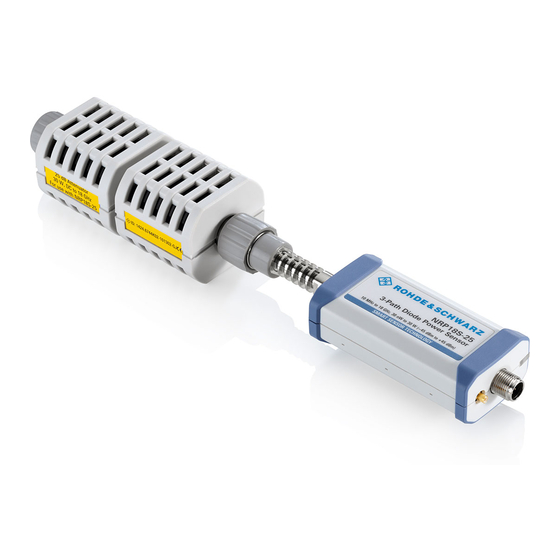
® Remote Control Commands R&S NRP18S-xx Configuring Basic Measurement Parameters Parameters: <duty_cycle> Range: 0.001 to 100.00 *RST: 1.00 Default unit: Percent [SENSe<Sensor>:]CORRection:DCYCle:STATe <state> Enables or disables the duty cycle correction for the measured value. Parameters: <state> *RST: 8.8.4.2 Offset Corrections The offset accounts for external losses by adding a fixed level offset in dB. - Page 88 ® Remote Control Commands R&S NRP18S-xx Configuring Basic Measurement Parameters attached to a power sensor. Using S-parameters instead of a fixed offset increases measurement accuracy by accounting for the interaction between the sensor and the component. It shifts the reference plane of the sensor from its RF connector to the input of the device that is being applied externally.
- Page 89 ® Remote Control Commands R&S NRP18S-xx Configuring Basic Measurement Parameters 3-Path Diode Power Sensor MHz to GHz, 100 pW to 200 mW (−70 dBm to +23 dBm) SMART SENSOR TECHNOLOGY Figure 8-7: Operation with 2-port device between signal source and sensor input Configuring the S-Parameter Correction ..............
-
Page 90: S-Gamma Corrections
® Remote Control Commands R&S NRP18S-xx Configuring Basic Measurement Parameters 8.8.4.4 S-Gamma Corrections Using the complex reflection coefficient, you can determine the power P delivered by the signal source with considerably greater accuracy. The coefficient of the signal source Γ is defined by its magnitude and phase: source ●... -
Page 91: Using The S-Parameters Tool
® Remote Control Commands R&S NRP18S-xx Configuring Basic Measurement Parameters [SENSe<Sensor>:]SGAMma:CORRection:STATe <state> Enables or disables the use of the complex reflection coefficient to correct the interac- tions of power sensor and signal source. Parameters: <state> *RST: [SENSe<Sensor>:]SGAMma:MAGNitude <magnitude> Sets the magnitude of the complex reflection coefficient of the source, Γ source Parameters: 0.0 ≙... -
Page 92: Menu Bar
® Remote Control Commands R&S NRP18S-xx Configuring Basic Measurement Parameters User Interface of the S-Parameters Tool Figure 8-10: S-Parameters dialog Menu bar........................92 └ File........................92 └ Sensor......................93 └ Device......................93 └ Options......................93 └ User Data....................93 └ Remote....................93 └ Show Cal. -
Page 93: Sensor
® Remote Control Commands R&S NRP18S-xx Configuring Basic Measurement Parameters Sensor ← Menu bar Provides options for loading and saving calibration data directly from or to the sensor, see: ● "To load a calibration data set from a power sensor" on page 95 ●... -
Page 94: Global Flags
® Remote Control Commands R&S NRP18S-xx Configuring Basic Measurement Parameters Figure 8-11: Example Global Flags Groups the settings for the power sensor behavior regarding S-parameter corrections. S-Parameter Correction ON by Default ← Global Flags If this option is enabled, the S-parameter correction is activated automatically when the sensor is started. -
Page 95: Use Flags In Factory Cal. Data Set
® Remote Control Commands R&S NRP18S-xx Configuring Basic Measurement Parameters Use Flags in Factory Cal. Data Set ← Global Flags Available if the power sensor supports two different calibration data sets: ● Factory calibration data set containing all factory calibration data. ●... - Page 96 ® Remote Control Commands R&S NRP18S-xx Configuring Basic Measurement Parameters The "Upload Calibration Data" dialog opens. It shows a list of the available sen- sors. 3. If you cannot find your power sensor in the list, for example because of reconnect- ing the power sensor, you can reload the list by clicking "Rebuild List".
- Page 97 ® Remote Control Commands R&S NRP18S-xx Configuring Basic Measurement Parameters 6. Create a backup of the calibration data set before making any changes. Select "File" > "Save Calibration Data". A dialog opens where you can select the location to save the calibration data. To change the S-parameter data 1.
- Page 98 ® Remote Control Commands R&S NRP18S-xx Configuring Basic Measurement Parameters 4. If needed, load uncertainty data. See "To load an uncertainty parameter file" on page 98. 5. Check the entries in the "S-Parameter Device Mnemonic", "Lower Power Limit/W" and "Upper Power Limit/W" fields and change them, if necessary. For example, the lower and upper power limits are deduced from the power limits of the sensor itself and the minimum attenuation of the S-parameter device.
- Page 99 ® Remote Control Commands R&S NRP18S-xx Configuring Basic Measurement Parameters To save the calibration data to the sensor 1. Select "Sensor" > "Save Calibration Data". The "Download Calibration Data" dialog opens. 2. Confirm that the correct power sensor is selected by clicking "Download". After a successful transfer of the data to the power sensor, a confirmation message is displayed.
- Page 100 ® Remote Control Commands R&S NRP18S-xx Configuring Basic Measurement Parameters ● Option line The option line has the format #[<frequency unit>][<parameter>][<format>][<R n>], where: – Identifies the option line. – <frequency unit> Possible values are Hz, kHz, MHz or GHz. If a frequency unit is not specified, GHz is implicitly assumed.
-
Page 101: Calibrating/Zeroing The Power Sensor
® Remote Control Commands R&S NRP18S-xx Calibrating/Zeroing the Power Sensor U must be specified for uncertainty data files. If a parameter is not specified, S is implicitly assumed and as a result an error message is triggered. – <format> This value is ignored in uncertainty measurement files. The entry is therefore irrelevant. - Page 102 ® Remote Control Commands R&S NRP18S-xx Calibrating/Zeroing the Power Sensor ......................102 CALibration:DATA .................... 102 CALibration:DATA:LENGth? ....................102 CALibration:USER:DATA .................. 102 CALibration:USER:DATA:LENGth? ................103 CALibration<Channel>:ZERO:AUTO CALibration:DATA <caldata> Writes a binary calibration data set in the memory of the sensor. Parameters: <caldata> <block_data>...
-
Page 103: Testing The Power Sensor
® Remote Control Commands R&S NRP18S-xx Testing the Power Sensor CALibration<Channel>:ZERO:AUTO <state> Performs zero calibration. Turn off all test signals before zeroing. An active test signal during zeroing causes an error. While zero calibration is in progress, no queries or other setting commands are allowed, since the command is synchronous. -
Page 104: Configuring The System
® Remote Control Commands R&S NRP18S-xx Configuring the System Query parameters: <Item> String Usage: Query only 8.11 Configuring the System The SYSTem subsystem contains a series of commands for general functions that do not directly affect the measurement. The SYSTem:COMMunicate:NETWork:... commands are only available for the R&S NRP LAN power sensors. -
Page 105: System:communicate:network:restart
® Remote Control Commands R&S NRP18S-xx Configuring the System ......................114 SYSTem:SERRor? ................... 114 SYSTem:SERRor:LIST:ALL? ..................114 SYSTem:SERRor:LIST[:NEXT]? ......................115 SYSTem:SUTime ......................115 SYSTem:TLEVels? ..................115 SYSTem:TRANsaction:BEGin .................... 115 SYSTem:TRANsaction:END ....................115 SYSTem[:SENSor]:NAME ......................116 SYSTem:VERSion? SYSTem:COMMunicate:NETWork:RESTart Effective only for the R&S NRP LAN power sensors. Restarts the network connection to the DUT, that means terminates the connection and sets it up again. -
Page 106: System:communicate:network[:Common]:Hostname
® Remote Control Commands R&S NRP18S-xx Configuring the System SYSTem:COMMunicate:NETWork[:COMMon]:HOSTname <hostname> Effective only for the R&S NRP LAN power sensors. Sets the individual hostname of the sensor. In a LAN that uses a DNS server (domain name system server), you can access each connected instrument using a unique hostname instead of its IP address. -
Page 107: System:communicate:network:ipaddress:info
® Remote Control Commands R&S NRP18S-xx Configuring the System Example: SYST:COMM:NETW:IPAD:GAT '192.168.10.254' Sets 192.168.10.254 as IP address of the default gateway. SYSTem:COMMunicate:NETWork:IPADdress:INFO? Effective only for the R&S NRP LAN power sensors. Queries the network status information. Usage: Query only SYSTem:COMMunicate:NETWork:IPADdress:MODE <mode> Effective only for the R&S NRP LAN power sensors. -
Page 108: System:error:all
® Remote Control Commands R&S NRP18S-xx Configuring the System SYSTem:ERRor:ALL? Queries all unread entries in the error/event queue and removes them from the queue. The response is a comma-separated list in first out order, each entry consisting of the error number and a short description of the error. Positive error numbers are instrument-dependent. -
Page 109: System:error[:Next]
® Remote Control Commands R&S NRP18S-xx Configuring the System SYSTem:ERRor[:NEXT]? Queries the error/event queue for the oldest entry and removes it from the queue. The response consists of an error number and a short description of the error. Positive error numbers are instrument-dependent. Negative error numbers are reserved by the SCPI standard. -
Page 110: System:help:headers
® Remote Control Commands R&S NRP18S-xx Configuring the System SYSTem:HELP:HEADers? [<Item>] Returns a list of all SCPI commands supported by the sensor. Query parameters: <Item> <block_data> Usage: Query only SYSTem:HELP:SYNTax? [<Item>] Queries the relevant parameter information for the specified SCPI command. Query parameters: <Item>... -
Page 111: System:initialize
® Remote Control Commands R&S NRP18S-xx Configuring the System Status Sensor Name Technology Function MinPower MaxPower MinFreq MaxFreq Resolution Impedance Coupling Uptime Cal. Misc. Cal. Abs. Cal. Refl. Cal. Temp. Cal. Lin. Cal. S-Para. Cal. S-Para. (User) SPD Mnemonic Cal. Due Date Certificate No Limit TestLimit... -
Page 112: System:led:color
® Remote Control Commands R&S NRP18S-xx Configuring the System Parameters: <language> SCPI *RST: SCPI SYSTem:LED:COLor <color> Sets the color and the flash code of the system status LED, if the operating mode of the LED is set to USER (SYSTem:LED:MODE). Parameters: <color>... -
Page 113: System:parameters
® Remote Control Commands R&S NRP18S-xx Configuring the System Use this query to determine a useful resolution for the result display near the lower measurement limit. Usage: Query only SYSTem:PARameters? Lists all commands with default values, limits and ranges. Usage: Query only SYSTem:PARameters:DELTa? Lists all commands that differ from the defined default status set by... - Page 114 ® Remote Control Commands R&S NRP18S-xx Configuring the System Parameters: <update_time> Range: 0.0 to 10.0 *RST: Default unit: Seconds SYSTem:SERRor? Queries the next static error, if available. Static errors are more severe than normal error conditions, which can be queried using SYSTem:ERRor[:NEXT]?. Normal errors result from, for example, unknown commands or syntax errors and gen- erally affect a single parameter or setting.
- Page 115 ® Remote Control Commands R&S NRP18S-xx Configuring the System Usage: Query only SYSTem:SUTime <update_time> Effective only in the NRP legacy mode. Sets the status update time. That is the maximum rate in which the power sensor can output measurement results. Relevant only in continuous measurement mode (INITiate:CONTinuousON).
-
Page 116: Using The Status Register
® Remote Control Commands R&S NRP18S-xx Using the Status Register Figure 8-12: Sensor Name Parameters: <sensorname> SYSTem:VERSion? Queries the SCPI version that the command set of the sensor complies with. Example: SYST:VERS? Query 1999.0 Response: SCPI version from 1999. Usage: Query only 8.12 Using the Status Register Further information:... - Page 117 ® Remote Control Commands R&S NRP18S-xx Using the Status Register STATus:QUEue[:NEXT]? Queries the most recent error queue entry and deletes it. Positive error numbers indicate sensor specific errors. Negative error numbers are error messages defined by SCPI. If the error queue is empty, the error number 0, "No error", is returned. Usage: Query only 8.12.2 Reading Out the CONDition Part...
- Page 118 ® Remote Control Commands R&S NRP18S-xx Using the Status Register 8.12.4 Controlling the ENABle Part Further information: ● Chapter 10.3.2, "Structure of a SCPI Status Register", on page 136 STATus:DEVice:ENABle <value> STATus:OPERation:CALibrating:ENABle <value> STATus:OPERation:ENABle <value> STATus:OPERation:LLFail:ENABle <value> STATus:OPERation:MEASuring:ENABle <value> STATus:OPERation:SENSe:ENABle <value> STATus:OPERation:TRIGger:ENABle <value>...
- Page 119 ® Remote Control Commands R&S NRP18S-xx Using the Status Register STATus:OPERation:PTRansition <value> STATus:OPERation:LLFail:PTRansition <value> STATus:OPERation:MEASuring:PTRansition <value> STATus:OPERation:SENSe:PTRansition <value> STATus:OPERation:TRIGger:PTRansition <value> STATus:OPERation:ULFail:PTRansition <value> STATus:QUEStionable:CALibration:PTRansition <value> STATus:QUEStionable:PTRansition <value> STATus:QUEStionable:POWer:PTRansition <value> STATus:QUEStionable:WINDow:PTRansition <value> Parameters: <value> *RST: 65535 User Manual 1178.3686.02 ─ 05...
-
Page 120: Performing Measurement Tasks - Programming Examples
® Performing Measurement Tasks - Programming Examples R&S NRP18S-xx Performing the Fastest Measurement in Continuous Average Mode 9 Performing Measurement Tasks - Program- ming Examples If you install the optional software development kit (SDK) of the R&S NRP Toolkit, pro- gramming examples are provided. - Page 121 ® Performing Measurement Tasks - Programming Examples R&S NRP18S-xx Performing the Fastest Measurement in Continuous Average Mode write( '*RST' ) # Enable fast unchopped continuous average measurement write( 'SENS:POW:AVG:FAST ON' ) # Define output format (float) write( 'FORM:DATA REAL,32' ) # Select the trigger condition.
- Page 122 ® Performing Measurement Tasks - Programming Examples R&S NRP18S-xx Performing the Fastest Measurement in Continuous Average Mode 9.2.2 Triggered Fast Unchopped Continuous Average Measurement This example, written in pseudo code, shows how to set up and execute a fast unchop- ped continuous average measurement.
-
Page 123: Performing A Buffered Continuous Average Measurement
® Performing Measurement Tasks - Programming Examples R&S NRP18S-xx Performing a Buffered Continuous Average Measurement # If there is any result in the buffer --> read it if ( query( 'BUFF:COUN?') > 0 ) result = queryBinary( 'BUFF:DATA?' ) numData = numData + result.size # Stop the continuous measurement utilDeviceIO.DeviceWrite( instrument, 'INIT:CONT OFF' ) 9.3 Performing a Buffered Continuous Average Measure-... - Page 124 ® Performing Measurement Tasks - Programming Examples R&S NRP18S-xx Performing a Buffered Continuous Average Measurement // Buffer size is randomly selected to 17 SENSOR.write( "SENS:BUFF:SIZE 17" ); SENSOR.write( "SENS:BUFF:STAT ON" ); SENSOR.write( "TRIG:COUN 17" ); // Read out all errors / Clear error queue SENSOR.query( "SYST:ERR:ALL?", szBuf, sizeof( szBuf ) );...
-
Page 125: Performing Trace Measurements
® Performing Measurement Tasks - Programming Examples R&S NRP18S-xx Performing Trace Measurements 9.4 Performing Trace Measurements *RST //Set the sensor's operation mode to trace SENSe:FUNCtion "XTIMe:POWer" //Set the carrier frequency SENSe:FREQuency 1.8e9 //Set the number of points for the trace measurement //Using 500 points usually represents a good compromise //between USB transfer speed and resolution SENSe:TRACe:POINTs 500... -
Page 126: Trace Measurement With Synchronization To Measurement Complete
® Performing Measurement Tasks - Programming Examples R&S NRP18S-xx Trace Measurement with Synchronization to Measurement Complete 9.5 Trace Measurement with Synchronization to Measure- ment Complete This example, written in pseudo code, shows how to set up and execute a trace mea- surement using a non-blocking technique. - Page 127 ® Performing Measurement Tasks - Programming Examples R&S NRP18S-xx Trace Measurement with Synchronization to Measurement Complete // (this loop could also check for cancel-requests from the user or other break conditions) while ( ! bMeasReady ) query( "STAT:OPER:MEAS:EVEN?", &iEvent ); bMeasReady = ((iEvent &...
-
Page 128: Remote Control Basics
® Remote Control Basics R&S NRP18S-xx Remote Control Interfaces and Protocols 10 Remote Control Basics ● Remote Control Interfaces and Protocols............. 128 ● SCPI Command Structure..................129 ● Status Reporting System..................135 10.1 Remote Control Interfaces and Protocols For remote control, communication between the R&S NRP18S-xx power sensors and the controlling host is established based on various interfaces and protocols. -
Page 129: Scpi Command Structure
® Remote Control Basics R&S NRP18S-xx SCPI Command Structure USB Resource String The syntax of the used USB resource string is: USB::<vendor ID>::<product ID>::<serial number>[::INSTR] where: ● <vendor ID> is the vendor ID for Rohde & Schwarz (0x0AAD) ● <product ID> is the product ID for the Rohde & Schwarz sensor ●... - Page 130 ® Remote Control Basics R&S NRP18S-xx SCPI Command Structure *RST RESET Resets the instrument. *ESE EVENT STATUS ENABLE Sets the bits of the event status enable registers. *ESR? EVENT STATUS QUERY Queries the contents of the event status register. *IDN? IDENTIFICATION QUERY Queries the instrument identification string.
- Page 131 ® Remote Control Basics R&S NRP18S-xx SCPI Command Structure Example: Definition: INITiate[:IMMediate] Command: INIT:IMM is equivalent to INIT Parameters Parameters must be separated from the header by a "white space". If several parame- ters are specified in a command, they are separated by a comma. For a description of the parameter types, refer to Chapter 10.2.3, "SCPI Parameters",...
- Page 132 ® Remote Control Basics R&S NRP18S-xx SCPI Command Structure Units For physical quantities, you can enter the unit. Only basic units are allowed and recog- nized, see Table 10-3. If you omit the unit, the basic unit is used. Table 10-3: Units Noted default unit Corresponding basic unit Frequency...
- Page 133 ® Remote Control Basics R&S NRP18S-xx SCPI Command Structure Example: Setting command: SENSe:AVERage:COUNt:AUTO ON Query: SENSe:AVERage:COUNt:AUTO? Response: 1 Text parameters Text parameters observe the syntactic rules for mnemonics, i.e. they can be entered using a short or long form. Like any parameter, they have to be separated from the header by a white space.
- Page 134 ® Remote Control Basics R&S NRP18S-xx SCPI Command Structure 10.2.4 Overview of Syntax Elements The following table provides an overview of the syntax elements: The colon separates the mnemonics of a command. In a command line, the separating semico- lon marks the uppermost command level. The semicolon separates two commands of a command line.
-
Page 135: Status Reporting System
® Remote Control Basics R&S NRP18S-xx Status Reporting System A new command line always begins with the complete path. Example: TRIG:LEV 0.1E-3 TRIG:DEL 3E-3 10.2.6 Responses to Queries A query is defined for each setting command unless explicitly specified otherwise. It is formed by adding a question mark to the associated setting command. - Page 136 ® Remote Control Basics R&S NRP18S-xx Status Reporting System Output queue Error/event queue Service request enable Status byte & Device status & & & Questionable status & & Standard event status RQS/MSS Operation status & Service request to controller at transition from 0 to 1 Figure 10-1: Status registers overview Chapter 10.3.3, "Status Byte (STB) and Service Request Enable Register...
- Page 137 ® Remote Control Basics R&S NRP18S-xx Status Reporting System significant bit, is set to 0 in all registers, thus preventing problems some controllers have with the processing of unsigned integers. Figure 10-2: Standard SCPI status register CONDition status register part The five parts of a SCPI register have different properties and functions: The CONDition part is written into directly by the hardware or the sum bit of the next lower register.
- Page 138 ® Remote Control Basics R&S NRP18S-xx Status Reporting System EVENt status register part The EVENt part indicates whether an event has occurred since the last reading, it is the "memory" of the condition part. It only indicates events passed on by the transition filters.
- Page 139 ® Remote Control Basics R&S NRP18S-xx Status Reporting System Table 10-4: Used status byte bits and their meaning Short description Bit is set if Device status register summary A sensor is connected or disconnected or when an error has occurred in a sensor, depending on the configuration of the sensor status register.
- Page 140 ® Remote Control Basics R&S NRP18S-xx Status Reporting System 10.3.5 Device Status Register Sensor error summary Sensor error Sensor error Sensor error Sensor error Legacy locked Reference PLL locked Figure 10-3: Device status register Querying the register: ● STATus:DEVice:CONDition? ● STATus:DEVice[:EVENt]? Querying the static errors: ●...
- Page 141 ® Remote Control Basics R&S NRP18S-xx Status Reporting System Bit no. Short description Bit is set if Legacy locked state The power sensor is locked in the NRP legacy mode. Via the SCPI channels (USBTMC or TCP/IP), only query commands can be sent, but no setting commands.
- Page 142 ® Remote Control Basics R&S NRP18S-xx Status Reporting System Power summary Calibration summary POST failure Figure 10-4: Questionable status register Querying the register: ● STATus:QUEStionable:CONDition? ● STATus:QUEStionable[:EVENt]? Table 10-6: Used questionable status bits and their meaning Bit no. Short description Bit is set if Power summary Summary of...
- Page 143 ® Remote Control Basics R&S NRP18S-xx Status Reporting System Sensor power Sensor please zero Figure 10-5: Questionable power status register Querying the register: ● STATus:QUEStionable:POWer:CONDition? ● STATus:QUEStionable:POWer[:SUMMary][:EVENt]? Table 10-7: Used questionable power status bits and their meaning Bit no. Short description Bit is set if Sensor power Measurement data of the power sensor is corrupt.
- Page 144 ® Remote Control Basics R&S NRP18S-xx Status Reporting System Sensor calibration Figure 10-6: Questionable calibration status register Querying the register: ● STATus:QUEStionable:CALibration:CONDition? ● STATus:QUEStionable:CALibration[:SUMMary][:EVENt]? Table 10-8: Used questionable calibration status bits and their meaning Bit no. Short description Bit is set if Sensor calibration Zeroing of the power sensor was not successful.
- Page 145 ® Remote Control Basics R&S NRP18S-xx Status Reporting System Operation Complete Query Error Device-Dependent Error Execution Error Command Error User Request Power On Figure 10-7: Standard event status register (ESR) Table 10-9: Used standard event status bits and their meaning Bit no.
- Page 146 ® Remote Control Basics R&S NRP18S-xx Status Reporting System Calibrating Measuring Triggering Sense summary Lower limit fail Upper limit fail Figure 10-8: Operation status register Querying the register: ● STATus:OPERation:CONDition? ● STATus:OPERation[:EVENt]? Table 10-10: Used operation status bits and their meaning Bit no.
- Page 147 ® Remote Control Basics R&S NRP18S-xx Status Reporting System Sensor calibrating Figure 10-9: Operation calibrating status register Querying the register: ● STATus:OPERation:CALibrating:CONDition? ● STATus:OPERation:CALibrating[:SUMMary][:EVENt]? Table 10-11: Used operation calibrating status bits and their meaning Bit no. Short description Bit is set if Sensor calibrating Sensor is being calibrated.
- Page 148 ® Remote Control Basics R&S NRP18S-xx Status Reporting System Sensor measuring Figure 10-10: Operation measuring status register Querying the register: ● STATus:OPERation:MEASuring:CONDition? ● STATus:OPERation:MEASuring[:SUMMary][:EVENt]? Table 10-12: Used operation measuring status bits and their meaning Bit no. Short description Bit is set if Sensor measuring Sensor is measuring.
- Page 149 ® Remote Control Basics R&S NRP18S-xx Status Reporting System Sensor waiting for trigger Figure 10-11: Operation trigger status register Querying the register: ● STATus:OPERation:TRIGger:CONDition? ● STATus:OPERation:TRIGger[:SUMMary][:EVENt]? Table 10-13: Used operation trigger status bits and their meaning Bit no. Short description Bit is set if Sensor waiting for trigger Sensor is waiting for a trigger event.
- Page 150 ® Remote Control Basics R&S NRP18S-xx Status Reporting System Sensor initializing Figure 10-12: Operation sense status register Querying the register: ● STATus:OPERation:SENSe:CONDition? ● STATus:OPERation:SENSe[:SUMMary][:EVENt]? Table 10-14: Used operation sense status bits and their meaning Bit no. Short description Bit is set if Sensor initializing Sensor is being initialized.
- Page 151 ® Remote Control Basics R&S NRP18S-xx Status Reporting System Lower limit fail Figure 10-13: Operation lower limit fail status registers Querying the register: ● STATus:OPERation:LLFail:CONDition? ● STATus:OPERation:LLFail[:SUMMary][:EVENt]? Table 10-15: Used operation lower limit fail status bits and their meaning Bit no. Short description Bit is set if Lower limit fail...
- Page 152 ® Remote Control Basics R&S NRP18S-xx Status Reporting System Upper limit fail Figure 10-14: Operation upper limit fail status registers Querying the register: ● STATus:OPERation:ULFail:CONDition? ● STATus:OPERation:ULFail[:SUMMary][:EVENt]? Table 10-16: Used operation upper limit fail status bits and their meaning Bit no. Short description Bit is set if Upper limit fail...
-
Page 153: Troubleshooting
® Troubleshooting R&S NRP18S-xx Problems during a Firmware Update 11 Troubleshooting ● Displaying Status Information................153 ● Performing a Selftest.....................153 ● Problems during a Firmware Update..............153 ● Contacting Customer Support................154 11.1 Displaying Status Information Status information is available in several ways. Status LED of the R&S NRP18S-xx The position of the status LED is indicated in Chapter 4, "Power Sensor... -
Page 154: Contacting Customer Support
® Troubleshooting R&S NRP18S-xx Contacting Customer Support Firmware update was interrupted If, for example, a power cut happened during the firmware update, problems can occur. 1. Perform the firmware update again. Sometimes, a further update fixes the prob- lems. 2. If the power sensor is not accessible any more, contact the service. Firmware update was aborted If there is not enough free storage space, the firmware update is aborted. -
Page 155: List Of Commands
® List of Commands R&S NRP18S-xx List of Commands [SENSe<Sensor>:][POWer:][AVG:]APERture....................70 [SENSe<Sensor>:][POWer:][AVG:]BUFFer:CLEar..................71 [SENSe<Sensor>:][POWer:][AVG:]BUFFer:COUNt?..................71 [SENSe<Sensor>:][POWer:][AVG:]BUFFer:DATA?..................71 [SENSe<Sensor>:][POWer:][AVG:]BUFFer:SIZE....................71 [SENSe<Sensor>:][POWer:][AVG:]BUFFer:STATe..................71 [SENSe<Sensor>:][POWer:][AVG:]FAST......................72 [SENSe<Sensor>:][POWer:][AVG:]SMOothing:STATe..................72 [SENSe<Sensor>:][POWer:]BURSt:DTOLerance................... 73 [SENSe<Sensor>:][POWer:]BURSt:LENGth?....................74 [SENSe<Sensor>:][POWer:]TSLot[:AVG]:COUNt................... 75 [SENSe<Sensor>:][POWer:]TSLot[:AVG]:WIDTh....................75 [SENSe<Sensor>:][POWer:]TSLot[:AVG][:EXCLude]:MID:OFFSet[:TIME].............75 [SENSe<Sensor>:][POWer:]TSLot[:AVG][:EXCLude]:MID:TIME..............75 [SENSe<Sensor>:][POWer:]TSLot[:AVG][:EXCLude]:MID[:STATe]..............76 [SENSe<Sensor>:]AUXiliary..........................68 [SENSe<Sensor>:]AVERage:COUNt......................81 [SENSe<Sensor>:]AVERage:COUNt:AUTO....................82 [SENSe<Sensor>:]AVERage:COUNt:AUTO:MTIMe..................82 [SENSe<Sensor>:]AVERage:COUNt:AUTO:NSRatio..................82 [SENSe<Sensor>:]AVERage:COUNt:AUTO:RESolution................ - Page 156 ® List of Commands R&S NRP18S-xx [SENSe<Sensor>:]TRACe:DATA?........................77 [SENSe<Sensor>:]TRACe:MPWidth?......................80 [SENSe<Sensor>:]TRACe:OFFSet:TIME......................80 [SENSe<Sensor>:]TRACe:POINts........................80 [SENSe<Sensor>:]TRACe:REALtime......................80 [SENSe<Sensor>:]TRACe:TIME........................81 *CLS.................................43 *ESE................................44 *ESR?................................44 *IDN?................................44 *IST?................................44 *OPC................................44 *OPT?................................45 *PRE................................45 *RCL................................45 *RST................................45 *SAV.................................45 *SRE................................46 *STB?................................46 *TRG................................46 *TST?................................46 *WAI.................................47 ABORt................................49 CALCulate:FEED.............................67 CALibration:DATA............................
- Page 157 ® List of Commands R&S NRP18S-xx STATus:OPERation:ENABle.......................... 118 STATus:OPERation:LLFail:CONDition?......................117 STATus:OPERation:LLFail:ENABle....................... 118 STATus:OPERation:LLFail:NTRansition......................118 STATus:OPERation:LLFail:PTRansition......................119 STATus:OPERation:LLFail[:SUMMary][:EVENt]?..................117 STATus:OPERation:MEASuring:CONDition?....................117 STATus:OPERation:MEASuring:ENABle....................... 118 STATus:OPERation:MEASuring:NTRansition....................118 STATus:OPERation:MEASuring:PTRansition....................119 STATus:OPERation:MEASuring[:SUMMary][:EVENt]?..................117 STATus:OPERation:NTRansition........................118 STATus:OPERation:PTRansition........................119 STATus:OPERation:SENSe:CONDition?.......................117 STATus:OPERation:SENSe:ENABle......................118 STATus:OPERation:SENSe:NTRansition...................... 118 STATus:OPERation:SENSe:PTRansition...................... 119 STATus:OPERation:SENSe[:SUMMary][:EVENt]?..................117 STATus:OPERation:TRIGger:CONDition?.....................117 STATus:OPERation:TRIGger:ENABle......................118 STATus:OPERation:TRIGger:NTRansition....................
- Page 158 ® List of Commands R&S NRP18S-xx STATus:QUEue[:NEXT]?..........................117 SYSTem:COMMunicate:NETWork:IPADdress....................106 SYSTem:COMMunicate:NETWork:IPADdress:GATeway................106 SYSTem:COMMunicate:NETWork:IPADdress:INFO?...................107 SYSTem:COMMunicate:NETWork:IPADdress:MODE...................107 SYSTem:COMMunicate:NETWork:IPADdress:SUBNet:MASK..............107 SYSTem:COMMunicate:NETWork:RESet..................... 105 SYSTem:COMMunicate:NETWork:RESTart....................105 SYSTem:COMMunicate:NETWork:STATus?....................105 SYSTem:COMMunicate:NETWork[:COMMon]:DOMain................105 SYSTem:COMMunicate:NETWork[:COMMon]:HOSTname................106 SYSTem:DFPRint<Channel>?........................107 SYSTem:ERRor:ALL?............................108 SYSTem:ERRor:CODE:ALL?........................108 SYSTem:ERRor:CODE[:NEXT]?........................108 SYSTem:ERRor:COUNt?..........................108 SYSTem:ERRor[:NEXT]?..........................109 SYSTem:FWUPdate............................109 SYSTem:FWUPdate:STATus?........................109 SYSTem:HELP:HEADers?..........................110 SYSTem:HELP:SYNTax:ALL?........................110 SYSTem:HELP:SYNTax?..........................110 SYSTem:INFO?..............................110 SYSTem:INITialize............................111...
- Page 159 ® List of Commands R&S NRP18S-xx TRIGger:DTIMe............................... 60 TRIGger:EXTernal<2...2>:IMPedance......................60 TRIGger:HOLDoff............................61 TRIGger:HYSTeresis............................61 TRIGger:IMMediate............................61 TRIGger:LEVel..............................61 TRIGger:LEVel:UNIT............................62 TRIGger:MASTer:PORT..........................62 TRIGger:MASTer:STATe..........................62 TRIGger:SLOPe...............................63 TRIGger:SOURce............................63 TRIGger:SYNC:PORT............................. 63 TRIGger:SYNC:STATe.............................63 UNIT:POWer..............................64 User Manual 1178.3686.02 ─ 05...
-
Page 160: Index
® Index R&S NRP18S-xx Index ESE ................. 144 ESR ................. 144 Android device EVENt ................138 R&S Power Viewer Mobile .......... 29 Application cards ..............6 Application notes ..............6 Firmware update ............20, 35 Potential risks ............. 35 Problems ..............153 Basic measurement parameters Remote control ............ - Page 161 ® Index R&S NRP18S-xx Operation lower limit fail status register ......150 Service request enable register ........138 Operation measuring status register ....... 147 Sources Operation sense status register ........149 Trigger .................51 Operation status register ..........145 Special characters Operation trigger status register ........
- Page 162 ® Index R&S NRP18S-xx USB sensor hub ..............13 User manual ................ 5 Versions of R&S NRP software ......... 20 White papers ............... 6 User Manual 1178.3686.02 ─ 05...
Need help?
Do you have a question about the NRP18S Series and is the answer not in the manual?
Questions and answers