R&S NRQ6 Getting Started
Frequency selective power sensor
Hide thumbs
Also See for NRQ6:
- Getting started (61 pages) ,
- Getting started (59 pages) ,
- User manual (246 pages)

Subscribe to Our Youtube Channel
Related Manuals for R&S NRQ6


Summary of Contents for R&S NRQ6
- Page 1 ® R&S NRQ6 Frequency Selective Power Sensor Getting Started (;ÜU52) 1178370502 Version 08...
- Page 2 Rohde & Schwarz GmbH & Co. KG. Trade names are trademarks of the owners. ® 1178.3705.02 | Version 08 | R&S NRQ6 ® Throughout this manual, products from Rohde & Schwarz are indicated without the symbol , e.g. ® R&S NRQ6 is indicated as R&S NRQ6.
-
Page 3: Table Of Contents
® Contents R&S NRQ6 Contents 1 Safety and regulatory information........7 1.1 Safety instructions................7 1.2 Labels on the product................9 1.3 Warning messages in the documentation.......... 9 2 Welcome................11 2.1 Documentation overview..............11 2.1.1 Getting started manual................11 2.1.2 User manual..................11 2.1.3 CD-ROM....................11... - Page 4 Contents R&S NRQ6 3.6.2 Computer using a USB connection............25 3.6.3 R&S NRX base unit................28 4 R&S NRQ6 tour..............31 4.1 RF connector..................31 4.2 Status information................32 4.3 LAN PoE+ interface................32 4.4 Host interface..................34 4.5 Trigger 2 I/O (TRIG2)................35 4.6 Reference I/O (REF)................
- Page 5 ® Contents R&S NRQ6 6.2 Ethernet interface................51 6.2.1 VISA resource strings................51 7 Contacting customer support..........55 Index..................57 Getting Started 1178.3705.02 ─ 08...
- Page 6 ® Contents R&S NRQ6 Getting Started 1178.3705.02 ─ 08...
-
Page 7: Safety And Regulatory Information
Intended use The R&S NRQ6 is intended for precise and fast power measurements in develop- ment and for monitoring and maintenance purposes. The supported base units are listed in the data sheet. Observe the operating conditions and performance limits stated in the data sheet. - Page 8 ® Safety and regulatory information R&S NRQ6 Safety instructions Use the product only for its intended use and within its performance limits. Inten- ded use and limits are described in the product documentation such as the data sheet, manuals and the printed "Safety Instructions". If you are unsure about the appropriate use, contact Rohde &...
-
Page 9: Labels On The Product
® Safety and regulatory information R&S NRQ6 Warning messages in the documentation Labels on the product Labels on the product inform about: ● Personal safety "Meaning of safety labels" on page 8. ● Environment safety Table 1-1. ● Identification of the product "Default hostname"... - Page 10 ® Safety and regulatory information R&S NRQ6 Warning messages in the documentation Getting Started 1178.3705.02 ─ 08...
-
Page 11: Welcome
2.1.1 Getting started manual Introduces the R&S NRQ6 and describes how to set up and start working with the product. A printed version is delivered with the R&S NRQ6. 2.1.2 User manual Contains the description of all instrument modes and functions. It also provides... -
Page 12: Application Sheets
Tutorials offer guided examples and demonstrations on operating the R&S NRQ6. They are provided on the product page of the internet. 2.1.6 Instrument security procedures Deals with security issues when working with the R&S NRQ6 in secure areas. It is available for download on the Internet. 2.1.7 Basic safety instructions Contains safety instructions, operating conditions and further important informa- tion. -
Page 13: 2.1.10 Application Notes, Application Cards, White Papers, Etc
Key features The R&S NRQ6 frequency selective power sensor sets standards in RF perfor- mance and usability. Outstanding key features are: ● Combines the advantages of a measurement receiver (dynamic range, linear- ity & video bandwidth) and a conventional diode-based or thermal power sen- sor (stability, absolute accuracy &... - Page 14 ® Welcome R&S NRQ6 Key features Getting Started 1178.3705.02 ─ 08...
-
Page 15: Preparing For Use
® Preparing for use R&S NRQ6 Choosing the operating site Preparing for use Here, you can find basic information about setting up the product for the first time. ● Unpacking and checking................. 15 ● Choosing the operating site................15 ●... -
Page 16: Considerations For Test Setup
Allow sufficient airflow The R&S NRQ6 has fan openings at both sides of the casing, as shown in Fig- 4-1. If the R&S NRQ6 runs with insufficient airflow for a longer period, the R&S NRQ6 overheats. -
Page 17: Connecting To A Dut
● Airflow perforations are unimpeded. ● Minimum distance between the fan openings and any object is 10 cm. Connecting to a DUT For connecting the R&S NRQ6 to a DUT, use the RF connector of the R&S NRQ6. For details, see Chapter 4.1, "RF connector",... -
Page 18: Connecting To A Power Supply
Carefully loosen the union nut at the front of the RF connector of the R&S NRQ6. 2. Remove the R&S NRQ6. Connecting to a power supply The power for the R&S NRQ6 is supplied over the LAN PoE+ interface. See also Chapter 4.3, "LAN PoE+ interface", on page 32. -
Page 19: Computer Using A Lan Connection
R&S NRX base unit..................28 3.6.1 Computer using a LAN connection There are different ways to connect the R&S NRQ6 to a computer according to the available equipment. The power for the R&S NRQ6 is supplied over the LAN PoE+ interface. Further information: ●... - Page 20 = RJ.45 Ethernet connector 4, 6 = RJ.45 Ethernet cable = Computer = Ethernet switch supporting PoE+ power delivery 1. Connect the [RF] connector of the R&S NRQ6 to the DUT. See Chapter 3.4, "Connecting to a DUT", on page 17.
- Page 21 "Connecting to a DUT", on page 17. 2. Connect the RJ.45 Ethernet connector of the R&S NRQ6 to the output of the PoE+ injector. 3. Connect the PoE+ injector to a power supply. 4. Connect the input of the PoE+ injector to the non-PoE+ Ethernet switch.
- Page 22 "Connecting to a DUT", on page 17. 2. Connect the RJ.45 Ethernet connector of the R&S NRQ6 to the output of the PoE+ injector. 3. Connect the PoE+ injector to a power supply. 4. Connect the computer to the input of the PoE+ injector.
- Page 23 By default, the R&S NRQ6 is configured to use dynamic TCP/IP configuration (DHCP) and to obtain the address information automatically. If both LAN status LEDs are illuminated in green color, the R&S NRQ6 is cor- rectly connected to the network.
- Page 24 ● If the network does not support DHCP, the R&S NRQ6 tries to obtain the IP address via the Zeroconf (APIPA = automatic private IP addressing) protocol. If this attempt does not succeed or if the R&S NRQ6 is set to use an alternate TCP/IP configuration, you have to set the IP address manually.
-
Page 25: Computer Using A Usb Connection
R&S NRQ6 by the same identification, irrespective of whether it is a network or a point-to-point connection. 3.6.2 Computer using a USB connection You can connect an R&S NRQ6 to a computer using the host interface and con- trol it as described in Chapter 5, "Operating concepts", on page 37. - Page 26 5 = USB connector 6 = Computer with installed VISA driver or R&S NRP Toolkit 7 = PoE+ injector 8 = AC supply 1. Connect the R&S NRQ6 to the signal source (DUT). See Chapter 3.4, "Con- necting to a DUT", on page 17.
- Page 27 The R&S NRP‑Z5 sensor hub (high-speed USB 2.0) can host up to four R&S NRQ6 power sensors and provides simultaneous external triggering to all con- nected sensors. It comes with an external power supply unit, a power cable and a USB cable.
-
Page 28: R&S Nrx Base Unit
3.6.3 R&S NRX base unit You can use an R&S NRX base unit as controlling host. Connect the R&S NRQ6 to the R&S NRX using the host interface. The R&S NRX supports the configura- tion of 2 directly connected R&S NRQ6, if enhanced accordingly. For details, see the user manual and the data sheet of the R&S NRX. - Page 29 Insert this connector into one of the sensor ports of the R&S NRX. ► If you want to disconnect the cable from the host interface of the R&S NRQ6: a) Loosen the union nut of the screw-lock cable connector.
- Page 30 ® Preparing for use R&S NRQ6 Connecting to a controlling host Getting Started 1178.3705.02 ─ 08...
-
Page 31: S Nrq6 Tour
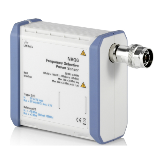
NRQ6 RF connector R&S NRQ6 tour This chapter provides an overview of the available connectors and LEDs of the R&S NRQ6. Figure 4-1: R&S NRQ6 frequency selective power sensor = RF connector, see Chapter 4.1, "RF connector", on page 31 2, 10 = Fan openings, see Chapter 4.9, "Fan... -
Page 32: Status Information
® R&S NRQ6 tour R&S NRQ6 LAN PoE+ interface The male N connector is used to connect the R&S NRQ6 to the device under test (DUT) or a signal generator, see Chapter 3.4, "Connecting to a DUT", on page 17. - Page 33 5 cables or better. The power for the R&S NRQ6 is supplied over the LAN PoE+ interface. The LAN PoE+ interface also connects the R&S NRQ6 to a local area network (LAN) for remote control, remote operation and data transfer.
-
Page 34: Host Interface
Host interface See (4) in Figure 4-1. The 8-pole male sensor connector (M12) is used to connect the R&S NRQ6 to a computer or an R&S NRX base unit. Further information: ● Chapter 3.6.1, "Computer using a LAN connection",... -
Page 35: Trigger 2 I/O (Trig2)
The female SMA connector is used as an input or output for the reference clock. By default, the R&S NRQ6 generates a 10 MHz reference signal and uses it as reference clock. You can use this signal as a reference clock for other devices (output). -
Page 36: Local Oscillator I/O (Lo)
See (9, 10) in Figure 4-1. The R&S NRQ6 has fan openings on the top and on the bottom of the casing. When connecting the R&S NRQ6, be careful to allow sufficient airflow as speci- fied in "Allow sufficient airflow"... -
Page 37: Operating Concepts
Chapter 5.4, "Remote control", on page 46 Also, the R&S NRQ6 is supported by the R&S Power Viewer. The R&S Power Viewer is provided on your documentation CD-ROM and on the Rohde & Schwarz website as a separate standalone installation package. -
Page 38: System Requirements
® Operating concepts R&S NRQ6 R&S NRP Toolkit 5.1.2 System requirements Hardware requirements: ● Desktop computer or laptop, or an Intel-based Apple Mac ● LAN interface and equipment for setting up a LAN connection. Chapter 3.6.1, "Computer using a LAN connection",... -
Page 39: Browser-Based User Interface
For further details, refer to the user manual. Browser-based user interface With the integrated, browser-based graphical user interface of the R&S NRQ6, you can easily configure the settings and measure in the provided measurement modes. Open a web browser on your controlling host and connect to the R&S NRQ6. - Page 40 DUT", on page 17. To display the Web user interface 1. Open a supported web browser. 2. Enter the hostname of the R&S NRQ6 you want to connect to. See Chap- ter 3.6.1.5, "Using hostnames", on page 23.
-
Page 41: Layout Of The Main Dialog
Displays the status of the R&S NRQ6. The colors are explained in Chapter 4.2, "Status information", on page 32. You can also display detailed information. If the R&S NRQ6 is in remote mode, the status is displayed next to the status LED, see Figure 5-2. Getting Started 1178.3705.02 ─ 08... -
Page 42: Tooltips
® Operating concepts R&S NRQ6 Browser-based user interface Sensor information (3) in Figure 5-1 Serial number of the R&S NRQ6 and installed firmware version Top pane (4) in Figure 5-1 Stays always visible. Navigation pane (5) in Figure 5-1 For displaying measurement and system settings in the settings pane. -
Page 43: Toolbar In Charts
® Operating concepts R&S NRQ6 Browser-based user interface 5.2.3 Toolbar in charts If you move the mouse into a chart, a toolbar becomes visible in the upper right corner. Use the toolbar to analyze the chart in detail. Table 5-1: Icons for chart analysis... - Page 44 ® Operating concepts R&S NRQ6 Browser-based user interface Table 5-2: Short forms of units Quantity Short Corresponding forms * unit Frequency Time μs * Both capital and small letters are accepted. ► If you want to change a number, you can also: ●...
-
Page 45: R&S Nrx
® Operating concepts R&S NRQ6 R&S NRX To toggle between two possible values If only two values are possible, you can toggle between these values. Toggling works for the pairs "Off"/"On", "Auto"/"Manual", "Left"/"Right", etc. ► Click the value to change to the other value. -
Page 46: Remote Control
For a detailed description of how to measure in this setup, refer to the user man- ual of the R&S NRX. Remote control You can remote control the R&S NRQ6 easily. The change to remote control occurs "on the fly". Switching to remote control 1. - Page 47 ® Operating concepts R&S NRQ6 Remote control The R&S NRQ6 changes into local mode. The lock of the web user interface is removed. Further information: ● See the user manual for details. ● Chapter 6, "Remote control interfaces and protocols", on page 49 ●...
- Page 48 ® Operating concepts R&S NRQ6 Remote control Getting Started 1178.3705.02 ─ 08...
-
Page 49: Remote Control Interfaces And Protocols
Remote control interfaces and protocols R&S NRQ6 USB interface Remote control interfaces and protocols For remote control, communication between the R&S NRQ6 and the controlling host is established based on the following interfaces and protocols. Table 6-1: Supported interfaces and protocols Interface Protocol Library... - Page 50 It defines a dedicated class code that identifies a device's functionality. R&S NRQ6 also uses this class code to identify itself as a member of the test & measurement class. Using a VISA library, such devices support service request, trigger and other operations that are commonly found in GPIB devices.
-
Page 51: Ethernet Interface
Remote control interfaces and protocols R&S NRQ6 Ethernet interface Ethernet interface The Ethernet interface of the R&S NRQ6 allows you to integrate it in a local area network (LAN). Requirements ● TCP/IP network protocol The local area network must support the TCP/IP network protocol. - Page 52 ® Remote control interfaces and protocols R&S NRQ6 Ethernet interface The IP address or hostname is used by the programs to identify and control the sensor. While the hostname is determined by settings in the sensor, the IP address is assigned by a DHCP server when the sensor requests one. Alterna- tively the IP address is determined with a procedure called Zeroconf.
- Page 53 A power sensor has the IP address 10.111.11.20; the valid resource string using VXI-11 protocol is: TCPIP::10.111.11.20::INSTR The DNS host name is nrq6-100001; the valid resource string is: TCPIP::nrq6-100001::hislip0 (HiSLIP) TCPIP::nrq6-100001::inst0 (VXI-11) A raw socket connection can be established using: TCPIP::10.111.11.20::5025::SOCKET...
- Page 54 ® Remote control interfaces and protocols R&S NRQ6 Ethernet interface Getting Started 1178.3705.02 ─ 08...
-
Page 55: Contacting Customer Support
® Contacting customer support R&S NRQ6 Contacting customer support Technical support – where and when you need it For quick, expert help with any Rohde & Schwarz product, contact our customer support center. A team of highly qualified engineers provides support and works with you to find a solution to your query on any aspect of the operation, program- ming or applications of Rohde &... - Page 56 ® Contacting customer support R&S NRQ6 Getting Started 1178.3705.02 ─ 08...
-
Page 57: Index
® Index R&S NRQ6 Index Disconnecting DUT ............ 17 Application cards ........13 R&S NRX ..........29 Application notes ........13 USB host ..........27 Application sheets ........12 Download R&S NRP Toolkit .........37 Brochures ..........12 Connecting ..........17 Browser-based user interface ....39 Disconnecting ........ - Page 58 ® Index R&S NRQ6 Non-PoE+ Ethernet switch ....21 System requirements ......38 PoE+ Ethernet switch ......20 Versions ..........37 PoE+ injector ........ 21, 22 R&S NRP‑Z5 ........... 27 Setup ..........22 R&S NRX ..........45 LAN connector .........32 Connecting ........18, 29...
- Page 59 ® Index R&S NRQ6 Unpacking ..........15 USB connection Simple ..........26 USB sensor hub ........27 USB interface Remote control ........49 USB resource string ........ 50 USB sensor hub ........27 USBTMC protocol ........50 User manual ..........11 VISA Resource string ........51...
Need help?
Do you have a question about the NRQ6 and is the answer not in the manual?
Questions and answers