
Related Manuals for R&S NRP Series


Summary of Contents for R&S NRP Series
- Page 1 ® R&S NRPxxS(N) Three-Path Power Sensors User Manual (;ÛÀÝ2) 1177507902 Version 15...
- Page 2 This manual describes the following three-path diode power sensors with firmware version FW 02.30 and later: ● ® R&S NRP8S (1419.0006K02) ● ® R&S NRP8SN (1419.0012K02) ● ® R&S NRP18S (1419.0029K02) ● ® R&S NRP18SN (1419.0035K02) ● ® R&S NRP33S (1419.0064K02) ●...
-
Page 3: Table Of Contents
® Contents R&S NRPxxS(N) Contents 1 Safety and regulatory information............9 Safety instructions......................9 Labels on the product....................10 Warning messages in the documentation..............10 2 Welcome....................12 Documentation overview....................12 2.1.1 Getting started manual....................12 2.1.2 User manuals........................ 12 2.1.3 Tutorials.........................12 2.1.4 Instrument security procedures..................12 2.1.5 Basic safety instructions....................12 2.1.6... - Page 4 ® Contents R&S NRPxxS(N) Trigger I/O connector....................29 LAN PoE interface.......................29 5 Operating concepts................31 R&S NRP Toolkit......................31 5.1.1 Versions and downloads....................31 5.1.2 System requirements....................31 5.1.3 R&S NRP Toolkit for Windows..................32 Browser-based user interface..................34 Remote control......................36 R&S NRPV........................36 R&S Power Viewer......................
- Page 5 ® Contents R&S NRPxxS(N) 7.2.3 Using remote control..................... 60 8 Replacing an R&S NRP‑Zxx with an R&S NRPxxS(N) ..... 62 Important difference....................62 Prerequisites....................... 62 9 Remote control commands..............64 Conventions used in SCPI command descriptions..........64 Notations........................65 Common commands....................66 Preparing for the measurement.................70 9.4.1 Selecting the reference source..................
- Page 6 ® Contents R&S NRPxxS(N) 9.10 Calibrating, zeroing....................124 9.11 Testing........................126 9.12 Configuring the system.................... 127 9.12.1 Configuring general functions..................127 9.12.2 Configuring LAN network properties................136 9.13 Using the status register..................139 9.13.1 General status register commands................140 9.13.2 Reading the CONDition part..................140 9.13.3 Reading the EVENt part....................140 9.13.4...
- Page 7 ® Contents R&S NRPxxS(N) 12.2 Performing a selftest....................170 12.3 Problems during a firmware update................171 12.4 Cannot establish a LAN connection................171 12.5 Contacting customer support..................171 13 Transporting..................173 14 Maintenance, storage and disposal..........174 14.1 Regular checks......................174 14.2 Cleaning........................175 14.3 Storage........................175 14.4...
- Page 8 ® Contents R&S NRPxxS(N) User Manual 1177.5079.02 ─ 15...
-
Page 9: Safety And Regulatory Information
® Safety and regulatory information R&S NRPxxS(N) Safety instructions 1 Safety and regulatory information The product documentation helps you use the product safely and efficiently. Follow the instructions provided here and in the following chapters. Intended use The power sensors are intended for accurate and uncomplicated power measurements in production, R&D and calibration labs as well as for installation and maintenance tasks. -
Page 10: Labels On The Product
® Safety and regulatory information R&S NRPxxS(N) Warning messages in the documentation Never open the casing of the product. Only service personnel authorized by Rohde & Schwarz are allowed to repair the product. If any part of the product is dam- aged or broken, stop using the product. - Page 11 ® Safety and regulatory information R&S NRPxxS(N) Warning messages in the documentation NOTICE Potential risks of damage. Could result in damage to the supported product or to other property. User Manual 1177.5079.02 ─ 15...
-
Page 12: Welcome
® Welcome R&S NRPxxS(N) Documentation overview 2 Welcome This chapter provides an overview of the user documentation and an introduction to the R&S NRPxxS(N) . 2.1 Documentation overview This section provides an overview of the R&S NRPxxS(N) user documentation. Unless specified otherwise, you find the documents on the R&S NRPxxS(N) product page at: www.rohde-schwarz.com/product/nrp_s_sn 2.1.1 Getting started manual... -
Page 13: Data Sheets And Brochures
2.2 Key features The 3-path diode power sensors are members of the R&S NRP series power sensors from Rohde & Schwarz. They provide a high-speed USB interface that constitutes both the communication port and the power supply connection. -
Page 14: Preparing For Use
® Preparing for use R&S NRPxxS(N) Choosing the operating site 3 Preparing for use Here, you can find basic information about setting up the product for the first time. ● Unpacking and checking..................14 ● Choosing the operating site..................14 ● Considerations for test setup.................. -
Page 15: Considerations For Test Setup
® Preparing for use R&S NRPxxS(N) Connecting to a DUT 3.3 Considerations for test setup Give particular attention to the following aspects when handling power sensors. Handling the TVAC‑compliant power sensor 1. NOTICE! Avoid contamination. Always wear clean protective gloves when handling the TVAC‑compliant power sensor to protect the power sensor and its environment from contamination. -
Page 16: Powering The Power Sensor
® Preparing for use R&S NRPxxS(N) Powering the power sensor Table 4-1. 2. Inspect both RF connectors carefully. Look for metal particles, contaminants and defects. If either RF connector is damaged, do not proceed, because the risk of damaging the mating connector is too high. See also Chapter 14.1, "Regular checks",... -
Page 17: Connecting A Cable To The Host Interface
® Preparing for use R&S NRPxxS(N) Connecting to a controlling host Choose the PoE power sourcing equipment (PSE) with care Only use PoE power sourcing equipment (PSE) as specified in the IEEE standards 802.3af or IEEE 802.3at. Otherwise, the following can happen: ●... -
Page 18: Computer
® Preparing for use R&S NRPxxS(N) Connecting to a controlling host 3.7.1 Computer If the controlling host is a computer, you can operate the power sensor in several ways. For details, see Chapter 5, "Operating concepts", on page 31. ► Establish the connection using: ●... - Page 19 ® Preparing for use R&S NRPxxS(N) Connecting to a controlling host nect the power sensor as described in Chapter 3.4, "Connecting to a DUT", on page 15. Connect the power sensor to the signal source. 4. On the computer, start a software application to view the measurement results. Chapter 5, "Operating concepts", on page 31.
-
Page 20: Base Unit
® Preparing for use R&S NRPxxS(N) Connecting to a controlling host 1 = External power supply unit 2 = Connect to AC power supply. 3 = Connect to computer with USB host interface. 4 = Optional: Connect to trigger source. 5 = Optional: Connect to triggered device. -
Page 21: Using A Lan Connection
® Preparing for use R&S NRPxxS(N) Connecting to a controlling host Chapter 3.7.3, "Using a LAN connection", on page 21. 3.7.3 Using a LAN connection Requires a power sensor with networking capabilities, a LAN power sensor. 3.7.3.1 Connecting a LAN power sensor to the LAN Depending on the available equipment, you can choose from different ways to connect a LAN power sensor to a controlling host. - Page 22 ® Preparing for use R&S NRPxxS(N) Connecting to a controlling host 2. NOTICE! Risk of sensor damage. Only use PoE power sourcing equipment (PSE) as described in "Choose the PoE power sourcing equipment (PSE) with care" on page 17. Connect the RJ-45 Ethernet connector of the sensor to an Ethernet switch that supports PoE power delivery.
- Page 23 ® Preparing for use R&S NRPxxS(N) Connecting to a controlling host 5. Connect the controlling host to the non-PoE Ethernet switch. 6. Establish a connection between the power sensor and the network. Chapter 3.7.3.2, "Establishing a connection to the network", on page 23.
- Page 24 ® Preparing for use R&S NRPxxS(N) Connecting to a controlling host ● Power sensor and controlling host are connected only over the switch (peer-to-peer network). In both cases, you can address the LAN power sensor as follows: ● Chapter 3.7.3.3, "Using hostnames", on page 24 ●...
- Page 25 ® Preparing for use R&S NRPxxS(N) Connecting to a controlling host Each power sensor is delivered with a default hostname assigned. You can change the default hostname. Default hostname The default hostname follows the syntax: <device name>-<serial number>, where: ● <device name>...
- Page 26 ® Preparing for use R&S NRPxxS(N) Connecting to a controlling host 3.7.3.4 Assigning the IP address Depending on the network capabilities, the TCP/IP address information for the LAN power sensor can be obtained in different ways: ● If the network supports dynamic TCP/IP configuration using the dynamic host con- figuration protocol (DHCP), the address information can be assigned automatically.
-
Page 27: Power Sensor Tour
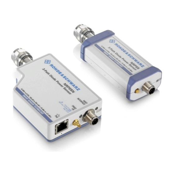
Figure 4-1, the USB power sensor is shown on the left, the LAN power sensor is shown on the right. Figure 4-1: R&S NRP series power sensors (example) 1 = RF connector, see Chapter 4.1, "RF connector", on page 27 2 = Status LED, see Chapter 4.2, "Status... -
Page 28: Status Information
® Power sensor tour R&S NRPxxS(N) Status information Table 4-1: R&S NRPxxS(N) RF connector characteristics Power sensor Male connector Matching female con- Tightening torque nector R&S NRP8S R&S NRP8SN 1.36 Nm (12'' lbs) R&S NRP18S R&S NRP18SN R&S NRP33S R&S NRP33SN 3.50 mm 3.50 mm/ 2.92 mm/ SMA R&S NRP33SN-V... -
Page 29: Host Interface
® Power sensor tour R&S NRPxxS(N) LAN PoE interface Indication State Slow flashing red Static error You can query the error type with SYSTem:SERRor?. Fast flashing red Critical static error You can query the error type with SYSTem:SERRor?. Note: If this state occurs after a firmware update, the update was not successful. - Page 30 ® Power sensor tour R&S NRPxxS(N) LAN PoE interface Power over Ethernet status LED The power status LED shows whether the sensor is correctly powered over PoE or not. Color State Green The sensor is powered over PoE. You can operate it using the Ethernet interface. No light No PoE power is present.
-
Page 31: Operating Concepts
® Operating concepts R&S NRPxxS(N) R&S NRP Toolkit 5 Operating concepts For operating the power sensor, you can choose from various possibilities: ● Chapter 5.2, "Browser-based user interface", on page 34 ● Chapter 5.3, "Remote control", on page 36 ● Chapter 5.4, "R&S NRPV", on page 36... -
Page 32: R&S Nrp Toolkit For Windows
® Operating concepts R&S NRPxxS(N) R&S NRP Toolkit Supported Microsoft Windows versions: ● Microsoft Windows Vista 32/64-bit ● Microsoft Windows 7 32/64-bit ● Microsoft Windows 8/ 8.1 32/64-bit ● Microsoft Windows 10 32/64-bit 5.1.3 R&S NRP Toolkit for Windows The R&S NRP Toolkit installer for Windows-based systems contains the components described in the release notes available at www.rohde-schwarz.com/software/nrp-tool- kit. - Page 33 ® Operating concepts R&S NRPxxS(N) R&S NRP Toolkit 3. Accept the license terms to continue with the installation. 4. Click "Next" and complete the installation process. 5.1.3.1 Components of the R&S NRP Toolkit Access: "Start" > "NRP-Toolkit" The following tools are part of the R&S NRP Toolkit for Windows. Configure Network Sensor Useful if you have troubles establishing a LAN connection with an R&S NRP LAN power sensor.
-
Page 34: Browser-Based User Interface
® Operating concepts R&S NRPxxS(N) Browser-based user interface NRP Version Display Displays version information of all installed, power measurement-relevant software packages. R&S NRP‑Z Uncertainty Calculator Determines the expanded measurement uncertainty. The tool comes with a manual (PDF) that is also available in the "Start" menu. S-Parameter Update Multi Helps loading an S-parameter table into the power sensor. - Page 35 ® Operating concepts R&S NRPxxS(N) Browser-based user interface Setup HOST INTERFACE TRIG2 3 V or 5 V logic OUT: min. 2 V into 50 Ω max. 5.3 V SMART SENSOR TECHNOLOGY Figure 5-1: Setup with the web user interface = Signal source = LAN power sensor = RJ-45 Ethernet connector 4, 6 = RJ-45 Ethernet cable...
-
Page 36: Remote Control
® Operating concepts R&S NRPxxS(N) R&S NRPV The main dialog of the web user interface opens. 3. Select the "Continuous Average" tab and perform any necessary changes. 4. Press "Measurement > ON" to start the measurement. For a detailed description of the web user interface, refer to Chapter 6, "Browser-based user interface",... - Page 37 ® Operating concepts R&S NRPxxS(N) R&S NRPV ● Windows computer with installed: – R&S NRP Toolkit V 4.20 or higher – R&S NRPV version 3.2 or higher (refer to the operating manual of the R&S NRPV for a description of the installation process) Setup 3-Path Diode Power Sensor MHz to GHz, 100 pW to 200 mW (−70 dBm to +23 dBm)
-
Page 38: R&S Power Viewer
® Operating concepts R&S NRPxxS(N) R&S Power Viewer 5.5 R&S Power Viewer The R&S Power Viewer is software that simplifies many measurement tasks. It is provi- ded on your documentation CD-ROM and on the Rohde & Schwarz website as a sepa- rate standalone installation package. -
Page 39: R&S Power Viewer Mobile
Store. ® The 1MA215 "Using R&S NRP Series Power Sensors with Android Handheld Devi- ces" application note gives a detailed description on installation and features of the R&S Power Viewer Mobile. The application note is provided on the documentation CD- ROM and at: www.rohde-schwarz.com/application/nrpz... - Page 40 ® Operating concepts R&S NRPxxS(N) R&S NRX Setup 3-Path Diode Power Sensor MHz to GHz, 100 pW to 200 mW (−70 dBm to +23 dBm) SMART SENSOR TECHNOLOGY Figure 5-4: Setup with an R&S NRX base unit 1 = Signal source 2 = R&S NRPxxS(N) power sensor 3 = Host interface connector 4 = R&S NRP‑ZK8 cable...
- Page 41 ® Operating concepts R&S NRPxxS(N) R&S NRX 4. Switch on the signal source. The measurement starts, and the result is displayed in dBm. 5. If necessary, perform further settings. User Manual 1177.5079.02 ─ 15...
-
Page 42: Browser-Based User Interface
® Browser-based user interface R&S NRPxxS(N) Main dialog of the web user interface 6 Browser-based user interface The web user interface is an alternative way to operate an R&S NRPxxSN LAN power sensor. This chapter provides a description of the parameters used for setting a power mea- surement with the web user interface. -
Page 43: Setting The Unit
® Browser-based user interface R&S NRPxxS(N) Setting the unit Result pane Displays the measurement result for the selected measurement mode. It can display only a value or a graph, depending on the selected measurement mode. 6.2 Setting the unit You can set the unit for the different parameters by typing the corresponding letter after the entered value. -
Page 44: Common Settings
® Browser-based user interface R&S NRPxxS(N) Common settings Watts, dBm or dBµV. To change the unit, you must specify the desired value together with the full new unit once. Example: To change the representation of a "Trigger Level" of 100µW into dBm, enter -10dbm in the "Trigger Level"... -
Page 45: Measurement Modes
® Browser-based user interface R&S NRPxxS(N) Measurement modes <Value> ← Offset Adds a fixed level offset in dB to account for external losses. Remote command: [SENSe<Sensor>:]CORRection:OFFSet S-Parameter Selects the mode used for the S-parameters. S-parameters are used to compensate for a component (attenuator, directional coupler) connected ahead of the sensor. See also Chapter 9.8.4.3, "S-parameter correction",... -
Page 46: Continuous Average Mode
® Browser-based user interface R&S NRPxxS(N) Measurement modes ● Continuous average mode..................46 ● Burst average mode....................47 ● Timeslot mode......................47 ● Trace mode......................48 6.4.1 Continuous average mode Describes the parameters of the continuous average measurement. Further information: ● Chapter 9.7.1, "Continuous average measurement", on page 91 Detailed description of the continuous average mode and its remote commands... -
Page 47: Burst Average Mode
® Browser-based user interface R&S NRPxxS(N) Measurement modes 6.4.2 Burst average mode Describes the parameters of the burst average measurement. Further information: ● Chapter 9.7.2, "Burst average measurement", on page 94 Detailed description of the burst average mode and its remote commands Access: main dialog of the web user interface >... -
Page 48: Trace Mode
® Browser-based user interface R&S NRPxxS(N) Measurement modes Number of Timeslots..................... 48 Nominal Width.......................48 Start Exclude.........................48 Exclude........................48 Number of Timeslots Sets the number of simultaneously measured timeslots. Up to eight slots can be selected. Remote command: [SENSe<Sensor>:][POWer:]TSLot[:AVG]:COUNt Nominal Width Sets the length of a timeslot in seconds. -
Page 49: Settings
® Browser-based user interface R&S NRPxxS(N) Settings Trace Time........................49 Trace Offset Time......................49 Trace Points........................49 Trace Time Sets the trace length. Remote command: [SENSe<Sensor>:]TRACe:TIME Trace Offset Time Sets the relative position of the trigger event in relation to the beginning of the trace measurement sequence. - Page 50 ® Browser-based user interface R&S NRPxxS(N) Settings Range..........................50 Γ Correction........................50 └ <State>......................50 └ Magnitude....................... 50 └ Phase......................50 Zero Calibration......................50 Sensor Information......................51 Range Selects which path of the sensor is used for the measurement. Remote command: on page 71 [SENSe<Sensor>:]RANGe:AUTO on page 70 [SENSe<Sensor>:]RANGe Γ...
-
Page 51: Averaging Settings
® Browser-based user interface R&S NRPxxS(N) Settings Turn off all test signals before zeroing. An active test signal during zeroing causes an error. Remote command: CALibration<Channel>:ZERO:AUTO Sensor Information Displays information on the power sensor. ● General information: manufacturer, sensor type, stock number, serial number, firm- ware version ●... -
Page 52: Trigger Settings
® Browser-based user interface R&S NRPxxS(N) Settings Auto Measurement Time Available only if "Noise Content" is set under "<Mode>" on page 45. Sets an upper limit for the settling time of the auto-averaging filter, thus limiting the length of the filter. Remote command: [SENSe<Sensor>:]AVERage:COUNt:AUTO:MTIMe 6.5.3 Trigger settings... -
Page 53: System Settings
® Browser-based user interface R&S NRPxxS(N) Settings Remote command: TRIGger:SLOPe Trigger Level Sets the trigger threshold for internal triggering derived from the test signal. Remote command: on page 86 TRIGger:LEVel on page 87 TRIGger:LEVel:UNIT Trigger Delay Sets the delay between the trigger event and the beginning of the actual measurement. Remote command: TRIGger:DELay Dropout... - Page 54 ® Browser-based user interface R&S NRPxxS(N) Settings Address........................54 Subnet Mask......................... 54 Sensor Name........................ 54 Gateway........................54 DHCP..........................54 Selftest.......................... 55 Apply Network Settings....................55 Firmware Update......................56 IP Address Sets the IP address of the sensor. Remote command: SYSTem:COMMunicate:NETWork:IPADdress Subnet Mask Sets the subnet mask.
- Page 55 ® Browser-based user interface R&S NRPxxS(N) Settings "Static" Enables assigning the IP address manually. Remote command: SYSTem:COMMunicate:NETWork:IPADdress:MODE Selftest Starts a selftest of the sensor. See also Chapter 9.11, "Testing", on page 126. Note: Do not apply a signal to the sensor while the selftest is running. If the selftest is carried out with a signal being present, error messages can erroneously be output for the test steps Offset Voltages and/or Noise Voltages.
- Page 56 ® Browser-based user interface R&S NRPxxS(N) Settings Firmware Update Opens a dialog to start the firmware update. For further information, see Chapter 7.2.2, "Using the web user interface", on page 59. Alternatively, you can the Firmware Update for NRP Family program. See Chap- ter 7.2.1, "Using the Firmware Update for NRP Family program",...
-
Page 57: Firmware Update
® Firmware update R&S NRPxxS(N) Updating the firmware 7 Firmware update ● Hardware and software requirements..............57 ● Updating the firmware..................... 57 7.1 Hardware and software requirements For performing a firmware update, the system requirements are as follows: ● Connectors and cables for establishing a connection to the computer: Chapter 3.7.1, "Computer", on page 18. - Page 58 ® Firmware update R&S NRPxxS(N) Updating the firmware Firmware Update for NRP Family A firmware update can take up to 5 minutes. Ensure that the update is not interrupted. 1. Check the prerequisites. See "Checking the prerequisites" on page 57. 2.
-
Page 59: Using The Web User Interface
® Firmware update R&S NRPxxS(N) Updating the firmware 8. Check if the update was successful. The firmware version in the "Identification" field must match the version you selected in the "Firmware" field. Troubleshooting You do not find the sensor in the list of sensors provided by Firmware Update for NRP Family. -
Page 60: Using Remote Control
® Firmware update R&S NRPxxS(N) Updating the firmware 7. Click "Start update". The firmware update can take several minutes. During the update process, a pro- gress bar is displayed. When the update is completed, the dialog closes automati- cally. 7.2.3 Using remote control If you want to integrate a firmware update function in an application, use SYSTem: on page 129. - Page 61 ® Firmware update R&S NRPxxS(N) Updating the firmware In this example, you write exactly 10242905 bytes to the power sensor, for example by using a 'viWrite()' function. The 10242905 bytes result from the values of the list above: 9 + 1 + 1 + 1 + 8 + 10242884 + 1 In a (pseudo) string notation, the memory block looks as follows: SYST:FWUP #810242884<file_contents>0x0a, User Manual 1177.5079.02 ─...
-
Page 62: Replacing An R&S Nrp-Zxx With An R&Snrpxxs(N)
® Replacing an R&S NRP‑Zxx with an R&S NRPxxS(N) R&S NRPxxS(N) Prerequisites 8 Replacing an R&S NRP‑Zxx with an R&S NRPxxS(N) The R&S NRPxxS(N) power sensors are compatible with the R&S NRP‑Zxx series of power sensors. R&S NRPxx power sensor Replaces R&S NRP‑Zxx power sensor R&S NRP8S / R&S NRP8SN - USB connected R&S NRP-Z11... - Page 63 ® Replacing an R&S NRP‑Zxx with an R&S NRPxxS(N) R&S NRPxxS(N) Prerequisites After the new version of the R&S NRP Toolkit is installed, you can connect the R&S NRPxxS(N) to the computer and use it with Rohde & Schwarz software applications or your own programs.
-
Page 64: Remote Control Commands
® Remote control commands R&S NRPxxS(N) Conventions used in SCPI command descriptions 9 Remote control commands In the following, all commands implemented in the sensor are listed according to the command system and then described in detail. Mostly, the notation used complies with SCPI specifications. -
Page 65: Notations
® Remote control commands R&S NRPxxS(N) Notations Basic unit Also noted as degrees Angle Percent dBuV DBUV 9.2 Notations For a detailed description of SCPI notations, see Chapter 11, "Remote control basics", on page 151. Numeric suffixes <n> If a command can be applied to multiple instances of an object, e.g. specific sensors, the required instances can be specified by a suffix added to the command. -
Page 66: Common Commands
® Remote control commands R&S NRPxxS(N) Common commands Example: Definition: [SENSe<Sensor>:]AVERage:COUNt:AUTO:NSRatio <nsr> Command: AVER:COUN:AUTO:NSR 0.01 Special characters | and { } A vertical bar in parameter definitions indicates alternative possibilities in the sense of "or". The effect of the command differs, depending on which parameter is used. Example: Definition: INITiate:CONTinuous ON | OFF Command INITiate:CONTinuous ON starts the measurements... -
Page 67: Idn
® Remote control commands R&S NRPxxS(N) Common commands The command does not alter the ENABle and TRANsition parts of the registers. Usage: Event *ESE <register> Event status enable Sets the event status enable register to the specified value. The query returns the con- tents of the event status enable register in decimal form. -
Page 68: Opt
® Remote control commands R&S NRPxxS(N) Common commands *OPC? basically functions like *WAI, but also returns a response. The response is an advantage, because you can query the execution of commands from a controller pro- gram before sending new commands. Thus preventing overflow of the input queue when too many commands are sent that cannot be executed. -
Page 69: Stb
® Remote control commands R&S NRPxxS(N) Common commands Setting parameters: <number> Range: 0 to 9 *RST: Usage: Setting only *SRE <register> Service request enable Sets the service request enable register to the specified value. This command deter- mines under which conditions a service request is triggered. Parameters: <register>... -
Page 70: Preparing For The Measurement
® Remote control commands R&S NRPxxS(N) Preparing for the measurement Usage: Event 9.4 Preparing for the measurement Before starting a measurement, you need to do the following: ● Selecting the reference source................70 ● Selecting a measurement path................70 ● Selecting a measurement mode................ -
Page 71: Selecting A Measurement Mode
® Remote control commands R&S NRPxxS(N) Preparing for the measurement 0 is the most sensitive path. 2 is the most insensitive path. 1 is the path with medium sensitivity. Range: 0 to 2 *RST: Manual operation: "Range" on page 50 [SENSe<Sensor>:]RANGe:AUTO <state>... -
Page 72: Configuring The Measured Values
® Remote control commands R&S NRPxxS(N) Preparing for the measurement "POWer:TSLot:AVG" Timeslot mode Chapter 9.7.3, "Timeslot measurement", on page 96. "XTIMe:POWer" Trace mode Chapter 9.7.4, "Trace measurement", on page 98. *RST: "POWer:AVG" 9.4.4 Configuring the measured values Before starting a measurement, you can configure the measurand or enable the mea- surement of additional-measured values. -
Page 73: Controlling The Measurement
® Remote control commands R&S NRPxxS(N) Controlling the measurement Parameters: <mode> *RST: "POWer:AVERage" Example: The following sequence of commands configures a peak trace measurement: *RST SENSe:FUNCtion "XTIMe:POWer" SENSe:FREQuency 1.0e9 SENSe:TRACe:POINts 500 SENS:TRAC:TIME 20e-3 TRIGger:SOURce INTernal TRIGger:SLOPe POSitive TRIGger:DTIMe 0.001 TRIGger:HYSTeresis 0.1 TRIGger:LEVel 30e-6 SENSe:TRACe:AVERage:COUNt 8 SENSe:TRACe:AVERage:STATe ON... -
Page 74: Starting And Ending A Measurement
® Remote control commands R&S NRPxxS(N) Controlling the measurement ● Do you want to output each new average value as a measurement result or do you want to bundle more measured values into one result? 9.5.1 Starting and ending a measurement .......................... -
Page 75: Triggering
® Remote control commands R&S NRPxxS(N) Controlling the measurement Measurements are performed continuously. If a measurement is completed, the sensor does not return to the idle state but enters the waiting for trigger state again. Ends the continuous measurement mode, and sets the sensor to the idle state. - Page 76 ® Remote control commands R&S NRPxxS(N) Controlling the measurement ● INITiate[:IMMediate] The number of measurement cycles is restricted. 1 is set, the command starts a single measurement cycle that TRIGger:COUNt renders one result. Every time you send this command, a new measurement cycle is started.
- Page 77 ® Remote control commands R&S NRPxxS(N) Controlling the measurement Figure 9-1: Significance of the dropout time 1 = Dropout time 2 = Trigger hysteresis 3 = Trigger level The RF power between the slots is below the threshold defined by the trigger level and the trigger hysteresis.
-
Page 78: Controlling The Measurement Results
® Remote control commands R&S NRPxxS(N) Controlling the measurement 1 = Hold-off time 2 = Trigger hysteresis 3 = Trigger level 9.5.3 Controlling the measurement results The R&S NRPxxS(N) can cope with the wide range of measurement scenarios with the help of the so-called "termination control". -
Page 79: Interplay Of The Controlling Mechanisms
® Remote control commands R&S NRPxxS(N) Controlling the measurement 9.5.4 Interplay of the controlling mechanisms In the following examples, continuous measurement scenarios are used. But these scenarios apply also to single measurements. The only difference is that a single mea- surement is not repeated. - Page 80 ® Remote control commands R&S NRPxxS(N) Controlling the measurement Example: Moving termination control Further settings for this example: ● [SENSe<Sensor>:]AVERage:TCONtrol MOVing ● TRIGger:COUNt Every measurement is started by a trigger event. Due to the chopper phases, one measurement lasts twice the defined aperture time. During each measurement, the trigger synchronization is high (TRIGger:SYNC:STATe ON).
- Page 81 ® Remote control commands R&S NRPxxS(N) Controlling the measurement Example: Average count = 1 [SENSe<Sensor>:]AVERage:COUNt For average count 1, the setting of the termination control has no impact. In both cases, the measurement runs for the duration of one aperture time. Then, settled data is available, and the power sensor returns to the idle state.
- Page 82 ® Remote control commands R&S NRPxxS(N) Controlling the measurement Example: Moving termination control Further settings for this example: ● [SENSe<Sensor>:]TRACe:AVERage:TCONtrol MOVing Every chopper phase is started by a trigger event and lasts the defined trace time. Dur- ing a chopper phase, the trigger synchronization is high (TRIGger:SYNC:STATe ON).
-
Page 83: Configuring The Trigger
® Remote control commands R&S NRPxxS(N) Controlling the measurement 9.5.5 Configuring the trigger Further information: ● Chapter 9.5, "Controlling the measurement", on page 73 Remote commands: ....................83 TRIGger:ATRigger:DELay ..................83 TRIGger:ATRigger:EXECuted? ....................84 TRIGger:ATRigger[:STATe] ......................84 TRIGger:COUNt ....................... 84 TRIGger:DELay ..................... 84 TRIGger:DELay:AUTO ....................... -
Page 84: Trigger:atrigger[:State]
® Remote control commands R&S NRPxxS(N) Controlling the measurement TRIGger:ATRigger[:STATe] <state> Effective only in trace mode and, irrespective of the set averaging factor, only one trace is recorded. Controls the automatic trigger function. If enabled, an artificial trigger is generated if the delay time has elapsed after the measurement start and no trigger event has occurred. -
Page 85: Trigger:dtime
® Remote control commands R&S NRPxxS(N) Controlling the measurement Parameters: <state> *RST: TRIGger:DTIMe <dropout_time> Sets the dropout time for the internal trigger source. During this time, the signal power must exceed (negative trigger slope) or undercut (positive trigger slope) the level defined by the trigger level and trigger hysteresis. -
Page 86: Trigger:hysteresis
® Remote control commands R&S NRPxxS(N) Controlling the measurement TRIGger:HYSTeresis <hysteresis> Sets the hysteresis. A trigger event occurs, if the trigger level: ● Falls below the set value on a rising slope. ● Rises above the set value on a falling slope Thus, you can use this setting to eliminate the effects of noise in the signal for the edge detector of the trigger system. -
Page 87: Trigger:level:unit
® Remote control commands R&S NRPxxS(N) Controlling the measurement TRIGger:LEVel:UNIT <unit> Sets the unit of the trigger level if this value is entered without a unit. See also on page 86. TRIGger:LEVel Parameters: <unit> DBM | W | DBUV *RST: Manual operation: "Trigger Level"... -
Page 88: Trigger:source
® Remote control commands R&S NRPxxS(N) Controlling the measurement Determines which edge of the envelope power, with internal triggering, or increasing voltage, with external triggering, is used for triggering. Parameters: <slope> POSitive | NEGative POSitive Rising edge NEGative Falling edge *RST: POSitive Manual operation:... -
Page 89: Configuring Results
® Remote control commands R&S NRPxxS(N) Configuring results 9.6 Configuring results See also: ● Chapter 9.9, "Querying measurement results", on page 123 9.6.1 Setting the power unit The UNIT subsystem contains commands for setting up the power unit. UNIT:POWer <unit> Sets the output unit for the measured power values. -
Page 90: Configuring The Measurement Modes
® Remote control commands R&S NRPxxS(N) Configuring the measurement modes FORMat:SREGister <sregister> Specifies which format is used for the return value of *STB?. Parameters: <sregister> ASCii | HEXadecimal | OCTal | BINary *RST: ASCii Example: FORM:SREG ASC FORMat[:DATA] [<data,length>, <length>] Specifies how the R&S NRPxxS(N) sends the numeric data to the controlling host/ computer. -
Page 91: Continuous Average Measurement
® Remote control commands R&S NRPxxS(N) Configuring the measurement modes Contents: ● Continuous average measurement................. 91 ● Burst average measurement...................94 ● Timeslot measurement....................96 ● Trace measurement....................98 9.7.1 Continuous average measurement The continuous average mode measures the signal average power asynchronously within definable time intervals (sampling windows). -
Page 92: [Sense
® Remote control commands R&S NRPxxS(N) Configuring the measurement modes Accelerating measurements Using ON, you can accelerate the mea- [SENSe<Sensor>:][POWer:][AVG:]FAST surement as follows: ● Chopper is disabled. ● Average count is set to 1, no matter which average count you have set. Thus, the overall measurement time is only defined by the aperture time, and the mea- surement time for a fast measurement is calculated as follows: MT = APER...:][Power:][Avg:]Aperture -
Page 93: [Sense
® Remote control commands R&S NRPxxS(N) Configuring the measurement modes [SENSe<Sensor>:][POWer:][AVG:]BUFFer:COUNt? Available in continuous average mode. Queries the number of results that are currently stored in the result buffer. Example: BUFF:COUN? Usage: Query only [SENSe<Sensor>:][POWer:][AVG:]BUFFer:DATA? Queries the results of the continuous average result buffer and returns them even if the buffer is not full.:][Power:][Avg:]Buffer:count -
Page 94: Burst Average Measurement
® Remote control commands R&S NRPxxS(N) Configuring the measurement modes [SENSe<Sensor>:][POWer:][AVG:]FAST <state> Enables or disables a fast unchopped continuous average measurement. If enabled, the average count is enforced to 1, and any setting for average count is silently ignored. You can increase the measurement accuracy by increasing the duration of the sam- pling window using: [SENSe<Sensor>:][POWer:][AVG:]APERture. - Page 95 ® Remote control commands R&S NRPxxS(N) Configuring the measurement modes Trigger level Pulse interval Time Dropout tolerance Dropout time Figure 9-2: Burst average parameters To prevent power drops due to modulation from being erroneously interpreted as the end of a pulse, you must define the dropout tolerance. The dropout tolerance is a time interval in which the pulse end is only recognized if the signal level no longer exceeds the trigger level.
-
Page 96: Timeslot Measurement
® Remote control commands R&S NRPxxS(N) Configuring the measurement modes [SENSe<Sensor>:][POWer:]BURSt:LENGth? Queries the length of a burst (pulse interval), the time between the trigger point of the measurement and the time the trigger logic detects the end of the pulse. See Fig- 9-2. - Page 97 ® Remote control commands R&S NRPxxS(N) Configuring the measurement modes ..............97 [SENSe<Sensor>:][POWer:]TSLot[:AVG]:COUNt ..............97 [SENSe<Sensor>:][POWer:]TSLot[:AVG]:WIDTh ......97 [SENSe<Sensor>:][POWer:]TSLot[:AVG][:EXCLude]:MID:OFFSet[:TIME] ..........97 [SENSe<Sensor>:][POWer:]TSLot[:AVG][:EXCLude]:MID:TIME ........98 [SENSe<Sensor>:][POWer:]TSLot[:AVG][:EXCLude]:MID[:STATe] [SENSe<Sensor>:][POWer:]TSLot[:AVG]:COUNt <count> Sets the number of simultaneously measured timeslots in timeslot mode. See Fig- 9-3. Parameters: <count> Range: 1 to 128 *RST: Manual operation:...
-
Page 98: Trace Measurement
® Remote control commands R&S NRPxxS(N) Configuring the measurement modes [SENSe<Sensor>:][POWer:]TSLot[:AVG][:EXCLude]:MID[:STATe] <state> Enables or disables the blanking out of time intervals in the timeslots. Parameters: <state> *RST: 9.7.4 Trace measurement The trace measurement determines the course of power over a defined time. During the measurement time set by [SENSe<Sensor>:]TRACe:TIME, a large number of measurements are performed. - Page 99 ® Remote control commands R&S NRPxxS(N) Configuring the measurement modes MOVing Outputs intermediate values to facilitate early detection of changes in the measured quantity. In the settled state, that means when the number of measurements specified by the average count has been performed, a moving average is output. REPeat Specifies that a measurement result is not output until the entire measurement has been completed.
- Page 100 ® Remote control commands R&S NRPxxS(N) Configuring the measurement modes Header Starting character Single digit that defines how many of the following digits are interpreted as the size of the content. LLLLL Number consisting of as many digits as specified by "n". This number gives the size of the content.
- Page 101 ® Remote control commands R&S NRPxxS(N) Configuring the measurement modes If no measurands have been activated before exe- [SENSe<Sensor>:]AUXiliary cuting the measurement, the user data content is finished here. In case that auxiliary measurands have been selected, the above section is repeated for every auxiliary measurand.
-
Page 102: Configuring Basic Measurement Parameters
® Remote control commands R&S NRPxxS(N) Configuring basic measurement parameters Manual operation: "Trace Points" on page 49 [SENSe<Sensor>:]TRACe:REALtime <state> Available in trace mode. If disabled, each measurement from the power sensor is averaged. If enabled, only one sampling sequence per measurement is recorded, thus increasing the measure- ment speed. - Page 103 ® Remote control commands R&S NRPxxS(N) Configuring basic measurement parameters .................105 [SENSe<Sensor>:]AVERage:RESet ............105 [SENSe<Sensor>:]AVERage:COUNt:AUTO:TYPE ................105 [SENSe<Sensor>:]AVERage:TCONtrol ................106 [SENSe<Sensor>:]AVERage[:STATe] [SENSe<Sensor>:]AVERage:COUNt <count> Sets the number of readings that are averaged for one measured value. The higher the count, the lower the noise, and the longer it takes to obtain a measured value. Average count is often also called averaging factor, but it designates the same thing, i.e the number of measured values that have to be averaged for forming the measure- ment result.
- Page 104 ® Remote control commands R&S NRPxxS(N) Configuring basic measurement parameters Parameters: <maximum_time> Range: 0.01 to 999.99 *RST: 4.00 Default unit: Seconds Manual operation: "Auto Measurement Time" on page 52 [SENSe<Sensor>:]AVERage:COUNt:AUTO:NSRatio <nsr> Determines the relative noise component in the measurement result for the measure- ment modes with scalar results.
- Page 105 ® Remote control commands R&S NRPxxS(N) Configuring basic measurement parameters Parameters: <slot> Range: 1 to 128 *RST: [SENSe<Sensor>:]AVERage:RESet Deletes all previous measurement results that the averaging filter contains and initial- izes the averaging filter. The filter length gradually increases from 1 to the set averag- ing factor.
-
Page 106: Setting The Frequency
® Remote control commands R&S NRPxxS(N) Configuring basic measurement parameters MOVing Outputs intermediate values to facilitate early detection of changes in the measured quantity. In the settled state, that means when the number of measurements specified by the average count has been performed, a moving average is output. REPeat Specifies that a measurement result is not output until the entire measurement has been completed. -
Page 107: Excluding Intervals
® Remote control commands R&S NRPxxS(N) Configuring basic measurement parameters 9.8.3 Excluding intervals In the burst average and timeslot modes, you can define a time interval at the begin- ning or at the end of an integration interval that is excluded from the measurement result. -
Page 108: Configuring Corrections
® Remote control commands R&S NRPxxS(N) Configuring basic measurement parameters Parameters: <exclude_stop> Range: 0.0 to 1.0 *RST: Default unit: Seconds Manual operation: "End Exclude" on page 47 "End Exclude" on page 48 9.8.4 Configuring corrections It is possible to set some parameters that compensate for a change of the measured signal due to fixed external influences. -
Page 109: Offset Corrections
® Remote control commands R&S NRPxxS(N) Configuring basic measurement parameters Parameters: <state> *RST: Manual operation: "Duty Cycle" on page 46 9.8.4.2 Offset corrections The offset accounts for external losses by adding a fixed level offset in dB. The attenuation of an attenuator located ahead of the sensor (or the coupling attenua- tion of a directional coupler) is considered with a positive offset. - Page 110 ® Remote control commands R&S NRPxxS(N) Configuring basic measurement parameters All R&S NRPxxS(N) power sensors allow compensating for the influence of any 2-port device between the signal source and the power sensor input. As a result, the firmware can calculate the power that the signal source actually delivers. Examples of such 2- port devices include attenuators, matching pads, minimum-loss pads and waveguide adapters.
-
Page 111: S-Gamma Corrections
® Remote control commands R&S NRPxxS(N) Configuring basic measurement parameters 9.8.4.4 S-gamma corrections Using the complex reflection coefficient, you can determine the power P delivered by the signal source with considerably greater accuracy. The coefficient of the signal source Γ is defined by its magnitude and phase: source ●... -
Page 112: I-Gamma Queries
® Remote control commands R&S NRPxxS(N) Configuring basic measurement parameters [SENSe<Sensor>:]SGAMma:CORRection:STATe <state> Enables or disables the use of the complex reflection coefficient to correct the interac- tions of power sensor and signal source. Parameters: <state> *RST: Manual operation: "<State>" on page 50 [SENSe<Sensor>:]SGAMma:MAGNitude <magnitude>... -
Page 113: Using The S-Parameters Program
® Remote control commands R&S NRPxxS(N) Configuring basic measurement parameters Example: IGAM:MAGN? Query 1.739179E-02 Response Usage: Query only [SENSe<Sensor>:]IGAMma:PHASe? Queries the phase angle of the complex input reflection coefficient Γ . The result is provided in degrees. Range: -180 degrees to +180 degrees. Example: IGAM:PHAS? Query... -
Page 114: Menu Bar
® Remote control commands R&S NRPxxS(N) Configuring basic measurement parameters User interface of the S-Parameters program Figure 9-9: S-Parameters dialog Menu bar........................114 └ File........................ 114 └ Sensor......................115 └ Device......................115 └ Options......................115 └ User Data....................115 └ Remote....................115 └ Show Cal. -
Page 115: Sensor
® Remote control commands R&S NRPxxS(N) Configuring basic measurement parameters Sensor ← Menu bar Provides options for loading and saving calibration data directly from or to the sensor, see: ● "To load a calibration data set from a power sensor" on page 117 ●... -
Page 116: Global Flags
® Remote control commands R&S NRPxxS(N) Configuring basic measurement parameters Figure 9-10: Example Global Flags Groups the settings for the power sensor behavior regarding S-parameter corrections. S-Parameter Correction ON by Default ← Global Flags If this option is enabled, the S-parameter correction is activated automatically when the sensor is started. -
Page 117: Use Flags In Factory Cal. Data Set
® Remote control commands R&S NRPxxS(N) Configuring basic measurement parameters Use Flags in Factory Cal. Data Set ← Global Flags Available if the power sensor supports two different calibration data sets: ● Factory calibration data set containing all factory calibration data. ●... - Page 118 ® Remote control commands R&S NRPxxS(N) Configuring basic measurement parameters The "Upload Calibration Data" dialog opens. It shows a list of the available sen- sors. 3. If you cannot find your power sensor in the list, for example because of reconnect- ing the power sensor, you can reload the list by clicking "Rebuild List".
- Page 119 ® Remote control commands R&S NRPxxS(N) Configuring basic measurement parameters 6. Create a backup of the calibration data set before making any changes. Select "File" > "Save Calibration Data". A dialog opens where you can select the location to save the calibration data. To change the S-parameter data 1.
- Page 120 ® Remote control commands R&S NRPxxS(N) Configuring basic measurement parameters 5. If needed, load uncertainty data. See "To load an uncertainty parameter file" on page 120. 6. Check the entries in the " S-Parameter Device Mnemonic", "Lower Power Limit/W" and "Upper Power Limit/W" fields 7.
- Page 121 ® Remote control commands R&S NRPxxS(N) Configuring basic measurement parameters To save the calibration data to the sensor 1. Select "Sensor" > "Save Calibration Data". The "Download Calibration Data" dialog opens. 2. Confirm that the correct power sensor is selected by clicking "Download". After a successful transfer of the data to the power sensor, a confirmation message is displayed.
- Page 122 ® Remote control commands R&S NRPxxS(N) Configuring basic measurement parameters ● Option line The option line has the format #[<frequency unit>][<parameter>][<format>][<R n>], where: – Identifies the option line. – <frequency unit> Possible values are Hz, kHz, MHz or GHz. If a frequency unit is not specified, GHz is implicitly assumed.
-
Page 123: Querying Measurement Results
® Remote control commands R&S NRPxxS(N) Querying measurement results – <parameter> U must be specified for uncertainty data files. If a parameter is not specified, S is implicitly assumed and as a result an error message is triggered. – <format> This value is ignored in uncertainty measurement files. -
Page 124: Calibrating, Zeroing
® Remote control commands R&S NRPxxS(N) Calibrating, zeroing FETCh<Sensor>[:SCALar][:POWer][:AVG]? Queries the last valid measurement result of the measurand that was configured before. To configure the measurand, use before the measurement is initi- CALCulate:FEED ated. Usage: Query only FETCh<Sensor>[:SCALar][:POWer]:BURSt? Queries the last valid measurement result in burst average mode. To configure the measurand, use before the measurement is initi- CALCulate:FEED... - Page 125 ® Remote control commands R&S NRPxxS(N) Calibrating, zeroing ......................125 CALibration:DATA .................... 125 CALibration:DATA:LENGth? ....................125 CALibration:USER:DATA .................. 125 CALibration:USER:DATA:LENGth? ................126 CALibration<Channel>:ZERO:AUTO CALibration:DATA <caldata> Writes a binary calibration data set in the memory of the power sensor. Parameters: <caldata> <block_data> CALibration:DATA:LENGth? Queries the length in bytes of the calibration data set currently stored in the flash mem- ory.
-
Page 126: Testing
® Remote control commands R&S NRPxxS(N) Testing CALibration<Channel>:ZERO:AUTO <state> Performs zero calibration. Turn off all test signals before zeroing. An active test signal during zeroing causes an error. While zero calibration is in progress, no queries or other setting commands are allowed, since the command is synchronous. -
Page 127: Configuring The System
® Remote control commands R&S NRPxxS(N) Configuring the system TEST:SENSor? [<Item>] Starts a selftest of the power sensor. In contrast to *TST?, this command returns detailed information that you can use for troubleshooting. Query parameters: <Item> String Usage: Query only Manual operation: "Selftest"... -
Page 128: System:dfprint
® Remote control commands R&S NRPxxS(N) Configuring the system .................... 135 SYSTem:TRANsaction:END ....................135 SYSTem[:SENSor]:NAME ......................136 SYSTem:VERSion? SYSTem:DFPRint<Channel>? Reads the footprint file of the power sensor. Suffix: <Channel> 1...4 Measurement channel if more than one channel is available. Usage: Query only SYSTem:ERRor:ALL? Queries all unread entries in the SCPI communication error queue and removes them from the queue. -
Page 129: System:error:count
® Remote control commands R&S NRPxxS(N) Configuring the system Example: SYST:ERR:CODE? Query Response: No errors have occurred since the error queue was last read out. Usage: Query only SYSTem:ERRor:COUNt? Queries the number of entries in the SCPI communication error queue. Example: SYST:ERR:COUN? Query... -
Page 130: System:fwupdate:status
® Remote control commands R&S NRPxxS(N) Configuring the system 0x0a as appended delimiter for line feed Usage: Setting only Manual operation: "Firmware Update" on page 56 SYSTem:FWUPdate:STATus? Reads the result of the firmware update performed using SYSTem:FWUPdate on page 129. While a firmware update is in progress, the LED of the power sensor flashes in bright white color. -
Page 131: System:info
® Remote control commands R&S NRPxxS(N) Configuring the system SYSTem:INFO? [<item>] Queries information about the power sensor. If queried without parameters, the command returns all available information in the form of a list of strings separated by commas. If you want to query specific information, add the query parameter: SYST:INFO? "<string>"... -
Page 132: System:led:mode
® Remote control commands R&S NRPxxS(N) Configuring the system 0x0krrggbb with k = 0: steady on; k = 1: slowly flashing; k = 2: fast flashing rr = red gg = green bb = blue In NRP legacy communication, the parameter is a standard deci- mal number, representing the corresponding hexadecimal code. -
Page 133: System:parameters:delta
® Remote control commands R&S NRPxxS(N) Configuring the system ● Minimum value ● Maximum value ● Parameters ● Limits Each command is shortened to a command token, consisting only of the mnemonics short form. For example, CALibration:DATA is shortened to CALDATA as command token. -
Page 134: System:serror
® Remote control commands R&S NRPxxS(N) Configuring the system Sets the result update time. That is the maximum rate in which the power sensor can output measurement results. Parameters: <update_time> Range: 0.0 to 10.0 *RST: Default unit: Seconds SYSTem:SERRor? Queries the next static error, if available. Static errors occur when you select conflicting settings. -
Page 135: System:sutime
® Remote control commands R&S NRPxxS(N) Configuring the system Example: SYST:SERR:LIST? Query 0,"reported at uptime:2942; notice; auto-averaging exceeded maximum time; Notification" Response Usage: Query only SYSTem:SUTime <update_time> Effective only in the NRP legacy mode. Relevant only in continuous measurement mode, INITiate:CONTinuousON. Sets the status update time. -
Page 136: Configuring Lan Network Properties
® Remote control commands R&S NRPxxS(N) Configuring the system Figure 9-11: Sensor name displayed in the web user interface Parameters: <sensorname> Example: SYST:NAME "InputModule-X5" Manual operation: "Sensor Name" on page 54 SYSTem:VERSion? Queries the SCPI version that the command set of the power sensor complies with. Example: SYST:VERS? Query... - Page 137 ® Remote control commands R&S NRPxxS(N) Configuring the system Restarts the network connection to the DUT, that means terminates the connection and sets it up again. Example: SYST:COMM:NETW:REST Usage: Event SYSTem:COMMunicate:NETWork:RESet Effective only for the R&S NRP LAN power sensors. Resets the LAN network settings to the default values.
- Page 138 ® Remote control commands R&S NRPxxS(N) Configuring the system The power sensor performs the change of the hostname immediately after the com- mand is sent. For this purpose, the power sensor restarts its connection to the network, which can take several seconds. During this time, you cannot address the power sen- sor.
-
Page 139: Using The Status Register
® Remote control commands R&S NRPxxS(N) Using the status register Queries the network status information. Usage: Query only SYSTem:COMMunicate:NETWork:IPADdress:MODE <mode> Effective only for the R&S NRP LAN power sensors. Sets whether the IP address is assigned automatically or manually. Parameters: <mode>... -
Page 140: General Status Register Commands
® Remote control commands R&S NRPxxS(N) Using the status register ● Controlling the ENABle part.................. 141 ● Controlling the negative transition part..............141 ● Controlling the positive transition part..............142 9.13.1 General status register commands ......................140 STATus:PRESet ....................140 STATus:QUEue[:NEXT]? STATus:PRESet Resets the edge detectors and ENABle parts of all registers to a defined value. -
Page 141: Controlling The Enable Part
® Remote control commands R&S NRPxxS(N) Using the status register STATus:OPERation:LLFail[:SUMMary][:EVENt]? STATus:OPERation:MEASuring[:SUMMary][:EVENt]? STATus:OPERation:SENSe[:SUMMary][:EVENt]? STATus:OPERation:TRIGger[:SUMMary][:EVENt]? STATus:OPERation:ULFail[:SUMMary][:EVENt]? STATus:QUEStionable:CALibration[:SUMMary][:EVENt]? STATus:QUEStionable[:EVENt]? STATus:QUEStionable:POWer[:SUMMary][:EVENt]? STATus:QUEStionable:WINDow[:SUMMary][:EVENt]? Usage: Query only 9.13.4 Controlling the ENABle part STATus:DEVice:ENABle <value> STATus:OPERation:CALibrating:ENABle <value> STATus:OPERation:ENABle <value> STATus:OPERation:LLFail:ENABle <value> STATus:OPERation:MEASuring:ENABle <value> STATus:OPERation:SENSe:ENABle <value> STATus:OPERation:TRIGger:ENABle <value> STATus:OPERation:ULFail:ENABle <value>... -
Page 142: Controlling The Positive Transition Part
® Remote control commands R&S NRPxxS(N) Using the status register 9.13.6 Controlling the positive transition part STATus:DEVice:PTRansition <value> STATus:OPERation:CALibrating:PTRansition <value> STATus:OPERation:PTRansition <value> STATus:OPERation:LLFail:PTRansition <value> STATus:OPERation:MEASuring:PTRansition <value> STATus:OPERation:SENSe:PTRansition <value> STATus:OPERation:TRIGger:PTRansition <value> STATus:OPERation:ULFail:PTRansition <value> STATus:QUEStionable:CALibration:PTRansition <value> STATus:QUEStionable:PTRansition <value> STATus:QUEStionable:POWer:PTRansition <value> STATus:QUEStionable:WINDow:PTRansition <value> Parameters: <value>... -
Page 143: Performing Measurement Tasks - Programming Examples
® Performing measurement tasks - programming examples R&S NRPxxS(N) Performing the fastest measurement in continuous average mode 10 Performing measurement tasks - program- ming examples If you install the optional software development kit (SDK) of the R&S NRP Toolkit, pro- gramming examples are provided. - Page 144 ® Performing measurement tasks - programming examples R&S NRPxxS(N) Performing the fastest measurement in continuous average mode write( '*RST' ) # Enable fast unchopped continuous average measurement write( 'SENS:POW:AVG:FAST ON' ) # Define output format (float) write( 'FORM:DATA REAL,32' ) # Select the trigger condition.
-
Page 145: Triggered Fast Unchopped Continuous Average Measurement
® Performing measurement tasks - programming examples R&S NRPxxS(N) Performing the fastest measurement in continuous average mode 10.2.2 Triggered fast unchopped continuous average measurement This example, written in pseudo code, shows how to set up and execute a fast unchop- ped continuous average measurement. -
Page 146: Performing A Buffered Continuous Average Measurement
// or 'EXT Trigger' --> false bool bUseBUSTrigger = true; // Use the first NRP series sensor which is found if ( VI_SUCCESS == SENSOR.openFirstNrpSensor( "USB?::0X0AAD::?*::INSTR" ) ) //Start with a clean state SENSOR.write( "*RST" ); // Auto Averaging OFF and set Average Count = 4 SENSOR.write( "SENS:AVER:COUN:AUTO OFF"... - Page 147 ® Performing measurement tasks - programming examples R&S NRPxxS(N) Performing a buffered continuous average measurement // Buffer size is randomly selected to 17 SENSOR.write( "SENS:BUFF:SIZE 17" ); SENSOR.write( "SENS:BUFF:STAT ON" ); SENSOR.write( "TRIG:COUN 17" ); // Read out all errors / Clear error queue SENSOR.query( "SYST:ERR:ALL?", szBuf, sizeof( szBuf ) );...
-
Page 148: Performing Trace Measurements
® Performing measurement tasks - programming examples R&S NRPxxS(N) Performing trace measurements 10.4 Performing trace measurements *RST //Set the sensor's operation mode to trace SENSe:FUNCtion "XTIMe:POWer" //Set the carrier frequency SENSe:FREQuency 1.8e9 //Set the number of points for the trace measurement //Using 500 points usually represents a good compromise //between USB transfer speed and resolution SENSe:TRACe:POINTs 500... -
Page 149: Trace Measurement With Synchronization To Measurement Complete
® Performing measurement tasks - programming examples R&S NRPxxS(N) Trace measurement with synchronization to measurement complete 10.5 Trace measurement with synchronization to measure- ment complete This example, written in pseudo code, shows how to set up and execute a trace mea- surement using a non-blocking technique. - Page 150 ® Performing measurement tasks - programming examples R&S NRPxxS(N) Trace measurement with synchronization to measurement complete // (this loop could also check for cancel-requests from the user or other break conditions) while ( ! bMeasReady ) query( "STAT:OPER:MEAS:EVEN?", &iEvent ); bMeasReady = ((iEvent &...
-
Page 151: Remote Control Basics
® Remote control basics R&S NRPxxS(N) Remote control interfaces and protocols 11 Remote control basics For general information on remote control of Rohde & Schwarz products via SCPI, refer to www.rohde-schwarz.com/rc-via-scpi. 11.1 Remote control interfaces and protocols For remote control, communication between the R&S NRPxxS(N) power sensors and the controlling host is established based on various interfaces and protocols. - Page 152 ® Remote control basics R&S NRPxxS(N) Remote control interfaces and protocols Besides USBTMC, the NRP legacy protocol is available to ensure the compatibility of the R&S NRPxxS(N) power sensors with the R&S NRP‑Z series of power sensors. The usage of this protocol is not recommended for new applications. The resource string represents an addressing scheme that is used to establish a com- munication session with the sensor.
-
Page 153: Ethernet Interface
® Remote control basics R&S NRPxxS(N) Remote control interfaces and protocols 11.1.2 Ethernet interface The Ethernet interface of the R&S NRP LAN power sensors allows you to integrate them in a local area network (LAN). For remote control via a network, the computer and the power sensor must be connec- ted via the Ethernet interface to a common network with TCP/IP network protocol. -
Page 154: Status Reporting System
® Remote control basics R&S NRPxxS(N) Status reporting system Socket communication TCPIP::<IP address or hostname>::port::SOCKET ● port determines the used port number ● SOCKET indicates the raw network socket resource class Socket communication requires the specification of the port (commonly referred to as port number) and of "SOCKET"... - Page 155 ® Remote control basics R&S NRPxxS(N) Status reporting system Status byte Error queue Device status Questionable status Standard event status RQS/MSS Operation status Message queue Figure 11-1: Status registers overview 1 = Status byte, see Table 11-3 Chapter 11.2.2, "Device status register", on page 157 Chapter 11.2.3, "Questionable status...
- Page 156 ® Remote control basics R&S NRPxxS(N) Status reporting system Short description Bit is set if Questionable status register An EVENt bit is set in the QUEStionable status register and summary the associated ENABLe bit is set to 1. A set bit denotes a ques- tionable device status which can be specified in greater detail by querying the questionable status register.
-
Page 157: Device Status Register
® Remote control basics R&S NRPxxS(N) Status reporting system 11.2.2 Device status register Sensor error summary Sensor error Sensor error Sensor error Sensor error Legacy locked Reference PLL locked Figure 11-2: Device status register Querying the register: ● STATus:DEVice:CONDition? ● STATus:DEVice[:EVENt]? Querying the static errors: ●... -
Page 158: Questionable Status Register
® Remote control basics R&S NRPxxS(N) Status reporting system Bit no. Short description Bit is set if Legacy locked state The power sensor is locked in the NRP legacy mode. Via the SCPI channels (USBTMC or TCP/IP), only query commands can be sent, but no setting commands. - Page 159 ® Remote control basics R&S NRPxxS(N) Status reporting system Power summary Calibration summary POST failure Figure 11-3: Questionable status register Querying the register: ● STATus:QUEStionable:CONDition? ● STATus:QUEStionable[:EVENt]? Table 11-5: Used questionable status bits and their meaning Bit no. Short description Bit is set if Power summary Summary of...
- Page 160 ® Remote control basics R&S NRPxxS(N) Status reporting system Sensor power Sensor please zero Figure 11-4: Questionable power status register Querying the register: ● STATus:QUEStionable:POWer:CONDition? ● STATus:QUEStionable:POWer[:SUMMary][:EVENt]? Table 11-6: Used questionable power status bits and their meaning Bit no. Short description Bit is set if Sensor power Measurement data of the power sensor is corrupt.
-
Page 161: Standard Event Status And Enable Register (Esr, Ese)
® Remote control basics R&S NRPxxS(N) Status reporting system Sensor calibration Figure 11-5: Questionable calibration status register Querying the register: ● STATus:QUEStionable:CALibration:CONDition? ● STATus:QUEStionable:CALibration[:SUMMary][:EVENt]? Table 11-7: Used questionable calibration status bits and their meaning Bit no. Short description Bit is set if Sensor calibration Zeroing of the power sensor was not successful. -
Page 162: Operation Status Register
® Remote control basics R&S NRPxxS(N) Status reporting system Operation Complete Query Error Device-Dependent Error Execution Error Command Error User Request Power On Figure 11-6: Standard event status register (ESR) Table 11-8: Used standard event status bits and their meaning Bit no. - Page 163 ® Remote control basics R&S NRPxxS(N) Status reporting system Calibrating Measuring Triggering Sense summary Lower limit fail Upper limit fail Figure 11-7: Operation status register Querying the register: ● STATus:OPERation:CONDition? ● STATus:OPERation[:EVENt]? Table 11-9: Used operation status bits and their meaning Bit no.
- Page 164 ® Remote control basics R&S NRPxxS(N) Status reporting system Sensor calibrating Figure 11-8: Operation calibrating status register Querying the register: ● STATus:OPERation:CALibrating:CONDition? ● STATus:OPERation:CALibrating[:SUMMary][:EVENt]? Table 11-10: Used operation calibrating status bits and their meaning Bit no. Short description Bit is set if Sensor calibrating Sensor is being calibrated.
- Page 165 ® Remote control basics R&S NRPxxS(N) Status reporting system Sensor measuring Figure 11-9: Operation measuring status register Querying the register: ● STATus:OPERation:MEASuring:CONDition? ● STATus:OPERation:MEASuring[:SUMMary][:EVENt]? Table 11-11: Used operation measuring status bits and their meaning Bit no. Short description Bit is set if Sensor measuring Sensor is measuring.
- Page 166 ® Remote control basics R&S NRPxxS(N) Status reporting system Sensor waiting for trigger Figure 11-10: Operation trigger status register Querying the register: ● STATus:OPERation:TRIGger:CONDition? ● STATus:OPERation:TRIGger[:SUMMary][:EVENt]? Table 11-12: Used operation trigger status bits and their meaning Bit no. Short description Bit is set if Sensor waiting for trigger Sensor is waiting for a trigger event.
- Page 167 ® Remote control basics R&S NRPxxS(N) Status reporting system Sensor initializing Figure 11-11: Operation sense status register Querying the register: ● STATus:OPERation:SENSe:CONDition? ● STATus:OPERation:SENSe[:SUMMary][:EVENt]? Table 11-13: Used operation sense status bits and their meaning Bit no. Short description Bit is set if Sensor initializing Sensor is being initialized.
- Page 168 ® Remote control basics R&S NRPxxS(N) Status reporting system Lower limit fail Figure 11-12: Operation lower limit fail status registers Querying the register: ● STATus:OPERation:LLFail:CONDition? ● STATus:OPERation:LLFail[:SUMMary][:EVENt]? Table 11-14: Used operation lower limit fail status bits and their meaning Bit no. Short description Bit is set if Lower limit fail...
- Page 169 ® Remote control basics R&S NRPxxS(N) Status reporting system Upper limit fail Figure 11-13: Operation upper limit fail status registers Querying the register: ● STATus:OPERation:ULFail:CONDition? ● STATus:OPERation:ULFail[:SUMMary][:EVENt]? Table 11-15: Used operation upper limit fail status bits and their meaning Bit no. Short description Bit is set if Upper limit fail...
-
Page 170: Troubleshooting
® Troubleshooting R&S NRPxxS(N) Performing a selftest 12 Troubleshooting ● Displaying status information................170 ● Performing a selftest..................... 170 ● Problems during a firmware update..............171 ● Cannot establish a LAN connection..............171 ● Contacting customer support................171 12.1 Displaying status information Status information is available in several ways. -
Page 171: Problems During A Firmware Update
® Troubleshooting R&S NRPxxS(N) Contacting customer support See also "Selftest" on page 55. 12.3 Problems during a firmware update The firmware update is described in Chapter 7, "Firmware update", on page 57. Solutions for potential problems that can occur when using the Firmware Update for NRP Family, see "Troubleshooting"... - Page 172 ® Troubleshooting R&S NRPxxS(N) Contacting customer support Contact information Contact our customer support center at www.rohde-schwarz.com/support, or follow this QR code: Figure 12-1: QR code to the Rohde & Schwarz support page User Manual 1177.5079.02 ─ 15...
-
Page 173: Transporting
® Transporting R&S NRPxxS(N) 13 Transporting Packing Use the original packaging material. It consists of antistatic wrap for electrostatic pro- tection and packing material designed for the product. If you do not have the original packaging, use similar materials that provide the same level of protection. -
Page 174: Maintenance, Storage And Disposal
® Maintenance, storage and disposal R&S NRPxxS(N) Regular checks 14 Maintenance, storage and disposal It is advisable to check the nominal data from time to time. 14.1 Regular checks If the power sensor is used frequently, check the RF connectors for visible damage - bent inner conductors, broken contact springs and so on. -
Page 175: Cleaning
® Maintenance, storage and disposal R&S NRPxxS(N) Disposal 14.2 Cleaning 1. Disconnect the R&S NRPxxS(N) : a) From the DUT. b) From the computer or base unit. 2. Clean the outside of the R&S NRPxxS(N) using a lint-free cloth. You can dampen the cloth with water but keep in mind that the casing is not waterproof. - Page 176 ® Maintenance, storage and disposal R&S NRPxxS(N) Disposal Rohde & Schwarz has developed a disposal concept for the eco-friendly disposal or recycling of waste material. As a manufacturer, Rohde & Schwarz completely fulfills its obligation to take back and dispose of electrical and electronic waste. Contact your local service representative to dispose of the product.
-
Page 177: List Of Commands
® List of commands R&S NRPxxS(N) List of commands [SENSe<Sensor>:][POWer:][AVG:]APERture....................92 [SENSe<Sensor>:][POWer:][AVG:]BUFFer:CLEar..................92 [SENSe<Sensor>:][POWer:][AVG:]BUFFer:COUNt?..................93 [SENSe<Sensor>:][POWer:][AVG:]BUFFer:DATA?..................93 [SENSe<Sensor>:][POWer:][AVG:]BUFFer:SIZE....................93 [SENSe<Sensor>:][POWer:][AVG:]BUFFer:STATe..................93 [SENSe<Sensor>:][POWer:][AVG:]FAST......................94 [SENSe<Sensor>:][POWer:][AVG:]SMOothing:STATe..................94 [SENSe<Sensor>:][POWer:]BURSt:DTOLerance................... 95 [SENSe<Sensor>:][POWer:]BURSt:LENGth?....................96 [SENSe<Sensor>:][POWer:]TSLot[:AVG]:COUNt................... 97 [SENSe<Sensor>:][POWer:]TSLot[:AVG]:WIDTh....................97 [SENSe<Sensor>:][POWer:]TSLot[:AVG][:EXCLude]:MID:OFFSet[:TIME].............97 [SENSe<Sensor>:][POWer:]TSLot[:AVG][:EXCLude]:MID:TIME..............97 [SENSe<Sensor>:][POWer:]TSLot[:AVG][:EXCLude]:MID[:STATe]..............98 [SENSe<Sensor>:]AUXiliary..........................73 [SENSe<Sensor>:]AVERage:COUNt......................103 [SENSe<Sensor>:]AVERage:COUNt:AUTO....................103 [SENSe<Sensor>:]AVERage:COUNt:AUTO:MTIMe..................103 [SENSe<Sensor>:]AVERage:COUNt:AUTO:NSRatio................... 104 [SENSe<Sensor>:]AVERage:COUNt:AUTO:RESolution................ - Page 178 ® List of commands R&S NRPxxS(N) [SENSe<Sensor>:]TRACe:AVERage:COUNt....................98 [SENSe<Sensor>:]TRACe:AVERage:TCONtrol....................98 [SENSe<Sensor>:]TRACe:AVERage[:STATe]....................99 [SENSe<Sensor>:]TRACe:DATA?........................99 [SENSe<Sensor>:]TRACe:MPWidth?......................101 [SENSe<Sensor>:]TRACe:OFFSet:TIME......................101 [SENSe<Sensor>:]TRACe:POINts........................ 101 [SENSe<Sensor>:]TRACe:REALtime......................102 [SENSe<Sensor>:]TRACe:TIME........................102 *CLS.................................66 *ESE................................67 *ESR?................................67 *IDN?................................67 *IST?................................67 *OPC................................67 *OPT?................................68 *PRE................................68 *RCL................................68 *RST................................68 *SAV.................................68 *SRE................................69 *STB?................................69 *TRG................................69 *TST?................................69...
- Page 179 ® List of commands R&S NRPxxS(N) STATus:OPERation:CALibrating:PTRansition....................142 STATus:OPERation:CALibrating[:SUMMary][:EVENt]?................. 140 STATus:OPERation:CONDition?........................140 STATus:OPERation:ENABle.......................... 141 STATus:OPERation:LLFail:CONDition?......................140 STATus:OPERation:LLFail:ENABle....................... 141 STATus:OPERation:LLFail:NTRansition......................141 STATus:OPERation:LLFail:PTRansition......................142 STATus:OPERation:LLFail[:SUMMary][:EVENt]?..................141 STATus:OPERation:MEASuring:CONDition?....................140 STATus:OPERation:MEASuring:ENABle.......................141 STATus:OPERation:MEASuring:NTRansition....................141 STATus:OPERation:MEASuring:PTRansition....................142 STATus:OPERation:MEASuring[:SUMMary][:EVENt]?..................141 STATus:OPERation:NTRansition........................141 STATus:OPERation:PTRansition........................142 STATus:OPERation:SENSe:CONDition?.......................140 STATus:OPERation:SENSe:ENABle......................141 STATus:OPERation:SENSe:NTRansition...................... 141 STATus:OPERation:SENSe:PTRansition...................... 142 STATus:OPERation:SENSe[:SUMMary][:EVENt]?..................141 STATus:OPERation:TRIGger:CONDition?.....................140 STATus:OPERation:TRIGger:ENABle......................
- Page 180 ® List of commands R&S NRPxxS(N) STATus:QUEStionable:WINDow:PTRansition....................142 STATus:QUEStionable:WINDow[:SUMMary][:EVENt]?.................141 STATus:QUEStionable[:EVENt]?........................141 STATus:QUEue[:NEXT]?..........................140 SYSTem:COMMunicate:NETWork:IPADdress....................138 SYSTem:COMMunicate:NETWork:IPADdress:GATeway................138 SYSTem:COMMunicate:NETWork:IPADdress:INFO?...................138 SYSTem:COMMunicate:NETWork:IPADdress:MODE...................139 SYSTem:COMMunicate:NETWork:IPADdress:SUBNet:MASK..............139 SYSTem:COMMunicate:NETWork:RESet..................... 137 SYSTem:COMMunicate:NETWork:RESTart....................136 SYSTem:COMMunicate:NETWork:STATus?....................137 SYSTem:COMMunicate:NETWork[:COMMon]:DOMain................137 SYSTem:COMMunicate:NETWork[:COMMon]:HOSTname................137 SYSTem:DFPRint<Channel>?........................128 SYSTem:ERRor:ALL?............................128 SYSTem:ERRor:CODE:ALL?........................128 SYSTem:ERRor:CODE[:NEXT]?........................128 SYSTem:ERRor:COUNt?..........................129 SYSTem:ERRor[:NEXT]?..........................129 SYSTem:FWUPdate............................129 SYSTem:FWUPdate:STATus?........................
- Page 181 ® List of commands R&S NRPxxS(N) TRIGger:COUNt...............................84 TRIGger:DELay............................... 84 TRIGger:DELay:AUTO............................ 84 TRIGger:DTIMe............................... 85 TRIGger:EXTernal<2...2>:IMPedance......................85 TRIGger:HOLDoff............................85 TRIGger:HYSTeresis............................86 TRIGger:IMMediate............................86 TRIGger:LEVel..............................86 TRIGger:LEVel:UNIT............................87 TRIGger:SENDer:PORT..........................87 TRIGger:SENDer:STATe..........................87 TRIGger:SLOPe...............................87 TRIGger:SOURce............................88 TRIGger:SYNC:PORT............................. 88 TRIGger:SYNC:STATe.............................88 UNIT:POWer..............................89 User Manual 1177.5079.02 ─ 15...
-
Page 182: Index
® Index R&S NRPxxS(N) Index Offset ................ 109 S-gamma ..............111 Android device S-parameter .............. 109 R&S Power Viewer Mobile .......... 39 Customer support ............171 Application cards ............... 13 Application notes ............... 13 Auto averaging ..............102 Data sheets ............... 13 Device status register ............ - Page 183 ® Index R&S NRPxxS(N) Installation Firmware ..............57 Instrument security procedures ......... 12 Offset ................109 Intended use ............... 9 Open source acknowledgment (OSA) ....... 13 Operating concepts ............31 Interface Overview ..............27 App for Android devices ..........39 Browser-based user interface ........
- Page 184 ® Index R&S NRPxxS(N) R&S NRX ................39 Special characters R&S Power Viewer ............38 SCPI ................66 Standard event status register ........161 R&S Power Viewer Mobile ..........39 Status information ............170 Reference source Status LED ................ 28 Remote control ............
- Page 185 ® Index R&S NRPxxS(N) USB resource string ............152 USB sensor hub ..............19 User manual ..............12 Versions of R&S NRP software ......... 34 VISA ................153 VXI-11 ................153 Warning message ............. 10 Web user interface ............42 Main dialog ..............42 White papers ..............
Need help?
Do you have a question about the NRP Series and is the answer not in the manual?
Questions and answers