Table of Contents
Advertisement
Quick Links
Advertisement
Chapters
Table of Contents

Related Manuals for R&S NRP P Series


Summary of Contents for R&S NRP P Series
- Page 1 ® R&S NRPxxP Pulse Power Sensors User Manual (;ÝÇÊ2) 1179576002 Version 02...
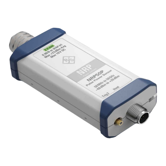
- Page 2 This manual describes the following pulse power sensors with firmware version FW 01.10 and later: ● ® R&S NRP18P (1444.1190K02) ● ® R&S NRP40P (1444.1290K02) ● ® R&S NRP50P (1444.1390K02) © 2022 Rohde & Schwarz GmbH & Co. KG Muehldorfstr. 15, 81671 Muenchen, Germany Phone: +49 89 41 29 - 0 Email: info@rohde-schwarz.com...
-
Page 3: Table Of Contents
® Contents R&S NRPxxP Contents 1 Safety and regulatory information............7 Safety instructions......................7 Labels on the product....................8 Warning messages in the documentation..............8 2 Welcome....................9 Documentation overview....................9 2.1.1 Getting started manual....................9 2.1.2 User manuals........................9 2.1.3 Tutorials...........................9 2.1.4 Instrument security procedures..................9 2.1.5 Basic safety instructions....................9 2.1.6... - Page 4 ® Contents R&S NRPxxP 5 Operating concepts................20 R&S NRP Toolkit......................20 5.1.1 Versions and downloads....................20 5.1.2 System requirements....................20 5.1.3 R&S NRP Toolkit for Windows..................21 Remote control......................22 R&S NRPV........................23 R&S Power Viewer...................... 24 R&S NRX........................26 6 Firmware update.................. 28 Preparing the update....................
- Page 5 ® Contents R&S NRPxxP 8.6.2 Burst average measurement..................58 8.6.3 Timeslot measurement....................59 8.6.4 Trace measurement...................... 61 8.6.5 Pulse analysis measurement..................66 8.6.6 Statistics measurement....................70 Configuring basic measurement parameters............74 8.7.1 Configuring auto averaging................... 74 8.7.2 Setting the frequency....................77 8.7.3 Excluding intervals......................78 8.7.4 Configuring corrections....................
- Page 6 ® Contents R&S NRPxxP Performing a buffered continuous average measurement........120 Performing trace measurements................122 Trace measurement with synchronization to measurement complete....123 10 Remote control basics...............125 10.1 Remote control interfaces and protocols............... 125 10.1.1 USB interface......................125 10.2 Status reporting system................... 126 10.2.1 Overview........................
-
Page 7: Safety And Regulatory Information
® Safety and regulatory information R&S NRPxxP Safety instructions 1 Safety and regulatory information The product documentation helps you use the product safely and efficiently. Follow the instructions provided here and in the following chapters. Intended use The power sensors are intended for accurate and uncomplicated power measurements in production, R&D and calibration labs as well as for installation and maintenance tasks. -
Page 8: Labels On The Product
® Safety and regulatory information R&S NRPxxP Warning messages in the documentation aged or broken, stop using the product. Contact Rohde & Schwarz customer service at https://www.rohde-schwarz.com/support. Operating the product Only use the product indoors. The product casing is not waterproof. Observe the ambient conditions such as altitude, operating temperature and climatic loads;... -
Page 9: Welcome
® Welcome R&S NRPxxP Documentation overview 2 Welcome This chapter provides an overview of the user documentation and an introduction to the R&S NRPxxP. 2.1 Documentation overview This section provides an overview of the R&S NRPxxP user documentation. Unless specified otherwise, you find the documents at: www.rohde-schwarz.com/manual/nrpxxp Further documents are available at: www.rohde-schwarz.com/product/nrpxxp... -
Page 10: Data Sheets And Brochures
® Welcome R&S NRPxxP Key features 2.1.6 Data sheets and brochures The data sheet contains the technical specifications of the R&S NRPxxP. It also lists the firmware applications and their order numbers, and optional accessories. The brochure provides an overview of the instrument and deals with the specific char- acteristics. -
Page 11: Preparing For Use
® Preparing for use R&S NRPxxP Choosing the operating site 3 Preparing for use Here, you can find basic information about setting up the product for the first time. ● Unpacking and checking..................11 ● Choosing the operating site..................11 ● Considerations for test setup.................. -
Page 12: Considerations For Test Setup
® Preparing for use R&S NRPxxP Connecting to a DUT 3.3 Considerations for test setup Give particular attention to the following aspects when handling power sensors. EMI impact on measurement results Electromagnetic interference (EMI) can affect the measurement results. To suppress electromagnetic radiation during operation: ●... -
Page 13: Powering The Power Sensor
® Preparing for use R&S NRPxxP Connecting a cable to the host interface 3-Path Diode Power Sensor MHz to GHz, 100 pW to 200 mW (−70 dBm to +23 dBm) SMART SENSOR TECHNOLOGY 4. NOTICE! Risk of damaging the center pin of the RF connector. Only rotate the hex nut of the RF connector. -
Page 14: Connecting To A Controlling Host
® Preparing for use R&S NRPxxP Connecting to a controlling host 2. Tighten the union nut manually. To disconnect the host interface of the power sensor 1. Loosen the union nut of the screw-lock cable connector. 2. Remove the cable. 3.7 Connecting to a controlling host As a controlling host, you can use: ●... - Page 15 ® Preparing for use R&S NRPxxP Connecting to a controlling host Setup 3-Path Diode Power Sensor MHz to GHz, 100 pW to 200 mW (−70 dBm to +23 dBm) SMART SENSOR TECHNOLOGY ‑ ZKU cable Figure 3-1: Setup with an R&S NRP 1 = Signal source 2 = R&S NRPxxP power sensor 3 = Host interface connector...
- Page 16 ® Preparing for use R&S NRPxxP Connecting to a controlling host Setup Figure 3-2: Setup with an R&S NRP-Z5 sensor hub 1 = External power supply unit 2 = Connect to AC power supply. 3 = Connect to computer with USB host interface. 4 = Optional: Connect to trigger source.
-
Page 17: Base Unit
® Preparing for use R&S NRPxxP Connecting to a controlling host 5. Connect the delivered external power supply unit to the R&S NRP‑Z5 and to an AC supply connector. 6. Connect the trigger input of the R&S NRP‑Z5 with a BNC cable to the trigger source (optional). -
Page 18: Power Sensor Tour
® Power sensor tour R&S NRPxxP RF connector 4 Power sensor tour This chapter provides an overview of the available connectors and LEDs of the power sensor. Figure 4-1: R&S NRPxxP power sensors (example) 1 = RF connector, see Chapter 4.1, "RF connector", on page 18 2 = Status LED, see... -
Page 19: Status Information
® Power sensor tour R&S NRPxxP Trigger I/O connector 4.2 Status information The status LED gives information about the state of the power sensor. The following states are defined: Indication State White Idle state. The power sensor performs no measurement and is ready for use. -
Page 20: Operating Concepts
® Operating concepts R&S NRPxxP R&S NRP Toolkit 5 Operating concepts For operating the power sensor, you can choose from various possibilities: ● Chapter 5.2, "Remote control", on page 22 ● Chapter 5.3, "R&S NRPV", on page 23 ● Chapter 5.4, "R&S Power Viewer", on page 24 ●... -
Page 21: R&S Nrp Toolkit For Windows
® Operating concepts R&S NRPxxP R&S NRP Toolkit ● Microsoft Windows 10 32/64-bit 5.1.3 R&S NRP Toolkit for Windows The R&S NRP Toolkit installer for Windows-based systems contains the components described in the release notes available at www.rohde-schwarz.com/software/nrp-tool- kit. To install the R&S NRP Toolkit 1. -
Page 22: Remote Control
® Operating concepts R&S NRPxxP Remote control 4. Click "Next" and complete the installation process. 5.1.3.1 Components of the R&S NRP Toolkit Access: "Start" > "NRP-Toolkit" The following tools are part of the R&S NRP Toolkit for Windows. Configure Network Sensor Useful if you have troubles establishing a LAN connection with an R&S NRP LAN power sensor. -
Page 23: R&S Nrpv
® Operating concepts R&S NRPxxP R&S NRPV Further information: ● Chapter 8, "Remote control commands", on page 33 ● Chapter 10, "Remote control basics", on page 125 ● Chapter 10.1, "Remote control interfaces and protocols", on page 125 ● Chapter 3.7.1, "Computer", on page 14 5.3 R&S NRPV... -
Page 24: R&S Power Viewer
® Operating concepts R&S NRPxxP R&S Power Viewer nect the power sensor as described in Chapter 3.4, "Connecting to a DUT", on page 12. Connect the power sensor to the signal source. 2. Connect the power sensor to the computer as shown in Figure 5-1. - Page 25 ® Operating concepts R&S NRPxxP R&S Power Viewer Setup 3-Path Diode Power Sensor MHz to GHz, 100 pW to 200 mW (−70 dBm to +23 dBm) SMART SENSOR TECHNOLOGY Figure 5-2: Setup with the R&S Power Viewer 1 = Signal source 2 = R&S NRPxxP power sensor 3 = Host interface connector 4 = R&S NRP‑ZKU cable...
-
Page 26: R&S Nrx
® Operating concepts R&S NRPxxP R&S NRX 5.5 R&S NRX In a measurement, the R&S NRX uses all power sensor-dependent measurement functions and displays the results. Thus, you can configure both the measurement and the power sensor. Required equipment ● R&S NRPxxP power sensor ●... - Page 27 ® Operating concepts R&S NRPxxP R&S NRX a) Switch off the power of the signal source. b) Press the [Zero] key of the R&S NRX. c) Tap "Zero All Sensors". 3. Configure the measurement. a) In the "Measurement Settings" dialog, select the "Measurement Type", for example "Continuous Average".
-
Page 28: Firmware Update
® Firmware update R&S NRPxxP Updating the firmware 6 Firmware update ● Preparing the update....................28 ● Updating the firmware..................... 28 6.1 Preparing the update Firmware of R&S power sensors generally has an *.rsu extension, RSU meaning Rohde & Schwarz update. To download the update file 1. - Page 29 ® Firmware update R&S NRPxxP Updating the firmware 2. Ensure that the R&S NRP Toolkit for Windows is installed on the computer. See Chapter 5.1, "R&S NRP Toolkit", on page 20. To update the firmware A firmware update can take up to 5 minutes. Ensure that the update is not interrupted. 1.
-
Page 30: Using Remote Control
® Firmware update R&S NRPxxP Updating the firmware During the update process, a progress bar is displayed. The update sequence can take a couple of minutes, depending on the power sensor model and the size of the selected file. 8. Check if the update was successful. The firmware version in the "Identification" field must match the version you selected in the "Firmware"... - Page 31 ® Firmware update R&S NRPxxP Updating the firmware Example: You want to update your R&S NRP40P with the NRPxP_02.30.21062301.rsu file. This file has a size of 10242884 bytes. To send the file to the power sensor for updating the firmware, your application has to assemble a memory block containing: SYST:FWUP <block_data>...
-
Page 32: Replacing An R&S Nrp-Zxx With An R&Snrpxxp
® Replacing an R&S NRP‑Zxx with an R&S NRPxxP R&S NRPxxP Prerequisites 7 Replacing an R&S NRP‑Zxx with an R&S NRPxxP The R&S NRPxxP power sensors are compatible with the R&S NRP‑Zxx series of power sensors. R&S NRPxx power sensor Replaces R&S NRP‑Zxx power sensor R&S NRP18P R&S NRP-Z81... -
Page 33: Remote Control Commands
® Remote control commands R&S NRPxxP Conventions used in SCPI command descriptions 8 Remote control commands In the following, all implemented commands are listed according to the command sys- tem and then described in detail. Mostly, the notation used complies with SCPI specifi- cations. -
Page 34: Notations
® Remote control commands R&S NRPxxP Notations Basic unit Also noted as degrees Angle Percent dBuV DBUV 8.2 Notations For a detailed description of SCPI notations, see Chapter 10, "Remote control basics", on page 125. Numeric suffixes <n> If a command can be applied to multiple instances of an object, e.g. specific power sensors, the required instances can be specified by a suffix added to the command. -
Page 35: Common Commands
® Remote control commands R&S NRPxxP Common commands Example: Definition: [SENSe<Sensor>:]AVERage:COUNt:AUTO:NSRatio <nsr> Command: AVER:COUN:AUTO:NSR 0.01 Special characters | and { } A vertical bar in parameter definitions indicates alternative possibilities in the sense of "or". The effect of the command differs, depending on which parameter is used. Example: Definition: INITiate:CONTinuous ON | OFF Command INITiate:CONTinuous ON starts the measurements... -
Page 36: Ese
® Remote control commands R&S NRPxxP Common commands The command does not alter the ENABle and TRANsition parts of the registers. Usage: Event *ESE <register> Event status enable Sets the event status enable register to the specified value. The query returns the con- tents of the event status enable register in decimal form. -
Page 37: Opt
® Remote control commands R&S NRPxxP Common commands *OPC? basically functions like *WAI, but also returns a response. The response is an advantage, because you can query the execution of commands from a controller pro- gram before sending new commands. Thus preventing overflow of the input queue when too many commands are sent that cannot be executed. -
Page 38: Sre
® Remote control commands R&S NRPxxP Common commands Setting parameters: <number> Range: 0 to 9 *RST: Usage: Setting only *SRE <register> Service request enable Sets the service request enable register to the specified value. This command deter- mines under which conditions a service request is triggered. Parameters: <register>... -
Page 39: Preparing For The Measurement
® Remote control commands R&S NRPxxP Preparing for the measurement Usage: Event 8.4 Preparing for the measurement Before starting a measurement, you need to do the following: ● Selecting a measurement mode................39 ● Configuring the measured values................40 8.4.1 Selecting a measurement mode ►... -
Page 40: Configuring The Measured Values
® Remote control commands R&S NRPxxP Preparing for the measurement 8.4.2 Configuring the measured values Before starting a measurement, you can configure the measurand or enable the mea- surement of additional-measured values......................40 CALCulate:FEED ....................41 SENSe<Sensor>:AUXiliary CALCulate:FEED <mode> If you query measurement data using FETCh<Sensor>[:SCALar][:POWer][: AVG]?, the power sensor returns data of the measurand that was configured before. -
Page 41: Controlling The Measurement
® Remote control commands R&S NRPxxP Controlling the measurement SENSe<Sensor>:AUXiliary <mode> Enables the measurement of additional-measured values that are determined together with the main-measured value. Parameters: <mode> NONE | MINMax | RNDMax NONE No additional values are measured. MINMax Minima and maxima of the trace are transmitted together with the measured value. -
Page 42: Triggering
® Remote control commands R&S NRPxxP Controlling the measurement Usage: Event INITiate:ALL INITiate[:IMMediate] Starts a single measurement cycle. The power sensor changes from the idle state to the waiting for trigger state. When the trigger condition is fulfilled, the power sensor begins the measurement. - Page 43 ® Remote control commands R&S NRPxxP Controlling the measurement Further information: ● Chapter 8.5.5, "Configuring the trigger", on page 50 8.5.2.1 Trigger states The power sensor has trigger states to define the exact start and stop time of a mea- surement and the sequence of a measurement cycle.
- Page 44 ® Remote control commands R&S NRPxxP Controlling the measurement Trigger source Description Remote commands to initiate the measurement "Internal" Uses the input signal as trigger signal. TRIGger:IMMediate "External 1" Uses the digital input signal supplied using a dif- TRIGger:IMMediate ferential pair in the 8-pin sensor cable. "External 2"...
-
Page 45: Controlling The Measurement Results
® Remote control commands R&S NRPxxP Controlling the measurement 8.5.2.5 Hold-off time During the hold-off time, a period after a trigger event, all trigger events are ignored. 1 = Hold-off time 2 = Trigger hysteresis 3 = Trigger level 8.5.3 Controlling the measurement results The R&S NRPxxP can cope with the wide range of measurement scenarios with the help of the so-called "termination control". -
Page 46: Interplay Of The Controlling Mechanisms
® Remote control commands R&S NRPxxP Controlling the measurement 8.5.4 Interplay of the controlling mechanisms In the following examples, continuous measurement scenarios are used. But these scenarios apply also to single measurements. The only difference is that a single mea- surement is not repeated. - Page 47 ® Remote control commands R&S NRPxxP Controlling the measurement Example: Moving termination control Further settings for this example: ● SENSe<Sensor>:AVERage:TCONtrol MOVing ● TRIGger:COUNt Every measurement is started by a trigger event. Due to the chopper phases, one measurement lasts twice the defined aperture time. During each measurement, the trigger synchronization is high (TRIGger:SYNC:STATe ON).
- Page 48 ® Remote control commands R&S NRPxxP Controlling the measurement Example: Average count = 1 SENSe<Sensor>:AVERage:COUNt For average count 1, the setting of the termination control has no impact. In both cases, the measurement runs for the duration of one aperture time. Then, settled data is available, and the power sensor returns to the idle state.
- Page 49 ® Remote control commands R&S NRPxxP Controlling the measurement Example: Moving termination control Further settings for this example: ● SENSe<Sensor>:TRACe:AVERage:TCONtrol MOVing Every chopper phase is started by a trigger event and lasts the defined trace time. Dur- ing a chopper phase, the trigger synchronization is high (TRIGger:SYNC:STATe ON).
-
Page 50: Configuring The Trigger
® Remote control commands R&S NRPxxP Controlling the measurement 8.5.5 Configuring the trigger Further information: ● Chapter 8.5, "Controlling the measurement", on page 41 Remote commands: ....................50 TRIGger:ATRigger:DELay ..................50 TRIGger:ATRigger:EXECuted? ....................50 TRIGger:ATRigger[:STATe] ......................51 TRIGger:COUNt ....................... 51 TRIGger:DELay ....................... 51 TRIGger:DTIMe ................ -
Page 51: Trigger:count
® Remote control commands R&S NRPxxP Controlling the measurement The delay time is set using TRIGger:ATRigger:DELay. Parameters: <state> *RST: TRIGger:COUNt <count> Sets the number of measurement cycles to be performed when the measurement is started using INITiate[:IMMediate]. This number equals the number of results that can be obtained from the power sensor after a single measurement. -
Page 52: Trigger:external<2
® Remote control commands R&S NRPxxP Controlling the measurement TRIGger:EXTernal<2...2>:IMPedance <impedance> Effective only if EXTernal2 is set. TRIGger:SOURce Sets termination resistance of the second external trigger input. Choose the setting that fits the impedance of the trigger source to minimize reflections on the trigger sig- nals. -
Page 53: Trigger:level
® Remote control commands R&S NRPxxP Controlling the measurement Usage: Event TRIGger:LEVel <level> Effective only if TRIGger:SOURce INTernal. Sets the trigger threshold for internal triggering derived from the test signal. If an S-parameter device and/or the offset correction are enabled, the trigger threshold is referenced to the correction data. -
Page 54: Trigger:sender:state
® Remote control commands R&S NRPxxP Controlling the measurement TRIGger:SENDer:STATe <state> Available in trace, timeslot modes with INTernal or BUS. TRIGger:SOURce Enables or disables the trigger sender mode of the power sensor. In this state, the power sensor can output a digital trigger signal in sync with its own trigger event. 1 = digital trigger signal of 1 μs 2 = one measurement cycle If enabled, select the output port for the trigger signal using TRIGger:SENDer:PORT. -
Page 55: Configuring The Measurement Modes
® Remote control commands R&S NRPxxP Configuring the measurement modes TRIGger:SYNC:STATe <state> Available in: ● Continuous average mode with TRIGger:SOURce IMMediate ● Trace, timeslot modes with TRIGger:SOURce INTernal Enable the synchronization state if you want to synchronize several power sensors connected to a base unit. - Page 56 ® Remote control commands R&S NRPxxP Configuring the measurement modes For information on querying the measurement results, see Chapter 8.9.1, "Continuous average measurement results", on page 95. 8.6.1.1 Defining the sampling window SENSe<Sensor>:[POWer:][AVG:]APERture <integration_time> Sets the duration of the sampling window. During this time interval, the average signal power is measured.
- Page 57 ® Remote control commands R&S NRPxxP Configuring the measurement modes period to the size of the sampling window. Otherwise, the modulation can have a con- siderable influence, even if the sampling window is much larger than the modulation period. 8.6.1.4 Calculating the measurement time Normally, the measurement time is calculated as follows: μ...
-
Page 58: Burst Average Measurement
® Remote control commands R&S NRPxxP Configuring the measurement modes Example: BUFF:SIZE 1 Chapter 9.2, "Performing a buffered continuous average measurement", on page 120. SENSe<Sensor>:[POWer:][AVG:]BUFFer:STATe <state> Enables or disables a buffered continuous average measurement. If enabled, the power sensor collects all results generated by trigger events until the buffer is filled. You can set the size of the buffer using SENSe<Sensor>:[POWer:][AVG:]BUFFer: SIZE. -
Page 59: Timeslot Measurement
® Remote control commands R&S NRPxxP Configuring the measurement modes 8.6.2.1 Defining the dropout tolerance To prevent power drops due to modulation from being erroneously interpreted as the end of a pulse, you must define the dropout tolerance. The dropout tolerance is a time interval in which the pulse end is only recognized if the signal level no longer exceeds the trigger level. - Page 60 ® Remote control commands R&S NRPxxP Configuring the measurement modes Timeslot 1 Timeslot 2 Timeslot 3 Trigger event Trigger level Time Timeslot width Start of fence Length of fence Figure 8-3: Timeslot parameters For information on querying the measurement results, see Chapter 8.9.3, "Timeslot measurement results",...
-
Page 61: Trace Measurement
® Remote control commands R&S NRPxxP Configuring the measurement modes Parameters: <count> Range: 1 to 16 *RST: SENSe<Sensor>:[POWer:]TSLot[:AVG]:WIDTh <width> Sets the length of the timeslot. See Figure 8-3. Parameters: <width> Range: 50.0e-9 to 0.10 *RST: 1.000e-3 Default unit: Seconds SENSe<Sensor>:[POWer:]TSLot[:AVG][:EXCLude]:MID:OFFSet[:TIME] <time> Determines the distance from the start of the timeslots to the start of the interval to be blanked out. - Page 62 ® Remote control commands R&S NRPxxP Configuring the measurement modes surements are performed. The result is returned as an array of values with a size pre- defined by SENSe<Sensor>:TRACe:POINts. The length of an individual measure- ment(-point) is determined from the ratio of measurement time and measurement points.
-
Page 63: Sense
® Remote control commands R&S NRPxxP Configuring the measurement modes "5 MHZ" 5 MHz "1.5 MHZ" 1.5 MHz "300 KHZ" 300 kHz *RST: "FULL" SENSe<Sensor>:BWIDth:VIDeo:LIST? Available in trace and statistics modes. Lists all available video bandwidth settings. Usage: Query only 8.6.4.2 Configuring the trace measurement ................63...:Trace:average:count -
Page 64: Sense
® Remote control commands R&S NRPxxP Configuring the measurement modes MOVing Outputs intermediate values to facilitate early detection of changes in the measured quantity. In the settled state, that means when the number of measurements specified by the average count has been performed, a moving average is output. REPeat Specifies that a measurement result is not output until the entire measurement has been completed.:Trace:average[:State] -
Page 65: Sense
® Remote control commands R&S NRPxxP Configuring the measurement modes Parameters: <window> RECTangular | HAMMing | HANNing | BLACkman *RST: RECTangular SENSe<Sensor>:TRACe:MPWidth? Queries the attainable time resolution. The result is the smallest possible distance between two pixels, i.e. it is the smallest time interval that can be assigned to a pixel. Usage: Query only SENSe<Sensor>:TRACe:OFFSet:TIME <time>...:Trace:mpwidth -
Page 66: Pulse Analysis Measurement
® Remote control commands R&S NRPxxP Configuring the measurement modes SENSe<Sensor>:TRACe:TIME:FPGA? Queries the trace length used internally by the signal processing FPGA. Usage: Query only 8.6.5 Pulse analysis measurement Use this measurement for automatic analysis of pulsed signals. You can measure either power over time over the whole trace, or restrict the measurement to a defined portion of the pulse signal. - Page 67 ® Remote control commands R&S NRPxxP Configuring the measurement modes The power sensor automatically determines the pulse parame- ters for the currently measured trace. Pulse analysis measurement disabled. *RST: 8.6.5.2 Setting the duration SENSe<Sensor>:TRACe:MEASurement:TIME <time> Available in pulse analysis measurements. Sets the duration of the pulse analysis.
- Page 68 ® Remote control commands R&S NRPxxP Configuring the measurement modes HISTogram Analyzes the histogram of the trace data. The average of all points representing the pulse top is taken as pulse top power. Similarly, the pulse base is determined. This algorithm is suitable for most pulse signals. INTegration Fits a rectangle pulse of the same energy into the pulse signal as a reference and thus determines the pulse top power.
- Page 69 ® Remote control commands R&S NRPxxP Configuring the measurement modes Parameters: <lreference> Specified in percent of the pulse amplitude. Range: 0.0 to 100.0 *RST: 10.0 Default unit: PCT 8.6.5.4 High-resolution measurements ............... 69 SENSe<Sensor>:TRACe:ESAMpling:AUTO ........ 69 SENSe<Sensor>:TRACe:MEASurement:TRANsition:ESAMpling:AUTO SENSe<Sensor>:TRACe:ESAMpling:AUTO <value> Available in trace mode. Enables or disables the automatic equivalent sampling that allows for high-resolution measurements.
-
Page 70: Statistics Measurement
® Remote control commands R&S NRPxxP Configuring the measurement modes Parameters: <mode> ON | OFF If enabled, the trace and pulse data are synchronously available. *RST: 8.6.6 Statistics measurement Using the statistics mode, you can analyze the statistical distribution of the envelope power. - Page 71 ® Remote control commands R&S NRPxxP Configuring the measurement modes 1.00 0.00 -30.00 0.00 Figure 8-6: PDF measurement parameter 1 = Average power 2 = Peak power For information on querying the measurement results, see Chapter 8.9.6, "Statistics measurement results", on page 106.
- Page 72 ® Remote control commands R&S NRPxxP Configuring the measurement modes All other settings are the same as for the timeslot mode, see Chapter 8.6.3, "Timeslot measurement", on page 59. Parameters: <time> Range: 0.0 to 0.3 *RST: Default unit: s SENSe<Sensor>:STATistics:OFFSet:TIME <time> Sets the start of the analysis window for recording measured values.
- Page 73 ® Remote control commands R&S NRPxxP Configuring the measurement modes ● Choose a larger width for the level range using SENSe<Sensor>:STATistics: SCALe:X:RANGe. Usage: Query only 8.6.6.5 Configuring the scale Set the level range and its resolution in pixels for the measurement result. For each pixel, the selected function, CCDF or PDF, is output in W ..............
-
Page 74: Configuring Basic Measurement Parameters
® Remote control commands R&S NRPxxP Configuring basic measurement parameters 8.7 Configuring basic measurement parameters The following section describes the settings common for several measurement modes. 8.7.1 Configuring auto averaging Describes the commands for automatic averaging in continuous average and burst average measurements. - Page 75 ® Remote control commands R&S NRPxxP Configuring basic measurement parameters ONCE Automatically determines an averaging factor under the current measurement conditions. Then changes to the fixed filter setting (see OFF) and uses this averaging factor. *RST: SENSe<Sensor>:AVERage:COUNt:AUTO:MTIMe <maximum_time> Sets an upper limit for the settling time of the auto-averaging filter if SENSe<Sensor>: is set to NSRatio.
- Page 76 ® Remote control commands R&S NRPxxP Configuring basic measurement parameters SENSe<Sensor>:AVERage:COUNt:AUTO:SLOT <slot> Available only in timeslot mode. Sets a timeslot from which the measured value is used to determine the filter length automatically. The timeslot number must not exceed the number of the currently set timeslots.
-
Page 77: Setting The Frequency
® Remote control commands R&S NRPxxP Configuring basic measurement parameters SENSe<Sensor>:AVERage:TCONtrol <mode> Defines how the measurement results are output. This is called termination control. See also Chapter 8.5, "Controlling the measurement", on page 41. Parameters: <mode> MOVing | REPeat MOVing Outputs intermediate values to facilitate early detection of changes in the measured quantity. -
Page 78: Excluding Intervals
® Remote control commands R&S NRPxxP Configuring basic measurement parameters Example: FREQ 10000 8.7.3 Excluding intervals In the burst average and timeslot modes, you can define a time interval at the begin- ning or at the end of an integration interval that is excluded from the measurement result. -
Page 79: Configuring Corrections
® Remote control commands R&S NRPxxP Configuring basic measurement parameters Sets a time interval at the end of bursts that is excluded from the measurement. See Figure 8-7. Parameters: <exclude_stop> Range: 0.0 to 51.6e-6 *RST: Default unit: Seconds 8.7.4 Configuring corrections It is possible to set some parameters that compensate for a change of the measured signal due to fixed external influences. -
Page 80: Offset Corrections
® Remote control commands R&S NRPxxP Configuring basic measurement parameters 8.7.4.2 Offset corrections The offset accounts for external losses by adding a fixed level offset in dB. The attenuation of an attenuator located ahead of the power sensor (or the coupling attenuation of a directional coupler) is considered with a positive offset. -
Page 81: S-Gamma Corrections
® Remote control commands R&S NRPxxP Configuring basic measurement parameters of S-parameter data for the 2-port device in the frequency range required by the appli- cation. Configuring the S-parameter correction ..............81 SENSe<Sensor>:CORRection:SPDevice:LIST? ..............81 SENSe<Sensor>:CORRection:SPDevice:SELect ..............81 SENSe<Sensor>:CORRection:SPDevice:STATe SENSe<Sensor>:CORRection:SPDevice:LIST? Queries the list of the S-parameter data sets that have been downloaded to the power sensor. - Page 82 ® Remote control commands R&S NRPxxP Configuring basic measurement parameters The complex reflection coefficient Γ of the power sensor, which is also required for sensor the correction, is prestored in the calibration data memory for many frequencies. 3-Path Diode Power Sensor MHz to GHz, 100 pW to 200 mW (−70 dBm to +23 dBm) SMART SENSOR TECHNOLOGY Sensor...
-
Page 83: Using The S-Parameters Program
® Remote control commands R&S NRPxxP Configuring basic measurement parameters Parameters: 0.0 ≙ ideal matched source <magnitude> 1.0 ≙ total reflection Range: 0.0 to 1.0 *RST: SENSe<Sensor>:SGAMma:PHASe <phase> Sets the phase angle of the complex reflection coefficient of the source, Γ source Parameters: <phase>... -
Page 84: Menu Bar
® Remote control commands R&S NRPxxP Configuring basic measurement parameters User interface of the S-Parameters program Figure 8-10: S-Parameters dialog Menu bar........................84 └ File........................84 └ Sensor......................85 └ Device......................85 └ Options......................85 └ User Data....................85 └ Remote....................85 └ Show Cal. -
Page 85: Sensor
® Remote control commands R&S NRPxxP Configuring basic measurement parameters Sensor ← Menu bar Provides options for loading and saving calibration data directly from or to the power sensor, see: ● "To load a calibration data set from a power sensor" on page 87 ●... -
Page 86: Global Flags
® Remote control commands R&S NRPxxP Configuring basic measurement parameters Figure 8-11: Example Global Flags Groups the settings for the power sensor behavior regarding S-parameter corrections. S-Parameter Correction ON by Default ← Global Flags If this option is enabled, the S-parameter correction is activated automatically when the power sensor is started. -
Page 87: Use Flags In Factory Cal. Data Set
® Remote control commands R&S NRPxxP Configuring basic measurement parameters Use Flags in Factory Cal. Data Set ← Global Flags Available if the power sensor supports two different calibration data sets: ● Factory calibration data set containing all factory calibration data. ●... - Page 88 ® Remote control commands R&S NRPxxP Configuring basic measurement parameters The "Upload Calibration Data" dialog opens. It shows a list of the available power sensors. 3. If you cannot find your power sensor in the list, for example because of reconnect- ing the power sensor, you can reload the list by clicking "Rebuild List".
- Page 89 ® Remote control commands R&S NRPxxP Configuring basic measurement parameters 6. Create a backup of the calibration data set before making any changes. Select "File" > "Save Calibration Data". A dialog opens where you can select the location to save the calibration data. To change the S-parameter data 1.
- Page 90 ® Remote control commands R&S NRPxxP Configuring basic measurement parameters 5. If needed, load uncertainty data. See "To load an uncertainty parameter file" on page 90. 6. Check the entries in the " S-Parameter Device Mnemonic", "Lower Power Limit/W" and "Upper Power Limit/W" fields 7.
- Page 91 ® Remote control commands R&S NRPxxP Configuring basic measurement parameters To save the calibration data on the power sensor 1. Select "Sensor" > "Save Calibration Data". The "Download Calibration Data" dialog opens. 2. Confirm that the correct power sensor is selected by clicking "Download". After a successful transfer of the data to the power sensor, a confirmation message is displayed.
- Page 92 ® Remote control commands R&S NRPxxP Configuring basic measurement parameters ● Option line The option line has the format #[<frequency unit>][<parameter>][<format>][<R n>], where: – Identifies the option line. – <frequency unit> Possible values are Hz, kHz, MHz or GHz. If a frequency unit is not specified, GHz is implicitly assumed.
-
Page 93: Configuring Measurement Results
® Remote control commands R&S NRPxxP Configuring measurement results – <parameter> U must be specified for uncertainty data files. If a parameter is not specified, S is implicitly assumed and as a result an error message is triggered. – <format> This value is ignored in uncertainty measurement files. -
Page 94: Setting The Result Format
® Remote control commands R&S NRPxxP Configuring measurement results 8.8.2 Setting the result format The FORMat subsystem sets the format of numeric data (measured values) that is exchanged between the remote control computer and the power sensors if high-level measurement commands are used. Remote commands: ......................94 FORMat:BORDer... -
Page 95: Querying Measurement Results
® Remote control commands R&S NRPxxP Querying measurement results 32 | 64 32-bit or 64-bit If you omit the length, the R&S NRPxxP sets the last used length. Example for REAL,32 format: #6768000..<binary float values>..Example for REAL,64 format: #71536000..<binary float values>..<data[,length]>... -
Page 96: Burst Average Measurement Results
® Remote control commands R&S NRPxxP Querying measurement results Usage: Query only SENSe<Sensor>:[POWer:][AVG:]BUFFer:DATA? Queries the results of the continuous average result buffer and returns them even if the buffer is not full. In contrast, returns a result only if FETCh<Sensor>[:SCALar][:POWer][:AVG]? the buffer is full. - Page 97 ® Remote control commands R&S NRPxxP Querying measurement results Besides the average power, the power sensor can measure additional measurands like minimum, maximum or random. These additional measurands are denoted as auxiliary measurands and are selected by SENSe<Sensor>:AUXiliary. A trace measurement can deliver up to 3 measurands. Therefore, the resulting block of data returned can contain up to 3 blocks of user data.
- Page 98 ® Remote control commands R&S NRPxxP Querying measurement results 0 : 2 5 : (5+x-1) (5+x) : (5+x+y * (size of data type) – 1) Figure 8-13: User data content format (byte) Result type Always 3 bytes, one for AVG, one for MIN and one for MAX or RND Data type Designator for the contained data type with the size of 1 byte.
-
Page 99: Pulse Analysis Measurement Results
® Remote control commands R&S NRPxxP Querying measurement results The fast Fourier transform (FFT) of the measured trace data is based on the following parameters: ● Window function Set by SENSe<Sensor>:TRACe:FFT:WINDow. ● Number of values used The number of required values per trace sequence is set by SENSe<Sensor>: TRACe:POINts. - Page 100 ® Remote control commands R&S NRPxxP Querying measurement results Overshoot Droop Pulse top Pulse period Pulse width Pulse base Undershoot Time (s) Rise time Fall time Figure 8-14: Pulse analysis parameters 8.9.5.1 Time-related pulse analysis results Remote commands: ............. 100 SENSe<Sensor>:TRACe:MEASurement:OFFSet:TIME ..........101 SENSe<Sensor>:TRACe:MEASurement:PULSe:DCYCle?
- Page 101 ® Remote control commands R&S NRPxxP Querying measurement results Parameters: <time> Specified in percent of the pulse amplitude. Range: Depends on the trigger delay. *RST: Default unit: s SENSe<Sensor>:TRACe:MEASurement:PULSe:DCYCle? Queries the duty cycle of the measured power. Unit: % Pulse width Duty cycle = 100 % x Pulse period...
- Page 102 ® Remote control commands R&S NRPxxP Querying measurement results SENSe<Sensor>:TRACe:MEASurement:PULSe:SEParation? Queries the time between two pulses. The time is measured between the first negative edge and the subsequent positive edge of the pulse in seconds, where the edges occur at crossings of the mid threshold. During this time, the pulse remains at the pulse base level.
- Page 103 ® Remote control commands R&S NRPxxP Querying measurement results If the pulse period, and thus the duty cycle, cannot be determined, NaN for "not a num- ber" is returned. Usage: Query only SENSe<Sensor>:TRACe:MEASurement:TRANsition:POSitive:OCCurrence? Queries the time when the signal passes through the medial reference power level with rising edge, referenced to the delayed trigger event.
-
Page 104: Sense
® Remote control commands R&S NRPxxP Querying measurement results SENSe<Sensor>:TRACe:MEASurement:POWer:HREFerence? Queries the power level at high reference level set by SENSe<Sensor>:TRACe: MEASurement:DEFine:TRANsition:HREFerence. Usage: Query only SENSe<Sensor>:TRACe:MEASurement:POWer:LREFerence? Queries the power level at low reference level set by SENSe<Sensor>:TRACe: MEASurement:DEFine:TRANsition:LREFerence. Usage: Query only SENSe<Sensor>:TRACe:MEASurement:POWer:MAX? Queries the maximum power measured within the analysis window.:Trace:measurement:power:hreference -
Page 105: Sense
® Remote control commands R&S NRPxxP Querying measurement results SENSe<Sensor>:TRACe:MEASurement:POWer:PULSe:DROop? Queries the droop of the pulse. The droop is the difference between leading edge amplitude, pulse top, and falling edge amplitude, as shown in Figure 8-14. The droop is expressed in percentage of the pulse top amplitude. The pulse droop measurement is used to test the stability of the output power of a device, e.g.:Trace:measurement:power:pulse:droop -
Page 106: Statistics Measurement Results
® Remote control commands R&S NRPxxP Querying measurement results Max. power - pulse top power Positive overshoot = 100 % x Pulse amplitude The search interval begins when the signal falls below the lower reference level set by SENSe<Sensor>:TRACe:MEASurement:DEFine:TRANsition:HREFerence ends half a period thereafter. Usage: Query only 8.9.6 Statistics measurement results... -
Page 107: Calibrating, Zeroing
® Remote control commands R&S NRPxxP Calibrating, zeroing At the start of a new measurement, deletes the peak power value of the previous measurement. *RST: SENSe<Sensor>:STATistics:POWer:PEAK:RESet Explicitly deletes the peak power value of the statistics measurement. Usage: Event 8.10 Calibrating, zeroing Zeroing removes offset voltages from the analog circuitry of the power sensor, so that there are only low powers displayed if no power applied. - Page 108 ® Remote control commands R&S NRPxxP Calibrating, zeroing CALibration:DATA:LENGth? Queries the length in bytes of the calibration data set currently stored in the flash mem- ory. Programs that read out the calibration data set can use this information to deter- mine the capacity of the buffer memory required.
-
Page 109: Testing
® Remote control commands R&S NRPxxP Testing CALibration<Channel>:ZERO:AUTO <state> Performs zero calibration. Turn off all test signals before zeroing. An active test signal during zeroing causes an error. While zero calibration is in progress, no queries or other setting commands are allowed, since the command is synchronous. -
Page 110: Configuring The System
® Remote control commands R&S NRPxxP Configuring the system Query parameters: <Item> String Usage: Query only 8.12 Configuring the system The SYSTem subsystem contains a series of commands for general functions that do not directly affect the measurement. 8.12.1 Configuring general functions .................. -
Page 111: System:error:all
® Remote control commands R&S NRPxxP Configuring the system Usage: Query only SYSTem:ERRor:ALL? Queries all unread entries in the SCPI communication error queue and removes them from the queue. Returns a comma-separated list of error numbers and a short error description in the first-in first-out order. -
Page 112: System:error[:Next]
® Remote control commands R&S NRPxxP Configuring the system Example: SYST:ERR:COUN? Query Response: One error has occurred since the error queue was last read out. Usage: Query only SYSTem:ERRor[:NEXT]? Queries the SCPI communication error queue for the oldest entry and removes it from the queue. -
Page 113: System:help:headers
® Remote control commands R&S NRPxxP Configuring the system Example: SYST:FWUP:STAT? Query "Success" Response Usage: Query only SYSTem:HELP:HEADers? [<Item>] Returns a list of all SCPI commands supported by the power sensor. Query parameters: <Item> <block_data> Usage: Query only SYSTem:INFO? [<item>] Queries information about the power sensor. -
Page 114: System:led:color
® Remote control commands R&S NRPxxP Configuring the system Parameters: <language> SCPI *RST: SCPI SYSTem:LED:COLor <color> Effective if the system status LED is user-controlled, SYSTem:LED:MODE USER. Sets the color and the flash code of the system status LED. Parameters: <color> Hexadecimal code described as 0x0krrggbb With... -
Page 115: System:parameters
® Remote control commands R&S NRPxxP Configuring the system Use this query to determine a useful resolution for the result display near the lower measurement limit. Usage: Query only SYSTem:PARameters? Returns an XML-output containing all commands with the following information, if avail- able for the command: ●... -
Page 116: System:restart
® Remote control commands R&S NRPxxP Configuring the system SYSTem:RESTart Restarts the firmware of the power sensor. Usage: Event SYSTem:RUTime <update_time> Effective only in the NRP legacy mode. Relevant only in continuous measurement mode, INITiate:CONTinuous Sets the result update time. That is the maximum rate in which the power sensor can output measurement results. -
Page 117: Using The Status Register
® Remote control commands R&S NRPxxP Using the status register Usage: Event SYSTem:TRANsaction:END Ends a series of settings. Usage: Event SYSTem[:SENSor]:NAME <sensorname> Sets the name of the power sensor according to your requirements. The specified name is displayed in the web user interface of the network power sensors. The name that you specify here is independent from the hostname of the power sen- sor. -
Page 118: General Status Register Commands
® Remote control commands R&S NRPxxP Using the status register 8.13.1 General status register commands ......................118 STATus:PRESet ....................118 STATus:QUEue[:NEXT]? STATus:PRESet Resets the edge detectors and ENABle parts of all registers to a defined value. Usage: Event STATus:QUEue[:NEXT]? Queries the most recent error queue entry and deletes it. Positive error numbers indicate power sensor-specific errors. -
Page 119: Controlling The Enable Part
® Remote control commands R&S NRPxxP Using the status register 8.13.4 Controlling the ENABle part STATus:DEVice:ENABle <value> STATus:OPERation:CALibrating:ENABle <value> STATus:OPERation:ENABle <value> STATus:OPERation:MEASuring:ENABle <value> STATus:OPERation:SENSe:ENABle <value> STATus:OPERation:TRIGger:ENABle <value> STATus:QUEStionable:CALibration:ENABle <value> STATus:QUEStionable:ENABle <value> STATus:QUEStionable:POWer:ENABle <value> Parameters: <value> *RST: 8.13.5 Controlling the negative transition part STATus:DEVice:NTRansition <value>... -
Page 120: Performing Measurement Tasks - Programming Examples
® Performing measurement tasks - programming examples R&S NRPxxP Performing a buffered continuous average measurement 9 Performing measurement tasks - program- ming examples If you install the optional software development kit (SDK) of the R&S NRP Toolkit, pro- gramming examples are provided. See Chapter 5.1, "R&S NRP Toolkit", on page 20. - Page 121 ® Performing measurement tasks - programming examples R&S NRPxxP Performing a buffered continuous average measurement // Auto Averaging OFF and set Average Count = 4 SENSOR.write( "SENS:AVER:COUN:AUTO OFF" ); SENSOR.write( "SENS:AVER:COUN 4" ); // Select the trigger source if ( bUseBUSTrigger ) // We want to use '*TRG' to trigger a single physical measurement SENSOR.write( "TRIG:SOUR BUS"...
-
Page 122: Performing Trace Measurements
® Performing measurement tasks - programming examples R&S NRPxxP Performing trace measurements // Trigger a single physical measurement; either by '*TRG' // command or by an externally supplied pulse on the SMB-type connector if ( bUseBUSTrigger ) SENSOR.write( "*TRG" ); // Wait until the measurement is done int iMeasEvent = 0;... -
Page 123: Trace Measurement With Synchronization To Measurement Complete
® Performing measurement tasks - programming examples R&S NRPxxP Trace measurement with synchronization to measurement complete //Configure the trigger TRIGger:SOURce INTernal TRIGger:SLOPe POSitive TRIGger:DTIMe 0.001 TRIGger:HYSTeresis 0.1 TRIGger:LEVel 30e-6 //Enable and configure the averaging filter SENSe:TRACe:AVERage:COUNt SENSe:TRACe:AVERage:STATe ON //Select the data output format FORMat:DATA REAL //Initiate the measurement INITiate... - Page 124 ® Performing measurement tasks - programming examples R&S NRPxxP Trace measurement with synchronization to measurement complete write( "TRIG:HYST 0.1" ); write( "TRIG:LEV 30e-6" ); write( "SENS:TRAC:AVER:COUN 8" ); write( "SENS:TRAC:AVER:STAT ON" ); // configuring the event system to recognize the // end of measurement (i.e.
-
Page 125: Remote Control Basics
® Remote control basics R&S NRPxxP Remote control interfaces and protocols 10 Remote control basics For general information on remote control of Rohde & Schwarz products via SCPI, refer to www.rohde-schwarz.com/rc-via-scpi. 10.1 Remote control interfaces and protocols For remote control, communication between the R&S NRPxxP power sensors and the controlling host is established based on various interfaces and protocols. -
Page 126: Status Reporting System
® Remote control basics R&S NRPxxP Status reporting system USB Resource String The syntax of the used USB resource string is: USB::<vendor ID>::<product ID>::<serial number>[::INSTR] where: ● <vendor ID> is the vendor ID for Rohde & Schwarz (0x0AAD) ● <product ID> is the product ID for the Rohde & Schwarz power sensor ●... - Page 127 ® Remote control basics R&S NRPxxP Status reporting system Status byte Error queue Device status Questionable status Standard event status RQS/MSS Operation status Message queue Figure 10-1: Status registers overview 1 = Status byte, see Table 10-3 Chapter 10.2.2, "Device status register", on page 128 Chapter 10.2.3, "Questionable status...
-
Page 128: Device Status Register
® Remote control basics R&S NRPxxP Status reporting system Short description Bit is set if Questionable status register An EVENt bit is set in the QUEStionable status register and summary the associated ENABLe bit is set to 1. A set bit denotes a ques- tionable device status which can be specified in greater detail by querying the questionable status register. - Page 129 ® Remote control basics R&S NRPxxP Status reporting system Sum of bits 1 to 4 Measurement not possible Erroneous result Warning Critical Legacy locked state Figure 10-2: Device status register Querying the register: ● STATus:DEVice:CONDition? ● STATus:DEVice[:EVENt]? Querying the static errors: ●...
-
Page 130: Questionable Status Register
® Remote control basics R&S NRPxxP Status reporting system Bit no. Short description Bit is set if Critical Critical static error exists. Status LED of the power sensor is fast flashing red. Legacy locked state The power sensor is locked in the NRP legacy mode. Via the SCPI channels (USBTMC or TCP/IP), only query commands can be sent, but no setting commands. - Page 131 ® Remote control basics R&S NRPxxP Status reporting system Table 10-5: Used questionable status bits and their meaning Bit no. Short description Bit is set if Power summary Summary of Questionable power status register exists. Calibration summary Summary of Questionable calibration status register exists.
-
Page 132: Standard Event Status And Enable Register (Esr, Ese)
® Remote control basics R&S NRPxxP Status reporting system Sensor calibration failed Figure 10-5: Questionable calibration status register Querying the register: ● STATus:QUEStionable:CALibration:CONDition? ● STATus:QUEStionable:CALibration[:SUMMary][:EVENt]? Table 10-7: Used questionable calibration status bits and their meaning Bit no. Short description Bit is set if Sensor calibration failed Zeroing of the power sensor was not successful. -
Page 133: Operation Status Register
® Remote control basics R&S NRPxxP Status reporting system Operation Complete Query Error Device-Dependent Error Execution Error Command Error User Request Power On Figure 10-6: Standard event status register (ESR) Table 10-8: Used standard event status bits and their meaning Bit no. - Page 134 ® Remote control basics R&S NRPxxP Status reporting system Calibrating Measuring Triggering Sense summary Figure 10-7: Operation status register Querying the register: ● STATus:OPERation:CONDition? ● STATus:OPERation[:EVENt]? Table 10-9: Used operation status bits and their meaning Bit no. Short description Bit is set if Calibrating Summary of Operation calibrating status register...
- Page 135 ® Remote control basics R&S NRPxxP Status reporting system Sensor calibrating Figure 10-8: Operation calibrating status register Querying the register: ● STATus:OPERation:CALibrating:CONDition? ● STATus:OPERation:CALibrating[:SUMMary][:EVENt]? Table 10-10: Used operation calibrating status bits and their meaning Bit no. Short description Bit is set if Sensor calibrating Power sensor is being calibrated.
- Page 136 ® Remote control basics R&S NRPxxP Status reporting system Sensor measuring Figure 10-9: Operation measuring status register Querying the register: ● STATus:OPERation:MEASuring:CONDition? ● STATus:OPERation:MEASuring[:SUMMary][:EVENt]? Table 10-11: Used operation measuring status bits and their meaning Bit no. Short description Bit is set if Sensor measuring Power sensor is measuring.
- Page 137 ® Remote control basics R&S NRPxxP Status reporting system Sensor waiting for trigger Figure 10-10: Operation trigger status register Querying the register: ● STATus:OPERation:TRIGger:CONDition? ● STATus:OPERation:TRIGger[:SUMMary][:EVENt]? Table 10-12: Used operation trigger status bits and their meaning Bit no. Short description Bit is set if Sensor waiting for trigger Power sensor is waiting for a trigger event.
- Page 138 ® Remote control basics R&S NRPxxP Status reporting system Sensor initializing Figure 10-11: Operation sense status register Querying the register: ● STATus:OPERation:SENSe:CONDition? ● STATus:OPERation:SENSe[:SUMMary][:EVENt]? Table 10-13: Used operation sense status bits and their meaning Bit no. Short description Bit is set if Sensor initializing Power sensor is being initialized.
-
Page 139: Troubleshooting
® Troubleshooting R&S NRPxxP Problems during a firmware update 11 Troubleshooting ● Displaying status information................139 ● Performing a selftest..................... 139 ● Problems during a firmware update..............139 ● Contacting customer support................140 11.1 Displaying status information Status information is available in several ways. Status LED of the R&S NRPxxP The position of the status LED is indicated in Chapter 4, "Power sensor... -
Page 140: Contacting Customer Support
® Troubleshooting R&S NRPxxP Contacting customer support 2. If the power sensor is not accessible anymore, contact the service. Firmware update was aborted If there is not enough free storage space, the firmware update is aborted. An error message is displayed, and the status LED of the power sensor starts flashing red. 1. -
Page 141: Transporting
® Transporting R&S NRPxxP 12 Transporting Packing Use the original packaging material. It consists of antistatic wrap for electrostatic pro- tection and packing material designed for the product. If you do not have the original packaging, use similar materials that provide the same level of protection. -
Page 142: Maintenance, Storage And Disposal
® Maintenance, storage and disposal R&S NRPxxP Regular checks 13 Maintenance, storage and disposal It is advisable to check the nominal data from time to time. 13.1 Regular checks If the power sensor is used frequently, check the RF connectors for visible damage - bent inner conductors, broken contact springs and so on. -
Page 143: Cleaning
® Maintenance, storage and disposal R&S NRPxxP Disposal 13.2 Cleaning 1. Disconnect the R&S NRPxxP: a) From the DUT. b) From the computer or base unit. 2. Clean the outside of the R&S NRPxxP using a lint-free cloth. You can dampen the cloth with water but keep in mind that the casing is not waterproof. - Page 144 ® Maintenance, storage and disposal R&S NRPxxP Disposal Rohde & Schwarz has developed a disposal concept for the eco-friendly disposal or recycling of waste material. As a manufacturer, Rohde & Schwarz completely fulfills its obligation to take back and dispose of electrical and electronic waste. Contact your local service representative to dispose of the product.
-
Page 145: List Of Commands
® List of commands R&S NRPxxP List of commands *CLS.................................35 *ESE................................36 *ESR?................................36 *IDN?................................36 *IST?................................36 *OPC................................36 *OPT?................................37 *PRE................................37 *RCL................................37 *RST................................37 *SAV.................................37 *SRE................................38 *STB?................................38 *TRG................................38 *TST?................................38 *WAI.................................38 ABORt................................41 CALCulate:FEED.............................40 CALibration:DATA............................107 CALibration:DATA:LENGth?.......................... 108 CALibration:USER:DATA..........................108 CALibration:USER:DATA:LENGth?....................... - Page 146 ® List of commands R&S NRPxxP SENSe<Sensor>:[POWer:]TSLot[:AVG][:EXCLude]:MID[:STATe]..............61 SENSe<Sensor>:AUXiliary..........................41 SENSe<Sensor>:AVERage:COUNt........................ 74 SENSe<Sensor>:AVERage:COUNt:AUTO..................... 74 SENSe<Sensor>:AVERage:COUNt:AUTO:MTIMe..................75 SENSe<Sensor>:AVERage:COUNt:AUTO:NSRatio..................75 SENSe<Sensor>:AVERage:COUNt:AUTO:RESolution.................. 75 SENSe<Sensor>:AVERage:COUNt:AUTO:SLOT................... 76 SENSe<Sensor>:AVERage:COUNt:AUTO:TYPE................... 76 SENSe<Sensor>:AVERage:RESet........................76 SENSe<Sensor>:AVERage:TCONtrol......................77 SENSe<Sensor>:AVERage[:STATe]........................77 SENSe<Sensor>:BWIDth:VIDeo........................62 SENSe<Sensor>:BWIDth:VIDeo:LIST?......................63 SENSe<Sensor>:CORRection:DCYCle......................79 SENSe<Sensor>:CORRection:DCYCle:STATe....................79 SENSe<Sensor>:CORRection:OFFSet......................80 SENSe<Sensor>:CORRection:OFFSet:STATe....................80 SENSe<Sensor>:CORRection:SPDevice:LIST?..................... 81 SENSe<Sensor>:CORRection:SPDevice:SELect................... 81 SENSe<Sensor>:CORRection:SPDevice:STATe.................... 81 SENSe<Sensor>:FREQuency.........................77 SENSe<Sensor>:FUNCtion..........................39 SENSe<Sensor>:SGAMma:CORRection:STATe....................
- Page 147 ® List of commands R&S NRPxxP SENSe<Sensor>:TRACe:MEASurement:DEFine:TRANsition:HREFerence..........68 SENSe<Sensor>:TRACe:MEASurement:DEFine:TRANsition:LREFerence........... 68 SENSe<Sensor>:TRACe:MEASurement:OFFSet:TIME................100 SENSe<Sensor>:TRACe:MEASurement:POWer:AVG?................103 SENSe<Sensor>:TRACe:MEASurement:POWer:HREFerence?..............104 SENSe<Sensor>:TRACe:MEASurement:POWer:LREFerence?..............104 SENSe<Sensor>:TRACe:MEASurement:POWer:MAX?................104 SENSe<Sensor>:TRACe:MEASurement:POWer:MIN?................104 SENSe<Sensor>:TRACe:MEASurement:POWer:PULSe:BASE?..............104 SENSe<Sensor>:TRACe:MEASurement:POWer:PULSe:DROop?.............. 105 SENSe<Sensor>:TRACe:MEASurement:POWer:PULSe:TOP?..............105 SENSe<Sensor>:TRACe:MEASurement:POWer:REFerence?..............105 SENSe<Sensor>:TRACe:MEASurement:PULSe:DCYCle?................101 SENSe<Sensor>:TRACe:MEASurement:PULSe:DURation?............... 101 SENSe<Sensor>:TRACe:MEASurement:PULSe:PERiod?................101 SENSe<Sensor>:TRACe:MEASurement:PULSe:SEParation?..............102 SENSe<Sensor>:TRACe:MEASurement:STATe..................... 66 SENSe<Sensor>:TRACe:MEASurement:TIME....................67 SENSe<Sensor>:TRACe:MEASurement:TRANsition:ESAMpling:AUTO............69 SENSe<Sensor>:TRACe:MEASurement:TRANsition:NEGative:DURation?..........102 SENSe<Sensor>:TRACe:MEASurement:TRANsition:NEGative:OCCurrence?..........102 SENSe<Sensor>:TRACe:MEASurement:TRANsition:NEGative:OVERshoot?..........105 SENSe<Sensor>:TRACe:MEASurement:TRANsition:POSitive:DURation?..........102 SENSe<Sensor>:TRACe:MEASurement:TRANsition:POSitive:OCCurrence?..........
- Page 148 ® List of commands R&S NRPxxP STATus:OPERation:PTRansition........................119 STATus:OPERation:SENSe:CONDition?.......................118 STATus:OPERation:SENSe:ENABle......................119 STATus:OPERation:SENSe:NTRansition...................... 119 STATus:OPERation:SENSe:PTRansition...................... 119 STATus:OPERation:SENSe[:SUMMary][:EVENt]?..................118 STATus:OPERation:TRIGger:CONDition?.....................118 STATus:OPERation:TRIGger:ENABle......................119 STATus:OPERation:TRIGger:NTRansition....................119 STATus:OPERation:TRIGger:PTRansition....................119 STATus:OPERation:TRIGger[:SUMMary][:EVENt]?..................118 STATus:OPERation[:EVENt]?........................118 STATus:PRESet............................. 118 STATus:QUEStionable:CALibration:CONDition?................... 118 STATus:QUEStionable:CALibration:ENABle....................119 STATus:QUEStionable:CALibration:NTRansition..................119 STATus:QUEStionable:CALibration:PTRansition...................119 STATus:QUEStionable:CALibration[:SUMMary][:EVENt]?................118 STATus:QUEStionable:CONDition?.......................118 STATus:QUEStionable:ENABle........................119 STATus:QUEStionable:NTRansition......................
- Page 149 ® List of commands R&S NRPxxP SYSTem:SERRor?............................116 SYSTem:SUTime............................116 SYSTem:TLEVels?............................116 SYSTem:TRANsaction:BEGin........................116 SYSTem:TRANsaction:END.......................... 117 SYSTem:VERSion?............................117 SYSTem[:SENSor]:NAME..........................117 TEST:SENSor?.............................. 109 TRIGger:ATRigger:DELay..........................50 TRIGger:ATRigger:EXECuted?........................50 TRIGger:ATRigger[:STATe]..........................50 TRIGger:COUNt...............................51 TRIGger:DELay............................... 51 TRIGger:DTIMe............................... 51 TRIGger:EXTernal<2...2>:IMPedance......................52 TRIGger:HOLDoff............................52 TRIGger:HYSTeresis............................52 TRIGger:IMMediate............................52 TRIGger:LEVel..............................53 TRIGger:LEVel:UNIT............................53 TRIGger:SENDer:PORT..........................
-
Page 150: Index
® Index R&S NRPxxP Index Application cards ............... 10 Electromagnetic interference (EMI) ........12 Application notes ............... 10 Electrostatic discharge (ESD) ........... 12 Auto averaging ..............74 Enable register ..............132 ESE ................. 132 ESR ................. 132 Exclusion time ..............78 Basic measurement settings Basic configuration ............. - Page 151 ® Index R&S NRPxxP Pulse analysis ............. 66 Remote control Starting ............... 41 Basic measurement settings ........74 Statistics ..............70 Basics ............... 125 Timeslot ..............59 Burst average measurement ........58 Trace ................61 Common commands ........... 35 Measurement control ............41 Continuous average measurement ......
- Page 152 ® Index R&S NRPxxP Operation sense status register ........ 137 Operation status register .......... 133 Operation trigger status register ....... 136 PTRansition part ............119 Questionable calibration status register ....131 Questionable power status register ......131 Questionable status register ........130 Standard event status register ........
Need help?
Do you have a question about the NRP P Series and is the answer not in the manual?
Questions and answers