Table of Contents
Advertisement
Advertisement
Chapters
Table of Contents

Subscribe to Our Youtube Channel
Related Manuals for R&S NRPxxS Series


Summary of Contents for R&S NRPxxS Series
- Page 1 ® R&S NRPxxS(N) Three-Path Power Sensors User Manual (;ÛÀÝ2) 1177507902...
- Page 2 This manual describes the following three-path diode power sensors with firmware version FW 02.00 and later: ● ® R&S NRP8S (1419.0006.02) ● ® R&S NRP8SN (1419.0012.02) ● ® R&S NRP18S (1419.0029.02) ● ® R&S NRP18SN (1419.0035.02) ● ® R&S NRP33S (1419.0064.02) ●...
-
Page 3: Table Of Contents
® Contents R&S NRPxxS(N) Contents 1 Preface....................7 For Your Safety......................7 Documentation Overview..................... 7 Typographical Conventions..................9 2 Key Features..................10 3 Preparing for Use................. 11 Unpacking and Checking the Power Sensor............11 Operating Conditions....................11 Important Aspects for Test Setup................12 Connecting to a DUT....................12 Connecting to a Computer.................. - Page 4 ® Contents R&S NRPxxS(N) Common Settings....................... 43 Measurement Modes....................44 Settings........................48 7 Firmware Update.................. 57 Hardware and Software Requirements..............57 Updating the Firmware....................57 8 Replacing an R&S NRP-Zxx with an R&S NRPxxS(N) ..... 62 Most Important Differences..................62 Prerequisites....................... 62 9 Remote Control Commands..............64 Conventions Used in SCPI Command Descriptions..........64 Notations........................64...
- Page 5 ® Contents R&S NRPxxS(N) 12 Troubleshooting................. 175 12.1 Displaying Status Information................. 175 12.2 Performing a Selftest....................175 12.3 Problems during a Firmware Update..............176 12.4 Cannot Establish a LAN Connection...............176 List of Commands................177 Index....................182 User Manual 1177.5079.02 ─ 10...
- Page 6 ® Contents R&S NRPxxS(N) User Manual 1177.5079.02 ─ 10...
-
Page 7: Preface
® Preface R&S NRPxxS(N) Documentation Overview 1 Preface This chapter provides safety related information, an overview of the user documenta- tion and the conventions used in the documentation. 1.1 For Your Safety The R&S NRPxxS(N) is designated for use in industrial, administrative, and laboratory environments. - Page 8 ® Preface R&S NRPxxS(N) Documentation Overview with programming examples, and information on maintenance and interfaces. Includes the contents of the getting started manual. 1.2.3 Tutorials Tutorials offer guided examples and demonstrations on operating the R&S NRPxxS(N) . They are provided on the product page of the internet. 1.2.4 Instrument Security Procedures Deals with security issues when working with the R&S NRPxxS(N) in secure areas.
-
Page 9: Typographical Conventions
® Preface R&S NRPxxS(N) Typographical Conventions 1.3 Typographical Conventions The following text markers are used throughout this documentation: Convention Description "Graphical user interface ele- All names of graphical user interface elements on the screen, such as ments" dialog boxes, menus, options, buttons, and softkeys are enclosed by quotation marks. -
Page 10: Key Features
® Key Features R&S NRPxxS(N) 2 Key Features The 3-path diode power sensors are members of the R&S NRP series power sensors from Rohde & Schwarz. They provide a high-speed USB interface that constitutes both the communication port and the power supply connection. Also, most sensors are available with an additional Gigabit Ethernet interface with Power-over-Ethernet (PoE) power supply. -
Page 11: Preparing For Use
® Preparing for Use R&S NRPxxS(N) Operating Conditions 3 Preparing for Use For information on safety, see: ● Chapter 1.1, "For Your Safety", on page 7 ● Chapter 3.2, "Operating Conditions", on page 11 3.1 Unpacking and Checking the Power Sensor Check the equipment for completeness using the delivery note and the accessory lists for the various items. -
Page 12: Important Aspects For Test Setup
® Preparing for Use R&S NRPxxS(N) Connecting to a DUT 3.3 Important Aspects for Test Setup Handling the R&S NRP33SN-V power sensor Risk of contamination Always wear clean protective gloves when handling the R&S NRP33SN-V vacuum power sensors to protect the device and its environment from contamination. Recommended bake-out procedure When the sensor is inserted in a vacuum chamber, perform vacuum baking for 100 hours at 85°C at a pressure lower than 10... -
Page 13: Connecting To A Computer
® Preparing for Use R&S NRPxxS(N) Connecting to a Computer Risk of overloading the sensor Using a power sensor at a level above its upper measuring limit can damage the sen- sor head. To avoid this risk, make sure not to exceed the test limit. The test limits specified on the type label are valid only for the supplied attenuator. - Page 14 ® Preparing for Use R&S NRPxxS(N) Connecting to a Computer Contents: ● Setting Up a USB Connection.................14 ● Setting Up a LAN Connection................. 16 3.5.1 Setting Up a USB Connection You can connect a R&S NRPxxS(N) to a computer using the host interface and control it as described in Chapter 5, "Operating Concepts",...
- Page 15 ® Preparing for Use R&S NRPxxS(N) Connecting to a Computer a) Connect the R&S NRP‑ZKU cable to the power sensor. b) Connect the R&S NRP‑ZKU cable to the computer. c) Connect the power sensor to the signal source. 2. On the computer, start a software application to view the measurement results. Chapter 5, "Operating Concepts", on page 27.
- Page 16 ® Preparing for Use R&S NRPxxS(N) Connecting to a Computer = R&S NRP‑Z5 sensor hub = External power supply unit (supplied) = Power cable (supplied) = AC power supply = USB cable (supplied) = Computer with USB host interface 7, 8 = BNC cable (optional, not supplied) = Trigger source (optional) = Triggered device (optional)
- Page 17 ® Preparing for Use R&S NRPxxS(N) Connecting to a Computer Electromagnetic interference (EMI) can affect the measurement results. To avoid any impact, use category 5 cables or better. 3.5.2.1 Connecting a LAN Power Sensor and a Computer There are different ways to connect a LAN power sensor to a computer according to the available equipment: Setup with a PoE Ethernet switch HOST...
- Page 18 ® Preparing for Use R&S NRPxxS(N) Connecting to a Computer Setup with a PoE injector and a Non-PoE Ethernet switch HOST INTERFACE TRIG2 3 V or 5 V logic OUT: min. 2 V into 50 Ω max. 5.3 V SMART SENSOR TECHNOLOGY Non-PoE PoE Injector Ethernet Switch...
- Page 19 ® Preparing for Use R&S NRPxxS(N) Connecting to a Computer Setup with a PoE injector HOST INTERFACE TRIG2 3 V or 5 V logic OUT: min. 2 V into 50 Ω max. 5.3 V SMART SENSOR TECHNOLOGY PoE Injector Figure 3-5: Setup with a PoE injector = Signal source = LAN power sensor = RJ-45 Ethernet connector...
- Page 20 ® Preparing for Use R&S NRPxxS(N) Connecting to a Computer To set up a network Ethernet connection 1. Connect the power sensor to the network or to a single computer. By default, the power sensor is configured to use dynamic TCP/IP configuration (DHCP) and to obtain the address information automatically.
- Page 21 ® Preparing for Use R&S NRPxxS(N) Connecting to a Computer ● <serial number> is the individual serial number of the power sensor. The serial number is printed on the name plate at the rear side of the sensor. It is part of the device ID printed above the barcode: ID: 1419.0035K02 - 101441 - Zd Serial Number...
-
Page 22: Connecting To A Usb Host
® Preparing for Use R&S NRPxxS(N) Connecting to a USB Host Use hostnames to identify the sensor In networks using a DHCP server, it is recommended that you address the sensor by its unambiguous hostnames, see Chapter 3.5.2.3, "Using Hostnames", on page 20. -
Page 23: Power Sensor Tour
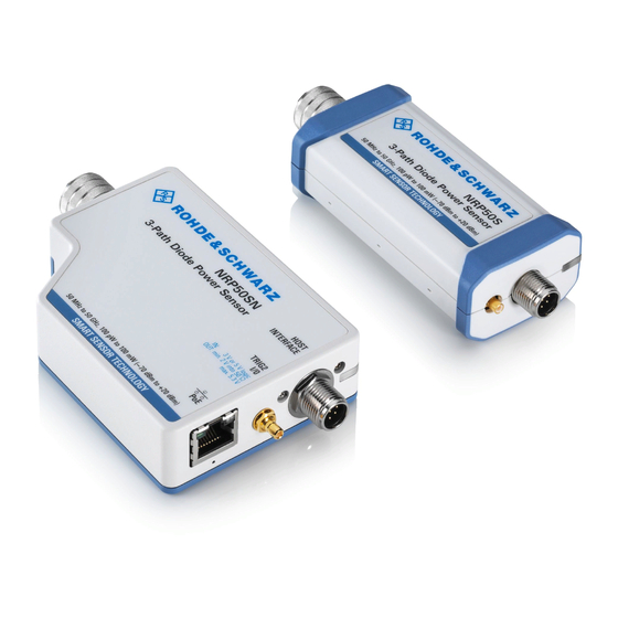
® Power Sensor Tour R&S NRPxxS(N) RF Connector 4 Power Sensor Tour This chapter provides an overview of the available connectors and LEDs of the power sensor. Figure 4-1, the USB power sensor is shown on the left, the LAN power sensor is shown on the right. -
Page 24: Trigger I/O Connector
® Power Sensor Tour R&S NRPxxS(N) Host Interface Table 4-1: R&S NRPxxS(N) RF connector characteristics Power sensor Male connector Matching female con- Tightening torque nector R&S NRP8S R&S NRP8SN 1.36 Nm (12'' lbs) R&S NRP18S R&S NRP18SN R&S NRP33S R&S NRP33SN 3.50 mm 3.50 mm/ 2.92 mm/ SMA R&S NRP33SN-V... -
Page 25: Status Led
® Power Sensor Tour R&S NRPxxS(N) LAN PoE Interface 4.4 Status LED The status LED gives information about the state of the power sensor. The following states are defined: Indication State White Idle state. The sensor performs no measurement and is ready for use. Flashing white Firmware update is in progress Slow flashing white... - Page 26 ® Power Sensor Tour R&S NRPxxS(N) LAN PoE Interface LAN reset button The LAN reset button is used for resetting the Ethernet connection parameters of the power sensor to their default values. Power over Ethernet status LED Available only for LAN power sensor. The power status LED shows whether the sensor is correctly powered over PoE or not.
-
Page 27: Operating Concepts
® Operating Concepts R&S NRPxxS(N) R&S NRP Toolkit 5 Operating Concepts For operating the power sensor, you can choose from various possibilities: ● Chapter 5.2, "Browser-Based User Interface", on page 30 ● Chapter 5.3, "Remote Control", on page 32 ● Chapter 5.4, "R&S NRPV", on page 32... - Page 28 ® Operating Concepts R&S NRPxxS(N) R&S NRP Toolkit Supported operating systems: ● Microsoft Windows versions – Microsoft Windows Vista 32/64-bit – Microsoft Windows 7 32/64-bit – Microsoft Windows 8/ 8.1 32/64-bit – Microsoft Windows 10 32/64-bit ● For information on other operating systems, see Chapter 5.1.1, "Versions and Downloads", on page 27.
- Page 29 ® Operating Concepts R&S NRPxxS(N) R&S NRP Toolkit 3. Accept the license terms to continue with the installation. 4. Click "Next" and complete the installation process. 5.1.3.1 Components of the R&S NRP Toolkit Access: "Start" > "NRP-Toolkit" The following tools are part of the R&S NRP Toolkit for Windows. Configure Network Sensor Useful if you have troubles establishing a LAN connection with an R&S NRP LAN power sensor.
-
Page 30: Browser-Based User Interface
® Operating Concepts R&S NRPxxS(N) Browser-Based User Interface NRP Version Display Displays version information of all installed, power measurement-relevant software packages. R&S NRP‑Z Uncertainty Calculator Determines the expanded measurement uncertainty. The tool comes with a manual (PDF) that is also available in the "Start" menu. S-Parameter Update Multi Helps loading an S-parameter table into the power sensor. - Page 31 ® Operating Concepts R&S NRPxxS(N) Browser-Based User Interface Setup HOST INTERFACE TRIG2 3 V or 5 V logic OUT: min. 2 V into 50 Ω max. 5.3 V SMART SENSOR TECHNOLOGY Ethernet Switch (PoE) Figure 5-1: Setup with the web user interface = Signal source = LAN power sensor = RJ-45 Ethernet connector...
-
Page 32: Remote Control
® Operating Concepts R&S NRPxxS(N) R&S NRPV The main dialog of the web user interface opens. 4. Select the "Continuous Average" tab and perform any necessary changes. 5. Press "Measurement > ON" to start the measurement. For a detailed description of the web user interface, refer to Chapter 6, "Browser- Based User Interface",... - Page 33 ® Operating Concepts R&S NRPxxS(N) R&S NRPV ● R&S NRP‑ZKU cable or an R&S NRP‑Z5 sensor hub and an R&S NRP‑ZK6 cable to connect the sensor to the computer ● Windows computer with installed: – R&S NRP Toolkit V 4.17 or higher –...
-
Page 34: R&S Power Viewer
® Operating Concepts R&S NRPxxS(N) R&S Power Viewer b) Select "Zero > Select > A" (channel short name). Zeroing takes several seconds. During zeroing, a message shows the pro- gress. After completion, the message reports either success or an error ("Suc- cess"... - Page 35 ® Operating Concepts R&S NRPxxS(N) R&S Power Viewer Required equipment ● R&S NRPxxS(N) power sensor ● R&S NRP‑ZKU cable or an R&S NRP‑Z5 sensor hub and an R&S NRP‑ZK6 cable to connect the sensor to the computer ● Computer with installed: –...
- Page 36 ® Operating Concepts R&S NRPxxS(N) R&S Power Viewer Note: Turn off all measurement power signals before zeroing. An active measure- ment signal during zeroing causes an error. a) Switch off the measurement signal. b) Select "Sensor > Zero (Signal off) ". 4.
-
Page 37: R&S Power Viewer Mobile
® Operating Concepts R&S NRPxxS(N) R&S NRX 5.6 R&S Power Viewer Mobile The R&S Power Viewer Mobile extends the functionality of the R&S Power Viewer to Android-based devices, such as a smartphone and tablets. You can download the R&S Power Viewer Mobile free of charge from the Google Play Store. -
Page 38: R&S Nrp2
® Operating Concepts R&S NRPxxS(N) R&S NRP2 Starting a measurement 1. Preset the R&S NRX and the connected R&S power sensors. a) Press the [Preset] key. b) Tap "Preset". All parameters are set to their defaults. 2. If measuring in zero-IF mode (RBW > 40 MHz), consider to zero the power sensor: Note: Turn off all measurement signals before zeroing. - Page 39 ® Operating Concepts R&S NRPxxS(N) R&S NRP2 Setup 3-Path Diode Power Sensor MHz to GHz, 100 pW to 200 mW (−70 dBm to +23 dBm) SMART SENSOR TECHNOLOGY Figure 5-5: Setup with an R&S NRP2 base unit 1 = Signal source 2 = R&S NRPxxS(N) power sensor 3 = Host interface connector 4 = R&S NRP‑ZK6 cable...
- Page 40 ® Operating Concepts R&S NRPxxS(N) R&S NRP2 b) Press the [ZERO] hardkey of the R&S NRP2. The "Zero" dialog box is displayed. c) Press the [ZERO] hardkey again to perform zeroing of all connected sensor channels ("Zero (All)") or press the appropriate softkey to select a specific sen- sor for zeroing.
-
Page 41: Browser-Based User Interface
® Browser-Based User Interface R&S NRPxxS(N) Main Dialog of the Web User Interface 6 Browser-Based User Interface The web user interface is an alternative way to operate an R&S NRPxxSN LAN power sensor. This chapter provides a description of the parameters used for setting a power mea- surement with the web user interface. -
Page 42: Setting The Unit
® Browser-Based User Interface R&S NRPxxS(N) Setting the Unit 6.2 Setting the Unit You can set the unit for the different parameters by typing the corresponding letter after the entered value. Figure 6-2: Parameter 1 = Parameter name 2 = Value 3 = Unit The following abbreviations are available: Unit... -
Page 43: Common Settings
® Browser-Based User Interface R&S NRPxxS(N) Common Settings Example: To change the representation of a "Trigger Level" of 100µW into dBm, enter -10dbm in the "Trigger Level" field. All future entries of solely numbers represent the value in dBm. If you enter -15 in the field, the "Trigger Level" value is set to -15.00 dBm. If you want to revert the value to Watt, enter 50uW. -
Page 44: Measurement Modes
® Browser-Based User Interface R&S NRPxxS(N) Measurement Modes <State> ← Offset Enables or disables the usage of the level offset. Remote command: on page 111 [SENSe<Sensor>:]CORRection:OFFSet:STATe <Value> ← Offset Adds a fixed level offset in dB to account for external losses. Remote command: on page 111 [SENSe<Sensor>:]CORRection:OFFSet... - Page 45 ® Browser-Based User Interface R&S NRPxxS(N) Measurement Modes Aperture Time Sets the aperture time, the width of the sampling windows. Remote command: on page 94 [SENSe<Sensor>:][POWer:][AVG:]APERture Duty Cycle Sets the duty cycle, the percentage of one period during which the signal is active, for pulse modulated signals.
- Page 46 ® Browser-Based User Interface R&S NRPxxS(N) Measurement Modes End Exclude Sets a time that is to be excluded at the end of the measurement period. Remote command: on page 109 [SENSe<Sensor>:]TIMing:EXCLude:STOP Trigger Level "Trigger Level" on page 54. Dropout Tolerance Sets the dropout time.
- Page 47 ® Browser-Based User Interface R&S NRPxxS(N) Measurement Modes Remote command: on page 98 [SENSe<Sensor>:][POWer:]TSLot[:AVG]:COUNt Nominal Width Sets the length of a timeslot in seconds. Remote command: on page 99 [SENSe<Sensor>:][POWer:]TSLot[:AVG]:WIDTh Start Exclude Sets a time that is to be excluded at the beginning of the measurement period. Remote command: on page 109 [SENSe<Sensor>:]TIMing:EXCLude:STARt...
-
Page 48: Settings
® Browser-Based User Interface R&S NRPxxS(N) Settings Trace Time........................48 Trace Offset Time......................48 Trace Points........................48 Trigger Source.......................48 Trigger Level......................... 48 Trigger Delay.........................48 Trace Time Sets the trace length. Remote command: on page 104 [SENSe<Sensor>:]TRACe:TIME Trace Offset Time Sets the relative position of the trigger event in relation to the beginning of the trace measurement sequence. - Page 49 ® Browser-Based User Interface R&S NRPxxS(N) Settings 6.5.1 Sensor Settings Describes the parameters for optimizing the measurement results for specific measure- ment requirements. Further information: ● Chapter 9.4.2, "Selecting a Measurement Path", on page 70 ● Chapter 9.8.4, "Configuring Corrections", on page 110 ●...
- Page 50 ® Browser-Based User Interface R&S NRPxxS(N) Settings A value of 0.0 corresponds to an ideal matched source. A value of 1.0 corresponds to total reflection. Remote command: on page 114 [SENSe<Sensor>:]SGAMma:MAGNitude Phase ← Γ Correction Sets the phase angle of the complex reflection coefficient of the source, Γ source Remote command: on page 115...
- Page 51 ® Browser-Based User Interface R&S NRPxxS(N) Settings Remote command: on page 127 TEST:SENSor? 6.5.2 Averaging Settings Describes the parameters for automatic averaging. Further information: ● Chapter 9.8.1, "Configuring Auto Averaging", on page 104 Access: main dialog of the web user interface > navigation pane > "Averaging" User Manual 1177.5079.02 ─...
- Page 52 ® Browser-Based User Interface R&S NRPxxS(N) Settings Averaging Mode......................52 └ <Mode>......................52 └ <Value>......................52 Filter Terminal Control....................52 Auto Measurement Time....................53 Averaging Mode Groups the averaging settings. See also Chapter 9.8.1, "Configuring Auto Averaging", on page 104. <Mode> ← Averaging Mode Sets the averaging mode.
- Page 53 ® Browser-Based User Interface R&S NRPxxS(N) Settings "Moving" Specifies that a measurement result is not output until the entire mea- surement has been completed. This means that the number of mea- surement cycle repetitions is equal to the set averaging factor. If the averaging factor is large, the measurement time can be very long.
- Page 54 ® Browser-Based User Interface R&S NRPxxS(N) Settings Trigger Source Groups the trigger source settings. <Source> ← Trigger Source Selects the trigger source. See Chapter 9.5.2.3, "Trigger Sources", on page 74. Remote command: on page 86 TRIGger:SOURce <Slope> ← Trigger Source Sets the polarity of the active slope of the trigger signal that is externally or internally applied.
- Page 55 ® Browser-Based User Interface R&S NRPxxS(N) Settings Remote command: on page 84 TRIGger:HYSTeresis 6.5.4 System Settings Describes the parameters of the general network environment and specific identifica- tion parameters of the power sensor in the network. Further information: ● Chapter 9.11, "Configuring the System", on page 128 Access: main dialog of the web user interface >...
- Page 56 ® Browser-Based User Interface R&S NRPxxS(N) Settings Gateway Sets the address of the default gateway, that means the router that is used to forward traffic to destinations beyond the local network. This router is on the same network as the instrument. Remote command: on page 130 SYSTem:COMMunicate:NETWork:IPADdress:GATeway...
-
Page 57: Firmware Update
® Firmware Update R&S NRPxxS(N) Updating the Firmware 7 Firmware Update ● Hardware and Software Requirements..............57 ● Updating the Firmware....................57 7.1 Hardware and Software Requirements For performing a firmware update, the system requirements are as follows: ● Connectors and cables for establishing a connection to the computer Chapter 3.5, "Connecting to a Computer", on page 13. -
Page 58: Using The Firmware Update For Nrp Family Program
® Firmware Update R&S NRPxxS(N) Updating the Firmware 7.2.1 Using the Firmware Update for NRP Family Program Firmware Update for NRP Family is part of the R&S NRP Toolkit. See also Chap- ter 5.1, "R&S NRP Toolkit", on page 27. Checking the prerequisites 1. - Page 59 ® Firmware Update R&S NRPxxS(N) Updating the Firmware Note: The "Hostname or IP Address" field is not used during this procedure. There- fore, leave it empty. 6. Under "Firmware", enter the full path and filename of the update file, or press the browse button next to the field.
-
Page 60: Using The Web User Interface
® Firmware Update R&S NRPxxS(N) Updating the Firmware 7.2.2 Using the Web User Interface 1. Connect the power sensor to the computer as described in Chapter 3.5, "Connect- ing to a Computer", on page 13. 2. Open the web user interface as described in Chapter 5.2, "Browser-Based User Interface", on page 30. - Page 61 ® Firmware Update R&S NRPxxS(N) Updating the Firmware Example: You want to update your R&S NRP18SN with the nrp18sn_FW_15.02.12.01.rsu file. This file has a size of 10242884 bytes. To send the file to the sensor for updating the firmware, your application has to assem- ble a memory block containing: SYST:FWUP <block_data>...
-
Page 62: Replacing An R&S Nrp-Zxx With An R&Snrpxxs(N)
® Replacing an R&S NRP-Zxx with an R&S NRPxxS(N) R&S NRPxxS(N) Prerequisites 8 Replacing an R&S NRP-Zxx with an R&S NRPxxS(N) The new R&S NRPxxS(N) sensors are compatible with the R&S NRP-Zxx series of power sensors. New power sensor Replaces this sensor R&S NRP8S/R&S NRP8SN - USB connected R&S NRP-Z11 R&S NRP18S/R&S NRP18SN - USB connected... - Page 63 ® Replacing an R&S NRP-Zxx with an R&S NRPxxS(N) R&S NRPxxS(N) Prerequisites After the new version of the R&S NRP Toolkit is installed, you can connect the R&S NRPxxS(N) power sensor to the computer and use it with Rohde & Schwarz software applications or your own programs.
-
Page 64: Remote Control Commands
® Remote Control Commands R&S NRPxxS(N) Notations 9 Remote Control Commands In the following sections, all commands implemented in the sensor are listed according to the command system and then described in detail. For the most part, the notation used complies with SCPI specifications. 9.1 Conventions Used in SCPI Command Descriptions Note the following conventions used in the remote command descriptions: ●... - Page 65 ® Remote Control Commands R&S NRPxxS(N) Notations Numeric suffixes <n> If a command can be applied to multiple instances of an object, e.g. specific sensors, the required instances can be specified by a suffix added to the command. Numeric suffixes are indicated by angular brackets (<1...4>, <n>, <I>) and are replaced by a single value in the command.
-
Page 66: Common Commands
® Remote Control Commands R&S NRPxxS(N) Common Commands Special characters | and { } A vertical bar in parameter definitions indicates alternative possibilities in the sense of "or". The effect of the command differs, depending on which parameter is used. Example: Definition: INITiate:CONTinuous ON | OFF Command INITiate:CONTinuous ON starts the measurements... -
Page 67: Ese
® Remote Control Commands R&S NRPxxS(N) Common Commands *ESE <register> Event Status Enable Sets the event status enable register to the specified value. The query returns the con- tents of the event status enable register in decimal form. Parameters: <register> Range: 0 to 255 *RST:... -
Page 68: Opt
® Remote Control Commands R&S NRPxxS(N) Common Commands *OPC? is preferred to because with *OPC?, the execution of commands can be *WAI queried from a controller program before new commands are sent. This prevents over- flow of the input queue when too many commands are sent that cannot be executed. Unlike *WAI, *OPC? must be sent at the end of a program message. -
Page 69: Sre
® Remote Control Commands R&S NRPxxS(N) Common Commands Stores the current device state under the specified number. The storage numbers 0 to 9 are available. Setting parameters: <number> Range: 0 to 9 *RST: Usage: Setting only *SRE <register> Service Request Enable Sets the service request enable register to the specified value. -
Page 70: Preparing For The Measurement
® Remote Control Commands R&S NRPxxS(N) Preparing for the Measurement Example: *TST? Query Response: Failed Usage: Query only *WAI WAIt to continue Prevents the execution of the subsequent commands until all preceding commands have been executed and all signals have settled. Usage: Event 9.4 Preparing for the Measurement... - Page 71 ® Remote Control Commands R&S NRPxxS(N) Preparing for the Measurement Remote commands: ....................71 [SENSe<Sensor>:]RANGe ..................71 [SENSe<Sensor>:]RANGe:AUTO ..................71 [SENSe<Sensor>:]RANGe:CLEVel [SENSe<Sensor>:]RANGe <range> Selects the active measurement path manually. Parameters: <range> The sensitivity of the paths differs. 0 is the most sensitive path. 2 is the most insensitive path.
-
Page 72: Controlling The Measurement
® Remote Control Commands R&S NRPxxS(N) Controlling the Measurement See also Chapter 9.7.1, "Continuous Average Measurement", on page 93. ● Burst average ("POWer:BURSt:AVG"): The integration time of a measurement is not predefined but determined by the sensor with the aid of a burst detector. The start of a burst is detected when the measurement signal rises above a set trigger level. - Page 73 ® Remote Control Commands R&S NRPxxS(N) Controlling the Measurement INITiate:ALL INITiate[:IMMediate] Starts a single measurement cycle. The sensor changes from the idle state to the wait- ing for trigger state. As soon as the trigger condition is fulfilled, the sensor begins the measurement.
- Page 74 ® Remote Control Commands R&S NRPxxS(N) Controlling the Measurement Further information: ● Chapter 9.5.5, "Configuring the Trigger", on page 81 9.5.2.1 Trigger States The power sensor has trigger states to define the exact start and stop time of a mea- surement and the sequence of a measurement cycle.
- Page 75 ® Remote Control Commands R&S NRPxxS(N) Controlling the Measurement Trigger source Description Remote commands to initiate the measurement "Internal" Uses the input signal as trigger signal. TRIGger:IMMediate "External 1" Uses the digital input signal supplied using a dif- TRIGger:IMMediate ferential pair in the 8-pin sensor cable. "External 2"...
- Page 76 ® Remote Control Commands R&S NRPxxS(N) Controlling the Measurement 9.5.3 Controlling the Measurement Results The R&S NRPxxS(N) can cope with the wide range of measurement scenarios with the help of the so-called "termination control". Depending on how fast your measurement results change, you can define, how the measurement results are output.
- Page 77 ® Remote Control Commands R&S NRPxxS(N) Controlling the Measurement 9.5.4.1 Continuous Average Mode General settings for these examples: ● INITiate:CONTinuous ● [SENSe<Sensor>:]AVERage:COUNt ● [SENSe<Sensor>:]AVERage:COUNt:AUTO Example: Repeating termination control Further settings for this example: ● [SENSe<Sensor>:]AVERage:TCONtrol REPeat The measurement is started by the trigger event. Due to the chopper phases, one measurement lasts twice the defined aperture time.
- Page 78 ® Remote Control Commands R&S NRPxxS(N) Controlling the Measurement Example: Moving termination control Further settings for this example: ● [SENSe<Sensor>:]AVERage:TCONtrol MOVing ● TRIGger:COUNt Every measurement is started by a trigger event. Due to the chopper phases, one measurement lasts twice the defined aperture time. During each measurement, the trigger synchronization is high (TRIGger:SYNC:STATe ON).
- Page 79 ® Remote Control Commands R&S NRPxxS(N) Controlling the Measurement Example: Repeating termination control Further settings for this example: ● [SENSe<Sensor>:]AVERage:TCONtrol REPeat Every chopper phase is started by a trigger event and lasts the defined aperture time. During a chopper phase, the trigger synchronization is high (TRIGger:SYNC:STATe ON).
- Page 80 ® Remote Control Commands R&S NRPxxS(N) Controlling the Measurement Example: Moving termination control Further settings for this example: ● [SENSe<Sensor>:]AVERage:TCONtrol MOVing Every chopper phase is started by a trigger event and lasts the defined aperture time. During a chopper phase, the trigger synchronization is high (TRIGger:SYNC:STATe ON).
- Page 81 ® Remote Control Commands R&S NRPxxS(N) Controlling the Measurement Example: Average count = 1 [SENSe<Sensor>:]AVERage:COUNt For average count 1, the setting of the termination control has no impact. In both cases, the measurement runs for the duration of one aperture time. Then, settled data are available, and the power sensor returns to the idle state.
-
Page 82: Trigger:atrigger:delay
® Remote Control Commands R&S NRPxxS(N) Controlling the Measurement TRIGger:ATRigger:DELay <delay> Effective only if is set to ON. TRIGger:ATRigger:STATe Sets the delay between the artificial trigger event and the beginning of the actual mea- surement Parameters: <delay> Range: 0.1 to 5.0 *RST: Default unit: Seconds TRIGger:ATRigger:EXECuted? -
Page 83: Trigger:delay
® Remote Control Commands R&S NRPxxS(N) Controlling the Measurement Example: Chapter 10.3, "Performing a Buffered Continuous Average Measurement", on page 146. TRIGger:DELay <delay> Sets the delay between the trigger event and the beginning of the actual measurement (integration). Parameters: <delay> Range: -5.0 to 10.0 *RST:... -
Page 84: Trigger:holdoff
® Remote Control Commands R&S NRPxxS(N) Controlling the Measurement Suffix: <2...2> Parameters: <impedance> HIGH | LOW HIGH ~10 kΩ 50 kΩ *RST: HIGH TRIGger:HOLDoff <holdoff> Sets the hold-off time, seeChapter 9.5.2.5, "Hold-Off Time", on page 75 . Parameters: <holdoff> Range: 0.00 to 10.00 *RST: 0.00... -
Page 85: Trigger:level
® Remote Control Commands R&S NRPxxS(N) Controlling the Measurement TRIGger:LEVel <level> Effective only if TRIGger:SOURce INTernal. Sets the trigger threshold for internal triggering derived from the test signal. If you enter a value without unit, the unit is defined by TRIGger:LEVel:UNIT. If an S-parameter device is active and/or if a mounted component with a global offset in front of the sensor is considered, the currently effective trigger threshold and a trig- ger threshold to be input are referenced to the appropriately shifted sensor data. -
Page 86: Trigger:master:state
® Remote Control Commands R&S NRPxxS(N) Controlling the Measurement TRIGger:MASTer:STATe <state> Enables or disables the trigger master mode of the sensor. In this state, the power sen- sor can output a digital trigger signal in sync with its own trigger event. If enabled, select the output port for the trigger signal using TRIGger:MASTer:PORT. -
Page 87: Configuring And Retrieving Results
® Remote Control Commands R&S NRPxxS(N) Configuring and Retrieving Results Parameters: <sync_port> EXT1 | EXTernal1 | EXT2 | EXTernal2 *RST: EXT1 TRIGger:SYNC:STATe <state> Usually used in combination with TRIGger:MASTer:STATe If enabled, blocks the external trigger bus as long as the sensor remains in the mea- surement state. - Page 88 ® Remote Control Commands R&S NRPxxS(N) Configuring and Retrieving Results ......................88 FORMat:BORDer ......................88 FORMat:SREGister ....................... 88 FORMat[:DATA] FORMat:BORDer <border> Selects the order of bytes in 32-bit or 64-bit binary data. Parameters: <border> NORMal | SWAPped NORMal The 1st byte is the least significant byte, the 4th/8th byte the most significant byte.
- Page 89 ® Remote Control Commands R&S NRPxxS(N) Configuring and Retrieving Results 32 | 64 32-bit or 64-bit If you omit the length, the R&S NRPxxS(N) sets the last used length. Example for REAL,32 format: #6768000..<binary float values>..Example for REAL,64 format: #71536000..<binary float values>..
- Page 90 ® Remote Control Commands R&S NRPxxS(N) Configuring and Retrieving Results "POWer:BURSt:AVG" Burst In remote control, this measurement mode is very similar to the ContAv mode. The integration time is, however, not predefined but determined by the sensor with the aid of a burst detector. The start of a burst is detected when the measurement signal rises above the set trigger level.
- Page 91 ® Remote Control Commands R&S NRPxxS(N) Configuring and Retrieving Results FETCh<Sensor>[:SCALar][:POWer]:BURSt? Queries the last valid measurement result for the burst average measurement mode. Usage: Query only FETCh<Sensor>[:SCALar][:POWer]:TSLot? Queries the last valid measurement result of the timeslot average measurement mode. Usage: Query only CALCulate:FEED <mode>...
-
Page 92: Configuring The Measurement Modes
® Remote Control Commands R&S NRPxxS(N) Configuring the Measurement Modes Example: The following sequence of commands configures a Peak Trace measurement *RST SENSe:FUNCtion "XTIMe:POWer" SENSe:FREQuency 1.0e9 SENSe:TRACe:POINts 500 SENS:TRAC:TIME 20e-3 TRIGger:SOURce INTernal TRIGger:SLOPe POSitive TRIGger:DTIMe 0.001 TRIGger:HYSTeresis 0.1 TRIGger:LEVel 30e-6 SENSe:TRACe:AVERage:COUNt 8 SENSe:TRACe:AVERage:STATe ON CALCulate:FEED "POWer:PEAK:TRACe"... - Page 93 ® Remote Control Commands R&S NRPxxS(N) Configuring the Measurement Modes ● Continuous Average Measurement.................93 ● Burst Average Measurement.................. 96 ● Timeslot Average Measurement................97 ● Trace Measurement....................99 9.7.1 Continuous Average Measurement The Continuous Average mode measures the signal average power asynchronously within definable time intervals (sampling windows).
- Page 94 ® Remote Control Commands R&S NRPxxS(N) Configuring the Measurement Modes Using ON, you can accelerate the mea- [SENSe<Sensor>:][POWer:][AVG:]FAST surement as follows: ● Chopper is deactivated. ● Average count is set to 1, no matter which average count you have set. Thus, the overall measurement time is only defined by the aperture time, and the mea- surement time for a fast measurement is calculated as follows: MT = APER...
- Page 95 ® Remote Control Commands R&S NRPxxS(N) Configuring the Measurement Modes [SENSe<Sensor>:][POWer:][AVG:]BUFFer:DATA? Queries the results of the continuous average result buffer and returns them even if the buffer is not full. In contrast the FETCh? command returns a result only if the buffer is full. Usage: Query only [SENSe<Sensor>:][POWer:][AVG:]BUFFer:SIZE <count>...
- Page 96 ® Remote Control Commands R&S NRPxxS(N) Configuring the Measurement Modes [SENSe<Sensor>:][POWer:][AVG:]SMOothing:STATe <state> Enables or disables the smoothing filter, a steep-edge digital lowpass filter. If you can- not adjust the aperture time exactly to the modulation period, the filter reduces result fluctuations caused by modulation.
- Page 97 ® Remote Control Commands R&S NRPxxS(N) Configuring the Measurement Modes [SENSe<Sensor>:]TIMing:EXCLude:STARt [SENSe<Sensor>:]TIMing: on page 109, see Chapter 9.8.3, "Setting Exclusion Time", EXCLude:STOP on page 109. Remote commands: ..............97 [SENSe<Sensor>:][POWer:]BURSt:DTOLerance ..............97 [SENSe<Sensor>:][POWer:]BURSt:LENGth? [SENSe<Sensor>:][POWer:]BURSt:DTOLerance <tolerance> Sets the drop-out tolerance, a time interval in which the pulse end is only recognized if the signal level no longer exceeds the trigger level (see Figure 9-2).
- Page 98 ® Remote Control Commands R&S NRPxxS(N) Configuring the Measurement Modes SENS:TSLOT:COUNT 3 T'Slot 1 T'Slot 2 T'Slot 3 Power Trigger event Trigger level Time SENS:TSLOT:MID:OFFS:TIME SENS:TSLOT:MID:TIME SENS:TSLOT:WIDTH Figure 9-3: Timeslot parameters Triggering a timeslot average measurement In the timeslot mode, internal and external trigger events from the signal are evaluated depending on the settings of the parameter.
- Page 99 ® Remote Control Commands R&S NRPxxS(N) Configuring the Measurement Modes Manual operation: "Number of Timeslots" on page 46 [SENSe<Sensor>:][POWer:]TSLot[:AVG]:WIDTh <width> Sets the length of the timeslot (see Figure 9-3). Parameters: <width> Range: 10.0e-6 to 0.10 *RST: 1.000e-3 Default unit: Seconds Manual operation: "Nominal Width"...
- Page 100 ® Remote Control Commands R&S NRPxxS(N) Configuring the Measurement Modes with a predefined size [SENSe<Sensor>:]TRACe:POINts. The length of an individ- ual measurement(-point) is determined from the ratio of measurement time and mea- surement points. The entire result is called a "trace". Each trace must be triggered sep- arately.
- Page 101 ® Remote Control Commands R&S NRPxxS(N) Configuring the Measurement Modes *RST: REPeat TRAC:AVER:TCON REP Example: [SENSe<Sensor>:]TRACe:AVERage[:STATe] <state> Switches the averaging filter on and off for the Trace mode. Parameters: <state> *RST: [SENSe<Sensor>:]TRACe:DATA? Returns the measured trace data in a well-defined format. Unlike the FETCh? command, [SENSe<Sensor>:]TRACe:DATA takes the settings of [SENSe<Sensor>:]AUXiliary into account, as explained below.
- Page 102 ® Remote Control Commands R&S NRPxxS(N) Configuring the Measurement Modes ● Content ('user data content'), see also Figure 9-5. As many bytes as 'LLLLL' speci- fied. ● Single linefeed character (symbolically shown as <LF>, Response format) Example The arbitrary block response data for a user data that contains 45182 bytes is: #545182xxxxxx..xxxxxx <LF>...
- Page 103 ® Remote Control Commands R&S NRPxxS(N) Configuring the Measurement Modes ● Measurement result values in the format that is described by the data type (cur- rently IEEE754 float only) If no measurands have been activated before exe- [SENSe<Sensor>:]AUXiliary cuting the measurement, the user data content is finished here. In case that auxiliary measurands have been selected, the above section is repeated for every auxiliary measurand.
-
Page 104: Configuring Basic Measurement Parameters
® Remote Control Commands R&S NRPxxS(N) Configuring Basic Measurement Parameters Parameters: <points> Range: 1 to 100000 *RST: Manual operation: "Trace Points" on page 48 [SENSe<Sensor>:]TRACe:REALtime <state> Available in trace mode. If disabled, each measurement from the power sensor is averaged. If enabled, only one sampling sequence per measurement is recorded, thus increasing the measure- ment speed. - Page 105 ® Remote Control Commands R&S NRPxxS(N) Configuring Basic Measurement Parameters ................105 [SENSe<Sensor>:]AVERage:COUNt ..............105 [SENSe<Sensor>:]AVERage:COUNt:AUTO ............106 [SENSe<Sensor>:]AVERage:COUNt:AUTO:MTIMe ............106 [SENSe<Sensor>:]AVERage:COUNt:AUTO:NSRatio .............106 [SENSe<Sensor>:]AVERage:COUNt:AUTO:RESolution ............106 [SENSe<Sensor>:]AVERage:COUNt:AUTO:SLOT .................107 [SENSe<Sensor>:]AVERage:RESet ............107 [SENSe<Sensor>:]AVERage:COUNt:AUTO:TYPE ................107 [SENSe<Sensor>:]AVERage:TCONtrol ................108 [SENSe<Sensor>:]AVERage[:STATe] [SENSe<Sensor>:]AVERage:COUNt <count> Sets the number of readings that are averaged for one measured value. The higher the count, the lower the noise, and the longer it takes to obtain a measured value.
- Page 106 ® Remote Control Commands R&S NRPxxS(N) Configuring Basic Measurement Parameters [SENSe<Sensor>:]AVERage:COUNt:AUTO:MTIMe <maximum_time> Sets an upper limit for the settling time of the auto-averaging filter if is set to NSRatio. Thus it limits [SENSe<Sensor>:]AVERage:COUNt:AUTO:TYPE the length of the filter. Parameters: <maximum_time> Range: 0.01 to 999.99 *RST:...
- Page 107 ® Remote Control Commands R&S NRPxxS(N) Configuring Basic Measurement Parameters Sets a timeslot from which the measured value is used to determine the filter length automatically. The timeslot number must not exceed the number of the currently set timeslots. Parameters: <slot>...
- Page 108 ® Remote Control Commands R&S NRPxxS(N) Configuring Basic Measurement Parameters See also Chapter 9.5, "Controlling the Measurement", on page 72. Parameters: <mode> MOVing | REPeat MOVing Outputs intermediate values to facilitate early detection of changes in the measured quantity. In the settled state, that means when the number of measurements specified by the average count has been performed, a moving average is output.
- Page 109 ® Remote Control Commands R&S NRPxxS(N) Configuring Basic Measurement Parameters Manual operation: "Frequency" on page 43 9.8.3 Setting Exclusion Time In the burst average and the timeslot average modes, you can define a time period at the beginning or at the end of an integration period, which is excluded from the mea- surement result, as shown in Figure 9-6.
- Page 110 ® Remote Control Commands R&S NRPxxS(N) Configuring Basic Measurement Parameters Parameters: <exclude_stop> Range: 0.0 to 1.0 *RST: Default unit: Seconds Manual operation: "End Exclude" on page 46 "End Exclude" on page 47 9.8.4 Configuring Corrections It is possible to set some parameters that compensate for a change of the measured signal due to fixed external influences.
- Page 111 ® Remote Control Commands R&S NRPxxS(N) Configuring Basic Measurement Parameters Manual operation: "Duty Cycle" on page 45 9.8.4.2 Offset Corrections The offset accounts for external losses by adding a fixed level offset in dB. The attenuation of an attenuator located ahead of the sensor (or the coupling attenua- tion of a directional coupler) is taken into account with a positive offset, i.e.
- Page 112 ® Remote Control Commands R&S NRPxxS(N) Configuring Basic Measurement Parameters All R&S NRPxxS(N) power sensors allow compensating for the influence of any 2-port device between the signal source and the sensor input. As a result, the firmware can calculate the power that the signal source actually delivers. Examples of such 2-port devices include attenuators, matching pads, minimum-loss pads and waveguide adapt- ers.
- Page 113 ® Remote Control Commands R&S NRPxxS(N) Configuring Basic Measurement Parameters [SENSe<Sensor>:]CORRection:SPDevice:LIST? Queries the list of the S-parameter data sets that have been loaded to the power sen- sor. The result of the query indicates the consecutive number and mnemonic of each data set.
- Page 114 ® Remote Control Commands R&S NRPxxS(N) Configuring Basic Measurement Parameters 3-Path Diode Power Sensor MHz to GHz, 100 pW to 200 mW (−70 dBm to +23 dBm) SMART SENSOR TECHNOLOGY Source Sensor Figure 9-8: Correction of interactions between the power sensor and the signal source If the gamma correction is performed in combination with an S-parameter correction ([SENSe<Sensor>:]CORRection:SPDevice:STATe ON), the following is taken into...
- Page 115 ® Remote Control Commands R&S NRPxxS(N) Configuring Basic Measurement Parameters Parameters: 0.0 ≙ ideal matched source <magnitude> 1.0 ≙ total reflection Range: 0.0 to 1.0 *RST: Manual operation: "Magnitude" on page 49 [SENSe<Sensor>:]SGAMma:PHASe <phase> Sets the phase angle of the complex reflection coefficient of the source, Γ source Parameters: <phase>...
-
Page 116: Menu Bar
® Remote Control Commands R&S NRPxxS(N) Configuring Basic Measurement Parameters User Interface of the S-Parameters Tool Figure 9-10: S-Parameters dialog Menu bar........................116 └ File........................ 116 └ Sensor......................117 └ Device......................117 └ Options......................117 └ User Data....................117 └ Remote....................117 └ Show Cal. -
Page 117: Sensor
® Remote Control Commands R&S NRPxxS(N) Configuring Basic Measurement Parameters Sensor ← Menu bar Provides options for loading and saving calibration data directly from or to the sensor, see: ● "To load a calibration data set from a power sensor" on page 119 ●... -
Page 118: Global Flags
® Remote Control Commands R&S NRPxxS(N) Configuring Basic Measurement Parameters Figure 9-11: Example Global Flags Groups the settings for the power sensor behavior regarding S-parameter corrections. S-Parameter Correction ON by Default ← Global Flags If this option is enabled, the S-parameter correction is activated automatically when the sensor is started. -
Page 119: Use Flags In Factory Cal. Data Set
® Remote Control Commands R&S NRPxxS(N) Configuring Basic Measurement Parameters Use Flags in Factory Cal. Data Set ← Global Flags Available if the power sensor supports two different calibration data sets: ● Factory calibration data set containing all factory calibration data. ●... - Page 120 ® Remote Control Commands R&S NRPxxS(N) Configuring Basic Measurement Parameters The "Upload Calibration Data" dialog opens. It shows a list of the available sen- sors. 3. If you cannot find your power sensor in the list, for example because of reconnect- ing the power sensor, you can reload the list by clicking "Rebuild List".
- Page 121 ® Remote Control Commands R&S NRPxxS(N) Configuring Basic Measurement Parameters 6. Create a backup of the calibration data set before making any changes. Select "File" > "Save Calibration Data". A dialog opens where you can select the location to save the calibration data. To change the S-parameter data 1.
- Page 122 ® Remote Control Commands R&S NRPxxS(N) Configuring Basic Measurement Parameters 4. If needed, load uncertainty data. See "To load an uncertainty parameter file" on page 122. 5. Check the entries in the "S-Parameter Device Mnemonic", "Lower Power Limit/W" and "Upper Power Limit/W" fields and change them, if necessary. For example, the lower and upper power limits are deduced from the power limits of the sensor itself and the minimum attenuation of the S-parameter device.
- Page 123 ® Remote Control Commands R&S NRPxxS(N) Configuring Basic Measurement Parameters To save the calibration data to the sensor 1. Select "Sensor" > "Save Calibration Data". The "Download Calibration Data" dialog opens. 2. Confirm that the correct power sensor is selected by clicking "Download". After a successful transfer of the data to the power sensor, a confirmation message is displayed.
- Page 124 ® Remote Control Commands R&S NRPxxS(N) Configuring Basic Measurement Parameters ● Option line The option line has the format #[<frequency unit>][<parameter>][<format>][<R n>], where: – Identifies the option line. – <frequency unit> Possible values are Hz, kHz, MHz or GHz. If a frequency unit is not specified, GHz is implicitly assumed.
-
Page 125: Calibrating/Zeroing The Power Sensor
® Remote Control Commands R&S NRPxxS(N) Calibrating/Zeroing the Power Sensor – <parameter> U must be specified for uncertainty data files. If a parameter is not specified, S is implicitly assumed and as a result an error message is triggered. – <format>... - Page 126 ® Remote Control Commands R&S NRPxxS(N) Calibrating/Zeroing the Power Sensor ......................126 CALibration:DATA .................... 126 CALibration:DATA:LENGth? ....................126 CALibration:USER:DATA .................. 126 CALibration:USER:DATA:LENGth? ................126 CALibration<Channel>:ZERO:AUTO CALibration:DATA <caldata> Writes a binary calibration data set in the memory of the sensor. Parameters: <caldata> <block_data>...
-
Page 127: Testing The Power Sensor
® Remote Control Commands R&S NRPxxS(N) Testing the Power Sensor After zero calibration, query the static error queue (SYSTem:SERRor?). The following responses are possible: ● No error, the zero calibration was successful. ● -240 Warning, zero calibration failed. See also the example. Suffix: <Channel>... -
Page 128: Configuring The System
® Remote Control Commands R&S NRPxxS(N) Configuring the System 9.11 Configuring the System The SYSTem subsystem contains a series of commands for general functions that do not directly affect the measurement. The SYSTem:COMMunicate:NETWork:... commands are only available for the R&S NRP LAN power sensors. Remote commands: .............. -
Page 129: System:communicate:network:restart
® Remote Control Commands R&S NRPxxS(N) Configuring the System .................... 139 SYSTem:TRANsaction:END ....................139 SYSTem[:SENSor]:NAME ......................140 SYSTem:VERSion? SYSTem:COMMunicate:NETWork:RESTart Effective only for the R&S NRP LAN power sensors. Restarts the network connection to the DUT, that means terminates the connection and sets it up again. -
Page 130: System:communicate:network:ipaddress
® Remote Control Commands R&S NRPxxS(N) Configuring the System In a LAN that uses a DNS server (domain name system server), you can access each connected instrument using a unique hostname instead of its IP address. The DNS server translates the hostname to the IP address. Using a hostname is especially use- ful if a DHCP server is used, as a new IP address can be assigned each time the instrument is restarted. -
Page 131: System:communicate:network:ipaddress:info
® Remote Control Commands R&S NRPxxS(N) Configuring the System Manual operation: "Gateway" on page 56 SYSTem:COMMunicate:NETWork:IPADdress:INFO? Effective only for the R&S NRP LAN power sensors. Queries the network status information. Usage: Query only SYSTem:COMMunicate:NETWork:IPADdress:MODE <mode> Effective only for the R&S NRP LAN power sensors. Sets whether the IP address is assigned automatically or manually. -
Page 132: System:error:all
® Remote Control Commands R&S NRPxxS(N) Configuring the System Suffix: <Channel> 1...4 Measurement channel if more than one channel is available. Usage: Query only SYSTem:ERRor:ALL? Queries all unread entries in the error/event queue and removes them from the queue. The response is a comma-separated list in first out order, each entry consisting of the error number and a short description of the error. -
Page 133: System:error[:Next]
® Remote Control Commands R&S NRPxxS(N) Configuring the System Example: SYST:ERR:COUN? Query Response: One error has occurred since the error queue was last read out. Usage: Query only SYSTem:ERRor[:NEXT]? Queries the error/event queue for the oldest entry and removes it from the queue. The response consists of an error number and a short description of the error. -
Page 134: System:help:headers
® Remote Control Commands R&S NRPxxS(N) Configuring the System While a firmware update is in progress, the LED of the sensor flashes in bright white color. When the firmware update is completed, you can read the result. The result of the query is a readable string. Example: SYST:FWUP:STAT? Query... - Page 135 ® Remote Control Commands R&S NRPxxS(N) Configuring the System Stock Number Serial SW Build MAC Address Hostname IP Address Domain Subnetmask Gateway Mode Status Sensor Name Technology Function MinPower MaxPower MinFreq MaxFreq Resolution Impedance Coupling Uptime Cal. Misc. Cal. Abs. Cal.
-
Page 136: System:initialize
® Remote Control Commands R&S NRPxxS(N) Configuring the System SYSTem:INITialize Sets the sensor to the standard state, i.e. the default settings for all test parameters are loaded in the same way as with *RST. The sensor then outputs a complete list of all supported commands and parameters. -
Page 137: System:minpower
® Remote Control Commands R&S NRPxxS(N) Configuring the System For more information, see SYSTem:LED:COLor. Parameters: <mode> USER | SENSor *RST: SENSor SYSTem:MINPower? Queries the lower power measurement limit. This value changes if is set to [SENSe<Sensor>:]CORRection:SPDevice:STATe ON. The lower measurement limit refers to the sensor or to the combination of a sensor and the components connected ahead of it. -
Page 138: System:restart
® Remote Control Commands R&S NRPxxS(N) Configuring the System SYSTem:RESTart Restarts the firmware of the R&S NRPxxS(N) . Usage: Event SYSTem:RUTime <update_time> Effective only in the NRP legacy mode. Sets the result update time. That is the maximum rate in which the power sensor can output measurement results. -
Page 139: System:serror:list[:Next]
® Remote Control Commands R&S NRPxxS(N) Configuring the System SYSTem:SERRor:LIST[:NEXT]? Queries the list of all static errors that have occurred but have already been resolved for the oldest entry and removes it from the queue. The response consists of an error number and a short description of the error. -
Page 140: Using The Status Register
® Remote Control Commands R&S NRPxxS(N) Using the Status Register The sensor name that you specify here is independent from the hostname of the sen- sor. However, if the sensor name is not specified, it defaults to the hostname. Example: SYST:NAME "InputModule-X5"... - Page 141 ® Remote Control Commands R&S NRPxxS(N) Using the Status Register 9.12.1 General Status Register Commands ......................141 STATus:PRESet ....................141 STATus:QUEue[:NEXT]? STATus:PRESet Resets the edge detectors and ENABle parts of all registers to a defined value. Usage: Event STATus:QUEue[:NEXT]? Queries the most recent error queue entry and deletes it. Positive error numbers indicate sensor specific errors.
- Page 142 ® Remote Control Commands R&S NRPxxS(N) Using the Status Register STATus:OPERation:LLFail[:SUMMary][:EVENt]? STATus:OPERation:MEASuring[:SUMMary][:EVENt]? STATus:OPERation:SENSe[:SUMMary][:EVENt]? STATus:OPERation:TRIGger[:SUMMary][:EVENt]? STATus:OPERation:ULFail[:SUMMary][:EVENt]? STATus:QUEStionable:CALibration[:SUMMary][:EVENt]? STATus:QUEStionable[:EVENt]? STATus:QUEStionable:POWer[:SUMMary][:EVENt]? STATus:QUEStionable:WINDow[:SUMMary][:EVENt]? Usage: Query only 9.12.4 Controlling the ENABle Part Further information: ● Chapter 11.3.2, "Structure of a SCPI Status Register", on page 163 STATus:DEVice:ENABle <value>...
- Page 143 ® Remote Control Commands R&S NRPxxS(N) Using the Status Register STATus:QUEStionable:POWer:NTRansition <value> STATus:QUEStionable:WINDow:NTRansition <value> Parameters: <value> *RST: 9.12.6 Controlling the Positive Transition Part Further information: ● Chapter 11.3.2, "Structure of a SCPI Status Register", on page 163 STATus:DEVice:PTRansition <value> STATus:OPERation:CALibrating:PTRansition <value> STATus:OPERation:PTRansition <value>...
-
Page 144: Performing Measurement Tasks - Programming Examples
® Performing Measurement Tasks - Programming Examples R&S NRPxxS(N) Performing the Fastest Measurement in Continuous Average Mode 10 Performing Measurement Tasks - Program- ming Examples If you install the optional software development kit (SDK) of the R&S NRP Toolkit, pro- gramming examples are provided. - Page 145 ® Performing Measurement Tasks - Programming Examples R&S NRPxxS(N) Performing the Fastest Measurement in Continuous Average Mode //Disable auto averaging SENSe:AVERage:COUNt:AUTO OFF //Enable the fast unchopped continuous average measurement SENSe:POWer:AVG:FAST ON //Set the buffer size and enable the buffer SENSe:BUFFer:SIZE 8192 SENSe:BUFFer:STATe ON //Set the data format to real FORMat:DATA REAL...
-
Page 146: Performing A Buffered Continuous Average Measurement
® Performing Measurement Tasks - Programming Examples R&S NRPxxS(N) Performing a Buffered Continuous Average Measurement SENSe:POWer:AVG:APERture 10e-6 //Disable the averaging filter SENSe:AVERage:STATE OFF //Set the buffer size and enable the buffer for continuous average results SENSe:BUFFer:SIZE 8192 SENSe:BUFFer:STAT ON //Initiate a continuous measurement INITiate:CONTinuous ON //Fetch the number of results that is currently stored //in the buffer after the measurement is done... - Page 147 ® Performing Measurement Tasks - Programming Examples R&S NRPxxS(N) Performing a Buffered Continuous Average Measurement // Auto-Trigger OFF SENSOR.write( "TRIG:ATR:STAT OFF" ); // Configure a buffered measurement // Buffer size is randomly selected to 17 SENSOR.write( "SENS:BUFF:SIZE 17" ); SENSOR.write( "SENS:BUFF:STAT ON" ); SENSOR.write( "TRIG:COUN 17"...
-
Page 148: Performing Trace Measurements
® Performing Measurement Tasks - Programming Examples R&S NRPxxS(N) Performing Trace Measurements // All 17 physical measurement have been executed. // That means, buffer is full and can be read SENSOR.query( "FETCH?", szBuf, sizeof( szBuf ) ); printf( szBuf ); 10.4 Performing Trace Measurements *RST //Set the sensor's operation mode to trace... -
Page 149: Trace Measurement With Synchronization To Measurement Complete
® Performing Measurement Tasks - Programming Examples R&S NRPxxS(N) Trace Measurement with Synchronization to Measurement Complete //Query the measurement results FETCh? 10.5 Trace Measurement with Synchronization to Measure- ment Complete This example, written in pseudo code, shows how to setup and execute a trace mea- surement using a non-blocking technique. - Page 150 ® Performing Measurement Tasks - Programming Examples R&S NRPxxS(N) Trace Measurement with Synchronization to Measurement Complete bool bMeasReady = false; // poll until measurement is ready... // (this loop could also check for cancel-requests from the user or other break conditions) while ( ! bMeasReady ) query( "STAT:OPER:MEAS:EVEN?", &iEvent );...
-
Page 151: Remote Control Basics
® Remote Control Basics R&S NRPxxS(N) Remote Control Interfaces and Protocols 11 Remote Control Basics ● Remote Control Interfaces and Protocols............. 151 ● SCPI Command Structure..................155 ● Status Reporting System..................162 11.1 Remote Control Interfaces and Protocols For remote control, communication between the R&S NRPxxS(N) power sensors and the controlling host is established based on various interfaces and protocols. - Page 152 ® Remote Control Basics R&S NRPxxS(N) Remote Control Interfaces and Protocols Besides USBTMC, the NRP legacy protocol is available to ensure the compatibility of the R&S NRPxxS(N) power sensors with the R&S NRP‑Z series of power sensors. The usage of this protocol is not recommended for new applications. The resource string represents an addressing scheme that is used to establish a com- munication session with the sensor.
- Page 153 ® Remote Control Basics R&S NRPxxS(N) Remote Control Interfaces and Protocols For remote control via a network, the computer and the power sensor must be connec- ted via the Ethernet interface to a common network with TCP/IP network protocol. The TCP/IP network protocol and the associated network services are preconfigured on the power sensor.
- Page 154 ® Remote Control Basics R&S NRPxxS(N) Remote Control Interfaces and Protocols Socket Communication TCPIP::<IP address or hostname>::port::SOCKET ● port determines the used port number ● SOCKET indicates the raw network socket resource class Socket communication requires the specification of the port (commonly referred to as port number) and of "SOCKET"...
-
Page 155: Scpi Command Structure
® Remote Control Basics R&S NRPxxS(N) SCPI Command Structure ● Supports simultaneous access of multiple users by providing versatile locking mechanisms ● Usable for IPv6 or IPv4 networks The HiSLIP data is sent to the device using the "fire and forget" method with immediate return. - Page 156 ® Remote Control Basics R&S NRPxxS(N) SCPI Command Structure 11.2.1 Syntax for Common Commands Common (=device-independent) commands consist of a header preceded by an aster- isk (*) and possibly one or more parameters. Examples: *RST RESET Resets the instrument. *ESE EVENT STATUS ENABLE Sets the bits of the event status enable registers.
- Page 157 ® Remote Control Basics R&S NRPxxS(N) SCPI Command Structure Optional mnemonics Some command systems permit certain mnemonics to be inserted into the header or omitted. These mnemonics are marked by square brackets in the description. The instrument must recognize the long command to comply with the SCPI standard. Some commands are considerably shortened by these optional mnemonics.
- Page 158 ® Remote Control Basics R&S NRPxxS(N) SCPI Command Structure Numeric values Numeric values can be entered in any form, i.e. with sign, decimal point and exponent. Values exceeding the resolution of the instrument are rounded up or down. The man- tissa can comprise up to 255 characters, the exponent must lie inside the value range -32000 to 32000.
- Page 159 ® Remote Control Basics R&S NRPxxS(N) SCPI Command Structure Boolean Parameters Boolean parameters represent two states. The "ON" state (logically true) is represen- ted by "ON" or a numeric value 1. The "OFF" state (logically untrue) is represented by "OFF" or the numeric value 0. The numeric values are provided as the response for a query.
- Page 160 ® Remote Control Basics R&S NRPxxS(N) SCPI Command Structure Example: SYSTem:HELP:SYNTax:ALL? Response: #45168xxxxxxxx The ASCII character # introduces the data block. The next number indicates how many of the following digits describe the length of the data block. In the example, the 4 fol- lowing digits indicate the length to be 5168 bytes.
- Page 161 ® Remote Control Basics R&S NRPxxS(N) SCPI Command Structure Several commands in a command line must be separated by a semicolon ";". If the next command belongs to a different command system, the semicolon is followed by a colon. If the successive commands belong to the same system, having one or several levels in common, the command line can be abbreviated.
-
Page 162: Status Reporting System
® Remote Control Basics R&S NRPxxS(N) Status Reporting System Response: INT 11.3 Status Reporting System The status reporting system stores all information on the current operating state of the power sensor, and on errors which have occurred. This information is stored in the sta- tus registers and in the error queue. - Page 163 ® Remote Control Basics R&S NRPxxS(N) Status Reporting System The highest level is formed by the status byte register (STB) and the associated ser- vice request enable (SRE) register. The status byte register (STB) receives its information from: ● Standard event status register (ESR) ●...
- Page 164 ® Remote Control Basics R&S NRPxxS(N) Status Reporting System The Positive TRansition part acts as a transition filter. When a bit of the CONDition part is changed from 0 to 1, the associated PTR bit decides whether the EVENt bit is set to 1.
- Page 165 ® Remote Control Basics R&S NRPxxS(N) Status Reporting System ble with the CONDition register of a SCPI defined register and is at the highest level of the SCPI hierarchy. Its special feature is that bit 6 acts as the summary bit of all other bits of the status byte register.
- Page 166 ® Remote Control Basics R&S NRPxxS(N) Status Reporting System Bit No. Meaning MSS: Master status summary bit This bit is set if the sensor triggers a service request. This happens if one of the other bits of this register is set together with its enable bit in the service request enable register (SRE).
- Page 167 ® Remote Control Basics R&S NRPxxS(N) Status Reporting System Querying the register: ● STATus:DEVice:CONDition? ● STATus:DEVice[:EVENt]? Querying the static errors: ● SYSTem:SERRor? Table 11-5: Meaning of bits used in the device status register Bit No. Meaning Sum of SERR bits The sum/combination of SERR bits 1 to 4.
- Page 168 ® Remote Control Basics R&S NRPxxS(N) Status Reporting System 11.3.6 Questionable Status Register Contains information on questionable sensor states. Such states occur when the sen- sor is not operated in compliance with its specifications. Questionable Status Power Summary Calibration Summary POST Failure Querying the register: ●...
- Page 169 ® Remote Control Basics R&S NRPxxS(N) Status Reporting System 11.3.6.1 Questionable Power Status Register The CONDition register contains information whether the measured power values are questionable. Querying the register: ● STATus:QUEStionable:POWer:CONDition? ● STATus:QUEStionable:POWer[:SUMMary][:EVENt]? Table 11-7: Meaning of bits used in the questionable power status register Bit No.
- Page 170 ® Remote Control Basics R&S NRPxxS(N) Status Reporting System Standard Operation Complete Event Status Query Error Device-Dependent Error Execution Error Command Error User Request Power On Table 11-9: Meaning of bits used in the standard event status register Bit No. Meaning Operation complete When the *OPC command is received, this bit is set if all previous commands have been...
- Page 171 ® Remote Control Basics R&S NRPxxS(N) Status Reporting System Operation Calibrating Status Measuring Triggering Sense Summary Lower Limit Fail Upper Limit Fail Querying the register: ● STATus:OPERation:CONDition? ● STATus:OPERation[:EVENt]? Table 11-10: Meaning of bits used in the operation status register Bit No.
- Page 172 ® Remote Control Basics R&S NRPxxS(N) Status Reporting System Bit No. Meaning Lower limit fail status register This bit is set if a displayed value has dropped below a lower limit value. Chapter 11.3.8.5, "Operation Lower Limit Fail Status Register", on page 174.
- Page 173 ® Remote Control Basics R&S NRPxxS(N) Status Reporting System Table 11-12: Meaning of bits used in the operation measuring status register Bit No. Meaning Not used Sensor measuring The sensor is performing a measurement. 5 to 15 Not used 11.3.8.3 Operation Trigger Status Register The CONDition register contains information about whether a sensor is in the waiting for trigger state, i.e.
- Page 174 ® Remote Control Basics R&S NRPxxS(N) Status Reporting System Table 11-14: Meaning of bits used in the operation sense status register Bit No. Meaning Not used Sensor initializing The sensor is being initialized. 5 to 15 Not used 11.3.8.5 Operation Lower Limit Fail Status Register The CONDition register contains information about whether a displayed value is below a configured lower limit.
-
Page 175: Troubleshooting
® Troubleshooting R&S NRPxxS(N) Performing a Selftest 12 Troubleshooting ● Displaying Status Information................175 ● Performing a Selftest.....................175 ● Problems during a Firmware Update..............176 ● Cannot Establish a LAN Connection..............176 12.1 Displaying Status Information Status information is available in several ways. Status LED of the R&S NRPxxS(N) The position of the status LED is indicated in Chapter 4, "Power Sensor... -
Page 176: Problems During A Firmware Update
® Troubleshooting R&S NRPxxS(N) Cannot Establish a LAN Connection 12.3 Problems during a Firmware Update The firmware update is described in Chapter 7, "Firmware Update", on page 57. Solutions for potential problems that can occur when using the Firmware Update for NRP Family, see "Troubleshooting"... -
Page 177: List Of Commands
® List of Commands R&S NRPxxS(N) List of Commands [SENSe<Sensor>:][POWer:][AVG:]APERture....................94 [SENSe<Sensor>:][POWer:][AVG:]BUFFer:CLEar..................94 [SENSe<Sensor>:][POWer:][AVG:]BUFFer:COUNt?..................94 [SENSe<Sensor>:][POWer:][AVG:]BUFFer:DATA?..................95 [SENSe<Sensor>:][POWer:][AVG:]BUFFer:SIZE....................95 [SENSe<Sensor>:][POWer:][AVG:]BUFFer:STATe..................95 [SENSe<Sensor>:][POWer:][AVG:]FAST......................95 [SENSe<Sensor>:][POWer:][AVG:]SMOothing:STATe..................96 [SENSe<Sensor>:][POWer:]BURSt:DTOLerance................... 97 [SENSe<Sensor>:][POWer:]BURSt:LENGth?....................97 [SENSe<Sensor>:][POWer:]TSLot[:AVG]:COUNt................... 98 [SENSe<Sensor>:][POWer:]TSLot[:AVG]:WIDTh....................99 [SENSe<Sensor>:][POWer:]TSLot[:AVG][:EXCLude]:MID:OFFSet[:TIME].............99 [SENSe<Sensor>:][POWer:]TSLot[:AVG][:EXCLude]:MID:TIME..............99 [SENSe<Sensor>:][POWer:]TSLot[:AVG][:EXCLude]:MID[:STATe]..............99 [SENSe<Sensor>:]AUXiliary..........................92 [SENSe<Sensor>:]AVERage:COUNt......................105 [SENSe<Sensor>:]AVERage:COUNt:AUTO....................105 [SENSe<Sensor>:]AVERage:COUNt:AUTO:MTIMe..................106 [SENSe<Sensor>:]AVERage:COUNt:AUTO:NSRatio................... 106 [SENSe<Sensor>:]AVERage:COUNt:AUTO:RESolution................ - Page 178 ® List of Commands R&S NRPxxS(N) [SENSe<Sensor>:]TRACe:DATA?.........................101 [SENSe<Sensor>:]TRACe:MPWidth?......................103 [SENSe<Sensor>:]TRACe:OFFSet:TIME......................103 [SENSe<Sensor>:]TRACe:POINts........................ 103 [SENSe<Sensor>:]TRACe:REALtime......................104 [SENSe<Sensor>:]TRACe:TIME........................104 *CLS.................................66 *ESE................................67 *ESR?................................67 *IDN?................................67 *IST?................................67 *OPC................................67 *OPT?................................68 *PRE................................68 *RCL................................68 *RST................................68 *SAV.................................68 *SRE................................69 *STB?................................69 *TRG................................69 *TST?................................69 *WAI.................................70 ABORt................................72 CALCulate:FEED.............................91 CALibration:DATA............................
- Page 179 ® List of Commands R&S NRPxxS(N) STATus:OPERation:ENABle.......................... 142 STATus:OPERation:LLFail:CONDition?......................141 STATus:OPERation:LLFail:ENABle....................... 142 STATus:OPERation:LLFail:NTRansition......................142 STATus:OPERation:LLFail:PTRansition......................143 STATus:OPERation:LLFail[:SUMMary][:EVENt]?..................142 STATus:OPERation:MEASuring:CONDition?....................141 STATus:OPERation:MEASuring:ENABle.......................142 STATus:OPERation:MEASuring:NTRansition....................142 STATus:OPERation:MEASuring:PTRansition....................143 STATus:OPERation:MEASuring[:SUMMary][:EVENt]?..................142 STATus:OPERation:NTRansition........................142 STATus:OPERation:PTRansition........................143 STATus:OPERation:SENSe:CONDition?.......................141 STATus:OPERation:SENSe:ENABle......................142 STATus:OPERation:SENSe:NTRansition...................... 142 STATus:OPERation:SENSe:PTRansition...................... 143 STATus:OPERation:SENSe[:SUMMary][:EVENt]?..................142 STATus:OPERation:TRIGger:CONDition?.....................141 STATus:OPERation:TRIGger:ENABle......................142 STATus:OPERation:TRIGger:NTRansition....................142 STATus:OPERation:TRIGger:PTRansition....................
- Page 180 ® List of Commands R&S NRPxxS(N) STATus:QUEue[:NEXT]?..........................141 SYSTem:COMMunicate:NETWork:IPADdress....................130 SYSTem:COMMunicate:NETWork:IPADdress:GATeway................130 SYSTem:COMMunicate:NETWork:IPADdress:INFO?...................131 SYSTem:COMMunicate:NETWork:IPADdress:MODE...................131 SYSTem:COMMunicate:NETWork:IPADdress:SUBNet:MASK..............131 SYSTem:COMMunicate:NETWork:RESet..................... 129 SYSTem:COMMunicate:NETWork:RESTart....................129 SYSTem:COMMunicate:NETWork:STATus?....................129 SYSTem:COMMunicate:NETWork[:COMMon]:DOMain................129 SYSTem:COMMunicate:NETWork[:COMMon]:HOSTname................129 SYSTem:DFPRint<Channel>?........................131 SYSTem:ERRor:ALL?............................132 SYSTem:ERRor:CODE:ALL?........................132 SYSTem:ERRor:CODE[:NEXT]?........................132 SYSTem:ERRor:COUNt?..........................132 SYSTem:ERRor[:NEXT]?..........................133 SYSTem:FWUPdate............................133 SYSTem:FWUPdate:STATus?........................133 SYSTem:HELP:HEADers?..........................134 SYSTem:HELP:SYNTax:ALL?........................134 SYSTem:HELP:SYNTax?..........................134 SYSTem:INFO?.............................
- Page 181 ® List of Commands R&S NRPxxS(N) TRIGger:DTIMe............................... 83 TRIGger:EXTernal<2...2>:IMPedance......................83 TRIGger:HOLDoff............................84 TRIGger:HYSTeresis............................84 TRIGger:IMMediate............................84 TRIGger:LEVel..............................85 TRIGger:LEVel:UNIT............................85 TRIGger:MASTer:PORT..........................85 TRIGger:MASTer:STATe..........................86 TRIGger:SLOPe...............................86 TRIGger:SOURce............................86 TRIGger:SYNC:PORT............................. 86 TRIGger:SYNC:STATe.............................87 UNIT:POWer..............................87 User Manual 1177.5079.02 ─ 10...
-
Page 182: Index
® Index R&S NRPxxS(N) Index Android device Electromagnetic interference (EMI) ........12 R&S Power Viewer Mobile .......... 37 Electrostatic discharge (ESD) ........... 12 Application cards ..............8 ENABle ................164 Application notes ..............8 Ethernet interface Remote control ............152 EVENt ................164 Basic measurement parameters Remote control commands ........ - Page 183 ® Index R&S NRPxxS(N) Mnemonics ..............155 VISA resource strings ..........153 Mobile measurements ............37 VXI-11 protocol ............154 Remote control commands Basic measurement parameters ....... 104 Resource string Network status LED ............26 HiSLIP ............... 153 NTRansition ..............163 Socket ...............
- Page 184 ® Index R&S NRPxxS(N) USB interface Remote control ............151 USB product ID ............... 152 USB resource string ............152 USB sensor hub ..............15 User manual ................ 7 Versions of R&S NRP software ......... 30 VISA Resource string ............153 VXI-11 Protocol ..............
Need help?
Do you have a question about the NRPxxS Series and is the answer not in the manual?
Questions and answers