Table of Contents
Advertisement
Quick Links
Advertisement
Chapters
Table of Contents

Related Manuals for R&S NRP Series


Summary of Contents for R&S NRP Series
- Page 1 ® R&S NRPxxA(N) Average Power Sensors User Manual (;ÛÊA2) 1177601702 Version 08...
- Page 2 This manual describes the following average power sensors with firmware version FW 02.30 and later: ● ® R&S NRP6A (1424.6796K02) ● ® R&S NRP6AN (1424.6809K02) ● ® R&S NRP18A (1424.6815K02) ● ® R&S NRP18AN (1424.6821K02) © 2022 Rohde & Schwarz GmbH & Co. KG Muehldorfstr.
-
Page 3: Table Of Contents
® Contents R&S NRPxxA(N) Contents 1 Safety and regulatory information............9 Safety instructions......................9 Labels on the product....................10 Warning messages in the documentation..............10 2 Welcome....................11 Documentation overview....................11 2.1.1 Getting started manual....................11 2.1.2 User manuals........................ 11 2.1.3 Tutorials.........................11 2.1.4 Instrument security procedures..................11 2.1.5 Basic safety instructions.................... - Page 4 ® Contents R&S NRPxxA(N) Trigger I/O connector....................28 LAN PoE interface.......................28 5 Operating concepts................29 R&S NRP Toolkit......................29 5.1.1 Versions and downloads....................29 5.1.2 System requirements....................29 5.1.3 R&S NRP Toolkit for Windows..................30 Browser-based user interface..................32 Remote control......................34 R&S NRPV........................34 R&S Power Viewer......................
- Page 5 ® Contents R&S NRPxxA(N) Prerequisites....................... 57 9 Remote control commands..............58 Conventions used in SCPI command descriptions..........58 Notations........................59 Common commands....................60 Preparing for the measurement.................64 9.4.1 Selecting the reference source..................64 9.4.2 Selecting a measurement path..................64 9.4.3 Selecting a measurement mode................... 65 9.4.4 Configuring the measured values.................
- Page 6 ® Contents R&S NRPxxA(N) 9.13.2 Reading the CONDition part..................121 9.13.3 Reading the EVENt part....................122 9.13.4 Controlling the ENABle part..................122 9.13.5 Controlling the negative transition part................122 9.13.6 Controlling the positive transition part................. 123 10 Performing measurement tasks - programming examples....124 10.1 Performing the simplest measurement..............124 10.2...
- Page 7 ® Contents R&S NRPxxA(N) 14.4 Disposal........................153 List of commands................155 Index....................159 User Manual 1177.6017.02 ─ 08...
- Page 8 ® Contents R&S NRPxxA(N) User Manual 1177.6017.02 ─ 08...
-
Page 9: Safety And Regulatory Information
® Safety and regulatory information R&S NRPxxA(N) Safety instructions 1 Safety and regulatory information The product documentation helps you use the product safely and efficiently. Follow the instructions provided here and in the following chapters. Intended use The power sensors are intended for accurate and uncomplicated power measurements in production, R&D and calibration labs as well as for installation and maintenance tasks. -
Page 10: Labels On The Product
® Safety and regulatory information R&S NRPxxA(N) Warning messages in the documentation Choosing the operating site Only use the product indoors. The product casing is not waterproof. Observe the ambient conditions such as altitude, operating temperature and climatic loads; see the data sheet. Meaning of safety labels Safety labels on the product warn against potential hazards. -
Page 11: Welcome
® Welcome R&S NRPxxA(N) Documentation overview 2 Welcome This chapter provides an overview of the user documentation and an introduction to the R&S NRPxxA(N). 2.1 Documentation overview This section provides an overview of the R&S NRPxxA(N) user documentation. Unless specified otherwise, you find the documents on the R&S NRPxxA(N) product page at: www.rohde-schwarz.com/product/nrp-a-an 2.1.1 Getting started manual Introduces the R&S NRPxxA(N) and describes how to set up and start working with the... -
Page 12: Data Sheets And Brochures
These documents deal with special applications or background information on particu- lar topics. 2.2 Key features The average power sensors are members of the R&S NRP series power sensors from Rohde & Schwarz. They provide a high-speed USB interface that constitutes both the communication port and the power supply connection. -
Page 13: Preparing For Use
® Preparing for use R&S NRPxxA(N) Choosing the operating site 3 Preparing for use Here, you can find basic information about setting up the product for the first time. ● Unpacking and checking..................13 ● Choosing the operating site..................13 ● Considerations for test setup.................. -
Page 14: Considerations For Test Setup
® Preparing for use R&S NRPxxA(N) Connecting to a DUT 3.3 Considerations for test setup Give particular attention to the following aspects when handling power sensors. EMI impact on measurement results Electromagnetic interference (EMI) can affect the measurement results. To suppress electromagnetic radiation during operation: ●... -
Page 15: Powering The Power Sensor
® Preparing for use R&S NRPxxA(N) Powering the power sensor 3-Path Diode Power Sensor MHz to GHz, 100 pW to 200 mW (−70 dBm to +23 dBm) SMART SENSOR TECHNOLOGY 4. NOTICE! Risk of damaging the center pin of the RF connector. Only rotate the hex nut of the RF connector. -
Page 16: Connecting A Cable To The Host Interface
® Preparing for use R&S NRPxxA(N) Connecting to a controlling host 3.6 Connecting a cable to the host interface For connecting the power sensor to a USB host, use the host interface. See Chap- ter 4.3, "Host interface", on page 27. Depending on the USB host, use one of the following cables: ●... - Page 17 ® Preparing for use R&S NRPxxA(N) Connecting to a controlling host Chapter 3.7.3, "Using a LAN connection", on page 20. 3.7.1.1 Simple USB connection All R&S NRPxxA(N) power sensors can be connected to the USB interface of a com- puter. Required equipment ●...
- Page 18 ® Preparing for use R&S NRPxxA(N) Connecting to a controlling host 3.7.1.2 R&S NRP‑Z5 sensor hub setup The R&S NRP‑Z5 sensor hub (high-speed USB 2.0) can host up to four R&S NRPxxA(N) power sensors and provides simultaneous external triggering to all con- nected sensors.
-
Page 19: Base Unit
® Preparing for use R&S NRPxxA(N) Connecting to a controlling host Set up as shown in Figure 3-2. 1. Connect the R&S NRP‑ZK6 cable to the power sensor. See "To connect a cable to the host interface of the power sensor" on page 16. -
Page 20: Using A Lan Connection
® Preparing for use R&S NRPxxA(N) Connecting to a controlling host 3.7.3 Using a LAN connection Requires a power sensor with networking capabilities, a LAN power sensor. 3.7.3.1 Connecting a LAN power sensor to the LAN Depending on the available equipment, you can choose from different ways to connect a LAN power sensor to a controlling host. - Page 21 ® Preparing for use R&S NRPxxA(N) Connecting to a controlling host Connect the RJ-45 Ethernet connector of the sensor to an Ethernet switch that supports PoE power delivery. 3. Connect the controlling host to the Ethernet switch. 4. Establish a connection between the power sensor and the network. Chapter 3.7.3.2, "Establishing a connection to the network", on page 22.
- Page 22 ® Preparing for use R&S NRPxxA(N) Connecting to a controlling host Chapter 3.7.3.2, "Establishing a connection to the network", on page 22. Setup with a PoE injector HOST INTERFACE TRIG2 3 V or 5 V logic OUT: min. 2 V into 50 Ω...
- Page 23 ® Preparing for use R&S NRPxxA(N) Connecting to a controlling host In both cases, you can address the LAN power sensor as follows: ● Chapter 3.7.3.3, "Using hostnames", on page 23 ● Chapter 3.7.3.4, "Assigning the IP address", on page 24 To set up a network Ethernet connection 1.
- Page 24 ® Preparing for use R&S NRPxxA(N) Connecting to a controlling host Default hostname The default hostname follows the syntax: <device name>-<serial number>, where: ● <device name> is the short name of your sensor. For example, the <device name> of R&S NRP18AN is nrp6an. ●...
- Page 25 ® Preparing for use R&S NRPxxA(N) Connecting to a controlling host ● If the network does not support DHCP, the LAN power sensor tries to obtain the IP address via the zeroconf (APIA) protocol. If this attempt does not succeed or if the instrument is set to using alternate TCP/IP configuration, the IP address must be set manually.
-
Page 26: Power Sensor Tour
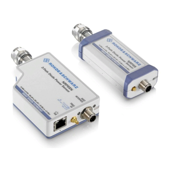
Figure 4-1, the USB power sensor is shown on the left, the LAN power sensor is shown on the right. Figure 4-1: R&S NRP series power sensors (example) 1 = RF connector, see Chapter 4.1, "RF connector", on page 26 2 = Status LED, see Chapter 4.2, "Status... -
Page 27: Status Information
® Power sensor tour R&S NRPxxA(N) Host interface Table 4-1: R&S NRPxxA(N) RF connector characteristics Power sensor Male connector Matching female con- Tightening torque nector R&S NRP6A R&S NRP6AN 1.36 Nm (12'' lbs) R&S NRP18A R&S NRP18AN 4.2 Status information The status LED gives information about the state of the power sensor. -
Page 28: Trigger I/O Connector
® Power sensor tour R&S NRPxxA(N) LAN PoE interface 4.4 Trigger I/O connector The trigger I/O is a connector of SMB type. It is used as an input for signals if the trigger source parameter is set to EXTernal2. It is used as an output for trigger signals if the sensor is operated in the trigger sender mode. -
Page 29: Operating Concepts
® Operating concepts R&S NRPxxA(N) R&S NRP Toolkit 5 Operating concepts For operating the power sensor, you can choose from various possibilities: ● Chapter 5.2, "Browser-based user interface", on page 32 ● Chapter 5.3, "Remote control", on page 34 ● Chapter 5.4, "R&S NRPV", on page 34... -
Page 30: R&S Nrp Toolkit For Windows
® Operating concepts R&S NRPxxA(N) R&S NRP Toolkit Supported Microsoft Windows versions: ● Microsoft Windows Vista 32/64-bit ● Microsoft Windows 7 32/64-bit ● Microsoft Windows 8/ 8.1 32/64-bit ● Microsoft Windows 10 32/64-bit 5.1.3 R&S NRP Toolkit for Windows The R&S NRP Toolkit installer for Windows-based systems contains the components described in the release notes available at www.rohde-schwarz.com/software/nrp-tool- kit. - Page 31 ® Operating concepts R&S NRPxxA(N) R&S NRP Toolkit 3. Accept the license terms to continue with the installation. 4. Click "Next" and complete the installation process. 5.1.3.1 Components of the R&S NRP Toolkit Access: "Start" > "NRP-Toolkit" The following tools are part of the R&S NRP Toolkit for Windows. Configure Network Sensor Useful if you have troubles establishing a LAN connection with an R&S NRP LAN power sensor.
-
Page 32: Browser-Based User Interface
® Operating concepts R&S NRPxxA(N) Browser-based user interface NRP Version Display Displays version information of all installed, power measurement-relevant software packages. R&S NRP‑Z Uncertainty Calculator Determines the expanded measurement uncertainty. The tool comes with a manual (PDF) that is also available in the "Start" menu. S-Parameter Update Multi Helps loading an S-parameter table into the power sensor. - Page 33 ® Operating concepts R&S NRPxxA(N) Browser-based user interface Setup HOST INTERFACE TRIG2 3 V or 5 V logic OUT: min. 2 V into 50 Ω max. 5.3 V SMART SENSOR TECHNOLOGY Figure 5-1: Setup with the web user interface = Signal source = LAN power sensor = RJ-45 Ethernet connector 4, 6 = RJ-45 Ethernet cable...
-
Page 34: Remote Control
® Operating concepts R&S NRPxxA(N) R&S NRPV The main dialog of the web user interface opens. 3. Select the "Continuous Average" tab and perform any necessary changes. 4. Press "Measurement > ON" to start the measurement. For a detailed description of the web user interface, refer to Chapter 6, "Browser-based user interface",... - Page 35 ® Operating concepts R&S NRPxxA(N) R&S NRPV – R&S NRP Toolkit V 4.20 or higher – R&S NRPV version 3.2 or higher (refer to the operating manual of the R&S NRPV for a description of the installation process) Setup 3-Path Diode Power Sensor MHz to GHz, 100 pW to 200 mW (−70 dBm to +23 dBm) SMART SENSOR TECHNOLOGY Figure 5-2: Setup with an R&S NRPV...
-
Page 36: R&S Power Viewer
® Operating concepts R&S NRPxxA(N) R&S Power Viewer 5.5 R&S Power Viewer The R&S Power Viewer is software that simplifies many measurement tasks. It is provi- ded on your documentation CD-ROM and on the Rohde & Schwarz website as a sepa- rate standalone installation package. -
Page 37: R&S Power Viewer Mobile
Store. ® The 1MA215 "Using R&S NRP Series Power Sensors with Android Handheld Devi- ces" application note gives a detailed description on installation and features of the R&S Power Viewer Mobile. The application note is provided on the documentation CD- ROM and at: www.rohde-schwarz.com/application/nrpz... - Page 38 ® Operating concepts R&S NRPxxA(N) R&S NRX Setup 3-Path Diode Power Sensor MHz to GHz, 100 pW to 200 mW (−70 dBm to +23 dBm) SMART SENSOR TECHNOLOGY Figure 5-4: Setup with an R&S NRX base unit 1 = Signal source 2 = R&S NRPxxA(N) power sensor 3 = Host interface connector 4 = R&S NRP‑ZK8 cable...
- Page 39 ® Operating concepts R&S NRPxxA(N) R&S NRX 4. Switch on the signal source. The measurement starts, and the result is displayed in dBm. 5. If necessary, perform further settings. User Manual 1177.6017.02 ─ 08...
-
Page 40: Browser-Based User Interface
® Browser-based user interface R&S NRPxxA(N) Main dialog of the web user interface 6 Browser-based user interface The web user interface is an alternative way to operate an R&S NRPxxAN LAN power sensor. This chapter provides a description of the parameters used for setting a power mea- surement with the web user interface. -
Page 41: Setting The Unit
® Browser-based user interface R&S NRPxxA(N) Setting the unit Result pane Displays the measurement result for the selected measurement mode. It can display only a value or a graph, depending on the selected measurement mode. 6.2 Setting the unit You can set the unit for the different parameters by typing the corresponding letter after the entered value. -
Page 42: Common Settings
® Browser-based user interface R&S NRPxxA(N) Common settings Watts, dBm or dBµV. To change the unit, you must specify the desired value together with the full new unit once. Example: To change the representation of a "Trigger Level" of 100µW into dBm, enter -10dbm in the "Trigger Level"... -
Page 43: Measurement Modes
® Browser-based user interface R&S NRPxxA(N) Measurement modes <Value> ← Offset Adds a fixed level offset in dB to account for external losses. Remote command: [SENSe<Sensor>:]CORRection:OFFSet S-Parameter Selects the mode used for the S-parameters. S-parameters are used to compensate for a component (attenuator, directional coupler) connected ahead of the sensor. See also Chapter 9.8.3.3, "S-parameter correction",... -
Page 44: Continuous Average Mode
® Browser-based user interface R&S NRPxxA(N) Settings 6.4.1 Continuous average mode Describes the parameters of the continuous average measurement. Further information: ● Chapter 9.7.1, "Continuous average measurement", on page 82 Detailed description of the continuous average mode and its remote commands Access: main dialog of the web user interface >... -
Page 45: Sensor Settings
® Browser-based user interface R&S NRPxxA(N) Settings ● Sensor settings....................... 45 ● Averaging settings....................46 ● Trigger settings....................... 47 ● System settings.......................49 6.5.1 Sensor settings Describes the parameters for optimizing the measurement results for specific measure- ment requirements. Further information: ● Chapter 9.4.2, "Selecting a measurement path", on page 64... -
Page 46: Averaging Settings
® Browser-based user interface R&S NRPxxA(N) Settings Magnitude ← Γ Correction Sets the magnitude of the complex reflection coefficient of the source , Γ source A value of 0.0 corresponds to an ideal matched source. A value of 1.0 corresponds to total reflection. -
Page 47: Trigger Settings
® Browser-based user interface R&S NRPxxA(N) Settings Filter Terminal Control Defines how the measurement results are output, also called termination control. See also Chapter 9.5, "Controlling the measurement", on page 67. "Moving" Outputs intermediate values to facilitate early detection of changes in the measured quantity. - Page 48 ® Browser-based user interface R&S NRPxxA(N) Settings Trigger Source Groups the trigger source settings. <Source> ← Trigger Source Selects the trigger source. See Chapter 9.5.2.3, "Trigger sources", on page 69. Remote command: TRIGger:SOURce <Slope> ← Trigger Source Sets the polarity of the active slope of the trigger signal that is externally or internally applied.
-
Page 49: System Settings
® Browser-based user interface R&S NRPxxA(N) Settings Remote command: TRIGger:HYSTeresis 6.5.4 System settings Describes the parameters of the general network environment and specific identifica- tion parameters of the power sensor in the network. Further information: ● Chapter 9.12, "Configuring the system", on page 108 Access: main dialog of the web user interface >... - Page 50 ® Browser-based user interface R&S NRPxxA(N) Settings Gateway Sets the address of the default gateway, that means the router that is used to forward traffic to destinations beyond the local network. This router is on the same network as the instrument. Remote command: SYSTem:COMMunicate:NETWork:IPADdress:GATeway DHCP...
- Page 51 ® Browser-based user interface R&S NRPxxA(N) Settings Remote command: TEST:SENSor? Apply Network Settings After you have made the required network settings changes, apply them to the power sensor by clicking "Apply Network Settings". Firmware Update Opens a dialog to start the firmware update. For further information, see Chapter 7.2.2, "Using the web user interface",...
-
Page 52: Firmware Update
® Firmware update R&S NRPxxA(N) Updating the firmware 7 Firmware update ● Hardware and software requirements..............52 ● Updating the firmware..................... 52 7.1 Hardware and software requirements For performing a firmware update, the system requirements are as follows: ● Connectors and cables for establishing a connection to the computer: Chapter 3.7.1, "Computer", on page 16. - Page 53 ® Firmware update R&S NRPxxA(N) Updating the firmware Firmware Update for NRP Family A firmware update can take up to 5 minutes. Ensure that the update is not interrupted. 1. Check the prerequisites. See "Checking the prerequisites" on page 52. 2.
-
Page 54: Using The Web User Interface
® Firmware update R&S NRPxxA(N) Updating the firmware 8. Check if the update was successful. The firmware version in the "Identification" field must match the version you selected in the "Firmware" field. Troubleshooting You do not find the sensor in the list of sensors provided by Firmware Update for NRP Family. -
Page 55: Using Remote Control
® Firmware update R&S NRPxxA(N) Updating the firmware 7. Click "Start update". The firmware update can take several minutes. During the update process, a pro- gress bar is displayed. When the update is completed, the dialog closes automati- cally. 7.2.3 Using remote control If you want to integrate a firmware update function in an application, use SYSTem: on page 111. - Page 56 ® Firmware update R&S NRPxxA(N) Updating the firmware In this example, you write exactly 10242905 bytes to the power sensor, for example by using a 'viWrite()' function. The 10242905 bytes result from the values of the list above: 9 + 1 + 1 + 1 + 8 + 10242884 + 1 In a (pseudo) string notation, the memory block looks as follows: SYST:FWUP #810242884<file_contents>0x0a, User Manual 1177.6017.02 ─...
-
Page 57: Replacing An R&S Nrp-Zxx With An R&Snrpxxa(N)
® Replacing an R&S NRP‑Zxx with an R&S NRPxxA(N) R&S NRPxxA(N) Prerequisites 8 Replacing an R&S NRP‑Zxx with an R&S NRPxxA(N) The R&S NRPxxA(N) power sensors are compatible with the R&S NRP‑Zxx series of power sensors. R&S NRPxx power sensor Replaces R&S NRP‑Zxx power sensor R&S NRP6A / R&S NRP6AN - USB connected R&S NRP-Z91... -
Page 58: Remote Control Commands
® Remote control commands R&S NRPxxA(N) Conventions used in SCPI command descriptions 9 Remote control commands In the following, all commands implemented in the sensor are listed according to the command system and then described in detail. Mostly, the notation used complies with SCPI specifications. -
Page 59: Notations
® Remote control commands R&S NRPxxA(N) Notations Basic unit Also noted as degrees Angle Percent dBuV DBUV 9.2 Notations For a detailed description of SCPI notations, see Chapter 11, "Remote control basics", on page 130. Numeric suffixes <n> If a command can be applied to multiple instances of an object, e.g. specific sensors, the required instances can be specified by a suffix added to the command. -
Page 60: Common Commands
® Remote control commands R&S NRPxxA(N) Common commands Example: Definition: [SENSe<Sensor>:]AVERage:COUNt:AUTO:NSRatio <nsr> Command: AVER:COUN:AUTO:NSR 0.01 Special characters | and { } A vertical bar in parameter definitions indicates alternative possibilities in the sense of "or". The effect of the command differs, depending on which parameter is used. Example: Definition: INITiate:CONTinuous ON | OFF Command INITiate:CONTinuous ON starts the measurements... -
Page 61: Idn
® Remote control commands R&S NRPxxA(N) Common commands The command does not alter the ENABle and TRANsition parts of the registers. Usage: Event *ESE <register> Event status enable Sets the event status enable register to the specified value. The query returns the con- tents of the event status enable register in decimal form. -
Page 62: Opt
® Remote control commands R&S NRPxxA(N) Common commands *OPC? basically functions like *WAI, but also returns a response. The response is an advantage, because you can query the execution of commands from a controller pro- gram before sending new commands. Thus preventing overflow of the input queue when too many commands are sent that cannot be executed. -
Page 63: Stb
® Remote control commands R&S NRPxxA(N) Common commands Setting parameters: <number> Range: 0 to 9 *RST: Usage: Setting only *SRE <register> Service request enable Sets the service request enable register to the specified value. This command deter- mines under which conditions a service request is triggered. Parameters: <register>... -
Page 64: Preparing For The Measurement
® Remote control commands R&S NRPxxA(N) Preparing for the measurement Usage: Event 9.4 Preparing for the measurement Before starting a measurement, you need to do the following: ● Selecting the reference source................64 ● Selecting a measurement path................64 ● Selecting a measurement mode................ -
Page 65: Selecting A Measurement Mode
® Remote control commands R&S NRPxxA(N) Preparing for the measurement 0 is the most sensitive path. 2 is the most insensitive path. 1 is the path with medium sensitivity. Range: 0 to 2 *RST: Manual operation: "Range" on page 45 [SENSe<Sensor>:]RANGe:AUTO <state>... -
Page 66: Configuring The Measured Values
® Remote control commands R&S NRPxxA(N) Preparing for the measurement 9.4.4 Configuring the measured values Before starting a measurement, you can configure the measurand or enable the mea- surement of additional-measured values......................66 CALCulate:FEED ....................66 [SENSe<Sensor>:]AUXiliary CALCulate:FEED <mode> If you query measurement data using FETCh<Sensor>[:SCALar][:POWer][: AVG]?, the power sensor returns data of the measurand that was configured before. -
Page 67: Controlling The Measurement
® Remote control commands R&S NRPxxA(N) Controlling the measurement 9.5 Controlling the measurement The power sensor offers a bunch of possibilities to control the measurement: ● Do you want to start the measurement immediately after the initiate command or do you want to wait for a trigger event? ●... -
Page 68: Triggering
® Remote control commands R&S NRPxxA(N) Controlling the measurement INITiate:CONTinuous <state> Enables or disables the continuous measurement mode. In continuous measurement mode, the power sensor does not go into the idle state after a measurement has been completed, but immediately executes another measurement cycle. See also Chapter 9.5.2, "Triggering",... - Page 69 ® Remote control commands R&S NRPxxA(N) Controlling the measurement 9.5.2.2 Waiting for a trigger event Before a trigger can be executed, the power sensor has to be set to the waiting for trig- ger state. Depending on the required number of measurement cycles, you use one of the following commands: ●...
- Page 70 ® Remote control commands R&S NRPxxA(N) Controlling the measurement Figure 9-1: Significance of the dropout time 1 = Dropout time 2 = Trigger hysteresis 3 = Trigger level The RF power between the slots is below the threshold defined by the trigger level and the trigger hysteresis.
-
Page 71: Controlling The Measurement Results
® Remote control commands R&S NRPxxA(N) Controlling the measurement 1 = Hold-off time 2 = Trigger hysteresis 3 = Trigger level 9.5.3 Controlling the measurement results The R&S NRPxxA(N) can cope with the wide range of measurement scenarios with the help of the so-called "termination control". -
Page 72: Interplay Of The Controlling Mechanisms
® Remote control commands R&S NRPxxA(N) Controlling the measurement 9.5.4 Interplay of the controlling mechanisms In the following examples, continuous measurement scenarios are used. But these scenarios apply also to single measurements. The only difference is that a single mea- surement is not repeated. - Page 73 ® Remote control commands R&S NRPxxA(N) Controlling the measurement Example: Moving termination control Further settings for this example: ● [SENSe<Sensor>:]AVERage:TCONtrol MOVing ● TRIGger:COUNt Every measurement is started by a trigger event. Due to the chopper phases, one measurement lasts twice the defined aperture time. During each measurement, the trigger synchronization is high (TRIGger:SYNC:STATe ON).
-
Page 74: Configuring The Trigger
® Remote control commands R&S NRPxxA(N) Controlling the measurement Example: Average count = 1 [SENSe<Sensor>:]AVERage:COUNt For average count 1, the setting of the termination control has no impact. In both cases, the measurement runs for the duration of one aperture time. Then, settled data is available, and the power sensor returns to the idle state. -
Page 75: Trigger:atrigger:executed
® Remote control commands R&S NRPxxA(N) Controlling the measurement Sets the delay between the artificial trigger event and the beginning of the actual mea- surement Parameters: <delay> Range: 0.1 to 5.0 *RST: Default unit: Seconds TRIGger:ATRigger:EXECuted? Queries the number of measurements that were triggered automatically since was set to ON. -
Page 76: Trigger:delay
® Remote control commands R&S NRPxxA(N) Controlling the measurement TRIGger:DELay <delay> Sets the delay between the trigger event and the beginning of the actual measurement (integration). Parameters: <delay> Range: -5.0 to 10.0 *RST: Default unit: s Manual operation: "Trigger Delay" on page 48 TRIGger:DELay:AUTO <state>... -
Page 77: Trigger:holdoff
® Remote control commands R&S NRPxxA(N) Controlling the measurement HIGH ~10 kΩ 50 Ω *RST: HIGH TRIGger:HOLDoff <holdoff> Sets the hold-off time, see Chapter 9.5.2.5, "Hold-off time", on page 70. Parameters: <holdoff> Range: 0.00 to 10.00 *RST: 0.00 Default unit: Seconds Manual operation: "Holdoff"... -
Page 78: Trigger:level:unit
® Remote control commands R&S NRPxxA(N) Controlling the measurement If an S-parameter device and/or the offset correction are active, the currently effective trigger threshold and a trigger threshold to be input are referenced to the appropriately shifted sensor data. If the S-parameter device and/or the offset correction are disabled, the trigger thresh- old and its input limits are adjusted as necessary. -
Page 79: Trigger:sender:state
® Remote control commands R&S NRPxxA(N) Controlling the measurement TRIGger:SENDer:STATe <state> Enables or disables the trigger sender mode of the power sensor. In this state, the power sensor can output a digital trigger signal in sync with its own trigger event. If enabled, select the output port for the trigger signal using TRIGger:SENDer:PORT. -
Page 80: Configuring Results
® Remote control commands R&S NRPxxA(N) Configuring results Parameters: <sync_port> EXT1 | EXTernal1 | EXT2 | EXTernal2 *RST: EXT1 TRIGger:SYNC:STATe <state> Usually used in combination with TRIGger:SENDer:STATe If enabled, blocks the external trigger bus as long as the sensor remains in the mea- surement state. - Page 81 ® Remote control commands R&S NRPxxA(N) Configuring results FORMat:BORDer <border> Selects the order of bytes in 32-bit or 64-bit binary data. Parameters: <border> NORMal | SWAPped NORMal The 1st byte is the least significant byte, the 4th/8th byte the most significant byte. Fulfills the Little Endian (little end comes first) convention, used by x86/x64 CPUs, for example.
-
Page 82: Configuring The Measurement Modes
® Remote control commands R&S NRPxxA(N) Configuring the measurement modes ASCii List of comma separated, readable values. [,0 to 12] Defines the number of decimal places. The reset value 0 does not restrict the number of decimal pla- ces. Example for ASCii,4 format: 1.2938e-06, -4.7269e-11, ... -
Page 83: [Sense
® Remote control commands R&S NRPxxA(N) Configuring the measurement modes If you deactivate the smoothing filter, 300 to 3000 periods are required to obtain the same effect. The sampling values are considered equivalent and are averaged in a sampling window, which yields an integrating behavior of the measuring instrument. To obtain optimum suppression of variations in the result, exactly adapt the modulation period to the size of the sampling window.:][Power:][Avg:]Aperture -
Page 84: [Sense
® Remote control commands R&S NRPxxA(N) Configuring the measurement modes The minimum value is implemented for fast unchopped continuous average measure- ments. See also Chapter 10.2.2, "Triggered fast unchopped continuous average mea- surement", on page 126. Parameters: <integration_time> Range: 8.0e-6 to 2.00 *RST: 0.02 Default unit: Seconds...:][Power:][Avg:]Buffer:clear -
Page 85: [Sense
® Remote control commands R&S NRPxxA(N) Configuring the measurement modes [SENSe<Sensor>:][POWer:][AVG:]BUFFer:STATe <state> Enables or disables the buffered continuous average mode. If the buffer mode is enabled, all results generated by trigger events are collected in the sensor until the buf- fer is filled.:][Power:][Avg:]Buffer:state -
Page 86: Configuring Basic Measurement Parameters
® Remote control commands R&S NRPxxA(N) Configuring basic measurement parameters 9.8 Configuring basic measurement parameters The following section describes the settings common for several measurement modes. 9.8.1 Configuring auto averaging Describes the commands for automatic averaging in continuous average measure- ments. - Page 87 ® Remote control commands R&S NRPxxA(N) Configuring basic measurement parameters ONCE An averaging factor is determined by the filter automatic function under the current measurement conditions and is then used in the fixed filter mode. *RST: Manual operation: "<Mode>" on page 43 [SENSe<Sensor>:]AVERage:COUNt:AUTO:MTIMe <maximum_time>...
- Page 88 ® Remote control commands R&S NRPxxA(N) Configuring basic measurement parameters Parameters: <resolution> Range: 1 to 4 *RST: Manual operation: "<Value>" on page 43 [SENSe<Sensor>:]AVERage:RESet Deletes all previous measurement results that the averaging filter contains and initial- izes the averaging filter. The filter length gradually increases from 1 to the set averag- ing factor.
-
Page 89: Setting The Frequency
® Remote control commands R&S NRPxxA(N) Configuring basic measurement parameters See also Chapter 9.5, "Controlling the measurement", on page 67. Parameters: <mode> MOVing | REPeat MOVing Outputs intermediate values to facilitate early detection of changes in the measured quantity. In the settled state, that means when the number of measurements specified by the average count has been performed, a moving average is output. -
Page 90: Configuring Corrections
® Remote control commands R&S NRPxxA(N) Configuring basic measurement parameters Manual operation: "Frequency" on page 42 9.8.3 Configuring corrections It is possible to set some parameters that compensate for a change of the measured signal due to fixed external influences. ●... -
Page 91: Offset Corrections
® Remote control commands R&S NRPxxA(N) Configuring basic measurement parameters 9.8.3.2 Offset corrections The offset accounts for external losses by adding a fixed level offset in dB. The attenuation of an attenuator located ahead of the sensor (or the coupling attenua- tion of a directional coupler) is considered with a positive offset. -
Page 92: S-Gamma Corrections
® Remote control commands R&S NRPxxA(N) Configuring basic measurement parameters of S-parameter data for the 2-port device in the frequency range required by the appli- cation. Configuring the S-parameter correction ..............92 [SENSe<Sensor>:]CORRection:SPDevice:LIST? .............. 92 [SENSe<Sensor>:]CORRection:SPDevice:SELect ............... 92 [SENSe<Sensor>:]CORRection:SPDevice:STATe [SENSe<Sensor>:]CORRection:SPDevice:LIST? Queries the list of the S-parameter data sets that have been downloaded to the power sensor. - Page 93 ® Remote control commands R&S NRPxxA(N) Configuring basic measurement parameters The complex reflection coefficient Γ of the sensor, which is also required for the sensor correction, is prestored in the calibration data memory for many frequencies. 3-Path Diode Power Sensor MHz to GHz, 100 pW to 200 mW (−70 dBm to +23 dBm) SMART SENSOR TECHNOLOGY Sensor...
-
Page 94: I-Gamma Queries
® Remote control commands R&S NRPxxA(N) Configuring basic measurement parameters [SENSe<Sensor>:]SGAMma:MAGNitude <magnitude> Sets the magnitude of the complex reflection coefficient of the source, Γ source Parameters: 0.0 ≙ ideal matched source <magnitude> 1.0 ≙ total reflection Range: 0.0 to 1.0 *RST: Manual operation: "Magnitude"... -
Page 95: Using The S-Parameters Program
® Remote control commands R&S NRPxxA(N) Configuring basic measurement parameters Example: IGAM:PHAS? Query -1.327654E+02 Response Usage: Query only [SENSe<Sensor>:]IGAMma:EUNCertainty? Queries the expanded (k = 2) uncertainty of the magnitude of the complex input reflec- tion coefficient Γ . Following gamma correction, the residual mismatch uncertainty becomes so small that it is practically negligible. -
Page 96: Menu Bar
® Remote control commands R&S NRPxxA(N) Configuring basic measurement parameters User interface of the S-Parameters program Figure 9-4: S-Parameters dialog Menu bar........................96 └ File........................96 └ Sensor......................97 └ Device......................97 └ Options......................97 └ User Data....................97 └ Remote....................97 └ Show Cal. -
Page 97: Sensor
® Remote control commands R&S NRPxxA(N) Configuring basic measurement parameters Sensor ← Menu bar Provides options for loading and saving calibration data directly from or to the sensor, see: ● "To load a calibration data set from a power sensor" on page 99 ●... -
Page 98: Global Flags
® Remote control commands R&S NRPxxA(N) Configuring basic measurement parameters Figure 9-5: Example Global Flags Groups the settings for the power sensor behavior regarding S-parameter corrections. S-Parameter Correction ON by Default ← Global Flags If this option is enabled, the S-parameter correction is activated automatically when the sensor is started. -
Page 99: Use Flags In Factory Cal. Data Set
® Remote control commands R&S NRPxxA(N) Configuring basic measurement parameters Use Flags in Factory Cal. Data Set ← Global Flags Available if the power sensor supports two different calibration data sets: ● Factory calibration data set containing all factory calibration data. ●... - Page 100 ® Remote control commands R&S NRPxxA(N) Configuring basic measurement parameters The "Upload Calibration Data" dialog opens. It shows a list of the available sen- sors. 3. If you cannot find your power sensor in the list, for example because of reconnect- ing the power sensor, you can reload the list by clicking "Rebuild List".
- Page 101 ® Remote control commands R&S NRPxxA(N) Configuring basic measurement parameters 6. Create a backup of the calibration data set before making any changes. Select "File" > "Save Calibration Data". A dialog opens where you can select the location to save the calibration data. To change the S-parameter data 1.
- Page 102 ® Remote control commands R&S NRPxxA(N) Configuring basic measurement parameters 5. If needed, load uncertainty data. See "To load an uncertainty parameter file" on page 102. 6. Check the entries in the " S-Parameter Device Mnemonic", "Lower Power Limit/W" and "Upper Power Limit/W" fields 7.
- Page 103 ® Remote control commands R&S NRPxxA(N) Configuring basic measurement parameters To save the calibration data to the sensor 1. Select "Sensor" > "Save Calibration Data". The "Download Calibration Data" dialog opens. 2. Confirm that the correct power sensor is selected by clicking "Download". After a successful transfer of the data to the power sensor, a confirmation message is displayed.
- Page 104 ® Remote control commands R&S NRPxxA(N) Configuring basic measurement parameters ● Option line The option line has the format #[<frequency unit>][<parameter>][<format>][<R n>], where: – Identifies the option line. – <frequency unit> Possible values are Hz, kHz, MHz or GHz. If a frequency unit is not specified, GHz is implicitly assumed.
-
Page 105: Querying Measurement Results
® Remote control commands R&S NRPxxA(N) Querying measurement results – <parameter> U must be specified for uncertainty data files. If a parameter is not specified, S is implicitly assumed and as a result an error message is triggered. – <format> This value is ignored in uncertainty measurement files. -
Page 106: Calibrating, Zeroing
® Remote control commands R&S NRPxxA(N) Calibrating, zeroing FETCh<Sensor>[:SCALar][:POWer][:AVG]? Queries the last valid measurement result of the measurand that was configured before. To configure the measurand, use before the measurement is initi- CALCulate:FEED ated. Usage: Query only FETCh<Sensor>[:SCALar][:POWer]:TSLot? Queries the last valid measurement result in timeslot mode. To configure the measurand, use before the measurement is initi- CALCulate:FEED... - Page 107 ® Remote control commands R&S NRPxxA(N) Calibrating, zeroing CALibration:DATA:LENGth? Queries the length in bytes of the calibration data set currently stored in the flash mem- ory. Programs that read out the calibration data set can use this information to deter- mine the capacity of the buffer memory required.
-
Page 108: Testing
® Remote control commands R&S NRPxxA(N) Configuring the system Warning, zero calibration failed. See also the example. Suffix: <Channel> 1 to 4 Measurement channel if more than one channel is available. Parameters: <state> ONCE Only valid parameter for this command. Return value if no calibration is in progress. -
Page 109: Configuring General Functions
® Remote control commands R&S NRPxxA(N) Configuring the system 9.12.1 Configuring general functions ..................109 SYSTem:DFPRint<Channel>? .....................109 SYSTem:ERRor:ALL? ...................110 SYSTem:ERRor:CODE:ALL? ..................110 SYSTem:ERRor:CODE[:NEXT]? ....................110 SYSTem:ERRor:COUNt? ....................111 SYSTem:ERRor[:NEXT]? ....................... 111 SYSTem:FWUPdate ..................111 SYSTem:FWUPdate:STATus? ....................112 SYSTem:HELP:HEADers? ....................112 SYSTem:HELP:SYNTax? ..................112 SYSTem:HELP:SYNTax:ALL? ...................... -
Page 110: System:error:code:all
® Remote control commands R&S NRPxxA(N) Configuring the system Returns a comma-separated list of error numbers and a short error description in the first-in first-out order. Example: SYST:ERR:ALL? Query 0,"No error" Response Usage: Query only SYSTem:ERRor:CODE:ALL? Queries all unread entries in the SCPI communication error queue and removes them from the queue. -
Page 111: System:error[:Next]
® Remote control commands R&S NRPxxA(N) Configuring the system SYSTem:ERRor[:NEXT]? Queries the SCPI communication error queue for the oldest entry and removes it from the queue. Returns an error number and a short description of the error. Example: SYST:ERR? Query 0, 'no error' Response: No errors have occurred since the error queue was last read out. -
Page 112: System:help:headers
® Remote control commands R&S NRPxxA(N) Configuring the system Manual operation: "Firmware Update" on page 51 SYSTem:HELP:HEADers? [<Item>] Returns a list of all SCPI commands supported by the power sensor. Query parameters: <Item> <block_data> Usage: Query only SYSTem:HELP:SYNTax? [<Item>] Queries the relevant parameter information for the specified SCPI command. Query parameters: <Item>... -
Page 113: System:initialize
® Remote control commands R&S NRPxxA(N) Configuring the system SYSTem:INITialize Sets the power sensor to the standard state, i.e. the default settings for all test parame- ters are loaded in the same way as with *RST. The power sensor then outputs a com- plete list of all supported commands and parameters. -
Page 114: System:led:mode
® Remote control commands R&S NRPxxA(N) Configuring the system SYSTem:LED:MODE <mode> Sets whether the color of the system status LED is controlled by the power sensor firm- ware or by the user settings. For more information, see SYSTem:LED:COLor. Parameters: <mode> USER | SENSor *RST: SENSor... -
Page 115: System:preset
® Remote control commands R&S NRPxxA(N) Configuring the system SYSTem:PRESet Resets the power sensor. The command essentially corresponds to the *RST command, with the exception that the settings of the following commands are persistently held: INITiate:CONTinuous SENSe:AVERage:TCONtrol Usage: Event SYSTem:REBoot Reboots the power sensor. -
Page 116: System:serror:list[:Next]
® Remote control commands R&S NRPxxA(N) Configuring the system Example: SYST:SERR:LIST:ALL? Response: 0,"reported at uptime:2942; notice; auto-averaging exceeded maximum time; Notification",0,"removed at uptime:2944; notice; auto-averaging exceeded maximum time; Notification". Usage: Query only SYSTem:SERRor:LIST[:NEXT]? Queries the list of static error changes for the oldest entry and removes it from the queue. -
Page 117: Configuring Lan Network Properties
® Remote control commands R&S NRPxxA(N) Configuring the system SYSTem:TRANsaction:END Ends a series of settings. Usage: Event SYSTem[:SENSor]:NAME <sensorname> Sets the name of the power sensor according to your requirements. The specified name is displayed in the web user interface of the network power sensors. The name that you specify here is independent from the hostname of the power sen- sor. - Page 118 ® Remote control commands R&S NRPxxA(N) Configuring the system ..............118 SYSTem:COMMunicate:NETWork:RESTart ................. 118 SYSTem:COMMunicate:NETWork:RESet ..............118 SYSTem:COMMunicate:NETWork:STATus? ............118 SYSTem:COMMunicate:NETWork[:COMMon]:DOMain ..........119 SYSTem:COMMunicate:NETWork[:COMMon]:HOSTname ..............119 SYSTem:COMMunicate:NETWork:IPADdress .............119 SYSTem:COMMunicate:NETWork:IPADdress:GATeway ............120 SYSTem:COMMunicate:NETWork:IPADdress:INFO? ............120 SYSTem:COMMunicate:NETWork:IPADdress:MODE ..........120 SYSTem:COMMunicate:NETWork:IPADdress:SUBNet:MASK SYSTem:COMMunicate:NETWork:RESTart Effective only for the R&S NRP LAN power sensors. Restarts the network connection to the DUT, that means terminates the connection and sets it up again.
- Page 119 ® Remote control commands R&S NRPxxA(N) Configuring the system SYSTem:COMMunicate:NETWork[:COMMon]:HOSTname <hostname> Effective only for the R&S NRP LAN power sensors. Sets the individual hostname of the power sensor. In a LAN that uses a DNS server (domain name system server), you can access each connected instrument using a unique hostname instead of its IP address.
- Page 120 ® Remote control commands R&S NRPxxA(N) Configuring the system Parameters: <gateway> Example: SYST:COMM:NETW:IPAD:GAT '192.168.10.254' Sets 192.168.10.254 as IP address of the default gateway. Manual operation: "Gateway" on page 50 SYSTem:COMMunicate:NETWork:IPADdress:INFO? Effective only for the R&S NRP LAN power sensors. Queries the network status information. Usage: Query only SYSTem:COMMunicate:NETWork:IPADdress:MODE <mode>...
-
Page 121: Using The Status Register
® Remote control commands R&S NRPxxA(N) Using the status register 9.13 Using the status register Further information: ● Chapter 11.2, "Status reporting system", on page 133 Contents: ● General status register commands............... 121 ● Reading the CONDition part................. 121 ● Reading the EVENt part..................122 ●... -
Page 122: Reading The Event Part
® Remote control commands R&S NRPxxA(N) Using the status register STATus:QUEStionable:POWer:CONDition? STATus:QUEStionable:WINDow:CONDition? Usage: Query only 9.13.3 Reading the EVENt part STATus:DEVice[:EVENt]? STATus:OPERation:CALibrating[:SUMMary][:EVENt]? STATus:OPERation[:EVENt]? STATus:OPERation:LLFail[:SUMMary][:EVENt]? STATus:OPERation:MEASuring[:SUMMary][:EVENt]? STATus:OPERation:SENSe[:SUMMary][:EVENt]? STATus:OPERation:TRIGger[:SUMMary][:EVENt]? STATus:OPERation:ULFail[:SUMMary][:EVENt]? STATus:QUEStionable:CALibration[:SUMMary][:EVENt]? STATus:QUEStionable[:EVENt]? STATus:QUEStionable:POWer[:SUMMary][:EVENt]? STATus:QUEStionable:WINDow[:SUMMary][:EVENt]? Usage: Query only 9.13.4 Controlling the ENABle part STATus:DEVice:ENABle <value>... -
Page 123: Controlling The Positive Transition Part
® Remote control commands R&S NRPxxA(N) Using the status register STATus:OPERation:TRIGger:NTRansition <value> STATus:OPERation:ULFail:NTRansition <value> STATus:QUEStionable:CALibration:NTRansition <value> STATus:QUEStionable:NTRansition <value> STATus:QUEStionable:POWer:NTRansition <value> STATus:QUEStionable:WINDow:NTRansition <value> Parameters: <value> *RST: 9.13.6 Controlling the positive transition part STATus:DEVice:PTRansition <value> STATus:OPERation:CALibrating:PTRansition <value> STATus:OPERation:PTRansition <value> STATus:OPERation:LLFail:PTRansition <value> STATus:OPERation:MEASuring:PTRansition <value> STATus:OPERation:SENSe:PTRansition <value>... -
Page 124: Performing Measurement Tasks - Programming Examples
® Performing measurement tasks - programming examples R&S NRPxxA(N) Performing the fastest measurement in continuous average mode 10 Performing measurement tasks - program- ming examples If you install the optional software development kit (SDK) of the R&S NRP Toolkit, pro- gramming examples are provided. - Page 125 ® Performing measurement tasks - programming examples R&S NRPxxA(N) Performing the fastest measurement in continuous average mode write( '*RST' ) # Enable fast unchopped continuous average measurement write( 'SENS:POW:AVG:FAST ON' ) # Define output format (float) write( 'FORM:DATA REAL,32' ) # Select the trigger condition.
-
Page 126: Triggered Fast Unchopped Continuous Average Measurement
® Performing measurement tasks - programming examples R&S NRPxxA(N) Performing the fastest measurement in continuous average mode 10.2.2 Triggered fast unchopped continuous average measurement This example, written in pseudo code, shows how to set up and execute a fast unchop- ped continuous average measurement. -
Page 127: Performing A Buffered Continuous Average Measurement
// or 'EXT Trigger' --> false bool bUseBUSTrigger = true; // Use the first NRP series sensor which is found if ( VI_SUCCESS == SENSOR.openFirstNrpSensor( "USB?::0X0AAD::?*::INSTR" ) ) //Start with a clean state SENSOR.write( "*RST" ); // Auto Averaging OFF and set Average Count = 4 SENSOR.write( "SENS:AVER:COUN:AUTO OFF"... - Page 128 ® Performing measurement tasks - programming examples R&S NRPxxA(N) Performing a buffered continuous average measurement // Buffer size is randomly selected to 17 SENSOR.write( "SENS:BUFF:SIZE 17" ); SENSOR.write( "SENS:BUFF:STAT ON" ); SENSOR.write( "TRIG:COUN 17" ); // Read out all errors / Clear error queue SENSOR.query( "SYST:ERR:ALL?", szBuf, sizeof( szBuf ) );...
- Page 129 ® Performing measurement tasks - programming examples R&S NRPxxA(N) Performing a buffered continuous average measurement User Manual 1177.6017.02 ─ 08...
-
Page 130: Remote Control Basics
® Remote control basics R&S NRPxxA(N) Remote control interfaces and protocols 11 Remote control basics For general information on remote control of Rohde & Schwarz products via SCPI, refer to www.rohde-schwarz.com/rc-via-scpi. 11.1 Remote control interfaces and protocols For remote control, communication between the R&S NRPxxA(N) power sensors and the controlling host is established based on various interfaces and protocols. -
Page 131: Ethernet Interface
® Remote control basics R&S NRPxxA(N) Remote control interfaces and protocols Besides USBTMC, the NRP legacy protocol is available to ensure the compatibility of the R&S NRPxxA(N) power sensors with the R&S NRP‑Z series of power sensors. The usage of this protocol is not recommended for new applications. The resource string represents an addressing scheme that is used to establish a com- munication session with the sensor. - Page 132 ® Remote control basics R&S NRPxxA(N) Remote control interfaces and protocols composed of the specific IP address of the sensor and some network and VISA-spe- cific keywords. TCPIP::<IP address or hostname>[::<LAN device name>][::INSTR] ● TCPIP designates the network protocol used ●...
-
Page 133: Status Reporting System
® Remote control basics R&S NRPxxA(N) Status reporting system Example: A power sensor has the IP address 10.111.11.20; the valid resource string using VXI-11 protocol is: TCPIP::10.111.11.20::INSTR The DNS host name is nrp6an-100001; the valid resource string is: TCPIP::nrp6an-100001::hislip0 (HiSLIP) TCPIP::nrp6an-100001::inst0 (VXI-11) A raw socket connection can be established using: TCPIP::10.111.11.20::5025::SOCKET... - Page 134 ® Remote control basics R&S NRPxxA(N) Status reporting system The highest level is formed by the status byte register (STB) and the associated ser- vice request enable (SRE) register. The status byte register (STB) receives its information from: ● Standard event status register (ESR) ●...
-
Page 135: Device Status Register
® Remote control basics R&S NRPxxA(N) Status reporting system 11.2.2 Device status register Sensor error summary Sensor error Sensor error Sensor error Sensor error Legacy locked Reference PLL locked Figure 11-2: Device status register Querying the register: ● STATus:DEVice:CONDition? ● STATus:DEVice[:EVENt]? Querying the static errors: ●... -
Page 136: Questionable Status Register
® Remote control basics R&S NRPxxA(N) Status reporting system Bit no. Short description Bit is set if Legacy locked state The power sensor is locked in the NRP legacy mode. Via the SCPI channels (USBTMC or TCP/IP), only query commands can be sent, but no setting commands. - Page 137 ® Remote control basics R&S NRPxxA(N) Status reporting system Power summary Calibration summary POST failure Figure 11-3: Questionable status register Querying the register: ● STATus:QUEStionable:CONDition? ● STATus:QUEStionable[:EVENt]? Table 11-5: Used questionable status bits and their meaning Bit no. Short description Bit is set if Power summary Summary of...
- Page 138 ® Remote control basics R&S NRPxxA(N) Status reporting system Sensor power Sensor please zero Figure 11-4: Questionable power status register Querying the register: ● STATus:QUEStionable:POWer:CONDition? ● STATus:QUEStionable:POWer[:SUMMary][:EVENt]? Table 11-6: Used questionable power status bits and their meaning Bit no. Short description Bit is set if Sensor power Measurement data of the power sensor is corrupt.
-
Page 139: Standard Event Status And Enable Register (Esr, Ese)
® Remote control basics R&S NRPxxA(N) Status reporting system Sensor calibration Figure 11-5: Questionable calibration status register Querying the register: ● STATus:QUEStionable:CALibration:CONDition? ● STATus:QUEStionable:CALibration[:SUMMary][:EVENt]? Table 11-7: Used questionable calibration status bits and their meaning Bit no. Short description Bit is set if Sensor calibration Zeroing of the power sensor was not successful. -
Page 140: Operation Status Register
® Remote control basics R&S NRPxxA(N) Status reporting system Operation Complete Query Error Device-Dependent Error Execution Error Command Error User Request Power On Figure 11-6: Standard event status register (ESR) Table 11-8: Used standard event status bits and their meaning Bit no. - Page 141 ® Remote control basics R&S NRPxxA(N) Status reporting system Calibrating Measuring Triggering Sense summary Lower limit fail Upper limit fail Figure 11-7: Operation status register Querying the register: ● STATus:OPERation:CONDition? ● STATus:OPERation[:EVENt]? Table 11-9: Used operation status bits and their meaning Bit no.
- Page 142 ® Remote control basics R&S NRPxxA(N) Status reporting system Sensor calibrating Figure 11-8: Operation calibrating status register Querying the register: ● STATus:OPERation:CALibrating:CONDition? ● STATus:OPERation:CALibrating[:SUMMary][:EVENt]? Table 11-10: Used operation calibrating status bits and their meaning Bit no. Short description Bit is set if Sensor calibrating Sensor is being calibrated.
- Page 143 ® Remote control basics R&S NRPxxA(N) Status reporting system Sensor measuring Figure 11-9: Operation measuring status register Querying the register: ● STATus:OPERation:MEASuring:CONDition? ● STATus:OPERation:MEASuring[:SUMMary][:EVENt]? Table 11-11: Used operation measuring status bits and their meaning Bit no. Short description Bit is set if Sensor measuring Sensor is measuring.
- Page 144 ® Remote control basics R&S NRPxxA(N) Status reporting system Sensor waiting for trigger Figure 11-10: Operation trigger status register Querying the register: ● STATus:OPERation:TRIGger:CONDition? ● STATus:OPERation:TRIGger[:SUMMary][:EVENt]? Table 11-12: Used operation trigger status bits and their meaning Bit no. Short description Bit is set if Sensor waiting for trigger Sensor is waiting for a trigger event.
- Page 145 ® Remote control basics R&S NRPxxA(N) Status reporting system Sensor initializing Figure 11-11: Operation sense status register Querying the register: ● STATus:OPERation:SENSe:CONDition? ● STATus:OPERation:SENSe[:SUMMary][:EVENt]? Table 11-13: Used operation sense status bits and their meaning Bit no. Short description Bit is set if Sensor initializing Sensor is being initialized.
- Page 146 ® Remote control basics R&S NRPxxA(N) Status reporting system Lower limit fail Figure 11-12: Operation lower limit fail status registers Querying the register: ● STATus:OPERation:LLFail:CONDition? ● STATus:OPERation:LLFail[:SUMMary][:EVENt]? Table 11-14: Used operation lower limit fail status bits and their meaning Bit no. Short description Bit is set if Lower limit fail...
- Page 147 ® Remote control basics R&S NRPxxA(N) Status reporting system Upper limit fail Figure 11-13: Operation upper limit fail status registers Querying the register: ● STATus:OPERation:ULFail:CONDition? ● STATus:OPERation:ULFail[:SUMMary][:EVENt]? Table 11-15: Used operation upper limit fail status bits and their meaning Bit no. Short description Bit is set if Upper limit fail...
-
Page 148: Troubleshooting
® Troubleshooting R&S NRPxxA(N) Performing a selftest 12 Troubleshooting ● Displaying status information................148 ● Performing a selftest..................... 148 ● Problems during a firmware update..............149 ● Cannot establish a LAN connection..............149 ● Contacting customer support................149 12.1 Displaying status information Status information is available in several ways. -
Page 149: Problems During A Firmware Update
® Troubleshooting R&S NRPxxA(N) Contacting customer support See also "Selftest" on page 50. 12.3 Problems during a firmware update The firmware update is described in Chapter 7, "Firmware update", on page 52. Solutions for potential problems that can occur when using the Firmware Update for NRP Family, see "Troubleshooting"... - Page 150 ® Troubleshooting R&S NRPxxA(N) Contacting customer support Contact information Contact our customer support center at www.rohde-schwarz.com/support, or follow this QR code: Figure 12-1: QR code to the Rohde & Schwarz support page User Manual 1177.6017.02 ─ 08...
-
Page 151: Transporting
® Transporting R&S NRPxxA(N) 13 Transporting Packing Use the original packaging material. It consists of antistatic wrap for electrostatic pro- tection and packing material designed for the product. If you do not have the original packaging, use similar materials that provide the same level of protection. -
Page 152: Maintenance, Storage And Disposal
® Maintenance, storage and disposal R&S NRPxxA(N) Regular checks 14 Maintenance, storage and disposal It is advisable to check the nominal data from time to time. 14.1 Regular checks If the power sensor is used frequently, check the RF connectors for visible damage - bent inner conductors, broken contact springs and so on. -
Page 153: Cleaning
® Maintenance, storage and disposal R&S NRPxxA(N) Disposal 14.2 Cleaning 1. Disconnect the R&S NRPxxA(N): a) From the DUT. b) From the computer or base unit. 2. Clean the outside of the R&S NRPxxA(N) using a lint-free cloth. You can dampen the cloth with water but keep in mind that the casing is not waterproof. - Page 154 ® Maintenance, storage and disposal R&S NRPxxA(N) Disposal Rohde & Schwarz has developed a disposal concept for the eco-friendly disposal or recycling of waste material. As a manufacturer, Rohde & Schwarz completely fulfills its obligation to take back and dispose of electrical and electronic waste. Contact your local service representative to dispose of the product.
- Page 155 ® List of commands R&S NRPxxA(N) List of commands [SENSe<Sensor>:][POWer:][AVG:]APERture....................83 [SENSe<Sensor>:][POWer:][AVG:]BUFFer:CLEar..................84 [SENSe<Sensor>:][POWer:][AVG:]BUFFer:COUNt?..................84 [SENSe<Sensor>:][POWer:][AVG:]BUFFer:DATA?..................84 [SENSe<Sensor>:][POWer:][AVG:]BUFFer:SIZE....................84 [SENSe<Sensor>:][POWer:][AVG:]BUFFer:STATe..................85 [SENSe<Sensor>:][POWer:][AVG:]FAST......................85 [SENSe<Sensor>:][POWer:][AVG:]SMOothing:STATe..................85 [SENSe<Sensor>:]AUXiliary..........................66 [SENSe<Sensor>:]AVERage:COUNt......................86 [SENSe<Sensor>:]AVERage:COUNt:AUTO....................86 [SENSe<Sensor>:]AVERage:COUNt:AUTO:MTIMe..................87 [SENSe<Sensor>:]AVERage:COUNt:AUTO:NSRatio..................87 [SENSe<Sensor>:]AVERage:COUNt:AUTO:RESolution................87 [SENSe<Sensor>:]AVERage:COUNt:AUTO:TYPE..................88 [SENSe<Sensor>:]AVERage:RESet........................88 [SENSe<Sensor>:]AVERage:TCONtrol......................88 [SENSe<Sensor>:]AVERage[:STATe]......................89 [SENSe<Sensor>:]CORRection:DCYCle......................90 [SENSe<Sensor>:]CORRection:DCYCle:STATe..................... 90 [SENSe<Sensor>:]CORRection:OFFSet......................91 [SENSe<Sensor>:]CORRection:OFFSet:STATe.....................
- Page 156 ® List of commands R&S NRPxxA(N) *SAV.................................62 *SRE................................63 *STB?................................63 *TRG................................63 *TST?................................63 *WAI.................................63 ABORt................................67 CALCulate:FEED.............................66 CALibration:DATA............................106 CALibration:DATA:LENGth?.......................... 107 CALibration:USER:DATA..........................107 CALibration:USER:DATA:LENGth?....................... 107 CALibration<Channel>:ZERO:AUTO......................107 FETCh<Sensor>:ARRay[:POWer][:AVG]?....................105 FETCh<Sensor>[:SCALar][:POWer]:TSLot?....................106 FETCh<Sensor>[:SCALar][:POWer][:AVG]?....................106 FORMat:BORDer.............................81 FORMat:SREGister............................81 FORMat[:DATA]............................... 81 INITiate:ALL..............................67 INITiate:CONTinuous............................68 INITiate[:IMMediate]............................67 STATus:DEVice:CONDition?......................... 121 STATus:DEVice:ENABle..........................
- Page 157 ® List of commands R&S NRPxxA(N) STATus:OPERation:SENSe[:SUMMary][:EVENt]?..................122 STATus:OPERation:TRIGger:CONDition?.....................121 STATus:OPERation:TRIGger:ENABle......................122 STATus:OPERation:TRIGger:NTRansition....................123 STATus:OPERation:TRIGger:PTRansition....................123 STATus:OPERation:TRIGger[:SUMMary][:EVENt]?..................122 STATus:OPERation:ULFail:CONDition?......................121 STATus:OPERation:ULFail:ENABle.......................122 STATus:OPERation:ULFail:NTRansition....................... 123 STATus:OPERation:ULFail:PTRansition......................123 STATus:OPERation:ULFail[:SUMMary][:EVENt]?..................122 STATus:OPERation[:EVENt]?........................122 STATus:PRESet.............................121 STATus:QUEStionable:CALibration:CONDition?...................121 STATus:QUEStionable:CALibration:ENABle....................122 STATus:QUEStionable:CALibration:NTRansition..................123 STATus:QUEStionable:CALibration:PTRansition..................123 STATus:QUEStionable:CALibration[:SUMMary][:EVENt]?................122 STATus:QUEStionable:CONDition?.......................121 STATus:QUEStionable:ENABle........................122 STATus:QUEStionable:NTRansition......................123 STATus:QUEStionable:POWer:CONDition?....................122 STATus:QUEStionable:POWer:ENABle......................
- Page 158 ® List of commands R&S NRPxxA(N) SYSTem:FWUPdate............................111 SYSTem:FWUPdate:STATus?........................111 SYSTem:HELP:HEADers?..........................112 SYSTem:HELP:SYNTax:ALL?........................112 SYSTem:HELP:SYNTax?..........................112 SYSTem:INFO?..............................112 SYSTem:INITialize............................113 SYSTem:LANGuage............................113 SYSTem:LED:COLor............................113 SYSTem:LED:MODE............................. 114 SYSTem:MINPower?............................. 114 SYSTem:PARameters:DELTa?........................114 SYSTem:PARameters?..........................114 SYSTem:PRESet............................115 SYSTem:REBoot............................115 SYSTem:RESTart............................115 SYSTem:RUTime............................115 SYSTem:SERRor:LIST:ALL?......................... 115 SYSTem:SERRor:LIST[:NEXT]?........................116 SYSTem:SERRor?............................115 SYSTem:SUTime............................116 SYSTem:TLEVels?............................116 SYSTem:TRANsaction:BEGin........................116 SYSTem:TRANsaction:END..........................
- Page 159 ® Index R&S NRPxxA(N) Index Android device Data sheets ............... 12 R&S Power Viewer Mobile .......... 37 Device status register ............135 Diagnostics Application cards ............... 12 Application notes ............... 12 Selftest ..............148 Auto averaging ..............86 Disconnecting Host interface .............. 16 RF ................
- Page 160 ® Index R&S NRPxxA(N) Operation lower limit fail status register ......145 Operation measuring status register ....... 142 Key facts ................12 Operation sense status register ........144 Keywords Operation status register ..........140 optional ............... 59 Operation trigger status register ........143 Operation upper limit fail status register ......
- Page 161 ® Index R&S NRPxxA(N) Notation ..............59 Questionable calibration status register ....138 Preparing for measurement ........64 Questionable power status register ......137 Protocols ..............130 Questionable status register ........136 Results ................ 80 Standard event status register ........139 Starting measurement ..........
Need help?
Do you have a question about the NRP Series and is the answer not in the manual?
Questions and answers