
Related Manuals for R&S 1421.3509.02


Summary of Contents for R&S 1421.3509.02
- Page 1 ® R&S NRQ6 Frequency Selective Power Sensor Getting Started (;ÜU52) 1178370502 Version 10...
- Page 2 This document describes the following power sensor: ● R&S ® NRQ6 (1421.3509K02) © 2022 Rohde & Schwarz GmbH & Co. KG Muehldorfstr. 15, 81671 Muenchen, Germany Phone: +49 89 41 29 - 0 Email: info@rohde-schwarz.com Internet: www.rohde-schwarz.com Subject to change – data without tolerance limits is not binding. ®...
-
Page 3: Table Of Contents
® Contents R&S NRQ6 Contents 1 Safety and regulatory information........7 1.1 Safety instructions................7 1.2 Labels on the product................8 1.3 Warning messages in the documentation.......... 9 2 Welcome................11 2.1 Documentation overview..............11 2.1.1 Getting started manual................11 2.1.2 User manual..................11 2.1.3 CD-ROM.................... - Page 4 ® Contents R&S NRQ6 3.6.2 Computer using a USB connection............24 3.6.3 R&S NRX base unit................28 4 R&S NRQ6 tour..............31 4.1 RF connector..................31 4.2 Status information................32 4.3 LAN PoE+ interface................32 4.4 Host interface..................34 4.5 Trigger 2 I/O (TRIG2)................35 4.6 Reference I/O (REF)................
- Page 5 ® Contents R&S NRQ6 6.2 Ethernet interface................51 6.2.1 VISA resource strings................51 7 Contacting customer support..........55 Index..................57 Getting Started 1178.3705.02 ─ 10...
- Page 6 ® Contents R&S NRQ6 Getting Started 1178.3705.02 ─ 10...
-
Page 7: Safety And Regulatory Information
® Safety and regulatory information R&S NRQ6 Safety instructions Safety and regulatory information The product documentation helps you use the product safely and efficiently. Fol- low the instructions provided here and in the following chapters. Intended use The R&S NRQ6 is intended for precise and fast power measurements in develop- ment and for monitoring and maintenance purposes. -
Page 8: Labels On The Product
® Safety and regulatory information R&S NRQ6 Labels on the product Use the product only for its intended use and within its performance limits. Inten- ded use and limits are described in the product documentation such as the data sheet, manuals and the printed "Safety Instructions". If you are unsure about the appropriate use, contact Rohde &... -
Page 9: Warning Messages In The Documentation
® Safety and regulatory information R&S NRQ6 Warning messages in the documentation Table 1-1: Labels regarding environment safety Labeling in line with EN 50419 for disposal of electrical and electronic equipment after the product has come to the end of its service life. For more information, see the user manual. - Page 10 ® Safety and regulatory information R&S NRQ6 Warning messages in the documentation Getting Started 1178.3705.02 ─ 10...
-
Page 11: Welcome
® Welcome R&S NRQ6 Documentation overview Welcome This chapter provides an overview of the user documentation and an introduction to the R&S NRQ6. Documentation overview This section provides an overview of the R&S NRQ6 user documentation. Unless specified otherwise, you find the documents at: www.rohde-schwarz.com/manual/NRQ6 Further documents are available at: www.rohde-schwarz.com/product/NRQ6... -
Page 12: Cd-Rom
® Welcome R&S NRQ6 Documentation overview 2.1.3 CD-ROM Provides quick access to valuable information about the usage of the R&S NRQ6. Delivered with the R&S NRQ6. Most of the information is also provided at the R&S Internet site, but on different pages. ●... -
Page 13: Release Notes And Open Source Acknowledgment (Osa)
® Welcome R&S NRQ6 Key features www.rohde-schwarz.com/brochure-datasheet/NRQ6 2.1.9 Release notes and open source acknowledgment (OSA) The release notes list new features, improvements and known issues of the cur- rent firmware version, and describe the firmware installation. The "Open Source Acknowledgment" is provided on the user documentation CD- ROM, included in the delivery. - Page 14 ® Welcome R&S NRQ6 Key features Getting Started 1178.3705.02 ─ 10...
-
Page 15: Preparing For Use
® Preparing for use R&S NRQ6 Choosing the operating site Preparing for use Here, you can find basic information about setting up the product for the first time. ● Unpacking and checking................. 15 ● Choosing the operating site................15 ● Considerations for test setup................ -
Page 16: Considerations For Test Setup
® Preparing for use R&S NRQ6 Considerations for test setup – Environments that are directly connected to a low-voltage supply network that supplies residential buildings ● Class A equipment is intended for use in industrial environments. It can cause radio disturbances in residential environments due to possible conducted and radiated disturbances. -
Page 17: Connecting To A Dut
® Preparing for use R&S NRQ6 Connecting to a DUT Connecting to a DUT For connecting the R&S NRQ6 to a DUT, use the RF connector of the R&S NRQ6. See Chapter 4.1, "RF connector", on page 31. To connect to the DUT 1. -
Page 18: Connecting To A Power Supply
® Preparing for use R&S NRQ6 Connecting to a controlling host Connecting to a power supply The power for the R&S NRQ6 is supplied over the LAN PoE+ interface. See also Chapter 4.3, "LAN PoE+ interface", on page 32. Choose the PoE+ power-sourcing equipment (PSE) with care Only use PoE+ power-sourcing equipment (PSE) as specified in the IEEE 802.3at standard. -
Page 19: Computer Using A Lan Connection
® Preparing for use R&S NRQ6 Connecting to a controlling host Host interface Contents: ● Computer using a LAN connection..............19 ● Computer using a USB connection..............24 ● R&S NRX base unit..................28 3.6.1 Computer using a LAN connection There are different ways to connect the R&S NRQ6 to a computer according to the available equipment. - Page 20 ® Preparing for use R&S NRQ6 Connecting to a controlling host = Signal source (DUT) = R&S NRQ6 = RJ.45 Ethernet connector 4, 6 = RJ.45 Ethernet cable = Computer = Ethernet switch supporting PoE+ power delivery 1. Connect the RF connector of the R&S NRQ6 to the DUT. See Chapter 3.4, "Connecting to a DUT",...
- Page 21 ® Preparing for use R&S NRQ6 Connecting to a controlling host 1. Connect the RF connector of the R&S NRQ6 to the DUT. See Chapter 3.4, "Connecting to a DUT", on page 17. 2. Connect the RJ.45 Ethernet connector of the R&S NRQ6 to the output of the PoE+ injector.
- Page 22 ® Preparing for use R&S NRQ6 Connecting to a controlling host 4. Connect the computer to the input of the PoE+ injector. 5. Establish a connection between the R&S NRQ6 and the network. See Chap- ter 3.6.1.4, "Establishing a connection", on page 22.
- Page 23 ® Preparing for use R&S NRQ6 Connecting to a controlling host Default hostname The default hostname follows the syntax: <device name>-<serial number>, where: ● <device name> is the short name of your R&S NRQ6. For example, the <device name> of an R&S NRQ6 is nrq6. ●...
-
Page 24: Computer Using A Usb Connection
® Preparing for use R&S NRQ6 Connecting to a controlling host 3.6.1.6 Assigning the IP address Depending on the network capabilities, the TCP/IP address information for the R&S NRQ6 is obtained in different ways: ● If the network supports dynamic TCP/IP configuration using the dynamic host configuration protocol (DHCP), the address information is assigned automati- cally. - Page 25 ® Preparing for use R&S NRQ6 Connecting to a controlling host 3.6.2.1 Simple USB connection LAN PoE+ NRQ6 Frequency Selective Power Sensor Host Interface LO I/0 Sample Clock I/O (Default: 120 MHz) ‑ ZKU cable Figure 3-4: Setup with an R&S NRP 1 = Signal source (DUT) 2 = R&S NRQ6 3 = Host interface connector...
- Page 26 ® Preparing for use R&S NRQ6 Connecting to a controlling host b) To minimize the chance of cross-threading, turn the end cap counterclock- wise until the threads of the end cap align with the threads of the connec- tor. c) Tighten the union nut carefully without using any force. 4.
- Page 27 ® Preparing for use R&S NRQ6 Connecting to a controlling host ‑ Z5 sensor hub Figure 3-5: Configuration with an R&S NRP 1 = External power supply unit 2 = Connect to AC power supply 3 = Connect to computer with USB host interface 4 = Optional: Connect to trigger source 5 = Optional: Connect to triggered device 6 = R&S NRP‑Z5 sensor hub...
-
Page 28: R&S Nrx Base Unit
® Preparing for use R&S NRQ6 Connecting to a controlling host 3. Connect the delivered external power supply unit to the R&S NRP‑Z5 and to an AC supply connector. 4. If you want to use an external trigger source, connect the trigger input of the R&S NRP‑Z5 to the trigger source using a BNC cable. - Page 29 ® Preparing for use R&S NRQ6 Connecting to a controlling host Use an R&S NRP‑ZK8 cable. 1. 8-pin female connector of R&S NRP‑ZK8 cable: a) Insert the screw-lock cable connector into the host interface of the R&S NRQ6. b) Tighten the union nut manually. 2.
- Page 30 ® Preparing for use R&S NRQ6 Connecting to a controlling host Getting Started 1178.3705.02 ─ 10...
-
Page 31: S Nrq6 Tour
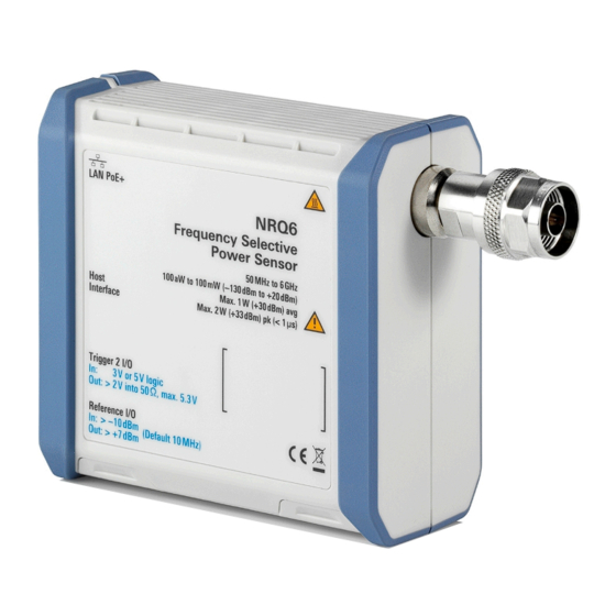
® R&S NRQ6 tour R&S NRQ6 RF connector R&S NRQ6 tour This chapter provides an overview of the available connectors and LEDs of the R&S NRQ6. Figure 4-1: R&S NRQ6 frequency selective power sensor = RF connector, see Chapter 4.1, "RF connector", on page 31 2, 10 = Fan openings, see... -
Page 32: Status Information
® R&S NRQ6 tour R&S NRQ6 LAN PoE+ interface The male N connector is used to connect the R&S NRQ6 to the device under test (DUT) or a signal generator, see Chapter 3.4, "Connecting to a DUT", on page 17. For maximum measurement accuracy, tighten the RF connector using a torque wrench with the recommended nominal torque. - Page 33 ® R&S NRQ6 tour R&S NRQ6 LAN PoE+ interface 1 Gigabit LAN interface (1000 Base-T). The assignment of the RJ.45 CAT5 con- nector supports twisted-pair UTP/STP cables in a star configuration (UTP stands for "unshielded twisted pair", and STP for "shielded twisted pair"). Electromagnetic interference (EMI) can affect the measurement results.
-
Page 34: Host Interface
® R&S NRQ6 tour R&S NRQ6 Host interface Color State Green The power sensor is correctly connected to the network. It has been assigned a valid IP address, either manually or via DHCP. The power sensor is not connected to the network correctly. Either the connection is erroneous or the sensor has not been assigned a valid IP address yet. -
Page 35: Trigger 2 I/O (Trig2)
® R&S NRQ6 tour R&S NRQ6 Clock I/O (CLK) ● Chapter 6, "Remote control interfaces and protocols", on page 49 Trigger 2 I/O (TRIG2) See (5) in Figure 4-1. The female SMA connector is used as an input or output for a trigger signal. For input and output specifications, read the label on the R&S NRQ6 casing and the data sheet. -
Page 36: Local Oscillator I/O (Lo)
® R&S NRQ6 tour R&S NRQ6 Fan openings If you supply the local oscillator signal externally, you can use an external signal as sampling clock instead of the internal signal (input). For input and output specifications, read the label on the R&S NRQ6 casing and the data sheet. -
Page 37: Operating Concepts
® Operating concepts R&S NRQ6 R&S NRP Toolkit Operating concepts For operating the R&S NRQ6, you can choose from the following possibilities: ● Chapter 5.2, "Browser-based user interface", on page 39 ● Chapter 5.3, "R&S NRX", on page 45 ● Chapter 5.4, "Remote control", on page 46... -
Page 38: System Requirements
® Operating concepts R&S NRQ6 R&S NRP Toolkit 5.1.2 System requirements Hardware requirements: ● Desktop computer or laptop, or an Intel-based Apple Mac ● LAN interface and equipment for setting up a LAN connection. Chapter 3.6.1, "Computer using a LAN connection", on page 19. -
Page 39: Browser-Based User Interface
® Operating concepts R&S NRQ6 Browser-based user interface 3. Accept the license terms to continue with the installation. 4. Click "Next" and complete the installation process. 5.1.3.1 Performing a firmware update The Firmware Update for NRP Family program is part of the R&S NRP Toolkit for Windows. - Page 40 ® Operating concepts R&S NRQ6 Browser-based user interface You can use the web user interface with all devices and operating systems, including tablets and smart phones. ● Supported web browser: – Mozilla Firefox 56 or later – Google Chrome 61 or later –...
-
Page 41: Layout Of The Main Dialog
® Operating concepts R&S NRQ6 Browser-based user interface 5.2.1 Layout of the main dialog The main dialog of the web user interface gives access to all available settings. Figure 5-1: Layout of the web user interface 1 = Navigation pane 2 = Sensor name or hostname 3 = Status information 4 = Sensor information... -
Page 42: Tooltips
® Operating concepts R&S NRQ6 Browser-based user interface Sensor information (3) in Figure 5-1 Serial number of the R&S NRQ6 and installed firmware version Top pane (4) in Figure 5-1 Stays always visible. Navigation pane (5) in Figure 5-1 For displaying measurement and system settings in the settings pane. Settings pane (6) in Figure 5-1... -
Page 43: Toolbar In Charts
® Operating concepts R&S NRQ6 Browser-based user interface 5.2.3 Toolbar in charts If you move the mouse into a chart, a toolbar becomes visible in the upper right corner. Use the toolbar to analyze the chart in detail. Table 5-1: Icons for chart analysis Icon Description Downloads the chart in PNG format. - Page 44 ® Operating concepts R&S NRQ6 Browser-based user interface Table 5-2: Short forms of units Quantity Short Corresponding forms * unit Frequency Time μs * Both capital and small letters are accepted. ► If you want to change a number, you can also: ●...
-
Page 45: R&S Nrx
® Operating concepts R&S NRQ6 R&S NRX To toggle between two possible values If only two values are possible, you can toggle between these values. Toggling works for the pairs "Off"/"On", "Auto"/"Manual", "Left"/"Right", etc. ► Click the value to change to the other value. R&S NRX In a measurement, the R&S NRX uses all power sensor-dependent measurement functions and displays the results. -
Page 46: Remote Control
® Operating concepts R&S NRQ6 Remote control b) Tap "Quick Setup" > "Auto Set". 4. Switch on the signal source. The measurement starts, and the result is displayed in dBm. 5. If necessary, perform further settings. Remote control You can remote control the R&S NRQ6 easily. The change to remote control occurs "on the fly". - Page 47 ® Operating concepts R&S NRQ6 Remote control The R&S NRQ6 changes into local mode. The lock of the web user interface is removed. Further information: ● See the user manual for details. ● Chapter 6, "Remote control interfaces and protocols", on page 49 ●...
- Page 48 ® Operating concepts R&S NRQ6 Remote control Getting Started 1178.3705.02 ─ 10...
-
Page 49: Remote Control Interfaces And Protocols
® Remote control interfaces and protocols R&S NRQ6 USB interface Remote control interfaces and protocols For remote control, communication between the R&S NRQ6 and the controlling host is established based on the following interfaces and protocols. Table 6-1: Supported interfaces and protocols Interface Protocol Library VISA... - Page 50 ® Remote control interfaces and protocols R&S NRQ6 USB interface Setup 1. Connect the host interface of the R&S NRQ6 and the USB interface of the computer. Chapter 3.6.2, "Computer using a USB connection", on page 24. 2. Make sure that the R&S NRQ6 is powered by PoE+. For details, see "R&S NRQ6 requires PoE+"...
-
Page 51: Ethernet Interface
® Remote control interfaces and protocols R&S NRQ6 Ethernet interface Ethernet interface The Ethernet interface of the R&S NRQ6 allows you to integrate it in a local area network (LAN). Requirements ● TCP/IP network protocol The local area network must support the TCP/IP network protocol. The TCP/IP network protocol and the associated network services are precon- figured on the R&S NRQ6. - Page 52 ® Remote control interfaces and protocols R&S NRQ6 Ethernet interface The IP address or hostname is used by the programs to identify and control the power sensor. While the hostname is determined by settings in the power sensor, the IP address is assigned by a DHCP server when the power sensor requests one.
- Page 53 ® Remote control interfaces and protocols R&S NRQ6 Ethernet interface Example: A power sensor has the IP address 10.111.11.20; the valid resource string using VXI-11 protocol is: TCPIP::10.111.11.20::INSTR The DNS host name is nrq6-100001; the valid resource string is: TCPIP::nrq6-100001::hislip0 (HiSLIP) TCPIP::nrq6-100001::inst0 (VXI-11) A raw socket connection can be established using: TCPIP::10.111.11.20::5025::SOCKET...
- Page 54 ® Remote control interfaces and protocols R&S NRQ6 Ethernet interface Getting Started 1178.3705.02 ─ 10...
-
Page 55: Contacting Customer Support
® Contacting customer support R&S NRQ6 Contacting customer support Technical support – where and when you need it For quick, expert help with any Rohde & Schwarz product, contact our customer support center. A team of highly qualified engineers provides support and works with you to find a solution to your query on any aspect of the operation, program- ming or applications of Rohde &... - Page 56 ® Contacting customer support R&S NRQ6 Getting Started 1178.3705.02 ─ 10...
-
Page 57: Index
® Index R&S NRQ6 Index Disconnecting R&S NRX ..........29 Application cards ........13 RF ............17 Application notes ........13 USB host ..........26 Application sheets ........12 Download R&S NRP Toolkit .........37 Brochures ..........12 Connecting ..........17 Browser-based user interface ....39 Disconnecting ........ - Page 58 ® Index R&S NRQ6 PoE+ Ethernet switch ......19 System requirements ......38 PoE+ injector ........ 20, 21 Versions ..........37 Setup ..........22 R&S NRP‑Z5 ........... 26 LAN connector .........32 R&S NRX ..........45 LAN interface Connecting ........18, 29 Remote control ........
- Page 59 ® Index R&S NRQ6 Unpacking ..........15 USB connection Simple ..........25 USB sensor hub ........26 USB interface Remote control ........49 USB resource string ........ 50 USB sensor hub ........26 USBTMC protocol ........50 User manual ..........11 VISA ............
Need help?
Do you have a question about the 1421.3509.02 and is the answer not in the manual?
Questions and answers