R&S NRQ6 Getting Started
Frequency selective power sensor
Hide thumbs
Also See for NRQ6:
- Getting started (59 pages) ,
- Getting started (59 pages) ,
- User manual (246 pages)
Table of Contents
Advertisement
Quick Links
Advertisement
Table of Contents

Related Manuals for R&S NRQ6


Summary of Contents for R&S NRQ6
- Page 1 ® R&S NRQ6 Frequency Selective Power Sensor Getting Started (;ÜU52) 1178370502...
- Page 2 Rohde & Schwarz GmbH & Co. KG. Trade names are trademarks of the owners. ® 1178.3705.02 | Version 07 | R&S NRQ6 ® Throughout this manual, products from Rohde & Schwarz are indicated without the symbol , e.g. ® R&S NRQ6 is indicated as R&S NRQ6.
-
Page 3: Table Of Contents
® Contents R&S NRQ6 Contents 1 Safety Information..............7 2 Documentation Overview............9 2.1 Getting Started Manual.................9 2.2 User Manual...................9 2.3 CD-ROM....................9 2.4 Application Sheets................10 2.5 Tutorials....................10 2.6 Instrument Security Procedures............10 2.7 Basic Safety Instructions..............10 2.8 Data Sheets and Brochures............... 10 2.9 Release Notes and Open Source Acknowledgment (OSA)..... - Page 4 4.6.2 Computer Using a USB Connection............. 25 4.6.2.1 Simple USB Connection............... 25 4.6.2.2 R&S NRP‑Z5 Sensor Hub Setup............26 4.6.3 R&S NRX Base Unit................28 5 R&S NRQ6 Tour..............31 5.1 RF Connector..................32 5.2 Status Information................32 5.3 LAN PoE+ Interface................33 5.4 Host Interface..................
- Page 5 ® Contents R&S NRQ6 6.2.3 Toolbar in Charts...................45 6.2.4 Setting Parameters................45 6.3 R&S NRX....................47 6.4 Remote Control................... 48 7 Remote Control Interfaces and Protocols......51 7.1 USB Interface..................51 7.2 Ethernet Interface................53 7.2.1 VISA Resource Strings................. 53 7.2.2 VXI-11 Protocol..................55 7.2.3 HiSLIP Protocol..................55...
- Page 6 ® Contents R&S NRQ6 Getting Started 1178.3705.02 ─ 07...
-
Page 7: Safety Information
R&S NRQ6 Safety Information The product documentation helps you use the R&S NRQ6 safely and efficiently. Follow the instructions provided here and in the printed "Basic Safety Instruc- tions". Keep the product documentation nearby and offer it to other users. - Page 8 ® Safety Information R&S NRQ6 Getting Started 1178.3705.02 ─ 07...
-
Page 9: Documentation Overview
Getting Started Manual Introduces the R&S NRQ6 and describes how to set up and start working with the product. A printed version is delivered with the R&S NRQ6. User Manual Contains the description of all instrument modes and functions. It also provides... -
Page 10: Application Sheets
Tutorials offer guided examples and demonstrations on operating the R&S NRQ6. They are provided on the product page of the internet. Instrument Security Procedures Deals with security issues when working with the R&S NRQ6 in secure areas. It is available for download on the Internet. Basic Safety Instructions Contains safety instructions, operating conditions and further important informa- tion. -
Page 11: Release Notes And Open Source Acknowledgment (Osa)
® Documentation Overview R&S NRQ6 Application Notes, Application Cards, White Papers, etc. Release Notes and Open Source Acknowledg- ment (OSA) The release notes list new features, improvements and known issues of the cur- rent firmware version, and describe the firmware installation. - Page 12 ® Documentation Overview R&S NRQ6 Application Notes, Application Cards, White Papers, etc. Getting Started 1178.3705.02 ─ 07...
-
Page 13: Key Features
R&S NRQ6 Key Features The R&S NRQ6 frequency selective power sensor sets standards in RF perfor- mance and usability. Outstanding key features are: ● Combines the advantages of a measurement receiver (dynamic range, linear- ity & video bandwidth) and a conventional diode-based or thermal power sen- sor (stability, absolute accuracy &... - Page 14 ® Key Features R&S NRQ6 Getting Started 1178.3705.02 ─ 07...
-
Page 15: Preparing For Use
Check the equipment for completeness using the delivery note and the accessory lists for the various items. Check the R&S NRQ6 for any damage. If there is dam- age, immediately contact the carrier who delivered the power sensor. Make sure not to discard the box and packing material. -
Page 16: Considerations For Test Setup
Considerations for Test Setup on the power sensor, observe the information on appropriate operating conditions provided in the basic safety instructions and the data sheet of the R&S NRQ6. In particular, ensure the following: ● The power sensor is dry and shows no sign of condensation. -
Page 17: Connecting To A Dut
NRQ6 Connecting to a DUT Connecting to a DUT The R&S NRQ6 has fan openings at both sides of the casing, as shown in Fig- 5-1. When connecting the R&S NRQ6 to a DUT and setting up the measure- ment assembly, be careful to allow sufficient airflow. -
Page 18: Connecting To A Power Supply
Carefully loosen the union nut at the front of the RF connector of the R&S NRQ6. 2. Remove the R&S NRQ6. Connecting to a Power Supply The power for the R&S NRQ6 is supplied over the LAN PoE+ interface. See also Chapter 5.3, "LAN PoE+ Interface", on page 33. -
Page 19: Connecting To A Controlling Host
R&S NRX Base Unit..................28 4.6.1 Computer Using a LAN Connection There are different ways to connect the R&S NRQ6 to a computer according to the available equipment. The power for the R&S NRQ6 is supplied over the LAN PoE+ interface. Further information: ●... -
Page 20: Setup With A Poe+ Ethernet Switch
= RJ.45 Ethernet connector 4, 6 = RJ.45 Ethernet cable = Ethernet switch supporting PoE+ power delivery = Computer 1. Connect the [RF] connector of the R&S NRQ6 to the DUT, see Chapter 4.4, "Connecting to a DUT", on page 17. -
Page 21: Setup With A Poe+ Injector And A Non-Poe+ Ethernet Switch
"Connecting to a DUT", on page 17. 2. Connect the RJ.45 Ethernet connector of the R&S NRQ6 to the output of the PoE+ injector. 3. Connect the PoE+ injector to a power supply. 4. Connect the input of the PoE+ injector to the non-PoE+ Ethernet switch. -
Page 22: Setup With A Poe+ Injector
"Connecting to a DUT", on page 17. 2. Connect the RJ.45 Ethernet connector of the R&S NRQ6 to the output of the PoE+ injector. 3. Connect the PoE+ injector to a power supply. 4. Connect the computer to the input of the PoE+ injector. -
Page 23: Using Hostnames
By default, the R&S NRQ6 is configured to use dynamic TCP/IP configuration (DHCP) and to obtain the address information automatically. If both LAN status LEDs are illuminated in green color, the R&S NRQ6 is cor- rectly connected to the network. -
Page 24: Assigning The Ip Address
(DHCP), the address information is assigned automati- cally. ● If the network does not support DHCP, the R&S NRQ6 tries to obtain the IP address via the Zeroconf (APIPA = automatic private IP addressing) protocol. If this attempt does not succeed or if the R&S NRQ6 is set to use alternate TCP/IP configuration, you have to set the IP address manually. -
Page 25: Computer Using A Usb Connection
R&S NRQ6 by the same identification, irrespective of whether it is a net- work or a point-to-point connection. 4.6.2 Computer Using a USB Connection You can connect an R&S NRQ6 to a computer using the host interface and con- trol it as described in Chapter 6, "Operating Concepts", on page 39. -
Page 26: R&S Nrp-Z5 Sensor Hub Setup
5 = USB connector 6 = Computer with installed VISA driver or R&S NRP Toolkit 7 = PoE+ injector 8 = AC supply 1. Connect the R&S NRQ6 to the signal source (DUT), see Chapter 4.4, "Con- necting to a DUT", on page 17. - Page 27 = Host interface connector = R&S NRQ6 = Signal source (DUT) = PoE+ injector = AC supply 1. Connect each R&S NRQ6 to: a) Signal source (DUT), see Chapter 4.4, "Connecting to a DUT", on page 17. b) Power supply, see Chapter 4.5, "Connecting to a Power...
-
Page 28: R&S Nrx Base Unit
4.6.3 R&S NRX Base Unit You can use an R&S NRX base unit as controlling host. Connect the R&S NRQ6 to the R&S NRX using the host interface. The R&S NRX supports the configura- tion of 2 directly connected R&S NRQ6, if enhanced accordingly. For details, see the user manual and the data sheet of the R&S NRX. - Page 29 Insert this connector into one of the sensor ports of the R&S NRX. ► If you want to disconnect the cable from the host interface of the R&S NRQ6: a) Loosen the union nut of the screw-lock cable connector.
- Page 30 ® Preparing for Use R&S NRQ6 Connecting to a Controlling Host Getting Started 1178.3705.02 ─ 07...
-
Page 31: S Nrq6 Tour
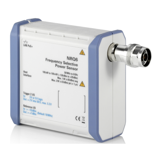
R&S NRQ6 R&S NRQ6 Tour This chapter provides an overview of the available connectors and LEDs of the R&S NRQ6. Figure 5-1: R&S NRQ6 frequency selective power sensor = RF connector, see Chapter 5.1, "RF Connector", on page 32 = Status display, see Chapter 5.2, "Status... -
Page 32: Rf Connector
Status Information RF Connector See (1) in Figure 5-1. The male N connector is used to connect the R&S NRQ6 to the device under test (DUT) or a signal generator, see Chapter 4.4, "Connecting to a DUT", on page 17. -
Page 33: Lan Poe+ Interface
5 cables or better. The power for the R&S NRQ6 is supplied over the LAN PoE+ interface. The LAN PoE+ interface also connects the R&S NRQ6 to a local area network (LAN) for remote control, remote operation and data transfer. - Page 34 IP address yet. PoE+ status LED See (2) in Figure 5-2. Shows whether the R&S NRQ6 is correctly powered over PoE+ or not. Color State Green The sensor is powered over PoE+. You can operate it using the Ethernet inter- face.
-
Page 35: Host Interface
Host Interface See (4) in Figure 5-1. The 8-pole male sensor connector (M12) is used to connect the R&S NRQ6 to a computer or an R&S NRX base unit. Further information: ● Chapter 4.6.1, "Computer Using a LAN Connection",... -
Page 36: Clock I/O (Clk)
(output). Also, you can supply an external reference signal and use it as refer- ence clock instead of the internal reference signal (input). For input and output specifications, read the label on the R&S NRQ6 casing and the data sheet. -
Page 37: Fan Openings
See (9, 10) in Figure 5-1. The R&S NRQ6 has fan openings on the top and on the bottom of the casing. When connecting the R&S NRQ6, be careful to allow sufficient airflow as speci- fied in Chapter 4.4, "Connecting to a DUT",... - Page 38 ® R&S NRQ6 Tour R&S NRQ6 Fan Openings Getting Started 1178.3705.02 ─ 07...
-
Page 39: Operating Concepts
Chapter 6.4, "Remote Control", on page 48 Also, the R&S NRQ6 is supported by the R&S Power Viewer. The R&S Power Viewer is provided on your documentation CD-ROM and on the Rohde & Schwarz website as a separate standalone installation package. -
Page 40: System Requirements
® Operating Concepts R&S NRQ6 R&S NRP Toolkit 6.1.2 System Requirements Hardware requirements: ● Desktop computer or laptop, or an Intel-based Apple Mac ● LAN interface and equipment for setting up a LAN connection. Chapter 4.6.1, "Computer Using a LAN Connection",... -
Page 41: Performing A Firmware Update
For further details, refer to the user manual. Browser-Based User Interface With the integrated, browser-based graphical user interface of the R&S NRQ6, you can easily configure the settings and measure in the provided measurement modes. Open a web browser on your controlling host and connect to the R&S NRQ6. - Page 42 DUT", on page 17. To display the Web user interface 1. Open a supported web browser. 2. Enter the hostname of the R&S NRQ6 you want to connect to. See Chap- ter 4.6.1.5, "Using Hostnames", on page 23.
-
Page 43: Layout Of The Main Dialog
If you do not specify a sensor name, the hostname is displayed. For details, see the user manual. Status information (2) in Figure 6-1 Displays the status of the R&S NRQ6. The colors are explained in Chapter 5.2, "Status Information", on page 32. -
Page 44: Tooltips
® Operating Concepts R&S NRQ6 Browser-Based User Interface If the R&S NRQ6 is in remote mode, the status is displayed next to the status LED, see Figure 6-2. Sensor information (3) in Figure 6-1 Serial number of the R&S NRQ6 and installed firmware version... -
Page 45: Toolbar In Charts
® Operating Concepts R&S NRQ6 Browser-Based User Interface 6.2.3 Toolbar in Charts If you move the mouse into a chart, a toolbar becomes visible in the upper right corner. Use the toolbar to analyze the chart in detail. Table 6-1: Icons for chart analysis... - Page 46 ® Operating Concepts R&S NRQ6 Browser-Based User Interface Table 6-2 for the available short forms of units. Table 6-2: Short forms of units Quantity Short Corresponding forms * unit Frequency Time μs * Both capital and small letters are accepted.
-
Page 47: R&S Nrx
® Operating Concepts R&S NRQ6 R&S NRX To toggle between two possible values If only two values are possible, you can toggle between these values. Toggling works for the pairs "Off"/"On", "Auto"/"Manual", "Left"/"Right", etc. ► Click the value to change to the other value. -
Page 48: Remote Control
For a detailed description of how to measure in this setup, refer to the user man- ual of the R&S NRX. Remote Control You can remote control the R&S NRQ6 easily. The change to remote control occurs "on the fly". Switching to remote control 1. - Page 49 ® Operating Concepts R&S NRQ6 Remote Control The R&S NRQ6 changes into local mode. The lock of the web user interface is removed. Further information: ● See the user manual for details. ● Chapter 7, "Remote Control Interfaces and Protocols", on page 51 ●...
- Page 50 ® Operating Concepts R&S NRQ6 Remote Control Getting Started 1178.3705.02 ─ 07...
-
Page 51: Remote Control Interfaces And Protocols
R&S NRQ6 USB Interface Remote Control Interfaces and Proto- cols For remote control, communication between the R&S NRQ6 and the controlling host is established based on the following interfaces and protocols. Table 7-1: Supported interfaces and protocols Interface Protocol Library... - Page 52 Apart from the USBTMC driver, which comes with the installation of the R&S NRP Toolkit, you do not have to install a separate driver. Setup 1. Connect the host interface of the R&S NRQ6 and the USB interface of the computer, see Chapter 4.6.2, "Computer Using a USB Connection",...
-
Page 53: Ethernet Interface
Remote Control Interfaces and Protocols R&S NRQ6 Ethernet Interface Ethernet Interface The Ethernet interface of the R&S NRQ6 allows you to integrate it in a local area network (LAN). Requirements ● TCP/IP network protocol The local area network must support the TCP/IP network protocol. - Page 54 ® Remote Control Interfaces and Protocols R&S NRQ6 Ethernet Interface The IP address or hostname is used by the programs to identify and control the sensor. While the hostname is determined by settings in the sensor, the IP address is assigned by a DHCP server when the sensor requests one. Alterna- tively the IP address is determined with a procedure called Zeroconf.
-
Page 55: Vxi-11 Protocol
Example: A power sensor has the IP address 10.111.11.20; the valid resource string using VXI-11 protocol is: TCPIP::10.111.11.20::INSTR The DNS hostname is nrq6-100001; the valid resource string is: TCPIP::nrq6-100001::hislip0 (HiSLIP) TCPIP::nrq6-100001::inst0 (VXI-11) A raw socket connection can be established using: TCPIP::10.111.11.20::5025::SOCKET... -
Page 56: Socket Communication
® Remote Control Interfaces and Protocols R&S NRQ6 Ethernet Interface The HiSLIP data is sent to the device using the "fire and forget" method with immediate return. Opposed to VXI-11, where each operation is blocked until a VXI-11 device handshake returns. Thus, a successful return of a VISA operation such as viWrite() does not guarantee that the sensor has finished (or even started) executing the requested command. -
Page 57: Contacting Customer Support
® Contacting Customer Support R&S NRQ6 Contacting Customer Support Technical support – where and when you need it For quick, expert help with any Rohde & Schwarz product, contact our customer support center. A team of highly qualified engineers provides support and works with you to find a solution to your query on any aspect of the operation, program- ming or applications of Rohde &... - Page 58 ® Contacting Customer Support R&S NRQ6 Getting Started 1178.3705.02 ─ 07...
-
Page 59: Index
® Index R&S NRQ6 Index Disconnecting DUT ............ 18 Accessory list .......... 15 R&S NRX ..........29 Application cards ........11 USB host ..........26 Application notes ........11 Download Application sheets ........10 R&S NRP Toolkit .........39 Connecting ..........17 Brochures ..........10 Disconnecting ........ - Page 60 ® Index R&S NRQ6 LAN connection Hostname ........... 23 R&S NRP Toolkit ........39 IP address ...........24 Components for Windows-based sys- Non-PoE+ Ethernet switch ....21 tems ............ 40 PoE+ Ethernet switch ......20 Firmware update ......... 41 PoE+ injector ........ 21, 22 Installation under Windows ....
- Page 61 ® Index R&S NRQ6 Toolbar Chart ........... 45 Tooltips ............ 44 Trigger connector ........35 Tutorials ........... 10 Unpacking ..........15 USB connection Simple ..........25 USB sensor hub ........26 USB interface Remote control ........51 USB resource string ........ 52 USB sensor hub ........
Need help?
Do you have a question about the NRQ6 and is the answer not in the manual?
Questions and answers