Sign In
Upload
Download
Table of Contents
Contents
Add to my manuals
Delete from my manuals
Share
URL of this page:
HTML Link:
Bookmark this page
Add
Manual will be automatically added to "My Manuals"
Print this page
×
Bookmark added
×
Added to my manuals
Manuals
Brands
R&S Manuals
Accessories
NRT-Z14
Getting started
R&S NRT-Z14 Getting Started
Directional power sensor
Hide thumbs
Also See for NRT-Z14
:
Supplement to operating manual
(19 pages)
1
2
Table Of Contents
3
4
5
6
7
8
9
10
11
12
13
14
15
16
17
18
19
20
21
22
23
24
25
26
27
28
29
30
31
32
33
34
page
of
34
Go
/
34
Contents
Table of Contents
Bookmarks
Table of Contents
Table of Contents
Safety and Regulatory Information
Safety Instructions
Labels on the Product
Warning Messages in the Documentation
Welcome
Documentation Overview
Getting Started Manual
User Manual
Tutorials
Instrument Security Procedures
Printed Safety Instructions
Data Sheets and Brochures
Application Notes, Application Cards, White Papers, Etc
Key Features
Preparing for Use
Unpacking and Checking
Choosing the Operating Site
Considerations for Test Setup
Connecting to Source and Load
Connecting to a Computer or Base Unit
Computer
Base Unit
Legacy Setups
Power Sensor Tour
RF Connectors
Host Interface
Power Handling Capacity
R&S NRT-Z5 USB Interface Adapter
Operating Concepts
Base Unit
R&S Virtual NRT
Remote Control
Remote Control Using R&S Virtual NRT
Remote Control Using Terminal Program
Index
Advertisement
Quick Links
1
Table of Contents
2
User Manual
3
Connecting to a Computer or Base Unit
4
R&S Nrt-Z5 Usb Interface Adapter
5
R&S Virtual Nrt
Download this manual
®
R&S
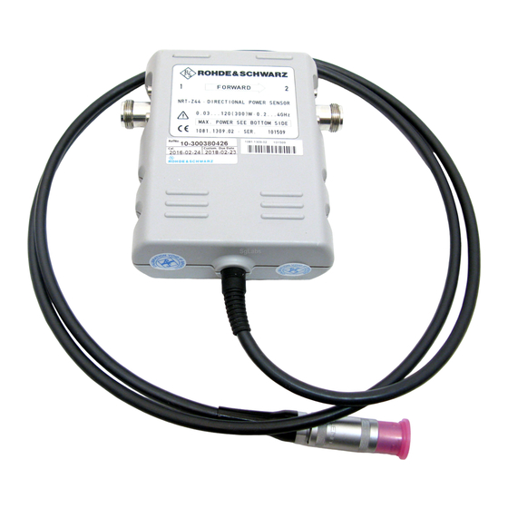
NRT-Z14/44
Directional Power Sensor
Getting Started
(>[äP2)
1443863202
Version 01
Table of
Contents
Previous
Page
Next
Page
1
2
3
4
5
Advertisement
Table of Contents
Need help?
Do you have a question about the NRT-Z14 and is the answer not in the manual?
Ask a question
Questions and answers
Subscribe to Our Youtube Channel
Related Manuals for R&S NRT-Z14
Accessories R&S NRT-Z14 Supplement To Operating Manual
Directional power sensor with r&s nrt-z5 usb interface adapter (19 pages)
Accessories R&S NRPxxS Series User Manual
Three-path power sensors (184 pages)
Accessories R&S NRP Series User Manual
(185 pages)
Accessories R&S NRP Series Getting Started
Power sensors (52 pages)
Accessories R&S NRP18S Series User Manual
High-power three-path diode power sensors (162 pages)
Accessories R&S NRQ6 Getting Started
Frequency selective power sensor (61 pages)
Accessories R&S NRQ6 Getting Started
Frequency selective power sensor (59 pages)
Accessories R&S NRT-Z5 Getting Started
Directional power sensor (34 pages)
Accessories R&S NRP Series User Manual
Average power sensors (161 pages)
Accessories R&S NRP-Z11 Operating Manual
Average power sensor (20 pages)
Accessories R&S NRP P Series User Manual
Pulse power sensors (152 pages)
Accessories R&S NRP18P User Manual
Pulse power sensors (152 pages)
Accessories R&S NRP40P User Manual
Pulse power sensors (152 pages)
Accessories R&S NRP33T Getting Started
Power sensors (52 pages)
Accessories R&S NRP40T Getting Started
Power sensors (52 pages)
Accessories R&S NRP110T Getting Started
Power sensors (52 pages)
This manual is also suitable for:
Nrt-z44
Nrt-z5
Table of Contents
Print
Rename the bookmark
Delete bookmark?
Delete from my manuals?
Login
Sign In
OR
Sign in with Facebook
Sign in with Google
Upload manual
Upload from disk
Upload from URL


Need help?
Do you have a question about the NRT-Z14 and is the answer not in the manual?
Questions and answers