Table of Contents
Advertisement
Quick Links
Advertisement
Table of Contents

Subscribe to Our Youtube Channel
Related Manuals for Sacmi PMV 224


Summary of Contents for Sacmi PMV 224
- Page 1 D O C U M E N T A Z I O N E MAINTENANCE AND OPERATIONS MANUAL 176.12 .A03_01 MACHINE FOR FORMING LINERS INSIDE PLASTIC CAPS PMV 224 - PMV 238 TECHNICAL DOCUMENTATION DOCUMENTATION TECHNIQUE TECHNISCHE DOKUMENTATION DOCUMENTACION TECNICA DOCUMENTAÇAO...
- Page 2 176.12 .A03 Revision 01 Date 14.11.2001 TABLE OF CONTENTS 0 - 2...
- Page 3 PMV 224 - PMV 238 MANUFACTURER SACMI IMOLA Via Selice Provinciale, 17/A 40026 IMOLA (Bologna) - ITALIA SERIAL NUMBER YEAR OF MANUFACTURE PUBLISHED ON 30.10.2000 REVISION 01 - 14.11.2001 VERSIONS PMV 224.00.000/001 - PMV 224A - PMV 238.00.002/003 - PMV 238A 0 - 3...
- Page 4 176.12 .A03 Revision 01 Date 14.11.2001 TABLE OF CONTENTS 0 - 4...
-
Page 5: Table Of Contents
176.12 .A03 Revision 01 Date 14.11.2001 TABLE OF CONTENTS Page GENERAL INFORMATION ........................1 - 1 INTRODUCTION .........................1 - 1 WHERE TO KEEP THE MANUAL ....................1 - 1 HOW TO USE THE MANUAL .....................1 - 1 USERS OF THE MANUAL ......................1 - 1 WARRANTY ..........................1 - 2 SUPPLEMENTS ..........................1 - 2 KEY TO THE SAFETY SYMBOLS USED ON THE MACHINE... - Page 6 176.12 .A03 Revision 01 Date 14.11.2001 TABLE OF CONTENTS Page SAFETY EQUIPMENT AND PRECAUTIONS .................... 3 - 1 SAFETY DEVICES AND GUARDS ..................... 3 - 1 3.1.1 GENERAL SAFETY RULES ......................3 - 1 3.1.2 SAFETY DEVICES INSTALLED ....................3 - 1 3.1.2.1 SHUTDOWN DEVICES .......................
- Page 7 176.12 .A03 Revision 01 Date 14.11.2001 TABLE OF CONTENTS Page INSTALLATION ............................4 - 1 MACHINE SHIPMENT ........................ 4 - 1 4.1.1 HOW THE MACHINE IS SUBDIVIDED FOR SHIPMENT ............4 - 1 4.1.2 WEIGHTS AND DIMENSIONS ....................4 - 2 4.1.3 HANDLING THE MACHINE PARTS ....................
- Page 8 176.12 .A03 Revision 01 Date 14.11.2001 TABLE OF CONTENTS Page ADJUSTMENTS ............................7 - 1 ADJUSTING THE EXTRUDER ....................7 - 1 7.1.1 ADJUSTING THE POSITION OF THE EXTRUDER NOZZLE HOLE ......... 7 - 2 7.1.2 EXTRUDER NOZZLE HEIGHT ADJUSTMENT ................7 - 3 7.1.3 CUTTER CLEARANCE ADJUSTMENT ..................
-
Page 9: General Information
This manual contains important information for safeguarding the operators, the maintenance staff and the machine itself. SACMI reserves the right to make changes to the machine and in the manual without giving prior notice. Additional copies of this manual can be obtained by contacting SACMI’s Customer Service Department. -
Page 10: Warranty
SACMI shall be held responsible only for the machine as it was configured at the time of delivery. Any operations that alter the configuration of the machine or operating cycle must be carried out by SACMI personnel or duly authorized by SACMI’S Engineering Dept. -
Page 11: Key To The Safety Symbols Used On The Machine And/Or In The Manual
176.12 .A03 Revision 01 Date 14.11.2001 GENERAL INFORMATION KEY TO THE SAFETY SYMBOLS USED ON THE MACHINE AND/OR IN THE MANUAL WARNING SYMBOLS General hazard E0004 Danger of being burnt by hot surfaces E0002 Danger of getting your hands crushed E0003 Danger of electrocution E0007... -
Page 12: Machine Identification Plate
176.12 .A03 Revision 01 Date 14.11.2001 GENERAL INFORMATION ALERT SYMBOLS Heavy duty work gloves must be worn E0005 The point indicated must be effectively earthed. E0006 MACHINE IDENTIFICATION PLATE FIGURE 1.8 - LOCATION OF THE MACHINE IDENTIFICATION PLATE T2450 1 - 4... -
Page 13: Main Features
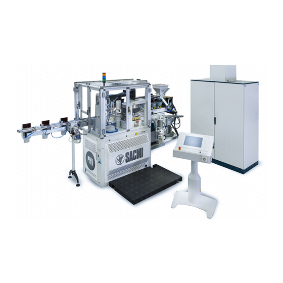
176.12 .A03 Revision 01 Date 14.11.2001 MAIN FEATURES MAIN FEATURES MACHINE DESCRIPTION This machine, which operates with a continuous work cycle, is designed to form liners made of thermoplastic material inside caps. The work cycle begins with the plastic material coming out of the extruder. A plastic pellet of a pre-determined size is then cut and placed inside the cap. -
Page 14: Main Machine Assemblies
176.12 .A03 Revision 01 Date 14.11.2001 MAIN FEATURES 2.1.1 MAIN MACHINE ASSEMBLIES 2.1.1.1 Extruder This unit is used to melt the granular material and force it out of a suitably sized port at the required temperature. The size of the outlet depends on the type of plastic compound being handled. The equipment on the drum cuts the extruded material into pellets and places them in the caps. -
Page 15: Insertion Drum
176.12 .A03 Revision 01 Date 14.11.2001 MAIN FEATURES 2.1.1.2 Insertion drum This unit is used to cut the extruded plastic material into small pellets and place them in the caps. The drum comes equipped with spindles (1). Cutters (2), which cut the plastic into pellets and place them in the caps, are attached to the bottom of the spindles. -
Page 16: 1St Transfer Unit
176.12 .A03 Revision 01 Date 14.11.2001 MAIN FEATURES 2.1.1.3 1st transfer unit This unit transfers the caps from the insertion to the forming drum. To do this, the caps are held in place between the transfer wheels (adjustable) and external guides. When in the section that leads to the forming unit, the caps are held in place from the top by a cover. -
Page 17: Forming Unit
176.12 .A03 Revision 01 Date 14.11.2001 MAIN FEATURES 2.1.1.4 Forming unit This assembly is used to form the liners inside the caps by compressing the pellets. The upper part of the drum houses the fixed forming plungers (2). The lower part contains the spindles that hold the caps (1). -
Page 18: 2Nd Transfer Unit
176.12 .A03 Revision 01 Date 14.11.2001 MAIN FEATURES 2.1.1.5 2nd transfer unit This unit is used to transfer the caps from the forming drum to the quality control unit. 2.1.1.6 Quality control unit This unit checks the liners to see whether they have been properly formed and that the shells have not been damaged. The unit incorporates sensing spindles (1) located in cylindrical bores equally spaced apart around the periphery of the body (2). -
Page 19: Discharge Unit
176.12 .A03 Revision 01 Date 14.11.2001 MAIN FEATURES 2.1.1.7 Discharge unit This unit is used to transfer the caps from the quality control unit to the exit conveyor belt. 2.1.1.8 Exit conveyor belt The exit conveyor belt receives the products from the discharge unit and carries them in an orderly manner to the area where they enter the next machine in-line. -
Page 20: Drive Unit & Manual Operation
176.12 .A03 Revision 01 Date 14.11.2001 MAIN FEATURES 2.1.1.9 Drive unit & manual operation The drive system operates all the units. It consists of a geared motor coupled with a worm reduction unit (1). An inverter is used to control the unit. A slip clutch (2), mounted on the output shaft of the geared motor (1), disengages the reduction gear if the machine stops abruptly. -
Page 21: 2.1.1.10 Pneumatic System
176.12 .A03 Revision 01 Date 14.11.2001 MAIN FEATURES 2.1.1.10 Pneumatic system The pneumatic system is located in a cabinet housing all the parts for air preparation (filters, pressure regulators, pressure switches, safety valves) as well as the air-operated actuator controls (solenoid valves). 2.1.1.11 Cooling system The cooling system is used to supply cooling fluid at a regulated temperature (refer to the work sheet for correct values) to the following parts:... -
Page 22: Intended, Prohibited Use And Misuse Of The Machine
176.12 .A03 Revision 01 Date 14.11.2001 MAIN FEATURES 2.1.2 INTENDED, PROHIBITED USE AND MISUSE OF THE MACHINE INTENDED USE OF THE MACHINE The machine described in this manual is specifically designed to manufacture products with the characteristics indicated in the specifications. The machine operates safely if: - it is used under the operating conditions and within the limits indicated in this paragraph;... -
Page 23: Overall Dimensions
176.12 .A03 Revision 01 Date 14.11.2001 MAIN FEATURES OVERALL DIMENSIONS FIGURE 2.2/A - PMV 224 OVERALL DIMENSIONS WITH CABINET ON RIGHT-HAND SIDE AND 20 KG/H EXTRUDER 2750 1000 1220 2020 T2428 2 - 11... - Page 24 176.12 .A03 Revision 01 Date 14.11.2001 MAIN FEATURES FIGURE 2.2/B - PMV 224 - PMV 238 OVERALL DIMENSIONS WITH CABINET ON RIGHT-HAND SIDE AND 40 KG/H EXTRUDER 2750 1000 1220 2020 T2427 2 - 12...
-
Page 25: Machine Specifications
176.12 .A03 Revision 01 Date 14.11.2001 MAIN FEATURES MACHINE SPECIFICATIONS 2.3.1 TECHNICAL DATA PMV224 PMV224 PMV238 (20 kg/h) (40 kg/h) (40 kg/h) PRODUCTION RATE (P.E-EVA-PVC Free) up to caps/min. 1200 1600 Usage (at 0.55 MPa) l/min 1200 1200 1200 Minimum pressure required POWER Heat to be dissipated kcal/h... -
Page 26: Rating Plate
176.12 .A03 Revision 01 Date 14.11.2001 MAIN FEATURES 2.3.2 ALLOWABLE FLUCTUATION OF THE VARIABLES ELECTRIC ± 10% Voltage ± 2% Frequency PNEUMATIC ± 15% Flow rate Minimum pressure Maximum pressure COOLANT ± 10% Flow rate Pressure + 20% - 10% 2.3.3 RATING PLATE FIGURE 2.3.3 - LOCATION OF THE RATING PLATE... -
Page 27: Use Of The Machine
The machine can produce thermoplastic liners inside caps. The size of the caps must correspond to that arranged for before hand with SACMI’s Engineering Dept. In any case, the dimensions must fall within the values given in the figure. TYPE OF PLASTIC COMPOUNDS... -
Page 28: Noise Emission Levels
176.12 .A03 Revision 01 Date 14.11.2001 MAIN FEATURES 2.3.5 NOISE EMISSION LEVELS The noise levels were measured on a production line made up of an ATV60, infeed channels and PMV 238 as indicated in the figure below. 2.3.5.1 Acoustic radiation pressure level (ISO/DIS 11202) Test conditions - Operating conditions: machine running with load. -
Page 29: Acoustic Power Level (Iso 3746)
176.12 .A03 Revision 01 Date 14.11.2001 MAIN FEATURES 2.3.5.2 Acoustic power level (ISO 3746) Test conditions - Operating conditions: run with load. - Type of operation: plastic liner formation for plastic caps - Operating cycle: material feed and cap formation - Test environment: factory with reflecting flooring. -
Page 30: Schematics
176.12 .A03 Revision 01 Date 14.11.2001 MAIN FEATURES SCHEMATICS 2.4.1 PNEUMATIC SYSTEM FIGURE 2.4.1 - PNEUMATIC SYSTEM SCHEMATIC T2436 2 - 18... -
Page 31: Cooling System
176.12 .A03 Revision 01 Date 14.11.2001 MAIN FEATURES 2.4.2 COOLING SYSTEM FIGURE 2.4.2/A - COOLING SYSTEM SCHEMATIC T2437 2 - 19... - Page 32 176.12 .A03 Revision 01 Date 14.11.2001 MAIN FEATURES FIGURE 2.4.2/B - LAYOUT OF COOLING SYSTEM Chiller 2M Delivery manifold, Cooling lines 2R Return manifold, Cooling lines Cooling tank & Plunger fluid heater Cooling tank, Auxiliary circuit fluid 5M Delivery manifold, Auxiliary circuit 5R Return manifold, Auxiliary circuit Plastic compound cutter Area for loading plastic compound into extruder...
-
Page 33: Vacuum System
176.12 .A03 Revision 01 Date 14.11.2001 MAIN FEATURES 2.4.3 VACUUM SYSTEM FIGURE 2.4.3 - VACUUM SYSTEM LAYOUT Pump Manifold Vacuum switch Vacuum meter Rotary distributor QUALITY CONTROL UNIT: GIOSTRA DI SCELTA: CAP CONVEYANCE TRASPORTO TAPPI QUALITY CONTROL UNIT: GIOSTRA DI SCELTA: CAP CONTROL CONTROLLO TAPPI GIOSTRA FORMATRICE:... - Page 34 176.12 .A03 Revision 01 Date 14.11.2001 MAIN FEATURES 2 - 22...
-
Page 35: Safety Equipment And Precautions
Always take all necessary safety precautions before working on the machine. SACMI shall not be held responsible for any injury to personnel or damage to the machine resulting from failure to observe these precautions or use the safety devices provided. -
Page 36: Emergency Stop Buttons
176.12 .A03 Revision 01 Date 14.11.2001 SAFETY EQUIPMENT AND PRECAUTIONS 3.1.2.4 Emergency stop buttons Emergency stop buttons on board the machine These are located in the positions indicated in the illustration below. - Operation: manual - Action: the drive system and machine motors, except those for the vacuum and suction pumps (required to transport the product) stop immediately. -
Page 37: Safety Rules For Handling
176.12 .A03 Revision 01 Date 14.11.2001 SAFETY EQUIPMENT AND PRECAUTIONS SAFETY RULES FOR HANDLING WARNING! E0004P 3.2.1 LIFTING PROCEDURES To safely and correctly lift the machine always: - use the most suitable lifting equipment with an adequate lift capacity; - cover all sharp edges with cloths and/or cardboard; - make sure the safety device for the lift hook works properly;... -
Page 38: Installation
These must conform to laws currently in force in the country where the machine is installed. SACMI shall not be held responsible for any property damage or personal injury resulting from improper installation. 3 - 4... -
Page 39: Operator Training
176.12 .A03 Revision 01 Date 14.11.2001 SAFETY EQUIPMENT AND PRECAUTIONS OPERATOR TRAINING WARNING! E0004P 3.4.1 END-USER The company using this equipment must see that their personnel: - match the requirements listed below - read and understand the manual in its entirety - are adequately instructed and trained on how to safely carry out their tasks - receive specific training on how to operate this machine correctly. -
Page 40: Safety Precautions For Operating, Adjusting And Servicing The Machine
Always take the necessary safety precautions before working on the motors. E0009 E0007 In order to ensure that the machine operates efficiently, safely and in a trouble-free manner always follow SACMI’s instructions carefully. Carry out the scheduled maintenance operations exactly as described and at the time intervals recommended. -
Page 41: Guidelines For Operation And Maintenance
176.12 .A03 Revision 01 Date 14.11.2001 SAFETY EQUIPMENT AND PRECAUTIONS 3.5.2 GUIDELINES FOR OPERATION AND MAINTENANCE 3.5.2.1 Risks deriving from high temperatures ACCESS INSIDE THE EXTRUDER GUARDS Temperatures inside the extruder guards can reach up to 280°C. Never touch any surfaces where there is a warning sign indicating the danger of being burnt. - Page 42 176.12 .A03 Revision 01 Date 14.11.2001 SAFETY EQUIPMENT AND PRECAUTIONS 3 - 8...
-
Page 43: Installation
176.12 .A03 Revision 01 Date 14.11.2001 INSTALLATION INSTALLATION MACHINE SHIPMENT 4.1.1 HOW THE MACHINE IS SUBDIVIDED FOR SHIPMENT The machine is divided into various blocks to meet shipping and installation requirements. FIGURE 4.1.1 - HOW THE MACHINE IS SUBDIVIDED FOR SHIPMENT 1 Drum base 2 Extruder base 3 Plastic compound hopper... -
Page 44: Weights And Dimensions
176.12 .A03 Revision 01 Date 14.11.2001 INSTALLATION 4.1.2 WEIGHTS AND DIMENSIONS The weight and dimensions of each individual part are based on the shipping requirements. As they are approximate, they are given for reference purposes only. It is highly important that all the parts are weighed when they reach the end-user to check that they match the weights indicated here exactly. - Page 45 176.12 .A03 Revision 01 Date 14.11.2001 INSTALLATION FIGURE 4.1.2/B - WEIGHTS AND DIMENSIONS 7 Crate with spare parts 8 Crate with tools 10 Crate containing the machine base supplied with machine supplied with machine barrier-guards kg 200 550 x 350 x 350 550 x 350 x 350 1200 9 Crate with electric cables...
-
Page 46: Handling The Machine Parts
The best systems for lifting and handling the heaviest and bulkiest parts as well as those that require special care or tools provided by Sacmi are shown in the figure. When lifting the smaller parts and packages, take great care, use the most suitable equipment and observe all safety precautions. -
Page 47: Assembling The Machine
176.12 .A03 Revision 01 Date 14.11.2001 INSTALLATION ASSEMBLING THE MACHINE FIGURE 4.2.1/A - DRUM BASE The machine assemblies must be placed in a suitable area in the work-shop, as indicated in the layout provided. The assembly operations must be carried out in the order given following the procedures described below. -
Page 48: Extruder Base
176.12 .A03 Revision 01 Date 14.11.2001 INSTALLATION 4.2.2 EXTRUDER BASE FIGURE 4.2.2/A - EXTRUDER BASE - Bring the base (2) near the unit (1). - Place the ends (A) of the extruder base (2) on the end (B) of the drum base (1). - Lay the other end (external) of the extruder base (2) on the floor. -
Page 49: Plastic Compound Feeder And Hopper
176.12 .A03 Revision 01 Date 14.11.2001 INSTALLATION 4.2.3 PLASTIC COMPOUND FEEDER AND FIGURE 4.2.3/A - PLASTIC COMPOUND FEEDER HOPPER AND HOPPER - Mount the plastic compound hopper (8) over the extruder flange (2). - Secure it with the screws (A). - Install the plastic compound feeder (9) over the hopper (8). -
Page 50: Electrical Cabinet
176.12 .A03 Revision 01 Date 14.11.2001 INSTALLATION 4.2.4 ELECTRICAL CABINET FIGURE 4.2.4 - ELECTRICAL CABINET - Lift the electrical cabinet (6) as previously directed. - Place the cabinet, following the indications given in the lay-out. Make sure it is the right distance away from the 3 - 4 machine body. -
Page 51: Connections
176.12 .A03 Revision 01 Date 14.11.2001 INSTALLATION CONNECTIONS 4.3.1 CONNECTING THE HOSES FOR THE COOLING SYSTEM 4.3.1.1 Hoses for joining the heat-exchanger to the auxiliary circuit tank The delivery and return hoses (2M & 2R respectively), which are attached to the heat-exchanger of the tank (A), lead to the extruder base and must be connected to the delivery and return manifolds (M &... -
Page 52: Forming Cam Cooling Lines
176.12 .A03 Revision 01 Date 14.11.2001 INSTALLATION 4.3.1.3 Forming cam cooling lines FIGURE 4.3.1.3 The two hoses marked with the numbers 7 (delivery) and 8 (return) that run from manifolds M and R of the extruder are found beneath the extruder base. Those running from the points of use are found beneath the drum base. -
Page 53: Connecting The Pneumatic System
176.12 .A03 Revision 01 Date 14.11.2001 INSTALLATION 4.3.2 CONNECTING THE PNEUMATIC SYSTEM FIGURE 4.3.2.1 - PNEUMATIC UNIT IMPORTANT! E0004P The machine’s pneumatic unit must be connected to the mains air supply by observing all regulations currently in force in the country where the machine is installed. -
Page 54: Connections To The Vacuum System
176.12 .A03 Revision 01 Date 14.11.2001 INSTALLATION 4.3.3 CONNECTIONS TO THE VACUUM SYSTEM FIGURE 4.3.3.1 - PLASTIC COMPOUND FEEDER 4.3.3.1 Plastic compound feeder Connect the suction hose (A) to the plastic compound feeder (if provided) as indicated in the diagram. •... -
Page 55: Waste And Burr Suction System
176.12 .A03 Revision 01 Date 14.11.2001 INSTALLATION 4.3.3.3 Waste and burr suction system FIGURE 4.3.3.3/A - WASTE & BURR SUCTION - Connect the hoses (C-D-E-F) to the filter unit at the points indicated in the diagram. - Connect the other ends of the hoses (C-D-E-F) to the machine as shown in the diagram. -
Page 56: Installing The Proximity Sensors
176.12 .A03 Revision 01 Date 14.11.2001 INSTALLATION 4.3.4 INSTALLING THE PROXIMITY SENSORS The sensors are removed after the machine has been inspected in order to prevent them from being damaged during shipment. Therefore, they must be installed (as indicated in the diagram) after the machine has been assembled. FIGURE 4.3.4 - INSTALLING THE PROXIMITY SENSORS T0402 4 - 14... -
Page 57: Electrical Connections
176.12 .A03 Revision 01 Date 14.11.2001 INSTALLATION 4.3.5 ELECTRICAL CONNECTIONS 4.3.5.1 Connecting the electrical cables After the machine has been inspected, the cables are put in place for shipment. Some cables are removed and placed in a container while others are disconnected from the cabinet and wound up. The cables are arranged as indicated in the tables and located as illustrated in the diagrams. - Page 58 176.12 .A03 Revision 01 Date 14.11.2001 INSTALLATION FIGURE 4.3.5.1/B - CONNECTING THE CABLES B - C T0615 Unwind the cables and lay them on the floor together with those removed from the crates. Cables A are to be connected directly to the electrical cabinet. Cables B and C are to be laid in the wireways.
- Page 59 176.12 .A03 Revision 01 Date 14.11.2001 INSTALLATION FIGURE 4.3.5.1/C - CONNECTING THE CABLES XJ9A XJ9B XJ18 MODEM XJ15 XJ2T XJ6 (XJ4) XJ11 RS45 XJ2 XJ2T XJ13 T2410 XJ31 XJ1 XJ1A XJ8 XJ11 XJ19 XJ1 Signal emitter cable, Machine base XJ1A Signal emitter cable, Machine base XJ2 Signal emitter cable, Extruder XJ2T Signal emitter cable, Extruder XJ3 Signal lead conduit, Extruder...
-
Page 60: Earth Connection
176.12 .A03 Revision 01 Date 14.11.2001 INSTALLATION 4.3.5.2 Earth connection WARNING! E0004P The machine must be connected to an effective earth electrode. Join the earth electrode to the point marked PE (EN60445). In addition, join the earth electrode to the connection points on the machine frame marked with the symbol E0006 (417-IEC-5019). -
Page 61: Start-Up
176.12 .A03 Revision 01 Date 14.11.2001 START-UP START-UP GENERAL The machine must be started up by qualified personnel trained in both the mechanical and electrical fields. WARNING! E0004P The operations described here can only be performed by the manufacturer’s qualified personnel who are in charge of starting up the machine for the first time as indicated in Chapter 1 - GENERAL INFORMATION. -
Page 62: Operations To Be Performed Before Starting The Production Cycle
176.12 .A03 Revision 01 Date 14.11.2001 START-UP OPERATIONS TO BE PERFORMED BEFORE STARTING THE PRODUCTION CYCLE (References given in figure 6.1). Refer to Instructions Manual B for directions on how to enter the operating parameters described in this paragraph. CONDITIONS - The machine should be energised and at the correct operating temperature. -
Page 63: Starting An Automatic Cycle
176.12 .A03 Revision 01 Date 14.11.2001 START-UP STARTING AN AUTOMATIC CYCLE (References given in figure 6.1) CONDITIONS - The machine should be energised and at the correct operating temperature. - The guards should be closed. - Turn the mode selector on the control panel to the AUT position. - Start the automatic work cycle by pressing key 1 at the same time as key 28. - Page 64 176.12 .A03 Revision 01 Date 14.11.2001 START-UP 5 - 4...
-
Page 65: Operating Instructions
176.12 .A03 Revision 01 Date 14.11.2001 OPERATING INSTRUCTIONS OPERATING INSTRUCTIONS CONTROL KEYBOARD The keyboard is used by the operator to control the machine and monitor operations. It is located on a stand and is designed so that the operator can move it around the machine and place it in the most suitable position. - Page 66 176.12 .A03 Revision 01 Date 14.11.2001 OPERATING INSTRUCTIONS FIGURE 6.1/A - CONTROL KEYBOARD CAPS CAPS POWER POWER LOCK LOCK & " SPACE CAPS PAGE LOCK SHIFT > < PAGE CTRL BKSP DOWN SET UP 19-23 T2425 Keys 9, 13, 18, 22, 26, 29 and 31 are not used. (1) If the necessary safety and control devices are provided, it is possible to activate the automatic extruder pre-heater by pressing the “Immediate start-up”...
- Page 67 176.12 .A03 Revision 01 Date 14.11.2001 OPERATING INSTRUCTIONS OPERATION 1ST KEY 2ND KEY POSITION OF KEY SELECTOR (19-23) Reset Automatic cycle start Main motor start Extruder motor start Main encoder reset SET UP Automatic cycle stop Main motor stop Extruder motor stop Extruder heater start Extruder pre-heater activation (if provided) (1) Plastic compound feeder start...
- Page 68 176.12 .A03 Revision 01 Date 14.11.2001 OPERATING INSTRUCTIONS FIGURE 6.1/B - AUXILIARY CONTROL PANEL SB1B T2703 SA1A Control panel enable selector switch SB1B Emergency stop button RESET button START button STOP button Selector switch SA1 is used to enable the auxiliary control panel. At the same time, it disables the keys of the control keyboard used to turn on the drums (step, jog and normal run controls) if the control keyboard mode selector is turned to the MAN position.
-
Page 69: Work Cycle
176.12 .A03 Revision 01 Date 14.11.2001 OPERATING INSTRUCTIONS WORK CYCLE FIGURE 6.2 - WORK CYCLE 1st Rej. 1°Sc. 2°Sc. 2nd Rej. The caps are fed continuously (facing the right way up and in lines) to the insertion drum. Insertion drum: sprue cut (if present in the cap); pellet placed in caps Plastic compound feed hopper Plastic compound extruder First transfer unit... - Page 70 176.12 .A03 Revision 01 Date 14.11.2001 OPERATING INSTRUCTIONS 6 - 6...
-
Page 71: Adjustments
176.12 .A03 Revision 01 Date 14.11.2001 ADJUSTMENTS ADJUSTMENTS ADJUSTING THE EXTRUDER Adjusting the work parameters The parameters that can be adjusted are given on the “Extruder” page of the electronic control system. These parameters include the following: - Temperature in the heated areas - Extruder motor speed % (available only for operations in manual mode) - Coolant temperature The values for these parameters are given on the “Data sheet”. -
Page 72: Adjusting The Position Of The Extruder Nozzle Hole
176.12 .A03 Revision 01 Date 14.11.2001 ADJUSTMENTS 7.1.1 ADJUSTING THE POSITION OF THE EXTRUDER NOZZLE HOLE WARNING! E0004P This operation must be carried out when the extruder has reached its correct operating temperature. Carefully follow the instructions given in the SAFETY EQUIPMENT AND PRECAUTIONS chapter, RISKS DERIVING FROM HIGH TEMPERATURES paragraph and always take the necessary safety precautions to avoid being burnt. -
Page 73: Extruder Nozzle Height Adjustment
176.12 .A03 Revision 01 Date 14.11.2001 ADJUSTMENTS 7.1.2 EXTRUDER NOZZLE HEIGHT ADJUSTMENT WARNING! E0004P This operation must be carried out when the extruder has reached its correct operating temperature. Carefully follow the instructions given in the SAFETY EQUIPMENT AND PRECAUTIONS chapter, RISKS DERIVING FROM HIGH TEMPERATURES paragraph and always take the necessary safety precautions to avoid being burnt. -
Page 74: Cutter Clearance Adjustment
176.12 .A03 Revision 01 Date 14.11.2001 ADJUSTMENTS 7.1.3 CUTTER CLEARANCE ADJUSTMENT (References given in figure 7.1.2) WARNING! E0004P This operation must be carried out when the extruder has reached its correct operating temperature. Carefully follow the instructions given in the SAFETY EQUIPMENT AND PRECAUTIONS chapter, RISKS DERIVING FROM HIGH TEMPERATURES paragraph and always take the necessary safety precautions to avoid being burnt. -
Page 75: Positioning The Extruder Nozzle
176.12 .A03 Revision 01 Date 14.11.2001 ADJUSTMENTS 7.1.4 POSITIONING THE EXTRUDER NOZZLE Proceed as directed below when removing and re-fitting the extruder nozzle. - Place the magnetic support block (B) of the comparator (A) on the side of the insertion drum (C). - Bring the comparator (A) to one end (1) of the nozzle (F). -
Page 76: Pellet Weight Adjustment
176.12 .A03 Revision 01 Date 14.11.2001 ADJUSTMENTS 7.1.5 PELLET WEIGHT ADJUSTMENT To change the weight of the liners, increase or decrease the rotational speed of the auger. To do this, use the keyboard controls to open the “extruder settings” page and change the auger rpm (refer to the Instructions B manual for directions on how to make this setting). -
Page 77: Insertion Drum Adjustment
176.12 .A03 Revision 01 Date 14.11.2001 ADJUSTMENTS INSERTION DRUM ADJUSTMENT The correct distances between the cutter and the bottom of the cap (T) as well as between the central plunger and the bottom of the cap (P) have to be determined in order for the machine to operate properly. Normally these parameters are determined during machine commissioning, as the type of plastic compound used, the weight of the pellets and the varnish applied are extremely important factors capable of affecting the whole process. -
Page 78: Cutter Height Adjustment
176.12 .A03 Revision 01 Date 14.11.2001 ADJUSTMENTS 7.2.1 CUTTER HEIGHT ADJUSTMENT - Position the three comparators (6) at 120° on the cam (1) as shown in the diagram (in zones 4). - Set the comparators (6) to “zero”. - Loosen the screws (2). - Loosen or tighten the grub screws (3) to raise or lower the cam (1). -
Page 79: Plunger Height Adjustment
176.12 .A03 Revision 01 Date 14.11.2001 ADJUSTMENTS 7.2.2 PLUNGER HEIGHT ADJUSTMENT - Remove the screws (1 & 2). - Pull the blocks (3) away from the cam (4) so that they can be taken off from the bottom. - Remove or put in the spacers (5) to raise or lower the cam (4), along with the center plunger on the spindle, as required (each spacer is 0.5 mm thick). -
Page 80: Adjusting The Air Supply
176.12 .A03 Revision 01 Date 14.11.2001 ADJUSTMENTS 7.2.3 ADJUSTING THE AIR SUPPLY The air pressure must be 3.5 bar. The pressure can be adjusted by using the pressure control (1) located in the pneumatic unit. FIGURE 7.2.3 - PNEUMATIC UNIT T0428 7 - 10... -
Page 81: Timing Pellet Cutting
176.12 .A03 Revision 01 Date 14.11.2001 ADJUSTMENTS 7.2.4 TIMING PELLET CUTTING While the pellets are being cut, they are turned so that they stay in the cutter but are brought slightly in front of its axis. In order for the liners to be properly formed, the pellets must be placed in the middle of the caps and the spindle must be slightly behind the center of the cap. -
Page 82: Centering The Pellets
176.12 .A03 Revision 01 Date 14.11.2001 ADJUSTMENTS 7.2.5 CENTERING THE PELLETS In order to obtain good quality liners, the pellets must be perfectly centered. The cutter can be shifted radially in relation to the drum. Five position are available with movements ranging from “zero” to 1 mm. The positions are numbered and all the cutters must be placed at the corresponding number. -
Page 83: Adjusting The 1St Transfer Turn-Table
176.12 .A03 Revision 01 Date 14.11.2001 ADJUSTMENTS ADJUSTING THE 1ST TRANSFER TURN-TABLE The transfer turn-table (1) includes two overlapping wheels. The clearance between the cap and guides (2) can be modified by loosening the three fixing screws and moving one in relation to the other. -
Page 84: Adjusting The Forming Unit
176.12 .A03 Revision 01 Date 14.11.2001 ADJUSTMENTS ADJUSTING THE FORMING UNIT 7.4.1 FORMING PLUNGER CLEARANCE The clearance of the forming plunger is the space left between the lower and forming plungers (1 & 2 respectively), with no caps, after the lower plunger (1) has reached the cam (3) in its highest position (setting “A” in the diagram). This distance affects how the liners are formed, especially in the middle. -
Page 85: Stripper Height Adjustment
If the shim supplied with the machine is not available, keep in mind that the difference between the height of the stripper (4) placed on a cap (3) and the height of the stripper without a cap (3) must fall within 0.7 - 0.8 mm. FIGURE 7.4.2/A - PMV 224 STRIPPER HEIGHT ADJUSTMENT T2429... -
Page 86: Plunger Temperature Setting
176.12 .A03 Revision 01 Date 14.11.2001 ADJUSTMENTS FIGURE 7.4.2/B - PMV 238 STRIPPER HEIGHT ADJUSTMENT FORMING WITHOUT CAP FORMING WITH CAP Lower plunger Stripper Shim Spring Mobile bush T0631 7.4.3 PLUNGER TEMPERATURE SETTING Cooling fluid circulates inside the forming plungers. The temperature of the fluid varies according to the type of plastic compound being used. -
Page 87: Adjusting The Quality Control Unit
176.12 .A03 Revision 01 Date 14.11.2001 ADJUSTMENTS ADJUSTING THE QUALITY CONTROL UNIT Set the sensors for inspecting the liners and check their operating positions. The adjustments required depend on the profile of the liner; at times, the sensors may have to be replaced. Also check the sensor that monitors thickness and the vacuum system settings. -
Page 88: Adjusting The Height Of The Sensing Equipment And Central Sensor
176.12 .A03 Revision 01 Date 14.11.2001 ADJUSTMENTS 7.5.1 ADJUSTING THE HEIGHT OF THE SENSING EQUIPMENT AND CENTRAL SENSOR These adjustments must be carried out on a work-bench. First of all, remove the sensors from the machine by performing the following steps: - Loosen the nut (3). -
Page 89: Adjusting The Height Of The Sensing Spindles
176.12 .A03 Revision 01 Date 14.11.2001 ADJUSTMENTS 7.5.2 ADJUSTING THE HEIGHT OF THE SENSING SPINDLES To make this adjustment it is necessary to raise or lower the cam which the sensing spindles are attached to. The central sensors must be positioned at a distance Y from the surface the caps rest on as indicated in the diagram. - Position three comparators (1) on the cam (4) at 120°... -
Page 90: Adjusting The Position Of The Sensing Spindle/Liner
176.12 .A03 Revision 01 Date 14.11.2001 ADJUSTMENTS 7.5.3 ADJUSTING THE POSITION OF THE SENSING SPINDLE/LINER The liners are always checked on the outermost part. The height of the sensing spindle in relation to the liner must be adjusted in the area of the unit illustrated in the diagram. A comparator with a magnetic base and a complete set of sample caps must be available. -
Page 91: Adjusting The Sensor For Double Liners
176.12 .A03 Revision 01 Date 14.11.2001 ADJUSTMENTS 7.5.4 ADJUSTING THE SENSOR FOR DOUBLE LINERS WARNING! E0004P This procedure can be performed only after the adjustment of the central sensor and the sensing spindle, described above, have been completed. A section of the race of the quality control unit cam, located where the caps enter the unit, is integral with a spring-loaded block. - Page 92 176.12 .A03 Revision 01 Date 14.11.2001 ADJUSTMENTS FIGURE 7.5.4 - ADJUSTING THE SENSOR FOR DOUBLE LINERS • • • • FLAT SECTION EJECT TRIMMER Spring-loaded block Fixed back-plate Sensor Spindle roller AP53 MODULE P2 Trimmer P5 Trimmer T0619 T0443 T0444 7 - 22...
- Page 93 176.12 .A03 Revision 01 Date 14.11.2001 ADJUSTMENTS 7.5.5 ADJUSTING THE QUALITY CONTROL UNIT Adjusting transducer BP1 found in the quality control unit. A tester (if possible analog) should be used to make this adjustment. - Open the junction box (1). - Disconnect wires 753 and 754 which run from the transducer.
-
Page 94: Adjusting The Quality Control Unit
176.12 .A03 Revision 01 Date 14.11.2001 ADJUSTMENTS FIGURE 7.5.5 - ADJUSTING THE QUALITY CONTROL UNIT • • T0434 • MODULE AP51 Junction box Trimmer Transducer cover Control TPø TRIMMER P1 Trimmer P2 Trimmer P6 Trimmer T0619 T0445 T0446 7 - 24... -
Page 95: Sensitivity Level Adjustment
176.12 .A03 Revision 01 Date 14.11.2001 ADJUSTMENTS 7.5.6 SENSITIVITY LEVEL ADJUSTMENT (References given in figure 7.6.5) Use a tester (if possible analog) which gives readings in volts and place the prod “ø” of the tester in test point “ø” (TPø, see diagram). - Place the “+”... -
Page 96: Discharge Conveyor Belt Adjustment
176.12 .A03 Revision 01 Date 14.11.2001 ADJUSTMENTS DISCHARGE CONVEYOR BELT ADJUSTMENT The air-operated diverter changes its position after a pre-set number of caps has been counted (this normally corresponds to the number of caps contained in a box). To change this value, use the keyboard controls as directed in the INSTRUCTIONS B manual. -
Page 97: Maintenance
176.12 .A03 Revision 01 Date 14.11.2001 MAINTENANCE MAINTENANCE SAFETY: GENERAL RULES AND PRECAUTIONS WARNING! E0004P Only qualified and well-trained personnel who are familiar with this machine and the plant in general should perform these maintenance operations (see chapter 3 - SAFETY EQUIPMENT AND PRECAUTIONS). Take all necessary safety precautions to ensure that the machine cannot be started up accidentally: - turn the main switch on the electrical cabinet to the OFF position;... -
Page 98: Scheduled Maintenance
176.12 .A03 Revision 01 Date 14.11.2001 MAINTENANCE SCHEDULED MAINTENANCE 8.1.1 SCHEDULED MAINTENANCE CHART 8 - 2... - Page 99 176.12 .A03 Revision 01 Date 14.11.2001 MAINTENANCE 8 - 3...
- Page 100 176.12 .A03 Revision 01 Date 14.11.2001 MAINTENANCE FIGURE 8.1.1/A - PARTS TO BE SERVICED 21-22 T2458 8 - 4...
- Page 101 176.12 .A03 Revision 01 Date 14.11.2001 MAINTENANCE FIGURE 8.1.1/B - PARTS TO BE SERVICED 14/B 14/A T2508 T0385 T0386 T0645 8 - 5...
-
Page 102: Removing And Cleaning The Extruder Auger And Filter
176.12 .A03 Revision 01 Date 14.11.2001 MAINTENANCE 8.1.2 SCHEDULED MAINTENANCE 8.1.2.1 Removing and cleaning the extruder auger and filter WARNING! E0004P - This operation should be performed with the extruder at operating temperature as, when it is cold, it is impossible to remove the parts because of the hardened plastic. - Page 103 176.12 .A03 Revision 01 Date 14.11.2001 MAINTENANCE FIGURE 8.1.2.1/B - REMOVING THE EXTRUDER FILTER • • • • • • T0623 - Turn the unit outwards as shown in figure 8.3.1.2/C, FIGURE 8.1.2.1/C since the extruder mount (19) is hinged to the center of the base.
- Page 104 176.12 .A03 Revision 01 Date 14.11.2001 MAINTENANCE To remove the auger, proceed as directed below, FIGURE 8.1.2.1/E depending on the type of extruder installed: 20 kg/h extruder - Remove the guard that protects the threaded hole found on top of the auger. The guard has left-hand threading.
-
Page 105: Replacing And Re-Sharpening The Cutters
176.12 .A03 Revision 01 Date 14.11.2001 MAINTENANCE 8.1.2.2 Replacing and re-sharpening the cutters FIGURE 8.1.2.2/A - PLASTIC CUTTERS If the pellets are not properly cut or are incorrectly placed in the caps, make sure the cutters (1) are not worn down. If they are, either sharpen or replace them. Plastic or aluminium cutters can be installed. - Page 106 176.12 .A03 Revision 01 Date 14.11.2001 MAINTENANCE Aluminium cutters FIGURE 8.1.2.2/B - ALUMINIUM CUTTERS Proceed as directed below: - Remove the cutter (1) from the assembly (3) by loosening the screws (5). - Place the cutter (1) in the fixture (Y) as indicated in the diagram.
-
Page 107: Removing The Lower Plunger From The Forming Drum
176.12 .A03 Revision 01 Date 14.11.2001 MAINTENANCE 8.1.2.3 Removing the lower plunger from the forming drum - Stop the machine. - Loosen the pins (3 and 4) of the lower plunger to be removed from the forming drum. - Remove the cam (5) at the base of the forming drum. - Turn the forming drum clockwise by using the handwheel until the lower plunger to be removed is near the slots (8) in the base. - Page 108 176.12 .A03 Revision 01 Date 14.11.2001 MAINTENANCE FIGURE 8.1.2.3 - REMOVING THE LOWER PLUNGER FROM THE FORMING DRUM T1112 Stripper Lower plunger Guide bearing pin Bearing pin for lifting plunger Return cam Cam section Stripper cam Slots for removing lower plungers Stripper rod 10 Guide, 2nd transfer turn-table 11 Guide, 1st transfer turn-table...
-
Page 109: Disassembling The Forming Plunger
176.12 .A03 Revision 01 Date 14.11.2001 MAINTENANCE 8.1.2.4 Disassembling the forming plunger After removing the forming plunger from the drum , proceed as follows to disassemble it: - Place the forming plunger (1) in the fixture (2). - Insert the pin (3) in the reference hole in the plunger. - Place the fixture in a vice (8) as shown in the diagram. -
Page 110: Disassembling The Lower Plunger
176.12 .A03 Revision 01 Date 14.11.2001 MAINTENANCE 8.1.2.5 Disassembling the lower plunger After removing the lower plunger from the forming drum, proceed as follows to disassemble it: - Place the spindle in the fixture (1) so that the cavity in the body (2) is in place and the spindle (3) is brought against the bolt (4) on the fixture. -
Page 111: Lubrication
176.12 .A03 Revision 01 Date 14.11.2001 MAINTENANCE 8.1.3 LUBRICATION 8.1.3.1 Lubricant specifications 23°E - 50°C ISO 3498 - CC 320 (320 cSt. - 40°C) Synthetic oil with anti-foam additive Viscosity index (ISO 3448) 320 Kinematic viscosity (ASTM D 445) 320 cSt at 40°C GREASE Dropping point 200°C - Worked penetration 300 dmm DIN 51804 - Dynamic toughness mPas = 7000 NLGI 1 DIN 51818 - Dropping point ISO 2176 = 145°C - Penetration ISO 2137 310-340 dmm... -
Page 112: Gear Lubrication
176.12 .A03 Revision 01 Date 14.11.2001 MAINTENANCE 8.1.3.2 Gear lubrication WARNING! E0004P The side guards on the machine base need to be removed in order to lubricate the gears. Lubricate while running the machine with the handwheel. Use extreme caution as there is a risk of getting caught in moving parts and being very seriously injured. Always put the side guards back into place after each lubricating operation. -
Page 113: Settings For Tightening The Nuts And Bolts
176.12 .A03 Revision 01 Date 14.11.2001 MAINTENANCE 8.1.4 SETTINGS FOR TIGHTENING THE NUTS AND BOLTS S.R. = Resisting section (mm = Tightening torque (kgm) = Preload (corresponding to the tightening torque) (kg). NORMAL THREAD SCREWS DIAMETER PITCH 0.70 0.80 1.00 1.25 1.25 1.50... -
Page 114: Special Maintenance Operations
176.12 .A03 Revision 01 Date 14.11.2001 MAINTENANCE SPECIAL MAINTENANCE OPERATIONS 8.2.1 TIMING THE DRUM ASSEMBLIES & TURN-TABLES In order to ensure trouble-free operation, it is extremely important that all of the turn-tables for the caps are properly synchronized with each other. If the timing is to be checked or restored, use the forming drum as a reference. -
Page 115: Timing The Forming Unit/1St Turntable
176.12 .A03 Revision 01 Date 14.11.2001 MAINTENANCE 8.2.1.1 Timing the forming unit/1st turntable - Remove a spindle from the forming unit (3). - Insert the tool (8) in its place. - Loosen the screws (16) which secure the wheel of the 1st turntable (2). - Put the centering ring (7) in a cavity that holds a cap. -
Page 116: Timing The 1St Turntable/Insertion Drum
176.12 .A03 Revision 01 Date 14.11.2001 MAINTENANCE 8.2.1.2 Timing the 1st turntable/insertion drum - Place the centering ring (7) within two teeth of the first turn-table (2). - Using the handwheel, run the first turn-table until the space which holds the centering ring (7) is brought to the point where the caps are passed from the turn-table to the insertion drum (1) grippers. -
Page 117: Timing The 2Nd Turn-Table/Quality Control Unit
176.12 .A03 Revision 01 Date 14.11.2001 MAINTENANCE 8.2.1.4 Timing the 2nd turn-table/quality control unit - Remove a sensor from the quality control unit (5) and put the tool (13) in its place. - Place the centering ring (7) in a cavity that holds a cap on the 2nd transfer turntable (4). - Using the handwheel, run the second turn-table until the space which holds the centering ring is brought to the point where the caps are passed from the turn-table to the quality control unit. -
Page 118: Timing The Quality Control Unit/Discharge Unit
176.12 .A03 Revision 01 Date 14.11.2001 MAINTENANCE 8.2.1.5 Timing the quality control unit/discharge unit - Remove a sensor from the quality control unit (5) and put the tool (13) in its place. - Place the centering ring (7) near the tool (13). - Using the handwheel, run the quality control unit until the centering ring is brought to the point where the caps are passed from the quality control unit to the discharge unit (6) . -
Page 119: Troubleshooting
See the ADJUSTMENTS chapter. Cutter loses the pellet. The cutter is not suitable for the Replace the cutters (refer to the compound being used. data sheet provided by SACMI). See the ADJUSTMENTS chapter. Temperature of compound is Set the correct temperature by incorrect. - Page 120 176.12 .A03 Revision 01 Date 14.11.2001 MAINTENANCE PROBLEM CAUSE REMEDY The cap fails to go from the insertion Plastic pellet stuck in a gripper Remove the pellet. drum to the 1st transfer turn-table. in the insertion drum. Plastic pellet stuck in a cavity of the 1st transfer turn-table.
- Page 121 176.12 .A03 Revision 01 Date 14.11.2001 MAINTENANCE 8.3.1.4 2nd transfer turn-table PROBLEM CAUSE REMEDY The properly lined caps are The caps were damaged while See the chapter that deals with incorrectly placed in the cavities of the liners were being formed. See the FORMING DRUM.
- Page 122 176.12 .A03 Revision 01 Date 14.11.2001 MAINTENANCE Air loss inside the sensing Replace the seals inside the equipment as air flows out sensing spindle. through the seals inside the sensing spindle. Air loss inside the sensing Grind the air distributor. equipment as air flows out See the ADJUSTMENTS and through the air distributor-drum...
-
Page 123: Trouble-Shooting The Caps
S1, S2, S3 and S4 (for the reference values refer to the data sheet provided by SACMI). See the INSTRUCTIONS B manual. Distance between the lower Restore the correct distance... - Page 124 S1, S2, S3 and S4 (for the reference values refer to the data sheet provided by SACMI). See the INSTRUCTIONS B manual. Pellet is too heavy. Decrease the speed of the extruder auger by entering a...
- Page 125 176.12 .A03 Revision 01 Date 14.11.2001 MAINTENANCE 8.3.2.5 Liners too heavy PROBLEM CAUSE REMEDY Liners too heavy. Extruder auger speed is too high. Decrease the speed of the extruder auger by entering a lower value for parameter S22 from the microprocessor system keyboard.
- Page 126 176.12 .A03 Revision 01 Date 14.11.2001 MAINTENANCE 8 - 30...
-
Page 127: Decommissioning
176.12 .A03 Revision 01 Date 14.11.2001 DECOMMISSIONING DECOMMISSIONING MAKING THE MACHINE INOPERATIVE WHEN NO LONGER USED The operations given below need to be carried out when the machine is no longer used: - Turn off the machine’s power supply by using the factory’s main switch. - Unplug the power cable from the electrical cabinet’s terminal block. - Page 128 176.12 .A03 Revision 01 Date 14.11.2001 DECOMMISSIONING 9 - 2...
Need help?
Do you have a question about the PMV 224 and is the answer not in the manual?
Questions and answers
Como trocar as molas da roda formadora da pmv 224
PMV Stands for ?