
Subscribe to Our Youtube Channel
Related Manuals for Sacmi Imola CHS Series


Summary of Contents for Sacmi Imola CHS Series
- Page 1 T E C H N I C A L D O C U M E N T A T I O N INSTRUCTIONS MANUAL 062AZ005A INSPECTION SYSTEM FOR PLASTIC/ALUMINUM CAPS Translation of the original instructions...
- Page 3 062AZ005A INSTRUCTIONS MANUAL INSPECTION SYSTEM FOR PLASTIC/ALUMINUM CAPS MANUFACTURER Via Selice Provinciale, 17/A 40026 IMOLA (Bologna) - ITALY www.sacmi.com RELEASE DATE 09.03.2015 VERSIONS CHS100 - CHS200...
- Page 4 062AZ005A...
-
Page 5: Table Of Contents
062AZ005A TABLE OF CONTENTS Page GENERAL INFORMATION ..........................1-1 INTRODUCTION ........................1-1 WHERE TO KEEP THE MANUAL ..................... 1-1 HOW TO USE THE MANUAL ....................1-2 USERS OF THE MANUAL ......................1-2 WARRANTY ..........................1-3 ATTACHMENTS ......................... 1-3 KEY TO THE SAFETY SYMBOLS USED ON THE MACHINE AND/OR IN THE MANUAL ..1-4 MACHINE NAMEPLATE ...................... - Page 6 062AZ005A TABLE OF CONTENTS Page SAFETY EQUIPMENT AND PRECAUTIONS ....................3-1 SAFETY DEVICES ........................3-1 3.1.1 GENERAL STANDARDS ......................3-1 3.1.1.1 Required environmental conditions for correct machine operation ..........3-1 3.1.2 INSTALLED SAFETY DEVICES ....................3-2 3.1.2.1 Shutdown devices ........................3-2 3.1.2.2 Shutdown signals ........................
- Page 7 062AZ005A TABLE OF CONTENTS Page OPERATING INSTRUCTIONS ........................6-1 OPERATOR INTERFACE ......................6-1 6.1.1 CHS OPERATOR INTERFACE ....................6-1 6.1.2 INDICATOR TOWER ........................6-2 6.1.3 SPARK TESTER DEVICE OPERATOR INTERFACE ..............6-3 WORK CYCLES ......................... 6-4 6.2.1 WORK CYCLE IN MANUAL MODE ................... 6-4 6.2.2 LOCAL MODE (AUTOMATIC) ....................
- Page 8 062AZ005A TABLE OF CONTENTS Page DISMANTLING .............................. 9-1 DECOMMISSIONING ........................ 9-1 DISMANTLING ........................... 9-2...
-
Page 9: General Information
SACMI shall not be held responsible for failure to heed to safety precautions and accident prevention rules and standards specified throughout this manual and property damage and personal injury caused by unintended, inappropriate and erroneous use of the machine. Any changes to the machine must be duly authorized by SACMI in advance. -
Page 10: How To Use The Manual
062AZ005A GENERAL INFORMATION HOW TO USE THE MANUAL The information and instructions provided in this manual are grouped together organized in chapters, subchapters and paragraphs. The subject of interest can be easily located by consulting the table of contents. Information provided with alert, warning or danger symbols must be carefully read. Notes fundamental for the safety or health of operators are given inside a block pointed out by alert, warning and/or danger symbols and written in italics, as shown below. -
Page 11: Warranty
WARRANTY SACMI shall be held responsible only for the machine as it was configured at the time of delivery and to the subject that stipulated the sales contract with SACMI, or, in the case of leased machines, to the user named by the leasing purchaser. -
Page 12: Key To The Safety Symbols Used On The Machine And/Or In The Manual
062AZ005A GENERAL INFORMATION KEY TO THE SAFETY SYMBOLS USED ON THE MACHINE AND/OR IN THE MANUAL WARNING SIGNS General hazard. E0004 Pinch point - keep hands and fingers clear. D0000785_00 Electric shock hazard. E0007 Risk of fingers getting caught in moving rollers. E0014 Risk of falling. - Page 13 062AZ005A GENERAL INFORMATION ALERT SIGNS Indicated point must be effectively grounded. E0006 Lift point. E0142 OTHER SIGNS Dispose in accordance with current laws and regulations. E0133...
-
Page 14: Machine Nameplate
062AZ005A GENERAL INFORMATION MACHINE NAMEPLATE WARNING! E0004 The CE mark is affixed only in the European Union or in cases where required. FIGURE 1.8/A - CHS100 MACHINE IDENTIFICATION PLATE T6863 E0206... - Page 15 062AZ005A GENERAL INFORMATION FIGURE 1.8/B - CHS200 MACHINE IDENTIFICATION PLATE T6864 E0206...
-
Page 16: Conformity Declaration
062AZ005A GENERAL INFORMATION CONFORMITY DECLARATION (Only within the European Community or in cases in which it is required) The declaration of conformity, when provided, accompanies the machine. Compiled in accordance with Annex II, letter A of Directive 2006/42/EC and any subsequent amendments and/or supplements. -
Page 17: Features
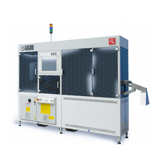
062AZ005A FEATURES FEATURES MACHINE DESCRIPTION The CHS family of machines control continuous plastic and aluminum cap quality. The caps are analyzed by a computerized inspection system (Control Vision System) and are transferred to the production cycle, if necessary. The CHS system can be applied to any type of machine that produces caps (new or already in operation) provided by any supplier, or it can be used as stand alone. -
Page 18: Spacer
062AZ005A FEATURES FIGURE 2.1.1/A - CHS100 MAIN DEVICES Base Air conditioner Spacer Personal computer Reject system Top guard (optional) Electrical cabinet Final diverter (optional) Control panel Bottom guard (optional) Monitor Conveyor belt Pneumatic system Inspection system Suction device T6865... - Page 19 062AZ005A FEATURES FIGURE 2.1.1/B - CHS200 MAIN DEVICES Base Personal computer Spacer Top guard (optional) Reject system Final diverter (optional) Electrical cabinet Bottom guard (optional) Control panel Standard conveyor belt Monitor Overturned conveyor belt Pneumatic system Top inspection system Suction device Bottom inspection system Air conditioner T6866...
- Page 20 062AZ005A FEATURES 2.1.1.1 Spacer The spacer consists of a spacing system of the caps on the belt slide surface. The double roller spacer is to be considered standard equipment; parts do not require to be replaced for cap size change. It may be replaced by the model with turn-plate which requires size related parts according to the cap to be inspected, shown in the figure TURN-PLATE SPACER (OPTIONAL) in this chapter.
- Page 21 062AZ005A FEATURES FIGURE 2.1.1.1/B - TURN-PLATE SPACER (OPTIONAL) Frame Motor Side guides Upper guide Side guide adjustment Upper guide adjustment Size related turn-plate Cover Size related side guide Guards Safety limit switch Flow stop piston Timing sensor T6867...
- Page 22 062AZ005A FEATURES FIGURE 2.1.1.1/C - TURN-PLATE SPACER WITH SPARK TESTER (OPTIONAL) Frame Motor Side guides Upper guide Side guide adjustment Upper guide adjustment Size related turn-plate Cover Size related side guide Guards Safety limit switch Flow stop piston Timing sensor Angle gear drive Spark tester turn-plate Turn-plate height adjustment...
-
Page 23: Spark Tester Device
062AZ005A FEATURES 2.1.1.2 SPARK TESTER device The SPARK TESTER device is used for checking the condition of caps made in thermoplastic material. The system allows the caps with defects that cannot be seen well to be identified with an optic control system, such as cameras. -
Page 24: Standard Conveyor Belt
062AZ005A FEATURES 2.1.1.3 Standard conveyor belt The standard conveyor belt 1 moves the spaced caps under the inspection system, then through a reject system 7 to the final diverter (optional), if necessary, for final boxing. The standard conveyor belt is provided in the CHS100 and in the first section of the CHS200 followed by the overturned conveyor belt (see paragraph OVERTURNED CONVEYOR BELT in this chapter). -
Page 25: Overturned Conveyor Belt
062AZ005A FEATURES 2.1.1.4 Overturned conveyor belt The overturned conveyor belt 1 picks up the spaced caps from an upstream conveyor belt and moves them under the inspection system, then through a reject system 7 for the selection, and then to the final diverter (optional), if necessary, for final boxing. -
Page 26: Electrical Cabinet
062AZ005A FEATURES 2.1.1.5 Electrical cabinet All information regarding the control panel is given in chapter 6 - OPERATING INSTRUCTIONS and in the INSTRUCTIONS B manual. 2.1.1.6 Pneumatic system The pneumatic system consists of a control unit 1 housed in the machine base and other parts found near the points of use to obtain top performance. -
Page 27: Diverter (Optional)
062AZ005A FEATURES 2.1.1.7 Diverter (optional) The diverter sends the caps to two different positions to permit box filling and box removal without causing the caps to fall out. FIGURE 2.1.1.7 - DIVERTER (OPTIONAL) Base coupling Exit outlet Compressed air coupling Cover T6872 2-11... -
Page 28: Top Inspection System
062AZ005A FEATURES 2.1.1.8 Top inspection system The top inspection system is installed in the CHS100 and in the first section of the CHS200; it is used for the inspection of the inside of the cap. A top inspection system can be installed in the CHS100 for checking the area outside the cap. -
Page 29: Bottom Inspection System
062AZ005A FEATURES 2.1.1.9 Bottom inspection system The bottom inspection system is installed in the second section of the CHS200; it is used for the inspection of the outside and of the side area of the cap. Images are acquired by a camera, while a led light illuminates them. The main defects that can be detected are: contamination scores/color changes... -
Page 30: 360° Inspection System (Optional)
062AZ005A FEATURES 2.1.1.10 360° inspection system (optional) The 360° inspection system is installed in the second section of the CHS200; it is used for the inspection of the external side walls of the cap. Images are acquired by four cameras, installed at 90° among them, by means of the led light of the bottom inspection system. -
Page 31: Intended, Prohibited And Misuse Of The Machine
UNINTENDED AND PROHIBITED OPERATIONS No other use is intended unless otherwise duly authorized by the manufacturer. SACMI will not be held responsible for any personal injury, equipment damage or malfunctions caused by use manners different from those specified in this manual. -
Page 32: Overall Dimensions
062AZ005A FEATURES OVERALL DIMENSIONS 2.2.1 CHS100 OVERALL DIMENSIONS FIGURE 2.2.1 - CHS100 OVERALL DIMENSIONS Air connection Material feed Electrical connection Work area T6888 1200 328.5 1807.5 2-16... -
Page 33: Chs200 Overall Dimensions
062AZ005A FEATURES 2.2.2 CHS200 OVERALL DIMENSIONS FIGURE 2.2.2 - CHS200 OVERALL DIMENSIONS Air connection Material feed Electrical connection Work area T6889 379.5 2400 3058.5 2-17... -
Page 34: Technical Features
062AZ005A FEATURES TECHNICAL FEATURES 2.3.1 CHS100/CHS200 TECHNICAL DATA Maximum production output pieces/min 3000 ELECTRICAL SYSTEM Installed power at 50 Hz (FULL OPTIONAL) 11.8 Power for cable dimensioning at 50 Hz Maximum absorbed power at 50 Hz Average absorbed power at 50 Hz PNEUMATIC SYSTEM Average consumption (at 0.5 Mpa) /min... -
Page 35: Acceptable Fluctuations For The Indicated Variables
Anno Year SACMI IMOLA S.C. V I A S E L I C E P R O V I N C I A L E 1 7 / A I M O L A - I T A L I A... - Page 36 Anno Year SACMI IMOLA S.C. V I A S E L I C E P R O V I N C I A L E 1 7 / A I M O L A - I T A L I A...
-
Page 37: Product Characteristics
062AZ005A FEATURES 2.3.5 PRODUCT CHARACTERISTICS TYPE OF PRODUCT The machine can control thermoplastic or aluminum caps with diameters between 18 mm and 50 mm and heights between 10 mm and 35 mm. Each cap format corresponds to an inspection system calibration adjustment as well as the appropriate adjustment of the spacing system. - Page 38 062AZ005A FEATURES FIGURE 2.3.5 - PRODUCT CHARACTERISTICS Ø 50 Ø 18 T6876 Maximum 3000 pieces/min The dimensions given in the figure are for reference purposes only and are not binding in any way. 2-22...
-
Page 39: Airborne Noise Level Emitted By The Machine
062AZ005A FEATURES 2.3.6 AIRBORNE NOISE LEVEL EMITTED BY THE MACHINE 2.3.6.1 CHS100 sound pressure level (EN ISO 11202) Measured values Test conditions Operating conditions: work cycle with no load. Type of processing: cap inspection. pC peak Operating cycle: cap inspection (1500 insp/min). dB(A) dB(C) Test environment: industrial factory with reflective floors. -
Page 40: Chs200 Sound Pressure Level
062AZ005A FEATURES 2.3.6.2 CHS200 sound pressure level (EN ISO 11202) Measured values Test conditions Operating conditions: work cycle with no load. Type of processing: cap inspection. pC peak Operating cycle: cap inspection (1500 insp/min). dB(A) dB(C) Test environment: industrial factory with reflective floors. 74.2 91.5 Values measured with load... -
Page 41: Data Sheet
Machine model Supplier's Supplier's Delivery date code order Production Date Test operator [pcs/min] SACMI machine equipment, Cap code Cap name CHS004 only Rated D Max. D (mm) H not folded H folded (mm) Cap slide surface height Second belt height (if provided) - Page 42 062AZ005A FEATURES Hardware key IMAGE SHOOTING "0" Camera Focus lens Light Camera cable IMAGE SHOOTING "1" Camera Focus lens Light Camera cable IMAGE SHOOTING "2" Camera Focus lens Light Camera cable IMAGE SHOOTING "3" Camera Focus lens Light Camera cable IMAGE SHOOTING "4"...
- Page 43 062AZ005A FEATURES External seria ports, Motherboard NOTES: Motor serial number, First conveyor belt Motor serial number, Second conveyor belt Motor serial number, Cap spacer Blower serial number, First conveyor belt Blower serial number, Second conveyor belt 1- INSTALLATION 2- START-UP 3- TEST 4- BACKUP 5- MANUALS...
-
Page 44: Diagrams
062AZ005A FEATURES DIAGRAMS 2.4.1 PNEUMATIC SYSTEM DIAGRAM FIGURE 2.4.1/A - CHS100 PNEUMATIC SYSTEM DIAGRAM Main shut-off valve Pressure switch YV1/2 Final diverter control Cap feed piston control YV13 Blower supply control YV30 SPARK TESTER reject/belt cleaning YV101 Reject YV102 Reject check Turn-plate spacer Final spacer Double roller spacer... - Page 45 062AZ005A FEATURES FIGURE 2.4.1/B - CHS200 PNEUMATIC SYSTEM DIAGRAM Main shut-off valve Pressure switch YV1/2 Final diverter control Cap feed piston control YV13 Blower supply control YV30 SPARK TESTER reject/belt cleaning YV101 Standard conveyor reject YV102 Control of standard conveyor reject YV103 Overturned conveyor reject YV104 Control of overturned conveyor reject Turn-plate spacer...
- Page 46 062AZ005A FEATURES FIGURE 2.4.1/C - LAYOUT OF ELEMENTS IN AIR SUPPLY SYSTEM Main shut-off valve Compressed air adjuster YV1/2 Diverter cylinder solenoid valve Solenoid valve, Cap spacer cylinder YV13 Solenoid valve, Blowers YV30 SPARK TESTER/belt cleaning solenoid valve YV101 Solenoid valve, Standard conveyor reject YV102 Solenoid valve, Standard conveyor reject control YV103 Solenoid valve, Overturned conveyor reject YV104 Solenoid valve, Overturned conveyor reject control...
- Page 47 062AZ005A FEATURES FIGURE 2.4.1/D - LAYOUT OF ELEMENTS IN AIR SUPPLY SYSTEM Main shut-off valve Compressed air adjuster YV1/2 Diverter cylinder solenoid valve Solenoid valve, Cap spacer cylinder YV13 Solenoid valve, Blowers YV30 SPARK TESTER/belt cleaning solenoid valve YV101 Solenoid valve, Standard conveyor reject YV102 Solenoid valve, Standard conveyor reject control YV103 Solenoid valve, Overturned conveyor reject YV104 Solenoid valve, Overturned conveyor reject control...
- Page 48 062AZ005A FEATURES 2-32...
-
Page 49: Safety Equipment And Precautions
Always take all necessary safety precautions and follow the guidelines when working on the machine. SACMI shall not be held responsible for any personal injury or property damage resulting from tampering or failure to use the safety devices provided. -
Page 50: Installed Safety Devices
WARNING! E0004 If SACMI does not supply the entire assembly which the machine is to be incorporated in, the end user is responsible for connecting the emergency shutdown circuit of the machine dealt with in this manual to the emergency shutdown circuit of the line in which it is installed. - Page 51 062AZ005A SAFETY EQUIPMENT AND PRECAUTIONS FIGURE 3.1.2/A - INSTALLED SAFETY DEVICES QS1 Main switch, Electrical cabinet SQ42 Interlocked microswitch Emergency stop button on control panel Fixed mechanical guards (optional) Indicator tower Mobile mechanical guards (optional) Double roller guards Turn-plate guards Belt safety devices Light guards Drive unit guards...
- Page 52 062AZ005A SAFETY EQUIPMENT AND PRECAUTIONS FIGURE 3.1.2/B - INSTALLED SAFETY DEVICES QS1 Main switch, Electrical cabinet SQ42 Interlocked microswitch Emergency stop button on control panel Fixed mechanical guards (optional) Indicator tower Mobile mechanical guards (optional) Double roller guards Turn-plate guards Belt safety devices Light guards Drive unit guards...
-
Page 53: Safety Rules For Handling
062AZ005A SAFETY EQUIPMENT AND PRECAUTIONS SAFETY RULES FOR HANDLING WARNING! E0004 Only specially trained authorized personnel may lift and handle the machine. No one should be near the hanging load or within the range of action of the lift equipment while the machine is being lifted and handled. -
Page 54: Using The Lift Equipment
062AZ005A SAFETY EQUIPMENT AND PRECAUTIONS 3.2.4 USING THE LIFT EQUIPMENT Use the lift equipment only in the manner specified in this manual. Hooking up the equipment or lifting in other ways may compromise the hook up points and the lift equipment, creating extremely dangerous situations for the operators. WARNING! E0004 Risk of being crushed at the points in which the equipment is attached when hoisting the load. -
Page 55: Installation
If electronic converters are present in the electrical control cabinet, the differential protective devices installed on the cabinet’s power supply line must ensure protection against leakage currents. WARNING! E0004 SACMI shall not be held responsible for any property damage or personal injury resulting from improper installation. -
Page 56: Operator Training
062AZ005A SAFETY EQUIPMENT AND PRECAUTIONS OPERATOR TRAINING WARNING! E0004 3.4.1 COMPANY USING THE MACHINE The machine is designed for professional use. The company using the machine must prevent access by unauthorized personnel. The company using this equipment must see that their personnel: read and understand the manual in its entirety;... - Page 57 062AZ005A SAFETY EQUIPMENT AND PRECAUTIONS FIGURE 3.4.2/A - OPERATOR'S WORK POSITION IN CHS100 T6890 FIGURE 3.4.2/B - OPERATOR'S WORK POSITION IN CHS200 T6891...
-
Page 58: The Maintenance Worker
062AZ005A SAFETY EQUIPMENT AND PRECAUTIONS 3.4.3 THE MAINTENANCE WORKER The maintenance staff must be selected according to the same criteria as that indicated for the operators. In addition, they must be trained in specific technological areas (mechanical, electric, pneumatic, etc.) so that they can carry out the operations they are responsible for (as specified in the manual) in complete safety using suitable tools and equipment. -
Page 59: Operation, Adjustments And Maintenance
E0004 Only SACMI genuine spare parts may be used. If the customer uses safety components (tubes, interlocks, switches, etc.) supplied by other manufacturers or does not install them correctly, SACMI shall no longer be held responsible for safe machine operation. - Page 60 WARNING! E0004 SACMI shall not be held liable for any personal injury or property damage and all warranties shall be void if: spare parts different from those initially installed in the machine are used; spare parts are incorrectly installed;...
- Page 61 062AZ005A SAFETY EQUIPMENT AND PRECAUTIONS WARNING! E0004 Never use the machine if any of the safety devices are malfunctioning under any circumstances. Immediately shutdown the machine cutting off all the power sources. Start the machine only after all the safety devices function efficiently. WARNING! E0004 If breathable dust forms while cleaning the machine, wear a protective mask and adequately air out the room.
-
Page 62: Lights: Residual Risks From Light Discharge
062AZ005A SAFETY EQUIPMENT AND PRECAUTIONS 3.5.2 OPERATION, ADJUSTMENTS AND MAINTENANCE 3.5.2.1 Lights: residual risks from light discharge WARNING! E0004 Strong flashes are emitted while the lights are running. If the light is looked at directly, the retina may be permanently damaged. 3.5.2.2 Access to the machine through the cap exit area WARNING! -
Page 63: Safety Guards With Mechanical Lock
062AZ005A SAFETY EQUIPMENT AND PRECAUTIONS 3.5.2.3 Safety guards with mechanical lock A number of safety guards with mechanical locks may stay in place even without the fixing screws, for example the cover of the turn-plate spacer. WARNING! E0004 Always secure all the safety guards in place before attempting to start up the machine. 3.5.2.4 Pneumatic drive risks Before operating on the machine, cut off the pneumatic system from the supply mains by locking the main shutoff... -
Page 64: Risks From Excessive Air Pressure
062AZ005A SAFETY EQUIPMENT AND PRECAUTIONS 3.5.2.5 Risks from excessive air pressure WARNING! E0004 It is severely forbidden to modify the pressure relief devices that protect the air system. Incorrectly adjusting these devices may cause malfunctions or break downs in the pneumatic system creating hazardous conditions for personnel. -
Page 65: Decommissioning And Dismantling The Machine
Use only adequate lift means and equipment that comply with current regulations and standards. WARNING! E0004 If the machine has to be moved from one factory to another, contact SACMI Technical Service to obtain information about packing and shipment. 3-17... -
Page 66: Dismantling
062AZ005A SAFETY EQUIPMENT AND PRECAUTIONS 3.6.2 DISMANTLING WARNING! E0004 Follow the instructions given in Chapter 9 - DISMANTLING paragraph DISMANTLING and observe current standards and safety regulations. WARNING! E0004 Only skilled personnel properly trained on how to work on and handle the machine are authorized to dismantle it. Use only adequate lift means and equipment that comply with current regulations and standards. -
Page 67: Installation
062AZ005A INSTALLATION INSTALLATION SHIPPING AND HANDLING The machine will be delivered to the customer already pre-assembled in one unit. Only a fork lift truck can be used for lifting, as indicated in the figure. FIGURE 4.1/A - SHIPPING AND HANDLING CHS100 WEIGHT 350 kg T6882 FIGURE 4.1/B - SHIPPING AND HANDLING CHS200... -
Page 68: Machine Blocks
The best systems for lifting and handling the heaviest and largest parts as well as those that require special care and tools provided by SACMI are shown in the figure. When lifting the smaller parts and packages, be careful and use the most suitable equipment observing the safety precautions. -
Page 69: Assembling The Machine (Chs100/Chs200)
062AZ005A INSTALLATION ASSEMBLING THE MACHINE (CHS100/CHS200) Position the machine 1. Level machine 1 with the adjustable height threaded legs 2. Install the indicator tower 3. Place the SPARK TESTER electrical cabinet 5 next to the turn-plate spacer with SPARK TESTER 4. FIGURE 4.2/A - ASSEMBLING THE MACHINE (CHS100/CHS200) Machine Threaded feet... - Page 70 062AZ005A INSTALLATION FIGURE 4.2/B - ASSEMBLING THE MACHINE (CHS100/CHS200) Machine Threaded feet Indicator tower SPARK TESTER device SPARK TESTER electrical cabinet T6911 T5712...
-
Page 71: Connections
062AZ005A INSTALLATION CONNECTIONS Only properly trained personnel are authorized to hook the machine up to the various power sources. 4.3.1 CONNECTION TO THE PNEUMATIC SYSTEM PNEUMATIC CONTROL UNIT Connect a hose with internal diameter as indicated in the specifications running from the compressed air mains supply to fitting A. -
Page 72: Electrical Connection
062AZ005A INSTALLATION 4.3.2 ELECTRICAL CONNECTION The customer must assure the machine is connected to an electrical system equipped with a device that protects against surges. The cut off current must be suitable to protect the supply wires. WARNING! E0004 As there are a number of electronic converters inside the electrical cabinet, make sure the ground fault circuit interrupters on the power supply line are of the B type (as recommended by CEI 64-8 specifications, art. -
Page 73: Connecting The Electric Cables
062AZ005A INSTALLATION 4.3.2.1 Connecting the electric cables Connect the supply cable A to the company mains. WARNING! E0004 Failure to ground the machine may cause serious personal injury as well as equipment damage. Unless otherwise specified, the connections are to be made by the installation worker appointed by the customer. The power and ground cables should have an adequate cross-section and be constructed so that they are suitable for the specific wiring system. - Page 74 062AZ005A INSTALLATION FIGURE 4.3.2.1/B - CONNECTING THE SPARK TESTER DEVICE ELECTRIC CABLES...
-
Page 75: Ground Connection
062AZ005A INSTALLATION 4.3.2.2 Ground connection Connect the points marked with symbol (417-IEC-5019) directly to an efficient ground system. E0006 Only specially trained personnel are authorized to make the connections in the areas specified on the relative nameplates. Before tightening the clamp screws provided, remove any paint from the press body at the points where the ground conductors are connected. - Page 76 062AZ005A INSTALLATION 4-10...
-
Page 77: Start-Up
Check operation of the audible/visual indicators. WARNING! E0004 SACMI shall not be held liable for any personal injury or property damage and all warranties shall be void if: spare parts different from those initially installed in the machine are used; spare parts are incorrectly installed;... -
Page 78: Operation Check
062AZ005A START-UP 5.2.2 OPERATION CHECK Refer to the INSTRUCTIONS B manual for directions on how to set the operating parameters described in this paragraph. Activate the main switch on the main electrical cabinet: look at the screen to make sure the PC start-up operations are correct and that no warning or error messages appear. -
Page 79: Operating Instructions
062AZ005A OPERATING INSTRUCTIONS OPERATING INSTRUCTIONS OPERATOR INTERFACE The control panel and touch screen monitor are used for controlling machine operations. WARNING! E0004 All the instructions for programming and operating the controller are provided in the INSTRUCTIONS B manual. The background colors and colors of the keys may vary according to the electric codes in force in the country of installation. -
Page 80: Indicator Tower
062AZ005A OPERATING INSTRUCTIONS 6.1.2 INDICATOR TOWER The indicator tower indicates the operating condition of the machine. 1 Orange: machine stopped. 2 Blue: machine and/or CVS faulty. 3 Green: operating condition. FIGURE 6.1.2 - INDICATOR TOWER T6909... -
Page 81: Spark Tester Device Operator Interface
062AZ005A OPERATING INSTRUCTIONS 6.1.3 SPARK TESTER DEVICE OPERATOR INTERFACE The operator interface is the SPARK TESTER equipment, on which the following operations can be performed: the operating voltage can be set the operating data can be entered or changed even when the work-cycle is in progress. WARNING! E0004 All the instructions for programming and operating the controller are provided in the INSTRUCTIONS B manual. -
Page 82: Work Cycles
062AZ005A OPERATING INSTRUCTIONS WORK CYCLES (References in figure CHS OPERATOR INTERFACE in this chapter) 6.2.1 WORK CYCLE IN MANUAL MODE Operations in MANUAL mode must only be performed during the adjustment and/or diagnostics phases to analyze individual operations. The operators must pay special attention when performing these operations. The mode selector 8 must be turned to MANUAL. -
Page 83: Cycle With Modifications Made To The Software Configuration And Image Shooting Station
062AZ005A OPERATING INSTRUCTIONS 6.2.2.3 Cycle with modifications made to the software configuration and image shooting station This type of start-up implies that the software configuration from the last shut off must be changed as well as the adjustments for the image shooting and conveyor stations. This is the case in which a production change is made with a different mechanical format of the pieces to be inspected. -
Page 84: Machine Stoppage
062AZ005A OPERATING INSTRUCTIONS MACHINE STOPPAGE (References in figure CHS OPERATOR INTERFACE in this chapter) 6.3.1 SHUTDOWN DURING OPERATION Press the stop button 4. Turn the main switch 9 to the OFF position. If the power supply needs to be cut off from the machine, wait for the computer shut off procedure to finish. 6.3.2 EMERGENCY STOP The emergency stop must only be used in emergency conditions. -
Page 85: Adjustments
062AZ005A ADJUSTMENTS ADJUSTMENTS ADJUSTING THE VISION SYSTEM 7.1.1 PROCEDURE FOR CHECKING THE ACQUISITION AND EJECTION DEVICES This procedure is carried out to verify the sensor/encoder and reject device work correctly. Prepare ten pieces (they can be good quality or defective pieces). Open the tracking/reject parameter window. -
Page 86: Procedure For Inspecting Products
062AZ005A ADJUSTMENTS 7.1.3 PROCEDURE FOR INSPECTING PRODUCTS The following are needed to carry out the test procedure for the product in question: at least ten samples of each defect the vision system has to detect and reject; at least one hundred good quality sample pieces, in any case more good quality samples have to be provided than defective ones. -
Page 87: Pneumatic System Adjustment
062AZ005A ADJUSTMENTS PNEUMATIC SYSTEM ADJUSTMENT The air flow rate of the blowers that move the caps in the channels can be adjusted using the relative adjusters found in the blowers. Adjust the blowers according to necessity. The operating pressure is indicated in paragraph TECHNICAL DATA in chapter 2 - FEATURES of this manual. 7.2.1 PNEUMATIC CONTROL UNIT ADJUSTMENTS FIGURE 7.2.1 - PNEUMATIC CONTROL UNIT ADJUSTMENTS... -
Page 88: Pressure Adjustment
062AZ005A ADJUSTMENTS 7.2.2 PRESSURE ADJUSTMENT Release the knob 7 by pulling it out. Turn adjustment knob 7 until gauge 9 reads the desired pressure setting. When the adjustment has been made, push the knob fully in to lock it in place. 7.2.3 PRESSURE SWITCH SETTING Release the knob 8 by pulling it out. -
Page 89: Size Changeover Procedures
062AZ005A ADJUSTMENTS SIZE CHANGEOVER PROCEDURES When the cap format to be analyzed is changed, the following mechanical adjustments must be made/checked to allow correct cap operation. 7.3.1 ADJUSTING THE 2-WHEEL SPACER Loosen the fixing screws 1 and work on the adjustment screws 2 to loosen the reference nuts. Place the lower surface 3 of the side guide at +0.5 mm in relation to the surface of the cap slide belt. -
Page 90: Adjusting The Turn-Plate Spacer
062AZ005A ADJUSTMENTS 7.3.2 ADJUSTING THE TURN-PLATE SPACER Loosen the fixing screws 1 and work on the adjustment screws 2 to loosen the reference nuts. Place the cap slide plate 3 at +0.5 mm in relation to the conveyor belt 4. Loosen the screws 5 and the clamps 6 and place one cap at the beginning and one cap at the end of the guides. -
Page 91: Adjusting Cylinder Yv3 And Timing Sensor Sq6 In The Turn-Plate Spacer
062AZ005A ADJUSTMENTS 7.3.3 ADJUSTING CYLINDER YV3 AND TIMING SENSOR SQ6 IN THE TURN-PLATE SPACER Loosen the screws of the pneumatic cylinder support 1. Lay the cap 2 immediately after the tip of the turn-plate 3. The piston 4 of the pneumatic cylinder YV3 should stop the cap without tolerance in the tangency point of the cap 2 with the turn-plate 3. - Page 92 062AZ005A ADJUSTMENTS FIGURE 7.3.3 - ADJUSTING CYLINDER YV3 AND TIMING SENSOR SQ6 IN THE TURN-PLATE SPACER Pneumatic cylinder YV3 support Turn-plate (size related) Pneumatic cylinder YV3 piston Tightening bolt SQ6 Turn-plate for sensor SQ6 TANGENCY POINT FOR READING START T6895...
-
Page 93: Adjusting The Spark Tester Turn-Plate
062AZ005A ADJUSTMENTS 7.3.4 ADJUSTING THE SPARK TESTER TURN-PLATE The distance between the bottom of the cap 4 and the tip of the turn-plate 3 should not be greater than 1 mm. To do this, loosen the fixing screws 1 and remove the shims 2 if required. After the distance has been found, secure the screws 1. -
Page 94: Adjusting The Blowers For The Solenoid Valve And Sensors On The Conveyor Belt
062AZ005A ADJUSTMENTS 7.3.5 ADJUSTING THE BLOWERS FOR THE SOLENOID VALVE AND SENSORS ON THE CONVEYOR BELT Loosen the fixing screws 1 and bring the reject nozzle 2 to 5 mm from the cap to be rejected (dimension recommended and referred to the cap centered on the belt). Tighten the fixing screws. -
Page 95: Adjusting The Overturned Conveyor Belt (Chs200)
062AZ005A ADJUSTMENTS 7.3.6 ADJUSTING THE OVERTURNED CONVEYOR BELT (CHS200) Loosen the screw 1 of the belt connecting unit 2. Loosen the screws 3 of the supporting unit for the overturned belt 4. Adjust the height of the overturned belt support with the screw 5. Leave a clearance of 1-1.5 mm between the cap and the belt with shims. - Page 96 062AZ005A ADJUSTMENTS FIGURE 7.3.6/B - ADJUSTING THE OVERTURNED CONVEYOR BELT (CHS200) Screw Belt connection Screws Belt support Adjustment screw T6898 7-12...
-
Page 97: Adjusting The Final Diverter (Optional)
062AZ005A ADJUSTMENTS 7.3.7 ADJUSTING THE FINAL DIVERTER (OPTIONAL) Use the pressure adjustment valve 1 to control the cap deflector 2 and prevent it from hitting the end stop too hard. The movement should be soft and regular in both directions. FIGURE 7.3.7 - ADJUSTING THE FINAL DIVERTER (OPTIONAL) Pressure adjustment valve Cap deflector... - Page 98 062AZ005A ADJUSTMENTS FIGURE 7.3.8/B - ADJUSTING THE CAP SLIDE PLATE Key outlet T6901 Loosen the nut 1. Use the key outlet 2 to raise or lower the machine. Check the cap slide plate with a spirit level so that the machine is perfectly level. Tighten the nut 1.
-
Page 99: Adjusting The Reject Conveyor
062AZ005A ADJUSTMENTS 7.3.9 ADJUSTING THE REJECT CONVEYOR Loosen the screws 1 of the reject conveyor unit 2 so as to adjust the height considering the path of the cap rejected by the solenoid valve. Loosen also the screws 3 that adjust the rubber band 4. Adjust the band so that the rejected cap hits it along the path. -
Page 100: Replacing The Sensors
062AZ005A ADJUSTMENTS 7.3.10 REPLACING THE SENSORS FIGURE 7.3.10 - REPLACING THE SENSORS SQ42 T6903 SQ53/SQ101 SQ102 SQ11 SQ53B/SQ103 SQ104 SQ11B 7-16... - Page 101 062AZ005A ADJUSTMENTS DISTANCE X SENSOR REFERENCE OBJECT (mm) 0.5-1 (see paragraph ADJUSTING CYLINDER Turn-plate/piston timing sensor YV3 AND TIMING SENSOR SQ6 IN THE TURN-PLATE SPACER) PHOTOCELLS WITH DISTANCE X REFERENCE OBJECT REFLECTOR (mm) Minimum level cap feed channel Maximum level cap feed channel SQ53/SQ101 Check caps entering belt 1...
-
Page 102: Adjusting The Image Capture
062AZ005A ADJUSTMENTS 7.3.11 ADJUSTING THE IMAGE CAPTURE Adjust light support 1 positioning. The height among the lights and the cap slide plate must be the same as the height of the cap to be inspected plus 5 mm. Adjust camera support 2 positioning. Make sure the diameter of the cap to be inspected framed by the camera is equal to 80%±1% of the shortest side of the acquisition frame. -
Page 103: Maintenance
WARNING! E0004 SACMI shall not be held liable for any personal injury or property damage and all warranties shall be void if: spare parts different from those initially installed in the machine are used; spare parts are incorrectly installed;... -
Page 104: Routine Maintenance
062AZ005A MAINTENANCE ROUTINE MAINTENANCE 8.1.1 ROUTINE MAINTENANCE TABLE... - Page 105 062AZ005A MAINTENANCE...
-
Page 106: Routine Maintenance Operations
062AZ005A MAINTENANCE 8.1.2 ROUTINE MAINTENANCE OPERATIONS 8.1.2.1 Cleaning of the lenses, focus lenses and mirrors Dust or extraneous matter that build up may compromise system efficiency. Clean the lenses and mirrors with purified non-lubricated air to remove impurities, and then soft wipes. WARNING! E0004 Make sure not to change any of the camera adjustments or positions while cleaning them. -
Page 107: Conveyor Belt Tensioning
062AZ005A MAINTENANCE 8.1.2.3 Conveyor belt tensioning Check for tensioning and centering if a malfunction in the conveyor belts is found. Make sure the suction holes are overlapped to the suction slots for checking belt centering. Remove the guard 3 and loosen the lock nuts 2. Work on the adjustment screws 1 and dowels 4. Proper tightening is when the belt can be raised with one hand by approximately ten centimeters without excessive effort. -
Page 108: Replacing The Belt
062AZ005A MAINTENANCE 8.1.2.4 Replacing the belt Loosen the dowels 17 and remove the encoder 6. Loosen the screws 1 and remove the cover 2. Loosen the nuts 3 and loosen the screws 4 to easily remove the belt 5. Loosen the screw 7. Loosen the screws 8 and remove the plate 9. - Page 109 062AZ005A MAINTENANCE FIGURE 8.1.2.4/B - REPLACING THE BELT Screw Guard Screw Belt Encoder Screw Screw Plate Screw Protective panel Screw Protective panel Protective panel Air hose coupling Solenoid valve connector Dowels T6906...
-
Page 110: Cleaning/Replacing The Pneumatic System Filter
062AZ005A MAINTENANCE 8.1.2.5 Cleaning/replacing the pneumatic system filter Take off the cover 13. Take out the filter cartridge and clean or replace it, if necessary. Clean the filter slot and the part inside the cover. Insert the filter. Remount the cover 13. WARNING! E0004 The cover should be tightened to a torque not greater than 6 Nm in order not to damage it. -
Page 111: Cleaning The Electrical Cabinet And Electrical Cabinet Fans
062AZ005A MAINTENANCE 8.1.2.6 Cleaning the electrical cabinet and electrical cabinet fans Clean the components inside the electrical cabinets with a suction device (do not use compressed air jets). Check and tighten the terminal blocks, bolts and connectors, if necessary. FIGURE 8.1.2.6 - CLEANING THE ELECTRICAL CABINET AND ELECTRICAL CABINET FANS T5712 8.1.2.7 Checking operation of the SPARK TESTER device brush... -
Page 112: Check Operation Of The Safety Microswitch Sq42 In The Turn-Plate Spacer
062AZ005A MAINTENANCE 8.1.2.8 Check operation of the safety microswitch SQ42 in the turn-plate spacer Turn on the machine with the main switch. Press key RESET to reset the machine. Open the cover of the microswitch and make sure power supply is not uninterrupted in normally closed contacts with an electric multitester. -
Page 113: Torques (Nuts & Bolts)
062AZ005A MAINTENANCE TORQUES (NUTS & BOLTS) S.R. = Resisting cross section = Tightening torque = Pre-charge WARNING! E0004 12.9 class screws must be tightened with a torque wrench. The operation must be done as if they were of the 10.9 class. Example: a 12 mm dia. -
Page 114: Trouble-Shooting
062AZ005A MAINTENANCE TROUBLE-SHOOTING 8.4.1 TROUBLE-SHOOTING FOR THE MACHINE PROBLEM CAUSE REMEDY Turn-plate spacer: There are deformed caps in the Remove any deformed caps. caps jammed. channel. Conveyor belt: Plastic build-ups that obstruct the Clean the slots of the slide surface caps unstable. - Page 115 Close the machine and electrical cabinet doors to prevent damage from tampering and dust from getting in. WARNING! E0004 If the machine has to be moved from one factory to another, contact SACMI Technical Service to obtain information about packing and shipment.
- Page 116 062AZ005A DISMANTLING DISMANTLING WARNING! E0004 Only skilled personnel properly trained on how to work on and handle the machine are authorized to dismantle it. Use only adequate lift means and equipment that comply with current regulations and standards. If the machine is to be dismantled, first of all, make it in operative as instructed below: Use the factory main switch to cut off electrical power to the machine.
Need help?
Do you have a question about the Imola CHS Series and is the answer not in the manual?
Questions and answers