Table of Contents
Advertisement
VAULT COPY
INTRODUCTION
Chapters
1. Operation
2. Theory of Operation
Rev AB.1 is available in Vault-PM on Voyager
3. Specifications
4. Repair Information
5. Schematics
6. Parts
7. Calibration
8. Preventive Maintenance
A complete, detailed table of contents begins on page iii. Also, on the first page of each
chapter a table of contents for that chapter is provided.
FOREWORD
This Service Manual (P/N 0070-00-0429) is intended as a guide, for technically qualified
personnel, to use during repair and calibration procedures for the Accutorr Plus (part
number 0998-00-0444-XX). NOTE: See the serial number label on the rear panel of the
unit for part number identification. This manual also includes information on the Recorder
and Predictive Temperature Modules.
The information in this manual has been divided into the eight chapters listed above.
This publication may have been updated to reflect product design changes and/or manual
improvements. Any such changes to this manual would be accomplished by supplying
replacement pages and instructions for inserting or affixing them into the manual.
NOTE
Unauthorized servicing may void the remainder of the warranty. Check with the
factory or with a local authorized Datascope representative to determine the
warranty status of a particular instrument.
NOTE: This product is year 2000 compliant.
Copyright © Datascope Corp., 1999. Printed in U.S.A. All rights reserved. Contents of this
publication may not be reproduced in any form without permission of Datascope Corp.
Accutorr Plus, Service Manual
i
Chapter 1 - Operation
Advertisement
Table of Contents
Troubleshooting

Related Manuals for Datascope Accutorr Plus


Summary of Contents for Datascope Accutorr Plus
- Page 1 This Service Manual (P/N 0070-00-0429) is intended as a guide, for technically qualified personnel, to use during repair and calibration procedures for the Accutorr Plus (part number 0998-00-0444-XX). NOTE: See the serial number label on the rear panel of the unit for part number identification.
- Page 2 This page intentionally left blank. Accutorr Plus, Service Manual Chapter 1 - Operation...
-
Page 3: Table Of Contents
1.3.6.2 To View the Stored Measurements on the Accutorr Plus NIBP with Trend Screen and the Accutorr Plus NIBP with Trend Screen and SpO ....1-29... - Page 4 1.3.6.3 To Delete the Stored Measurements on all Models of the Accutorr Plus ..... 1-29 1.3.7 Setting the Alarm Volume and Beep Volume ..1-30 1.3.8...
- Page 5 ........4-13 4.6.16 AccuTemp IR Mounting Cradle ....4-13 Accutorr Plus Service Manual Revised 12/20/00 Introduction...
- Page 6 6.8 Isometric Drawings and Parts List ......6-5 6.8.1 Accutorr Plus Isometric Parts List (All Models) ..6-5 6.8.2 Recorder Module Isometric Parts List .
- Page 7 Low Battery Sensing ......7-17 7.7 Battery Test for Accutorr Plus ......7-18 7.7.1...
- Page 8 This page intentionally left blank. viii Accutorr Plus Service Manual Introduction...
-
Page 9: Introduction
1.1 INTRODUCTION This section of the Service Manual (P/N 0070-00-0429) is provided as a review of the Accutorr Plus NIBP, the Accutorr Plus NIBP with Trend Screen and the Accutorr Plus NIBP with Trend Screen and SpO functions and operation. The reader is encouraged to refer to the Operating Instructions, P/N 0070-00-0428, for more complete details. - Page 10 This page intentionally left blank. Accutorr Plus, Service Manual Chapter 1 - Operation...
-
Page 11: Controls And Indicators
1.2 CONTROLS AND INDICATORS This section of the Service Manual identifies and describes each control and display of the Datascope Accutorr Plus NIBP, the Accutorr Plus NIBP with Trend Screen and the Accutorr Plus NIBP with Trend Screen and SpO . -
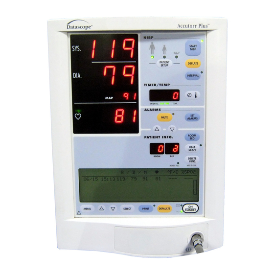
Page 12: Front Panel
123/61 98.5 02:35 20/05 127/62 97.6 20/05 02:33 185/105 ---- 20/05 02:30 98.2 129/62 MENU SELECT PRINT DEFAULTS STANDBY Figure 1-1 Front Panel - Accutorr Plus NIBP with Trend Screen and Datascope SpO Accutorr Plus Service Manual Chapter 1, Operation... - Page 13 20/05 02:33 185/105 ---- 20/05 02:30 98.2 129/62 MENU SELECT PRINT DEFAULTS STANDBY Nellcor Figure 1-2 Front Panel - Accutorr Plus NIBP with Trend Screen and Nellcor or Masimo SpO ® Accutorr Plus Service Manual Revised 02/15/00 Chapter 1, Operation...
- Page 16 %SpO alarm limits. 7. Liquid Crystal Display (LCD) (Accutorr Plus models with Trend Screen) The Liquid Crystal Display (LCD) is used to display previous measurements (trend list) for the selected patient, or a menu that controls the beep volume and alarm volume.
- Page 17 LED will flash when the battery requires charging. When the LED begins flashing, approximately 30 minutes of battery time remain on the Accutorr Plus NIBP (20 minutes on the Accutorr Plus NIBP with Trend Screen and 10 minutes on the Accutorr Plus NIBP with Trend Screen and SpO 18.
- Page 18 On all models of the Accutorr Plus, press and hold this key (2 beep tones, approx. 6 seconds) to scan all of the rooms and beds for stored measurements. Press the Data Scan key again to stop on a particular room/bed.
- Page 19 This key is used to switch between viewing the elapsed time or the temperature in the Interval/Elap. Time/Temp Display. When viewing stored measurements on the Accutorr Plus NIBP, press this key to switch between viewing the temperature and time of the measurement.
- Page 20 To enter the Service Diagnostics mode, press and hold this key (1 beep tone) while the Accutorr Plus is powering on and running the self tests (all “8"’s displayed in the LEDs). The Service Diagnostics mode is used to initiate various performance tests that are to be done by technical service personnel only.
-
Page 21: Rear Panel
46. Datascope Connector Used by Datascope Technical Service Personnel. 47. Pole Mounting Handle and Cam Provides the ability to quickly mount the Accutorr Plus to a rolling pole. 48. Recorder Module Connector Used to connect the optional Datascope recorder module. -
Page 22: Predictive Thermometer Module
Used to store a box of probe covers. 50. Probe Chamber Used to store the temperature probe when not in use. 51. Probe Connector Used to connect the thermometer probe to the PTM module. 1-14 Accutorr Plus Service Manual Chapter 1, Operation... -
Page 23: Recorder Module
53. Paper Tear Edge The paper tear edge is used to tear off printed recorder strips. The edge can be removed in the event of a paper jam that needs to be cleared. Accutorr Plus Service Manual 1-15 Chapter 1, Operation... - Page 24 This page intentionally left blank. 1-16 Accutorr Plus Service Manual Chapter 1, Operation...
-
Page 25: Operation
. The numbers in parentheses ( ) refer to the items described in Section 1.2, “Controls and Indicators”. When a described feature refers to a particular model, it will be noted. When the name Accutorr Plus is used, it refers to all 5 models. 1.3.1 SETTING-UP / TURNING POWER ON 1. -
Page 26: Patient Setup And Room/Bed Assignment
The initial cuff inflation pressure depends on the Patient Size setting. The initial cuff inflation pressures are listed in the table below. The initial cuff inflation pressures can be modified from the default (custom or factory) settings. When the Accutorr Plus is powered down, these modifications are deleted. -
Page 27: Room Number And Bed Letter
Once measurements have been taken, and the unit is powered off and on, the room number and bed letter will default to the lowest room and bed where data is currently stored. Accutorr Plus Service Manual 1-19 Chapter 1, Operation... -
Page 28: Manual Nibp Measurements And General Nibp Measurement Information
The table above indicates the available Datascope cuffs for use with the Accutorr Plus. The design dimensions of the cuffs and their intended uses are based on recommendations of the American Heart Association. - Page 29 6. When required, press the DEFLATE key (36) to interrupt a measurement. The cuff will deflate. NOTE: Once the initial measurement is taken for a room/bed, the Accutorr Plus will continue to use the selected patient size. NOTE: Check the patient’s limb for any indications of circulation impairment.
-
Page 30: Nibp Pressure Limit Fail Safe
It is also pos si ble to per ma nently over ride this ad just ment in the User Con fig u ra tion. See sec tion 1.3.15 for de tails. 1-22 Accutorr Plus Service Manual Re vised 05/22/02 Chapter 1, Operation... -
Page 31: Automatic Nibp Measurements (Interval Mode)
AUTOMATIC NIBP MEASUREMENTS (Interval Mode) The Accutorr Plus can be set to au to mat i cally take NIBP mea sure ments. On ini tial power up, the in ter val set ting will de fault to OFF. The User Con fig u ra tion mode can be used to set cus tom de faults for the In ter val Mode. -
Page 32: Changing The Interval Setting
(interval indicator flashes) until the NIBP Start key is pressed. 1.3.4.2 Changing the Interval Setting If the interval time is changed while the Accutorr Plus is in the interval mode, the new interval time is used once it is entered. For example: The interval time is set to 60 minutes. -
Page 33: Alarms
HI and SpO LO. When all of the available parameters have been selected, the next press of the SET ALARMS key returns the Accutorr Plus to normal operation. 2. To change an alarm limit setting, use the Patient Info. Up & Down Arrow keys (27 &... -
Page 34: Alarm Violations
· The LEDs for the parameter in an alarm condition flashes. · The parameter in an alarm condition is in reverse video on the LCD (Accutorr Plus models with Trend Screen). · The alarm tone is sounded (unless muted with the MUTE key (30)). -
Page 35: How To Mute Alarms
PRE CAU TION: It is the us ers re spon si bil ity, when chang ing the room/bed, to as sure the pa tient size and alarm set tings are as re quired. Accutorr Plus Service Manual 1-27 Re vised 05/22/02... -
Page 36: To View And Delete Stored Data (Trend Mode)
The Accutorr Plus NIBP uses the Systolic, Diastolic, MAP, and Temp displays to view stored data. The Accutorr Plus models with Trend Screen use the LCD to display up to 5 measurements at a time. The stored data that is viewed is for the currently selected patient (indicated by the room number/bed letter). -
Page 37: To View The Stored Measurements On The Accutorr Plus Nibp With Trend Screen And The Accutorr Plus Nibp With Trend Screen And Spo
(21) (2 beep tones, approx. 6 seconds) to delete all stored measurements for the current patient. When all data is cleared the patient size will be the default selection. 5. On the Accutorr Plus NIBP only, press the DATA SCAN key (22) (1 beep tone) to exit the delete data mode. -
Page 38: Setting The Alarm Volume And Beep Volume
SETTING THE ALARM VOLUME AND BEEP VOLUME The LCD on the Accutorr Plus mod els with Trend Screen is used to dis play the Trend List as de scribed in sec tion 1.3.6. It is also used to dis play a menu which is used to set the alarm vol ume and the SpO beep vol ume. -
Page 39: Setting The Lcd Contrast (View Angle Adjustment)
1.3.8 SETTING THE LCD CONTRAST (View Angle Adjustment) The LCD on the Accutorr Plus models with Trend Screen can be adjusted for optimum viewing. The MENU key (8) and the LCD Up and Down Arrow keys (9 & 10) are used to adjust the contrast. -
Page 40: Display Time Out Mode
3 and 15 minutes. The LED display time out can be set between 5 and 60 minutes. Since the Accutorr Plus can be powered from either an AC or DC source, the user configuration allows the setting of separate times for each type of power source. -
Page 41: Spo 2 Measurements (Accutorr Plus Model With Spo 2 )
1.3.10.1 Datascope Pulse Oximetry Sensors A. Introduction A wide range of Datascope sensors are available for connection to the Accutorr Plus model with SpO . The sensors cover both short-term and long-term monitoring needs on patients ranging from infants to large adults. - Page 42 Rejection of Ambient Light - Many monitoring situations involve high levels of ambient light, i.e.., operating room lights, neonatal phototherapy, heat warmers, etc. The Accutorr Plus model with SpO , the sensors, and the bandages each contribute to the rejection of ambient light. The monitor automatically measures and corrects for high levels of ambient light.
- Page 43 C. Sensor Connection to the Accutorr Plus model with SpO 1. Align the cable connector on the sensor assembly with the SpO Connector (15) on the Accutorr Plus model with SpO 2. Push the cable connector into the SpO Connector (15). Confirm that the cable connector is securely in place.
- Page 44 * <Non-adhesive bandages are recommended for premature infants to minimize prenatal skin damage. ** See Accessories, Chapter 5, for more detailed information. *** Additional choices: 0060-00-0026-02 (10’ sensor cable), 0020-00-0071-01 (3’ sensor cable plus 7’ extension cable). 1-36 Accutorr Plus Service Manual Revised 02/15/00 Chapter 1, Operation...
-
Page 45: Sequence For Establishing Spo
Carefully read the sensor directions for use, the Accutorr Plus operating instructions, and all precautionary information before use. - Page 46 ® relatively poor. For low peripheral perfusion, consider using the NELLCOR RS-10 reflectance oxygen transducer, which is applied to the forehead or temple. 1-38 Accutorr Plus Service Manual Revised 02/15/00 Chapter 1, Operation...
- Page 47 LED is determined and encoded into a calibration resistor in the sensor plug. The instrument’s software reads this calibration resistor to determine the appropriate calibration coefficients for the measurements obtained by that sensor. Accutorr Plus Service Manual 1-39 Revised 02/15/00...
-
Page 48: Sequence For Establishing Spo
Carefully read the sensor directions for use, the Accutorr Plus operating instructions, and all precautionary information before use. - Page 49 The adhesive can be partially rejuvenated by wiping with an alcohol wipe and allowing the sensor to thoroughly air dry prior to replacement on the patient. Accutorr Plus Service Manual 1-41 Revised 06/19/01...
- Page 50 E. Oximetry Sensitivity Mode and Post Averaging Time The Accutorr Plus sensitivity mode for SpO is set to normal and the averaging of the saturation, pulse rate, and signal strength measurements for SpO...
-
Page 54: Recorder (Optional)
1.3.12 RECORDER (optional) The Accutorr Plus can provide a permanent record of patient data using the PRINT key (12). There are two print modes available. They are Continuous Print or Request Print. In the Continuous Print mode the printer will print each time there is a valid NIBP or Temperature measurement. -
Page 55: How To Set The Clock (Date And Time)
(27 or 28) to change the number. set mode. Set hour, MUTE ALARMS then press again to NOTE: The Accutorr Plus always displays set the minute. time in a 24 hour format. Press to Change 3. Press the Timer/Temp key (32) to activate Figure 1-19 - Setting the Hour the minute display. -
Page 56: Battery Operation
3 and 15 minutes. The LED displays time out can be set between 5 and 60 minutes. Since the Accutorr Plus can be powered from either an AC or DC source, the user configuration allows the setting of separate times for each type of power source. -
Page 57: User Configuration
The User Configuration Mode allows the operator the opportunity to set custom default settings. These custom default settings will be used each time the Accutorr Plus is turned on. Once the User Configuration Mode is entered, the only way to exit this mode is to turn off the Accutorr Plus using the ON/STANDBY key (19). - Page 58 Reset to Factory To change all of the User Defaults Configuration items back to the Factory Defaults, while in User Config. #12, press and hold the START NIBP key for 3 seconds. 1-50 Accutorr Plus Service Manual Revised 02/15/00 Chapter 1, Operation...
-
Page 59: Status And Error Codes
1.3.16 STATUS AND ERROR CODES The Accutorr Plus uses the various displays on the front panel to display the operational status. Status and error codes listed below can generally be resolved by the user however, some error codes, which are marked with an asterisk (*), may require resolution by a qualified technical service person. -
Page 60: How To Attach Optional Thermometer And Recorder Modules
2. Insert the tab on the Recorder Module into the Recorder Module Connector (48) on the Accutorr Plus. Push firmly to seat properly. 3. Use the 2 screws provided to secure the Recorder Module to the Accutorr Plus. To Attach the Thermometer Module: Looking at the rear panel of the unit, the Thermometer Module is attached to the left side of the Accutorr Plus. -
Page 61: Placement Of The Quick Reference Card
SCAN To erase most recent measurement, DELETE press DATA SCAN, then press and INFO hold DELETE INFO for 1 beep ® ACCUTORR PLUS WITH TREND Switch Trend/Menu Display MENU Select Parameter SELECT Press to print/stop print PRINT Thread the NIBP... -
Page 62: Placement Of Recorder Paper Loading Label
The Recorder Paper Loading label is designed to be placed on the recorder module. Attach label as shown in the figure below. Drucken Imprimer Stampa PRINT Imprimir Figure 1-23 Placement of Recorder Paper Loading Label 1-54 Accutorr Plus Service Manual Revised 02/15/00 Chapter 1, Operation... -
Page 63: Theory Of Operation
LCD inverter Module Block Diagram 2-28 ® Nellcor MP304 Block Diagram 2-29 Ò Nellcor Interface Board Block Diagram 2-30 Ò Masimo Interface Board Block Diagram 2-32 Tone Processor Board Block Diagram 2-34 Accutorr Plus Service Manual Revised 12/20/00 Chapter 2 - Theory of Operation... -
Page 64: Detailed Circuit Descriptions
2.2.10 Nellcor Interface Board 2-30 Ò 2.2.11 Masimo Set Technology 2-31 Ò 2.2.12 Masimo Interface Board Theory of Operation 2-32 2.2.13 Tone Processor Board Theory of Operation 2-34 Accutorr Plus Service Manual Revised 12/20/00 Chapter 2 - Theory of Operation... - Page 65 10.8 V Battery Accutorr Plus with Datascope SpO2 or without SpO2 Lithium - Ion Interconnect Diagram 0146-00-0069 Notes: 1 2 3 1. Detailed functional descriptions DC Power Supply are found in the Theory of Operations section +12 V Filt 0014-00-0184 (SLA)
- Page 66 10.8 V Battery Accutorr Plus with NELLCOR SpO2 or without SpO2 Lithium - Ion Interconnect Diagram 0146-00-0069 Notes: 1 2 3 1. Detailed functional descriptions DC Power Supply are found in the Theory of Operations section +12 V Filt 0014-00-0184 (SLA)
- Page 67 10.8 V Battery Accutorr Plus with Masimo SpO2 or without SpO2 Lithium - Ion Interconnect Diagram 0146-00-0069 Notes: 1 2 3 1. Detailed functional descriptions DC Power Supply are found in the Theory of Operations section +12 V Filt 0014-00-0184 (SLA)
- Page 68 Accutorr Plus with Datascope SpO2 or without SpO2 Li-Ion Batt. Cable Notes: 0997-00-0944 10.8 V Battery 1. Detailed functional descriptions Wiring Diagram Lithium - Ion are found in the Theory of Operations section SLA Batt. Cable 2. Functional blocks with dashed outlines are optional...
- Page 69 Accutorr Plus with NELLCOR SpO2 or without SpO2 Li-Ion Batt. Cable Notes: 0997-00-0944 10.8 V Battery 1. Detailed functional descriptions Wiring Diagram Lithium - Ion are found in the Theory of Operations section SLA Batt. Cable 2. Functional blocks with dashed outlines are optional...
- Page 70 Accutorr Plus with Masimo SpO2 or without SpO2 Li-Ion Batt. Cable Notes: 0997-00-0944 10.8 V Battery 1. Detailed functional descriptions Wiring Diagram Lithium - Ion are found in the Theory of Operations section SLA Batt. Cable 2. Functional blocks with dashed outlines are optional...
-
Page 71: Led/Cpu Module, 0670-00-0650-03, -04
2.2.1 LED/CPU Module - 0670-00-0650-03, -04 The 0670-00-0650-03 is specified to be used with the Accutorr Plus NIBP with Trend Screen and SpO . The 0670-00-0650-04 is specified to be used with Accutorr Plus NIBP and the Accutorr Plus NIBP with Trend Screen. -
Page 72: Detailed Hardware Description
Upon a reset, both RESET* and HALT* will be activated through buffer U18 (74HCT125). These signals are bi-directional at the MC68302, therefore U1 could perform a system reset. 2-10 Accutorr Plus Service Manual Revised 12/20/00 Chapter 2 - Theory of Operation... - Page 73 TXD3/PA9 TEMP_RXD (TEMP transmit data) PA10 GAIN0 (NIBP Pulse Gain) O high PA11 GAIN1 (NIBP Pulse Gain) O high PA12 CLEAR* (Reset NIBP pulse) O Accutorr Plus Service Manual 2-11 Revised 12/20/00 Chapter 2 - Theory of Operation...
- Page 74 MC68302 S6 falling edge. With one wait state inserted, 3.5 clock periods will occur before S6 falling edge. Therefore data will be ready 48.25ns before S6 falling edge, which will meet the requirement of 15ns min. 2-12 Accutorr Plus Service Manual Revised 12/20/00 Chapter 2 - Theory of Operation...
- Page 75 U19-11 must be strobed 100ms max. The DS1239 can supply 1mA through U19-2, VCC_BACK, during battery mode. The SRAM’s will draw 200uA max during battery mode. Accutorr Plus Service Manual 2-13 Revised 12/20/00...
- Page 76 MC68302. The recorder drives two signals, DREQ*, and HOME*. DREQ* specifies to the MC68302 to send the next byte of data. HOME* will specify when the recorder has reached its starting point to begin a new line. 2-14 Accutorr Plus Service Manual Revised 12/20/00 Chapter 2 - Theory of Operation...
- Page 77 SpO2 and Heart Rate. The bit is written to by either the control or data registars. The device is enabled by a high signal on D8 that is clocked in by RST_WR_LED (0..2)*. Accutorr Plus Service Manual 2-15 Revised 12/20/00...
- Page 78 LED/CPU board and the external communication interface connector. The board supports the CIS/HIS/DIAP interface via RS-232E or RS-485, providing a feed through path for the Datascope proprietary download connector (J1), the DC/DC converter (for the =12Vdc @ 100mA required for wireless telemetry), and the RS-232 driver.
-
Page 79: Nibp Module, Linear Bleed
Recorder and the SpO modules. Also, the NIBP module supplies separate power and control to: a) Pump filter board, which powers the NIBP pump. b) LCD back light converter. Accutorr Plus Service Manual 2-17 Revised 12/20/00... - Page 80 A valve and control system capable of bleeding down the cuff pressure in accordance with the specifications. Dump Valve A valve to rapidly discharge the residual cuff pressure at the end of the measurement cycle. 2-18 Accutorr Plus Service Manual Revised 12/20/00 Chapter 2 - Theory of Operation...
- Page 81 Figure 2-4 NIBP Block Diagram Accutorr Plus Service Manual 2-19 Revised 12/20/00 Chapter 2 - Theory of Operation...
-
Page 82: Recorder Module
Accutorr Plus Recorder module provides the interface from the LED/CPU module to the recorder. This module is strictly an output device for the Accutorr Plus. Data is written to the module via DMA and is then routed out to the recorder. -
Page 83: Predictive Thermometer Module
Overview The Accutorr Predictive Thermometer Module, is an optional accessory to the Accutorr Plus or Plus with SpO The Predictive Thermometer PCB consists of 2 68HC705C8A microcontrollers (MCU) IC’s (U4 and U3). MCU U2, is provided by Sherwood Medical, and its software program converts the thermistor output signal to a seven segment code used to drive a display. -
Page 84: Spo Module
The SpO Module allows the Accutorr Plus Model with SpO to measure patient’s blood stream saturated pulsatile oxygen level and pulse rate. - Page 85 The DAC is now available to be used in the digitization. At the next 1/240 second interval, all the control signals revert to the previous values. Accutorr Plus Service Manual 2-23 Revised 12/20/00...
- Page 86 A watchdog timer chip provides RST and RST* signals to initialize the processor, the three EPLD’s and the two communications ICs. This watchdog is activated by any of a number of sources: 1) a dip in the +5 volt logic supply, 2) a reset from the Accutorr Plus with SpO host processor board on HSTRST*, or 3) lack of a strobe from a software control loop on DOG-STR*.
-
Page 87: Main Power Supply
If the Accutorr unit is operated during battery charger operation, then the maximum fast charge current will be reduced. Accutorr Plus Service Manual 2-25 Revised 12/20/00 Chapter 2 - Theory of Operation... -
Page 88: Communication Board
The on board DC/DC convertor provides +12VDC power required for wireless telemetry that will be a future feature available for Accutorr Plus as well as some local circuitry. The DC/DC converter is implemented using a Maxim MAX1771 DC/DC controller used in the Buck/Boost configuration. - Page 89 For Standard DIAP connection use pins 2,3,5,7&8 for 5 wire communication and use pins 2,3&5 for 3 wire communication. For connection to a PC the cabling must be Null Modem or: Signal Accutorr Plus Pin PC pin Ground Accutorr Plus Service Manual 2-27 Revised 12/20/00 Chapter 2 - Theory of Operation...
-
Page 90: Lcd Inverter Module - 0670-00-0649
D1 filters switching transients on +12SW when Q1 is turned on and off. ELPOWER FILTER DC/AC INVERTER +12V FILTER ELOFF* LCD CONNECTOR CONTROL FET SWITCH POWER SUPPLY CONNECTOR Figure 2-9 LCD Inverter Module Block Diagram 2-28 Accutorr Plus Service Manual Revised 12/20/00 Chapter 2 - Theory of Operation... -
Page 91: Nellcor ® Circuit Board
A S I C MC68HC16 IR_ADC RST* Connector to NELLCOR Interface 32.768 Khz 10 Mhz Board NELLCOR MP304 Block Diagram Figure 2-10 0671-00-0162 Nellcor MP304 Block Diagram Accutorr Plus Service Manual 2-29 Revised 12/20/00 Chapter 2 - Theory of Operation... - Page 92 The logic control section, consisting of U1, U2 and U3, provide the buffer and isolation functions from the main CPU circuit to the Nellcor ® oximeter section. Figur2-11 Datascope Interface Circuit to Nellcor MP304 Oximeter 2-30 Accutorr Plus Service Manual Revised 12/20/00 Chapter 2 - Theory of Operation...
-
Page 93: Masimo Set Technology
With this new technique, Masimo is able to solve the perennial problem of motion artifact in pulse oximetry. Masimo licenses this technology to Datascope. Further technical information is available Ò from Masimo on the Internet at www.Masimo.com. -
Page 94: Masimo Interface Board Theory Of Operation
2.2.12 Masimo Interface Board Theory of Operation Introduction The Accutorr Plus Masimo interface board (P/N: 0670-00-0716) provides an isolated Ò data and power interface between the Accutorr Plus and the Masimo MP-3 Pulse Oximetry Module. The patient isolation requirement for the Masimo section is 1500VAC, less than or equal to 1mA leakage current, from input connectors J1 and J4-all terminals to J2-all terminals. - Page 95 Controller board. The serial information received (TX and RX) will be used to generate a pleth waveform. The control signal (SpO _COMM*) will be an active low signal used to enable a download to this future board. Accutorr Plus Service Manual 2-33 Revised 12/20/00 Chapter 2 - Theory of Operation...
- Page 96 2.2.13 Tone Processor Board Theory of Operation The Accutorr Plus Tone-Processor module drives all alarms and advisory tones, generated by the LED/CPU module, to the speaker. The signal is passed through a DAC (Digital-to-Analog-Converter), which controls the rise and decay of the output tone to...
-
Page 97: Specifications
Accuracy*: less than ± 8 mmHg. Range: Adult Mode: 30 to 200 mmHg Pediatric Mode: 30 to 150 mmHg Neonatal Mode: 25 to 100 mmHg *Tested per ANSI/AAMI SP10-1992 methods. Accutorr Plus Service Manual Chapter 3 - Specifications Revised 12/20/00... - Page 98 When the unit is vented, a volume of at least 700 cc’s is reduced from a pressure of 250 mmHg to a pressure of 20 mmHg in a maximum of 14 seconds. Accutorr Plus Service Manual Revised 06/25/99 Chapter 3 - Specifications...
- Page 99 10% to 90% in neonatal blood, and this percentage declines over time. As the percentage of fetal hemoglobin in neonatal blood declines, the theoretical effect on accuracy due to this source is reduced". Accutorr Plus Service Manual Revised 02/15/00 Chapter 3 - Specifications...
- Page 100 At an amplitude of 2 to 3 cm in induced hypoxia studies in the range of 70% to 100% SpO against a laboratory co-oximeter and ECG monitor. This variation equals plus or minus one standard deviation. Plus or minus one standard deviation encompasses 68% of the population. Accutorr Plus Service Manual Revised 06/19/01 Chapter 3 - Specifications...
- Page 101 2.3 Amp-Hour 3.6 Amp-Hour Battery Run Times Accutorr Plus NIBP from full charge – 5 Hour Accutorr Plus NIBP – 8 Hours with a new battery at Accutorr Plus NIBP 25° C with 1 NIBP with Trend Screen measurement every 5 –...
-
Page 102: Safety Characteristics
NIBP – Type BF defibrillation protected applied part. – Type BF defibrillation protected applied part. Protection Against Hazards of Explosion Not protected (ordinary). Protection Against Ingress of Liquids Not protected (ordinary). Accutorr Plus Service Manual Revised 12/20/00 Chapter 3 - Specifications... -
Page 103: Physical Characteristics
2.25" (W) x 6.25" (H) x 4.63" (D) Weight: <4.95 kg (11 pounds), depending on configuration. 3.4 Environmental Characteristics Operating Temperature: Accutorr Plus with or without Recorder: 10° C to 40° C, (50° F to 104° F) Infrared Therrmometer Module: 18°... -
Page 105: Repair Information
The equipment and processes required are not cost effective on a single unit basis. This procedure is for the use of qualified technical personnel only. Datascope Corp. offers a comprehensive selection of Technical Training Seminars for this and other products. -
Page 106: Safety Precautions
CAUTION: Li-lon batteries used in this device may present a risk of fire or chemical burn if mistreated. Do not disassemble, heat above 100°C (212°F), or incinerate. Replace battery with Datascope P/N: 0146-00-0069 only. Use of another battery may present a risk of fire or explosion. -
Page 107: Test Equipment Required
Exchange Program Datascope offers a comprehensive circuit board and electro-mechanical module exchange program. The exchange circuits and modules are warranted, factory pre-tested and calibrated. Final calibration of the exchange item is strongly suggested to match the new part to the host system. -
Page 108: Troubleshooting (Problem Isolation)
Technical problems may require resolution by a qualified technical service person. The error code table below indicates Technical problems with an asterisk (*). Error codes are displayed on the front panel LED’s of the Accutorr Plus. TYPE... -
Page 109: Isolating The Problem, System Level
Temperature readings if the Accutorr has those options. Confirm Trend storage function as explained in sections 1.3.6, To View and Deleted Stored Data (Trend Mode) and 1.3.12, Recorder. Accutorr Plus Service Manual Revised 12/20/00 Chapter 4 - Repair Information... -
Page 110: Isolating The Problem With Optional Accessory Modules
Accutorr Plus, the temperature measurement can be transferred from the AccuTemp to the Accutorr Plus for display and entry in to the trend database, by placing the AccuTemp in its holder within the 60 seconds after releasing the Start button. A beep... - Page 111 Accutorr Plus. NOTE: Do not change Room Number and /or Bed Letter on the Accutorr Plus during the transmission of temperature data. The AccuTemp can be used to take temperature measurements for up to 128 power cycles without having to be put back into its holder.
- Page 112 If necessary, clean the lens with a cotton swab dipped in alcohol. Periodic cleaning is recommended. To keep the lens clean when not is use, store the AccuTemp with an optical film cover in place. Accutorr Plus Service Manual Added 6/25/99 Added 6/25/99...
-
Page 113: Disassembly Instructions
3. Remove temperature measuring module and recorder module, if equipped. 4.6.1 Removal of the Rear Housing (27) 1. Place the Accutorr Plus with the display side down, onto a protective surface. NOTE: Special care should be taken to insure that the front panel and glare screen are not scratched. -
Page 114: Removal Of The Cpu Board Assembly (8)
AC power input end. (J2) 4. Slide the complete assembly out, about one inch. 5. Disconnect (J2) the AC connector from the circuit assembly and slide out the Power Supply assembly completely. 4-10 Accutorr Plus Service Manual Revised 12/20/00 Chapter 4 - Repair Information... -
Page 115: Removal Of The Motor Filter And Lcd High Voltage Assembly (35)
3. Remove the four screws on the top end of the circuit board and pull the assembly out of the chassis. Accutorr Plus Service Manual 4-11 Revised 12/20/00 Chapter 4 - Repair Information... -
Page 116: Removal And Replacement Of The Internal Sealed Lead Acid Or Li-Ion Battery
Remove the two screws retaining the circuit board and the anti static shield assembly. Remove the shield. Remove the remaining two screws and lift the circuit board out. 4-12 Accutorr Plus Service Manual Revised 12/20/00 Chapter 4 - Repair Information... -
Page 117: Thermometer, Predictive (Optional Module)
4.6.15 AccuTemp IR, Infrared Thermometer (optional module) The AccuTemp has no user accessible adjustments or replaceable parts, except for the 9 Volt battery. If problems arise, contact Datascope Technical Service. 4.6.16 AccuTemp IR Mounting Cradle The mounting cradle has no adjustments or replaceable parts. The mounting cradle houses a small circuit board and a photocell sensor. - Page 118 This page intentionally left blank. 4-14 Accutorr Plus Service Manual Chapter 4 - Repair Information...
-
Page 119: Assembly And Schematic Diagrams
Interface Board Schematic 0387-00-0716 5-41 Tone Processor Board Assembly 0670-00-1134 5-42 Tone Processor Board Schematic 0387-00-1134 5-43 Datascope SpO Daughter Board Asembly 0670-00-0724 5-14 Datascope SpO Daughter Board Schematic 0387-00-0724 5-15 Accutorr Plus Service Manual Revised 12/21/00 Chapter 5 - Schematics... - Page 150 Schematic Drawing Main Power Supply Board for Lithium-Ion Battery 0014-00-0125 Page 1 of 2 5-32...
- Page 151 Schematic Drawing Main Power Supply Board for Lithium-Ion Battery 0014-00-0125 Page 2 of 2 5-33...
- Page 162 This page intentionally left blank. 5-44 Accutorr Plus Service Manual Chapter 5 - Schematics...
-
Page 163: Replacement Parts
EXCHANGE PROGRAM Datascope offers an exchange policy for most of the printed circuit board assemblies. This program may provide the most expedient method of servicing the equipment. A standard charge for this service is made. Contact the Datascope Service Department for details concerning this exchange program. -
Page 164: Replacement Parts Pricing Information
Datascope B.V. Please follow these guidelines when ordering replacement items for the instrument. 1. Include the Model and Serial Number of the instrument. 2. Include the Datascope Part Number exactly as it appears in the Parts List under the column, “Datascope Part Number.” 3. Include a description of the item. -
Page 165: Abbreviations
Integrated Circ Adapter INT. CKT. Integrated Circuit KYBD Keyboard XDCR Transducer XFMR Transformer |LED Light Emitting Diode XSTL Crystal Li-Ion Lithium Ion XSTR Transistor Metal Film| MONO Monostable MYLR Mylar Accutorr Plus Service Manual Revised 12/20/00 Chapter 6 - Parts... - Page 166 CHASSIS ASSEMBLY KEYPAD GROUND 43 43A GRAPHIC OVERLAY 2 2A COMMUNICATIONS BRACKET, BOARD LEFT DOWNLOAD PORT BRACKET, RIGHT SERIAL PORT SPEAKER (PART OF #15) DISPLAY BATTERY 3A 3B 14A 14B 14C Isometric Drawing Accutorr Plus - All Models Revised 2/15/00...
-
Page 167: Isometric Drawings And Parts List
6.8 ISOMETRIC DRAWINGS AND PARTS LIST 6.8.1. Accutorr Plus Isometric Parts List (All Models) Figure Datascope Description Part Number Pressure fitting 0103-00-0411 Tubing, 13" (front panel to NIBP module) 0008-10-0408 Bezel, front, Datascope ONLY 0380-00-0359-04 ® Bezel, front, NELLCOR or Datascope 0380-00-0359-05 ®... - Page 168 Screw for rear hous ing (4-40 x 1.25") 0212-12-0420 Screw for rear hous ing (6-32 x .313") 0212-12-0605 Bat tery door, with plas tic hinge 0380-00-0358-02 Bat tery door, re place ment only 0380-00-0358-01 Accutorr Plus Service Manual Chapter 6 - Parts...
- Page 169 Label, Agency approvals and serial number 0334-00-1362- 03 Cable, Interface board to Masimo board 0012-00-1338 Nylon screws, Masimo board to Interface board 0212-01-0404 Front bezel SpO connector screws for Nellcor and Masimo 0211-00-0140 Accutorr Plus Service Manual Revised 12/20/00 Chapter 6 - Parts...
- Page 170 0998-00-0444-51 Order 0331-00-0103 keyboard and 0330-00-0027-01 Graphic Panel. NOTE: Unit configurations that contain an L, indicate that unit contains a Lithium-Ion Battery. Monitors with or without Datascope SpO Monitor Configuration Monitor Part Number Keypad Part Number...
- Page 171 0998-00-0444-73 0331-00-0108 0330-00-0027-03 Masimo SpO (IEC, 0998-00-0444-L73 Spanish) NIBP, Trend LCD, 0998-00-0444-74 0331-00-0108 0330-00-0027-04 Masimo SpO (IEC, 0998-00-01444-L74 French) NIBP, Trend LCD, 0998-00-0444-76 0331-00-0108 0330-00-0027-06 Masimo SpO (IEC, 0998-00-0444-L76 Italian) Accutorr Plus Service Manual Revised 12/20/00 Chapter 6 - Parts...
- Page 172 NIBP, Trend LCD 0998-00-0444-75 0331-00-01058 0330-00-0027-01 Masimo SpO (IEC, 0998-00-0444-L75 English) NIBP, Trend LCD, 0998-00-0444-77 0331-00-0108 0330-00-0027-07 Masimo SpO (IEC, Swedish) Table 6-1b - Keypad and Graphic Overlay Part Numbers, Masimo 6-10 Accutorr Plus Service Manual Revised 12/20/00 Chapter 6 - Parts...
- Page 173 This page intentionally left blank. Accutorr Plus Service Manual 6-11 Chapter 6 - Parts...
-
Page 175: Recorder Module Isometric Parts List
Label, Serial Number 0334-00-1304 N/S* Label, Recorder Paper Replacement 0334-00-1435 N/S* Captive Screw for Mounting 0217-02-0003 N/S* Captive Washer for Above 0221-00-0121 *N/S are items not shown on drawing. Accutorr Plus Service Manual 6-13 Revised 12/20/00 Chapter 6 - Parts... -
Page 177: Predictive Temperature Module Isometric Parts List
Connector Assembly (with 9V battery) 0012-00-0953 Connector Assembly (without 9V battery) 0012-00-1335 Spacer, Probe 0432-00-0008 Washer, Flat 0221-00-0140 N/S* Captive Screw for Mounting 0217-02-0003 N/S* Captive Washer for Above 0221-00-0121 * Not shown Accutorr Plus Service Manual 6-15 Revised 12/20/00 Chapter 6 - Parts... - Page 178 Isometric Drawing Mobile Stand - Type 1 (Gray Base) 6-16 Accutorr Plus Service Manual Revised 12/20/00 Chapter 6 - Parts...
-
Page 179: Mobile Stand Type 1 (Gray Base) Assembly Parts List
6.8.4 Mobile Stand Type 1 (Gray Base) Assembly Parts List Figure Datascope Description Part Number Basket 0436-00-0100 Pole Assembly 0436-00-0099 Base 0436-00-0098 Caster 0401-00-0023-01 Caster, Locking 0401-00-0023-02 Accutorr Plus Service Manual 6-17 Revised 12/20/00 Chapter 6 - Parts... - Page 180 Iso met ric Draw ing Mo bile Stand - Type 2 (Black Base) 6-18 Accutorr Plus Service Manual Re vised 12/20/00 Chapter 6 - Parts...
-
Page 181: Mobile Stand Type 2 (Black Base) Assembly Parts List
Not Shown Re place ment Hard ware Kit 0040-00-0305 6.8.6 Mount ing Op tions Sample Wall Mount Any Model of the Accutorr Plus Accutorr Plus Mounting Adaptor 0406-00-0728 Sample Rolling Stand Accutorr Plus Service Manual 6-19 Re vised 06/12/02 Chapter 6 - Parts... - Page 182 This page intentionally left blank. 6-20 Accutorr Plus Service Manual Chapter 6 - Parts...
- Page 184 RESISTOR SMD THICK FILM 1/10W 1%, 3.92K 0326-01-4752 RESISTOR SMD THICK FILM 1/10W 1%, R9,R10 47.5K 0388-00-0582 REV PCB, PTM, Accutorr Plus 0432-00-0008 Mounting Electrical, .600 pitch Single In-Line, XSW1 6-22 Accutorr Plus Service Manual Revised 12/20/00 Chapter 6 - Parts...
- Page 185 RESISTOR, FIXED, Carbon film, R6, R10, R11 1/4 W, 100k, 5% 0315-00-0123 RESISTOR, FIXED, Carbon film, 1/4 W, 12k, 5% 0315-00-0164 RESISTOR, FIXED, Carbon film, 1/4 W, 160k, 5% Accutorr Plus Service Manual 6-23 Revised 12/20/00 Chapter 6 - Parts...
- Page 186 0315-00-0223 RESISTOR, FIXED, Carbon film, 1/4 W, 22k, 5% 0315-00-0271 RESISTOR, FIXED, Carbon film, R20, R21 1/4 W, 270, 5% 0388-00-0583 PCB, Recorder THREADED INSERT, M2x0.4 PEM P/N KFS2-M204 6-24 Accutorr Plus Service Manual Revised 12/20/00 Chapter 6 - Parts...
- Page 187 C4, C6, C8, C10, C11, C13, C14, C17, C18, C20, CAPACITOR, 0.1µF 10%, 100V C21, C22, C25, C29, C31, C32, C33, C34, C51, C52 Ceramic 0283-04-0224 CAPACITOR, 0.22µF 10%, 50V Ceramic Accutorr Plus Service Manual 6-25 Revised 12/20/00 Chapter 6 - Parts...
- Page 188 RESISTOR, Metal film, 1/8 W, 1% 2.43K 0309-00-3012 RESISTOR, Metal film, 1/8 W, 1% 30.1K 0309-00-3013 RESISTOR, Metal film, 1/8 W, 1% 301K 0309-00-3321 RESISTOR, Metal film, 1/8 W, 1% 3.32K 6-26 Accutorr Plus Service Manual Revised 12/20/00 Chapter 6 - Parts...
- Page 189 Air Filter, 25 µm 1/8 barb 0378-02-0004 0388-00-0584 PCB, NIBP 0406-00-0762 Bracket, Sensors Mounting 0136-00-0295-06 CONNECTOR, Right Angle Socket, 6 Pin 0682-00-0072 TRANSDUCER, Blood pressure sensor 0682-00-0086 TRANSDUCER, 7 PSIG with signal conditioning Accutorr Plus Service Manual 6-27 Revised 12/20/00 Chapter 6 - Parts...
- Page 190 CAP 1000PF 50V NPO C40,C42 0286-00-2220 CAP 22PF 100V 5% CER C29,C35,C48,C51,C53,C54 0286-00-2221 CAP 220PF 100V 5% CER 0286-00-2470 CAP 47 PF 100V 5% CER 0286-00-2471 CAP 470PF 100V 5% CER 6-28 Accutorr Plus Service Manual Revised 06/01/01 Chapter 6 - Parts...
- Page 191 Board Assembly 0670-00-0593-03 Item Part Number Description Reference 0287-00-1103 CAP .01 UF 50V 10% CER C28,C50 0287-01-1104 CAP .1UF 25V 10% CER C25-27,C52 0289-01-2106 CAP 10 UF 35V 20% ALUM C64,C67,C69,C70,C71,C72 0289-01-2226 CAP 22 UF 35V 20% ALUM C45,C47,C73,C74,C75 0307-11-0472 Resistor Network (x4), 4.7K, RN1,RN2,RN3,RN4 0.063W...
- Page 192 Transistor, IRLD014 MOS FET 0153-00-0001 Diode, IN4003 0283-04-0104 CAP, 0.1uF 10%, 100V Ceramic C1,C3 0290-01-1221 CAP, 220uF, 5%, -10%, 25V Alum 0315-00-0104 RES., 100K 5%, 1/4W 0385-00-0649 PCB, LCD Power 6-30 Accutorr Plus Service Manual Revised 12/20/00 Chapter 6 - Parts...
- Page 193 0155-00-0782-01 IC 1 OF 8 Decoder / Multiplexer 74HCT138 0155-00-0813-01 IC Octal D Flipflop w/Reset 74HCT273 0155-00-0816-01 IC 74HCT139 Dual 2-4 Line U12,U29 Decoder/Demultiplexer 0155-00-0851 IC 7218A 8 Digit LED Display Driver U8-U10 Accutorr Plus Service Manual 6-31 Revised 12/20/00 Chapter 6 - Parts...
- Page 195 RESISTOR SMD THICK FILM 1/10W 1%, 24.9K 0326-01-2741 RESISTOR SMD THICK FILM 1/10W 1%, 2.74K 0326-01-3321 RESISTOR SMD THICK FILM 1/10W 1%, 3.32K 0326-01-3323 RESISTOR SMD THICK FILM 1/10W 1%, 332K Accutorr Plus Service Manual 6-33 Revised 12/20/00 Chapter 6 - Parts...
- Page 196 MOUNTING, 0.56" LED for DS7- DS12 0012-00-1236 Cable Assembly, Module, 20 pin IDC PC mount to 20 pin card edge receptacle 0326-01-2212 Resistor SMD Thick Film 1%, 22.1K R91 6-34 Accutorr Plus Service Manual Revised 12/20/00 Chapter 6 - Parts...
- Page 197 0326-01-1002 Resisotr SMD Thick FILM 1/10W R4-R6 1%, 10K 0326-01-2003 Resistor SMD Thick FILM 1/10W 1%, 200K 0326-01-2802 Resistor SMD Thick FILM 1/10W 1%, 28K 0388-00-0661 PCB, Communications Module Accutorr Plus Service Manual 6-35 Revised 12/20/00 Chapter 6 - Parts...
- Page 198 SCR 50V 8.0A S-Gate TO-220 SCR1 Opto-Coupler TSTR 4N35 IC PWM Current Mode 3844 IC PWM Current Mode 3843 IC PWM Current Mode 3845 Varistor 300VAC 80J IC Batt Charger UC3906 6-36 Accutorr Plus Service Manual Revised 12/20/00 Chapter 6 - Parts...
- Page 199 Conn. Hdr. 1 Ctr Locking 14 Pos Conn Hdr. Amp 640445-3 Conn., PCB, HDR., LCK., PTL/LDG, 3C Fusectip 5X20MW Brass FOR:F3 SPRINGCLIP, MOUNTING, TO-220 FN3 Nut, Assem LK Wash, 4-40, STD Accutorr Plus Service Manual 6-37 Revised 12/20/00 Chapter 6 - Parts...
- Page 200 7.50K Ohm Res F SM 1/4W 5% 10.0 Ohm Res F SM 1/4W 5% 47.0 Ohm R15,60 Res F SM 1/3W 5% 1.0K Ohm R65,67,68 Fuse, Micro, Time Lag 4A/125V 6-38 Accutorr Plus Service Manual Revised 12/20/00 Chapter 6 - Parts...
- Page 201 Tstr FET P 60V 12.0A TO-220 Rect UFR 1000V 1.0A MUR1100 P CR20 Rect Bridge 600V 2A Small Rect SCH 40V 3.0A SMD CR5,13,17 Rect 2 X SCH 40V 3.0A SMD Accutorr Plus Service Manual 6-39 Chapter 6 - Parts...
- Page 202 Res SMT 1.00K Ohm 1% 0805 Res SMT 10.70K Ohm 1% 0805 R10,23,45,58,63,76,93 Res SMT 113.00K Ohm 1% 0805 R17,47 Res SMT 124.00 Ohm 1% 0805 Res SMT 13.70K Ohm 1% 0805 6-40 Accutorr Plus Service Manual Chapter 6 - Parts...
- Page 203 In su la tor Silpad 0.6" X 0.87" Fuse Mi cro Time-Lag 4.00A 250V F1,2 Tubing Tef lon Clear 20GA FOR R59 LA BEL-BARCODE,MSP1698 FN13 CAP AL LO-Z 105C 25V 560MF C60,C14,C17 Accutorr Plus Service Manual 6-41 Chapter 6 - Parts...
- Page 204 Module Specification, Nellcor Interface Board 0060-00-0979-02 Design Documentation, Nellcor Interface Board 0060-00-0979-03 Worst Case Analysis, Nellcor Interface Board 0060-00-0979-05 Design Validation, Nellcor Interface Board 0060-00-0979-06 Production Test Specification, Nellcor Interface Board 6-42 Accutorr Plus Service Manual Revised 12/20/00 Chapter 6 - Parts...
- Page 205 RESISTOR THIN FILM 1/8W 1.0% 1206, 1K R3-R5,R8 0325-01-1002 RESISTOR THIN FILM 1/8W 1.0% 1206, 10K R1,R2,R6,R9 0325-01-4640 RESISTOR THIN FILM 1/8W 1.0% 1206, 464 0325-01-5111 RESISTOR THIN FILM 1/8W 1.0% 1206, 5.11K Accutorr Plus Service Manual 6-43 Revised 12/20/00 Chapter 6 - Parts...
- Page 206 0060-00-1075-01 MODULE SPECIFICATION, MASIMO INTERFACE BOARD 0060-00-1075-02 DESIGN SPECIFICATION, MASIMO INTERFACE BOARD 0060-00-1075-03 WORST CASE ANALYSIS, MASIMO INTERFACE BOARD 0060-00-1075-05 DESIGN VALIDATION, MASIMO INTERFACE BOARD 0060-00-1075-06 PRODUCTION TEST SPECIFICATION, MASIMO IN- TERFACE BOARD 6-44 Accutorr Plus Service Manual Revised 12/20/00 Chapter 6 - Parts...
- Page 207 CABLE 22 AWG 5 COND MOLEX 7560-05, 0155-90-0419 MICROCONTROLLER 0060-00-1115-01 MODULE SPECIFICATION DOCUMENT 0060-00-1115-02 DESIGN SPECIFICATION DOCUMENT 0060-00-1115-03 WORST CASE ANALYSIS DOCUMENT 0060-00-1115-05 TEST PROTOCOL DOCUMENT 0060-00-1115-06 TEST SPECIFICATION Accutorr Plus Service Manual 6-45 Added 12/20/00 Chapter 6 - Parts...
- Page 208 This page intentionally left blank. 6-46 Accutorr Plus Service Manual Chapter 6 - Parts...
-
Page 209: Calibration
7.6.5 Low Battery Sensing ......7-17 7.7 Battery Test for Accutorr Plus ......7-18 7.7.1 Low Battery Indicator and Low Battery Cut-Off . - Page 210 Status and Error Code Table The Accutorr Plus uses the various displays on the front panel to display the operational status. Error codes listed below can generally be resolved by the user however, error codes with an asterisk (*) may require resolution by a qualified technical service person.
-
Page 211: Introduction
7.1 INTRODUCTION The Accutorr Plus is a state of the art device employing digital determination and verification systems to obtain superior performance for the life of the product. Most function calibration constants are written into the operating software, therefore, for the most part, there are no means to calibrate or adjust system functions. -
Page 212: Power-Up Sequence, Internal Testing
Verify that after the initial power up sequence a “0" is displayed in the Room LED, ”a" is displayed in the Bed LED, and “ddd” is displayed in the Systolic LED’s. Accutorr Plus Service Manual Revised 10/29/99 Chapter 7 - Calibration... -
Page 213: Software Version Test (0A, 0B)
ACM Boot Software Version ACM Runtime Software Version ACM Boot Software Version Table 7-2 ® ® NOTE: Monitors with Nellcor and Masimo do not report SpO Runtime and Boot Software Versions. Accutorr Plus Service Manual Revised 2/15/00 Chapter 7 - Calibration... -
Page 214: Keypad Test
SELEC T PR INT DEFAULTS STAND BY ON / Off Keyboard Test, Accutorr Plus with Trend and SpO2 Figure 7-2 4. Press the Deflate key for 3 seconds to exit keypad test. Accutorr Plus Service Manual Revised 09/02/99 Chapter 7 - Calibration... -
Page 215: Led Test (2A, 2B)
This test checks the integrity of the external communications systems. Test 3a checks the external RS232 interface and requires that the transmit and receive pins be connected together. Test 3b checks the Datascope Download port and requires that the tip (transmit) and ring (receive) pins be connected together. The CRC table is transmitted and received. -
Page 216: Recorder Print Head Adjustment
The print density is equally dependent on the printhead temperature, as well as on the sensitivity of the chart paper used. We recommend that the standard Datascope chart paper for this printer be used for the print test. 7.5.7 Pump Test (5) Select Room Number 5 and press NIBP Start key to activate the test. -
Page 217: Leak Test (7)
3 over pressure settings. A fixed volume of 700 cc’s is pumped to a target pressure that is above the maximum over pressure specified Accutorr Plus Service Manual Revised 9/20/07 Chapter 7 - Calibration... -
Page 218: Pulse Channel Dc Offset Test (9A, 9B, 9C)
Test Description Acceptable Test Room Number Sub Test Patient Limit (mV) Bed Letter Gain 1 (Low) Test <25 Gain 2 (Med) Test <50 Gain 3 (High) Test <75 Table 7-9 7-10 Accutorr Plus Service Manual Revised 9/20/07 Chapter 7 - Calibration... -
Page 219: Main Pressure Transducer Verification Test (11A, 11B, 11C)
9. Press the Deflate key to release pressure and exit the test. 7.5.13 Verification of Accutorr Plus Pneumatic Performance, using the “Cufflink” NIBP Simulator (11d) Select Room Number 11 and Bed Letter d, and press the NIBP Start key to activate the test. -
Page 220: Over Pressure Transducer Verification (12C, 12A, 12B)
The Cufflink standard dynamic pressure simulation may produce Systolic / Mean / Diastolic read outs on the Accutorr Plus outside of the specified limits. The pressure simulation results may not be accepted as a measure of the Accutorr Plus clinical performance. -
Page 221: Over Pressure Transducer Calibration
4. Using the Patient Info Up/Down arrow keys, select the appropriate battery type. 5. Press the Deflate key to confirm your choice. If the Deflate key is not pressed, the change will not take effect. Accutorr Plus Service Manual 7-13 Revised 9/20/07... -
Page 222: Predictive Thermometer Verification And Calibration
1. Measure the battery in the Predictive Thermometer module, verify that the voltage is 8.6 V or greater. NOTE: Newer modules do not contain a 9V battery. Skip this step. 2. Install the Predictive Temperature Module onto the Accutorr Plus and turn on the monitor. -
Page 223: Water Bath Method
9. Remove all jumpers and test leads. The calibration is completed. 10. Set the decade box back to 8343 ohms. Power cycle the unit (switch off then on). The initial start-up temperature of 85.0 F should be displayed. Accutorr Plus Service Manual 7-15 Revised 01/11/00 Chapter 7 - Calibration... -
Page 224: Temperature Verification Test, Infrared Thermometer
Core temperature correction: Kcore=1.087 Oral temperature correction: Kora=1.058 Rectal temperature correction: Krectal=1.095 The standard Datascope infrared thermometer is calibrated to indicate Core temperature, thus the correction factor to be used is K=1.087. 10.Calculate the display temperature according to the following formula:... -
Page 225: Low Battery Sensing
98.6 and 102.2 . 7.6.5 Low Battery Sensing The low battery threshold is not adjustable. When the battery has reached the low battery threshold, U4 and Q2 report this condition to the CPU on the Accutorr Plus. Accutorr Plus Service Manual 7-17... -
Page 226: Battery Test For Accutorr Plus
Accutorr Plus power supply or to the chassis near the battery connector. 3. Connect a DVM to the load side of F3 of the Accutorr Plus power supply and the chassis of the Accutorr Plus. This method will read the actual voltage applied to the internal power supply and will be the reading used to determine the Low Battery In- dicator and Low Battery Cut-Off voltages. -
Page 227: Set The Current Time
Press to Change 3. Press the Timer/Temp key to activate the Figure 7-3 - Hour Display minute display. Minute Display NOTE: The Accutorr Plus always displays TIMER/TEMP time in a 24 hour format. After the time INTERVAL ELAP . TIME... -
Page 228: Nibp Normal Operation
9. Remove the cuff from the UUT and press the Start key. Confirm that the UUT pump runs and that it displays a “-10" in the Systolic LED within 60 seconds and attempts another inflation. Press the Deflate key to stop test. 7-20 Accutorr Plus Service Manual Revised 03/25/02 Chapter 7 - Calibration... -
Page 229: Trend Memory Initialization
HI alarm limit to 95% and the pulse rate HI alarm limit to 55 bpm. 3. Connect an NIBP cuff or a suitable simulator to the Accutorr Plus and start a measurement. 4. Confirm that the Accutorr Plus has determined an SpO... - Page 230 97.6 20/05 02:33 185/105 ---- 20/05 02:30 98.2 129/62 MENU SELECT PRINT DEFAULTS STANDBY Figure 7-5 Accutorr Plus NIBP with Trend Screen and Datascope SpO NIBP SYS. START NIBP PATIENT DEFLATE SETUP DIA. INTERVAL TIMER/TEMP INTERVAL ELAP . TIME TEMP...
- Page 231 127/62 97.6 20/05 02:33 185/105 ---- 20/05 02:30 98.2 129/62 MENU SELECT PRINT DEFAULTS STANDBY Figure 7-7 Accutorr Plus NIBP with Trend Screen NIBP SYS. START NIBP PATIENT DEFLATE SETUP DIA. INTERVAL TIMER/TEMP INTERVAL ELAP . TIME TEMP ALARMS NIBP...
- Page 232 This page intentionally left blank. 7-24 Accutorr Plus Service Manual Chapter 7 - Calibration...
-
Page 233: Preventive Maintenance
However, the consistent performance of a simulator is a good indicator of any change in the performance in the monitor. * For example, an accurate mercury column for pressure verification. Accutorr Plus Service Manual Chapter 8 - Preventive Maintenance... -
Page 234: Preventive Maintenance Schedule
8.3 PREVENTIVE MAINTENANCE SCHEDULE The following preventive maintenance steps are required for continued satisfactory performance and safety of the Accutorr Plus and optional accessories. Inspections and replacement of consumable supplies and accessories that are subject to normal wear, must be accomplished at least as frequently as the inspection of the host unit. Read the Warranty statement in the Operating Instructions for description of warranty conditions. - Page 235 This page intentionally left blank. Accutorr Plus Service Manual Chapter 8 - Preventive Maintenance...
- Page 236 Printed in U.S.A. 0070-10-0429 Rev AC September 20, 2007...
Need help?
Do you have a question about the Accutorr Plus and is the answer not in the manual?
Questions and answers