Table of Contents
Advertisement
Quick Links
Advertisement
Table of Contents

Subscribe to Our Youtube Channel
Summary of Contents for R&S M3SR 4100 Series
- Page 1 ® R&S M3SR Series 4100 Software Defined Radios Operating Manual 6175.4760.02 - 01...
- Page 2 The Operating Manual describes the following radio models and options: ® R&S MR4100E — 6118.9609.xx — SW Rel. 09.0x (x = 0 to 9) ® R&S MR4100X — 6119.7251.xx — SW Rel. 09.0x (x = 0 to 9) ® R&S MR4100G —...
- Page 3 M3SR Series 4100 Abbreviations Abbreviations (P)TRU (primary) time reference unit Morse telegraphy automatic link establishment 2 generation amplitude modulation alternating current acknowledge acquisition automatic channel selection ADDR address advanced automatic gain control advanced hopset AL-x protection level, x = 0 to 2 automatic level control automatic link establishment ALE 2G...
- Page 4 M3SR Series 4100 Abbreviations built-in test BITE built-in test equipment broadcast bandwidth calibration CBIT continuous built-in test call channel type EC Certificate of Conformity configuration CHAP challenge handshake authentication protocol chnPs channels per second CCIR Comité Cosultatif International de Radiocommunication CLARIF clarifier frequency clear...
- Page 5 M3SR Series 4100 Abbreviations enter ENVIR environment end of message electronic protection measures escape ESSI enhanced serial synchronous interface Ethernet LQA exchange external frequency shift keying frequency modulation forward error correction FED-STD Federal Standard fixed frequency free hopset search fast link mode FLSU fast link setup frequency modulation...
- Page 6 M3SR Series 4100 Abbreviations HiSp high-speed Hold holdtime hardware hardware mainboard IANA Internet Assigned Numbers Authority IBIT initiated built-in test ICMP internet control message protocol ICNIRP international commission on non-ionizing radiation protection identifier Ident. identification International Electrotechnical Commission intermediate frequency IGMP internet group management protocol IHBT...
- Page 7 M3SR Series 4100 Abbreviations light-emitting diode link mode long local oscillator local link quality analysis lower sideband link setup late traffic entry M3SR multiband multimode multirole surface radio M3TR multiband multimode multirole tactical radio message block MBE-LPC multiband excitation - linear predictive coding multicast mode middle...
- Page 8 M3SR Series 4100 Abbreviations OCXO oven controlled oscillator occupancy detection OFDM orthogonal frequency division multiplex operation operational page OpMode operation mode open systems interconnection P to P point-to-point power amplifier password authentication protocol PAvg average power factor PBIT power-on built-in test passband tuning frequency personal computer protocol data unit...
- Page 9 M3SR Series 4100 Abbreviations R:>< connecting to radio R:?? check connection R-Time release time Reichs-Ausschuß für Lieferbedingungen radio controller radio control bus re-connect delay remote device loader REBRO rebroadcast reference request radio frequency request for commands radio global address receiver incremental tuning RNMS3000 radio network management system robust...
- Page 10 M3SR Series 4100 Abbreviations short silent synchronization on data search pattern single sideband modulation STANAG NATO Standardization Agreement station squelch software synthesizer SYNC synchronous time acquisition time beacon transmission control Protocol Thres threshold transmitter level control type of service TRANSEC transmission security time reference unit time-to-live...
- Page 11 M3SR Series 4100 Abbreviations WARC World Administrative Radio Conference waveform Wild wildcard ARQ protocols, x = H or L Operating Manual 6175.4760.02 – 01...
- Page 12 M3SR Series 4100 List of Terms List of Terms Check In appropriate measurements by means of the specified test equipment, prop- er functioning of a unit or module is established. Discolouration Components such as connectors and printed circuit boards are examined if they have changed colour due to temperature effects and thus differ widely from their normal condition.
- Page 13 M3SR Series 4100 Documentation Overview Documentation Overview The user documentation for the radio is divided as follows: • Getting Started • Operating Manual • Service Manual (Intermediate Level, on separate order only) The system delivered has the configuration as confirmed in the order. ®...
- Page 14 M3SR Series 4100 Documentation Overview Operating Manual delivered with the on separate order In the User Manual, all radio functions are described in detail. It radio only provides the information needed to maintain organisational level of repair. The manual includes the following chapters: •...
- Page 15 M3SR Series 4100 Documentation Overview Operating Manual 6175.4760.02 – 01...
-
Page 16: Table Of Contents
M3SR Series 4100 Table of Contents 1 User Information ..................1.1 General Features ......................1.2 Explanation of Models ....................1.4 Required Personnel....................... 1.4 Design..........................1.5 Functioning of e.g. Receiver / Exciter ................. 1.8 General Data ........................1.9 Required Power Supply ....................1.10 1.7.1 Required Power Supply for Receiver ................ - Page 17 M3SR Series 4100 Table of Contents Switching the Radio On ....................2.23 2.6.1 Automatic Update of Modules ..................2.27 Switching the Radio Off ....................2.30 Basic Configuration of the Radio................2.32 2.8.1 Changing Radio IP Settings Using a Built-in Control Unit ..........2.33 2.8.2 Changing Radio IP Settings Using Upd32.exe Tool............
- Page 18 M3SR Series 4100 Table of Contents 3.4.4 Menu Split Site 2/2 (3042) ..................... 3.71 3.4.5 Menu Radio MTC 2/7 (3002) ..................3.74 3.4.6 Menu VoIP 1/2 (3061) ....................3.79 3.4.7 Menu VoIP 2/2 (3062) ....................3.80 3.4.8 Menu Radio MTC 3/7 (3003) ..................3.82 3.4.9 Menu Radio MTC 4/7 (3004) ..................
- Page 19 M3SR Series 4100 Table of Contents 3.7.2.17 Switching the Voice Compressor On or Off..............3.154 3.7.2.18 Selecting the Noise Blanker Type ................3.155 3.7.2.19 Selecting the Notch Filter Speed ................. 3.156 3.7.2.20 Changing the Passband Tuning Frequency ..............3.157 3.7.2.21 Selecting the Power Level ...................
- Page 20 M3SR Series 4100 Table of Contents 3.9.4.3 Selecting the Signal Squelch Subtone Frequency ............3.206 3.9.4.4 Changing the RSSI Squelch Sensitivity............... 3.207 3.9.4.5 Selecting the Squelch Type..................3.208 3.9.4.6 Changing the Frequency Scanning Parameters............3.209 3.9.4.7 Lock Frequency or Channel ..................3.210 3.9.4.8 Changing the Modulation Mode...................
- Page 21 M3SR Series 4100 Table of Contents 4.3.5.10 Selecting the Active Channel for ‘Fix’ Operation ............4.25 4.3.5.11 Selecting the Self Address .................... 4.26 4.3.5.12 ALE Group Call Address Selection and Address Editor ..........4.27 4.3.5.13 Adding an Individual Address ..................4.29 4.3.5.14 Selecting the Next Call to be an Any or All Call.............
- Page 22 M3SR Series 4100 Table of Contents 4.4.1.4 ALE-3G Missions and Database ................... 4.68 4.4.1.5 ALE-2G Concurrent Operation in ALE-3G..............4.68 4.4.1.6 Optimized Transfer of IP Packets.................. 4.69 4.4.1.7 Voice Priority over IP Data .................... 4.69 4.4.1.8 Automatic Link Maintenance (ALM)................4.70 4.4.1.9 Communication Security (COMSEC) ................
- Page 23 M3SR Series 4100 Table of Contents 4.4.5.24 Changing ALM Channel Usage ................... 4.115 4.4.5.25 Changing ALM Interval for Voice Links ............... 4.116 4.4.5.26 Changing ALM Execution Delay for Voice Links ............4.117 4.4.5.27 Changing ALM Interval for LLE ................... 4.118 4.4.5.28 Changing ALM Interval for Data Links.................
- Page 24 M3SR Series 4100 Table of Contents 4.7.5.3 Editing a User-defined COMSEC Key for SDV Communication ......... 4.155 SECOM-H........................4.157 4.8.1 Basics of SECOM-H ....................4.157 4.8.1.1 SECOM-H Net ......................4.157 4.8.1.2 COMSEC and TRANSEC.................... 4.158 4.8.1.3 Time Synchronization ....................4.158 4.8.1.4 Linking .........................
- Page 25 M3SR Series 4100 Table of Contents Introduction........................5.1 GPS Reporting ....................... 5.2 5.2.1 Basics of GPS Reporting....................5.2 5.2.1.1 Roles of Radios Supporting GPS Reporting..............5.6 5.2.1.2 Types of GPS Transmission.................... 5.7 5.2.1.3 Addressing of GPS Transmissions................5.10 5.2.1.4 General Requirements and Valid Combinations of GPS Reporting Features ....5.12 5.2.1.5 SECOM-H Specifics of GPS Reporting (Option) ............
- Page 26 M3SR Series 4100 Table of Contents 5.3.3.11 Editing the Multicast Routing Table ................5.84 Message Service......................5.89 5.4.1 Basics of Message Service ................... 5.89 5.4.1.1 Storage Strategy......................5.89 5.4.1.2 Message Size ........................ 5.89 5.4.1.3 Prerequisites........................5.90 5.4.1.4 IP-Based Interface for External Applications ..............5.90 5.4.1.5 Message Addressing .....................
- Page 27 M3SR Series 4100 Table of Contents 6.2.4 Initiated Built-in Test (IBIT) ....................6.9 6.2.5 Control Unit Built-In Test ....................6.10 7 Maintenance ................... 7.1 Scheduled Maintenance....................7.2 7.1.1 Synthesizer Calibration....................7.4 7.1.1.1 Required Test Equipment....................7.4 7.1.1.2 Calibration Procedure...................... 7.4 7.1.1.3 Possible Errors during Calibration .................
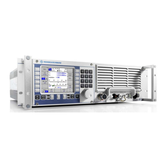
- Page 28 M3SR Series 4100 List of Figures Figure 1.1 R&S M3SR Series 4100 Radio (Front View) ................1.2 Figure 1.2 R&S M3SR Series 4100 Radio, e.g. Transceiver (Top View without Cover, Example)..... 1.6 Figure 1.3 R&S IN4190 Power Supply ..................... 1.11 Figure 1.4 R&S IN4000A Power Supply ....................
- Page 29 M3SR Series 4100 List of Figures Figure 3.7 Example of a Softkey....................... 3.16 Figure 3.8 Example of a Listbox ....................... 3.17 Figure 3.9 Example of an Editor ....................... 3.18 Figure 3.10 Menu Number and Title ......................3.20 Figure 3.11 Menu Numbering ........................3.21 Figure 3.12 Menu Tree in Fixed Frequency Operation ................
- Page 30 M3SR Series 4100 List of Figures Figure 3.48 Menu 3004: Radio MTC 4/7: Response Option Key ............... 3.87 Figure 3.49 Option Key Editor ........................3.89 Figure 3.50 Option Key Details Message Box (Example)................3.90 Figure 3.51 Menu 3005: Radio MTC 5/7 ....................3.91 Figure 3.52 Menu 3006: Radio MTC 6/7 ....................
- Page 31 M3SR Series 4100 List of Figures Figure 4.1 Valid Option Keys in Menu Radio MTC 4/7 (Example).............. 4.2 Figure 4.2 Menu Tree: ALE-2G ........................ 4.11 Figure 4.3 Home Menu: ALE-2G (Listening, Rx Mode) ................4.12 Figure 4.4 Home Menu: ALE-2G (Listening, Tx Mode)................4.13 Figure 4.5 Menu 1211: ALE OP 1/2 (ALE-2G) ..................
- Page 32 M3SR Series 4100 List of Figures Figure 4.42 Hopset Folder Main Menu in CFG 2/2 Menu ................. 4.194 Figure 4.43 Keyset Folder Main Menu in CFG 2/2 Menu ................. 4.195 Figure 4.44 Keyset Folder Main Menu in CFG 2/2 Menu ................. 4.205 Figure 5.1 GPS Reporting System ......................
- Page 33 M3SR Series 4100 List of Figures Figure 6.1 Replacing the Fuses F1 / F2 ..................... 6.2 Figure 6.2 GO LED on Radio Front Panel and GO LED on Control Panel Switched Off in Case of Error (Example) ..........................6.4 Figure 6.3 Menu Radio MTC 1/7 Indicating an Error (Example)..............
- Page 34 M3SR Series 4100 List of Tables Table 1.1 Applicable Software and Software Options (Option Keys) ............1.1 Table 1.2 Available Power Supply Models ....................1.12 Table 1.3 Signal Modulations ........................1.14 Table 2.1 Default IP Settings of a Radio ....................2.32 Table 2.2 Default IP Settings of Control Unit ...................
- Page 35 M3SR Series 4100 List of Tables Table 3.32 Softkeys in Menu CU MTC 2/4 ....................3.112 Table 3.33 Softkeys in Menu CU MTC 3/4 ....................3.118 Table 3.34 Softkeys in Menu CU MTC 4/4 (4004)................... 3.120 Table 3.35 Menu Structure as Function of Modulation Mode ..............3.130 Table 3.36 Possible States of FF Scanning ....................
- Page 36 M3SR Series 4100 Index Numerics ALE-3G ALM Enable ............4.112 ALE-3G Configuration Menus ...........4.84 1 kW Mode ................3.64 ALE-3G Home Menus ............4.74 2 kW Mode ................3.64 ALE-3G Linking Protection ..........4.111 4 kW Mode ................3.64 ALE-3G Menu Tree ............4.71 ALE-3G Operational Menus ..........4.76 Alert Inbox ................5.99 Alert Messages ..............5.98 A1A Holdtime ..............3.174...
- Page 37 M3SR Series 4100 Index Basics of Message Service ..........5.89 Changing the MGC Level ..........3.145 Basics of SECOM-H ............4.157 Changing the Modem DeAcquire Limit ......4.134 Basics of Secure Digital Voice ........4.145 Changing the Modem Doppler Tracking Time ....4.135 Basics of Voice over IP (VoIP) ........5.101 Changing the Modem TX Level Control Blocks ....4.138 Baud Rate ...............3.165 Changing the Modulation Mode ......
- Page 38 M3SR Series 4100 Index Continuous Built-In Test (CBIT) ..........6.8 Dust Protection Filter ............7.3 Control and Monitoring of Radio and Control Unit ....3.29 Dwell Time ..............3.216 Control Unit ............... 1.8 3.10 Control Unit Built-In Test ...........6.10 Control Unit Error Details (4012) ........3.105 Editing a User Hopset .............4.194 Control Unit Error List (4011) ..........3.103 Editing a User Hopset Subband ........4.200...
- Page 39 M3SR Series 4100 Index Free Hopset Search ..........4.160 4.169 HF Modem Waveform .............4.140 Free Hopset Search Mode ..........4.184 HiSp Async ..............4.142 Frequency ...............3.151 Hold Time ............... 3.217 Frequency Editor .............3.151 Home Menu Frequency Scanning Parameter ........3.209 ALE 2G (Listening, Rx Mode) ........4.12 Frequency Shift for F1D ..........3.167 ALE-2G (Listening, Tx Mode) ........4.13 Frequency Step Size Editor ........
- Page 40 M3SR Series 4100 Index IP_DATA .................4.167 IP_REBRO ..............4.167 Maintaining Network Synchronism ........4.8 IP-Based Interface for External Applications ....5.90 Maintenance Menus ............3.47 IPoA (IP Over Air) .............5.32 Manu 3022 IPoA Configuration Menus ..........5.69 Radio Inventory Details (Example) ........3.62 IPoA Multicast Routing Menu ..........5.87 Manual Push ...............5.7 IPoA protocol ARQ ............5.40 MELP ................4.191...
- Page 41 M3SR Series 4100 Index Menu 1621 Menu Page Design ............3.11 Sec. Voice Cfg 1/1 ............4.154 Menu Radio Error Details (3012) ........3.57 Menu 3001 Menu Radio Error List (3011) ...........3.55 Radio MTC 1/7 ...............3.50 Menu Radio Error List (Example) ........6.6 Menu 3002 Menu Radio Inventory (3021) ...........3.59 Radio MTC 2/7 ...............3.74 Menu Radio Inventory Indicating a Defective Module...
- Page 42 M3SR Series 4100 Index Navigation within the Menu Tree ........3.27 Power-On Built-In Test (PBIT) ..........6.5 Net (Network Connection Mode) ........5.80 PPP IP Interface Address ..........5.73 Net Call ................4.18 Preamplifier ..............3.142 Net Calls ................4.4 Preset Page ..............3.44 Network Connection Mode ..........5.80 Priority Based Session Management ........4.95 Network Infrastructure, e.g.
- Page 43 M3SR Series 4100 Index Rebroadcast Scenario, e.g. M3TR Radios .......5.55 Selecting a Keyset ............4.179 Rebroadcsat IP Address ...........5.75 Selecting One of the Received GPS Position Recalling Settings ............3.136 Information ................5.30 Received GPS Position Information ........5.30 Selecting Remote Radio ...........3.30 Receiver Filter Bandwidth ..........3.147 Selecting the Active Channel for 'Fix' Operation ....4.25 Recommendations for the Transport Layer ......5.36 Selecting the Active COMSEC Key for...
- Page 44 M3SR Series 4100 Index SIP Proxy and SIP Registrar ...........5.119 Softkey 'Data Params' ............3.83 SIP Registrar ..............5.119 Softkey 'Datarate' ............4.187 SIP Signalling ..............5.122 Softkey 'Date Time' ........3.77 4.50 4.192 Softkey ..............4.19 4.78 Softkey 'DCD Mode' ............3.84 Softkey '<-' ................3.19 Softkey 'Deacquire' ............4.134 Softkey '->' ................3.19 Softkey 'Default LM Voice' ..........4.43...
- Page 45 M3SR Series 4100 Index Softkey 'Insert Transmitter' ..........3.72 Softkey 'Passive Time ACQ' ......... 4.51 4.104 Softkey 'Insert' ..............4.197 Softkey 'PBT' ..............3.157 Softkey 'Installed Modules' ..........3.61 Softkey 'Play LDV Message' ..........4.83 Softkey 'INTLV' ...............4.189 Softkey 'PMU Mode' ............3.67 Softkey 'Intvl Data' ............4.119 Softkey 'PMU' ..............3.53 Softkey 'Intvl Voice' ............4.116 Softkey 'POL RX' ............3.166...
- Page 46 M3SR Series 4100 Index Softkey 'SQL Mode' ............3.179 Softkeys in Menu Radio Error Details (3012) ....3.58 Softkey 'SQL Tone' ..........3.138 3.206 Softkeys in Menu Radio Error List (3011) ......3.56 Softkey 'Squelch' ..........3.140 3.208 Softkeys in Menu Radio Inventory (3021) ......3.61 Softkey 'Start (kHz)' ............3.209 Softkeys in Menu Radio MTC 1/7 (3001) ......3.51 Softkey 'Start IBIT' ..........3.54...
- Page 47 M3SR Series 4100 Index Switching the LQA Request On or Off ......4.39 Unicast Routing Table ............5.82 Switching the Multitone Function On or Off ....3.163 Universal Transverse Mercator (UTM) Positioning Switching the Occupancy Detection On or Off ....4.106 Information ................5.18 Switching the Popup for Received AMD Messages Unpacking and Checking ............2.1 On or Off ................4.38 Unprotected Time Request (Random Value) ....4.52...
- Page 48 M3SR Series 4100 Index ZF4401, mod. 02 ...............2.10 Operating Manual 6175.4760.02 – 01...
-
Page 49: User Information
M3SR Series 4100 User Information 1 User Information This description deals with the following equipment: • R&S EK4100A / R&S EK4100D Receiver • R&S GX4100A / R&S GX4100D Receiver / Exciter • R&S XK4115A / R&S XK4115D Transceiver • R&S GV4190A / R&S GV4190D Power Management Unit (PMU) Applicable software and options are shown in Table 1.1. -
Page 50: General Features
M3SR Series 4100 User Information With the activated option R&S GS4117S the HF transceivers of the R&S M3SR Series 4100 family were tested in accordance with ETSI EN 300 373-1 V1.2.1 (2002-10) with the following deviation: • ETSI EN 300 373-1 / 7.6 Corrosion Test The device must be operated in a room where it is protected against the effects of cor- rosive environment. - Page 51 M3SR Series 4100 User Information Beside the traditional classes of emission used in HF radiocommunications (A1A, J3E and J2D in the upper and lower sidebands, A3E, F3E, F1B, B8E, B7D, R3E and H3E), the fol- lowing important standards from the "HF house" are integrated and available as software options: HF modems STANAG-4285, 4481, 4529 and 5065, 4415, 4539, Annex B, MIL-STD-188-110B and the ISB modem MIL-STD-188-110B Appendix F automatic link es-...
-
Page 52: Explanation Of Models
M3SR Series 4100 User Information • Secure communication EPM (ECCM) method R&S SECOM-H for secure and jam-resistant voice and data links Powerful crypto algorithm Management of "black" keys offers additional security Data link capability in line with STANAG-5511 and STANAG-5522 (SW option) Centralized network, crypto, and frequency management capabilities for configuring Rohde &... -
Page 53: Design
M3SR Series 4100 User Information 1.4 Design All radios consist of the following modules: • Front Panel • Motherboard • R&S IN4400A AC/DC Power Supply (Receiver) • Power Supply (Receiver / Exciter) • Power Amplifier (Transceiver) • PMU Unit (Power Management Unit) •... -
Page 54: Figure 1.2 R&S M3Sr Series 4100 Radio, E.g. Transceiver (Top View Without Cover, Example)
M3SR Series 4100 User Information Figure 1.2 R&S M3SR Series 4100 Radio, e.g. Transceiver (Top View without Cover, Example) ICN-4D-F-231000-R-D0894-00005-A-01-1 Operating Manual 6175.4760.02 – 01... - Page 55 M3SR Series 4100 User Information 1 Interface Module 2 Power Amplifier 3 Front Panel 4 R&S GB4000C (option) 5 R&S FK4120 (option) 6 Synthesizer 7 Frontend 8 Radio Controller Operating Manual 6175.4760.02 – 01...
-
Page 56: Functioning Of E.g. Receiver / Exciter
M3SR Series 4100 User Information 1.5 Functioning of e.g. Receiver / Exciter The modules are controlled and monitored by the control logic, part of the module Mother- board. In addition, the control logic contains a memory for configuration data and module parameters. -
Page 57: General Data
M3SR Series 4100 User Information 1.6 General Data For more information refer to sect. 9 Drawings Operating Manual 6175.4760.02 – 01... -
Page 58: Required Power Supply
M3SR Series 4100 Required Power Supply 1.7 Required Power Supply 1.7.1 Required Power Supply for Receiver No power supply is required. The internal Power Supply R&S IN4400A needs an input voltage of 100 V AC to 240 V AC / 50 Hz to 60 Hz. The radio may also be powered by an external battery (19V DC to 31 V DC). -
Page 59: Required Power Supply For Receiver / Exciter Or Pmu
M3SR Series 4100 Required Power Supply for Receiver / Exciter or PMU 1.7.2 Required Power Supply for Receiver / Exciter or PMU The 500 W / 1000 W transceiver system needs several supply voltages, provided by the ex- ternal R&S IN4150 or R&S IN4190 Power Supply ((see Figure 1.3), same appearance). The power supply is available in several models which are designed for different input voltages (see table overleaf). -
Page 60: Table 1.2 Available Power Supply Models
M3SR Series 4100 Required Power Supply for Receiver / Exciter or PMU Table 1.2 Available Power Supply Models Type designation Order no. Model Supply Frequency (Hz) R&S IN4150 6120.0705.02 1/3PH (+n) 230 V AC (1PH)+10/-15% 47 to 63 208 V AC ()+10/-15% 47 to 63 230 V AC (Y)+10/-15% 47 to 63... -
Page 61: Required Power Supply For Transceiver
M3SR Series 4100 Required Power Supply for Transceiver 1.7.3 Required Power Supply for Transceiver The radio operates on a DC voltage of 28 V DC (28 V DC to 29 V DC). This voltage is pro- vided as an option by the external R&S IN4000A Power Supply (19" rackmount of 1 height unit, see Figure 1.4) available for the purpose. -
Page 62: Communication Capabilities
M3SR Series 4100 Communication Capabilities 1.8 Communication Capabilities 1.8.1 Voice Communication Voice transmission is possible in both digital and analog mode. Depending on the software configuration, the radio is able to transmit and receive the signal modulations in the RF band (emission designators according to CCIR) as listed in Table 1.3. -
Page 63: Data Communication
M3SR Series 4100 Communication Capabilities Squelch Modes The following squelch functions are incorporated: • Carrier squelch RSSI (Receive Signal Strength Indication) • Signal squelch (tone frequency selectable from a list) • Syllabic squelch (voice-operated squelch) • Squelch off Embedded Digital Voice Services (only in optional R&S SECOM-H mode) For digital voice transmission the following vocoders are implemented as software modules: •... -
Page 64: Radio Control
M3SR Series 4100 Radio Control 1.9 Radio Control The control unit and the radio front panel are the main user interface to control and monitor the radio operation (for details see sect. 3 Operation). The radio as stand-alone tabletop unit with built-in control unit is shown in Figure 1.5. -
Page 65: Figure 1.6 Radio With Additional Remote Control Unit
M3SR Series 4100 Radio Control Figure 1.6 Radio with Additional Remote Control Unit ICN-4D-C-231000-R-D0894-00011-A-01-1 1 Remote Control Unit 2 Network (LAN) the Radio and Control Unit are connected to 3 Radio with Built-In Control Unit Operating Manual 6175.4760.02 – 01 1.17... -
Page 66: Radio With Several Control Units
M3SR Series 4100 Radio Control To guarantee the proper operation of both radio and control unit connected to a local area network (LAN), the IP settings of the radio as well as the IP settings of the control unit need to be configured accordingly before connecting radio and control unit to the LAN (see sect. -
Page 67: Figure 1.7 Radio With Built-In Control Unit And With Two Remote Control Units
M3SR Series 4100 Radio Control Figure 1.7 Radio with Built-In Control Unit and with two Remote Control Units ICN-4D-C-231000-R-D0894-00012-A-01-1 1 Remote Control Unit 2 Network (LAN) the Radio and Control Units are connected to 3 Radio with Built-In Control Unit Operating Manual 6175.4760.02 –... -
Page 68: Several Radios And Control Units In A Network
M3SR Series 4100 Radio Control A radio can service several control units, but only one control unit can have opera- tional access rights at a time, the other control units can have only monitoring rights (for details about radio access rights see sect. 3.3 Control and Monitoring of Radio and Control Unit). -
Page 69: Figure 1.5 Radio With Built-In Control Unit
M3SR Series 4100 Radio Control Figure 1.8 Several Radios and Remote Control Units in a Network (Example) ICN-4D-C-231000-R-D0894-00013-A-01-1 1 Radio with Built-In Control Unit 2 Radio without Built-In Control Unit 3 Remote Control Unit 4 Hub (Network Component) 5 Router (Network Component) 6 e.g. - Page 70 M3SR Series 4100 Radio Control 1.22 Operating Manual 6175.4760.02 – 01...
-
Page 71: Getting Started
M3SR Series 4100 Getting Started 2 Getting Started 2.1 Unpacking, Checking, Packing, Transport and Storage 2.1.1 Unpacking and Checking After delivery carry out the following steps: 1. Check the packaging for damage. 2. Unpack the delivered goods. 3. Check the delivered goods (including accessories) against the delivery note. 4. -
Page 72: Transport
M3SR Series 4100 Unpacking, Checking, Packing, Transport and Storage 2.1.3 Transport For data such as permissible altitude for air transport see the data sheet. During transport provide sufficient mechanical and antistatic protection of the unit (see ”Packing” on p. 2.1)! 2.1.4 Storage For data such as permissible storage temperature see the data sheet. -
Page 73: Installation And Removal
M3SR Series 4100 Installation and Removal 2.2 Installation and Removal Refer to (sect. 9 Drawings: Interface Description). Installation For installation (see Figure 2.1) into a 19" rack with telescopic slides proceed as follows: 1. Take the right-hand telescopic slide and extend it as far as possible. 2. -
Page 74: Figure 2.1 Installation Into A 19" Rack, Example
M3SR Series 4100 Installation and Removal Figure 2.1 Installation into a 19" Rack, Example 26.4 12.4 11.2 ICN-4D-G-231000-R-D0894-00148-A-01-1 Operating Manual 6175.4760.02 – 01... -
Page 75: Removal
M3SR Series 4100 Installation and Removal 1 Fixing at rack at the front-side 2 The maximum screw-in depth is 3.5 mm 3 8 x Phillips screws M4 x 6 (Ident. no.: 0396.8181.00) 8 x washers (Ident. no.: 0005.0315.00) 4 Telescopic slide (Ident. no.: 0657.5807.00 (6105.9263.00)) 5 Extension of the telescopic slide: 377.7 mm (530.1 mm) 6 Side length: 457.2 mm (508 mm) The telescopic slides are available on demand (Ident. -
Page 76: Rear Cabling
M3SR Series 4100 Rear Cabling 2.3 Rear Cabling 2.3.1 Rear Cabling for Receiver Connect the mains cable only after all other wiring has been made. The unit has an all-pole protection (neutral line protection). If an external power supply is used to provide the device with extra-low DC voltage (SELV), the requirements for reinforced or double insulation according to DIN/EN/IEC 61010 (UL 3111, CSA C22.2 No. -
Page 77: Figure 2.2 Rear Connectors Of Receiver
M3SR Series 4100 Rear Cabling Necessary cabling at the rear side: Figure 2.2 Rear Connectors of Receiver ICN-4D-C-231000-R-D0894-02006-A-01-1 1 Mains Connector X1 2 Ground Connector 3 Rx Antenna Connector X2111 4 not used in this application 5 GPS Antenna Connector X2113 6 LAN Connector X20 7 REMOTE Connector X24 8 RCB SER Connector X21(control) -
Page 78: Rear Cabling For Receiver / Exciter
M3SR Series 4100 Rear Cabling for Receiver / Exciter 2.3.2 Rear Cabling for Receiver / Exciter Connect the mains cable only after all other wiring has been made. When using an RF broadband system provide appropriate lightning protection and grounding. If an external power supply is used to provide the device with extra-low DC voltage (SELV), the requirements for reinforced or double insulation according to DIN/EN/IEC 61010 (UL 3111, CSA C22.2 No. -
Page 79: Figure 2.3 Rear Connectors Of Receiver / Exciter
M3SR Series 4100 Rear Cabling for Receiver / Exciter Necessary cabling at the rear side: Figure 2.3 Rear Connectors of Receiver / Exciter ICN-4D-C-231000-R-D0894-00006-A-01-1 1 Ground Connector 2 Rx Antenna Connector X2111 3 Rx/Tx Connector X2112 to external power amplifier (e.g. R&S VK4150 or R&S VK4190) 4 GPS Antenna Connector X2113 5 LAN Connector X20 6 REMOTE Connector X24... -
Page 80: Rear Cabling For Transceiver
M3SR Series 4100 Rear Cabling for Transceiver 2.3.3 Rear Cabling for Transceiver Connect the mains cable only after all other wiring has been made. If an external power supply is used to provide the device with extra-low DC voltage (SELV), the requirements for reinforced or double insulation according to DIN/EN/IEC 61010 (UL 3111, CSA C22.2 No. -
Page 81: Figure 2.4 Rear Connectors Of Transceiver
M3SR Series 4100 Rear Cabling for Transceiver Necessary cabling at the rear side: Figure 2.4 Rear Connectors of Transceiver ICN-4D-C-231000-R-D0894-00007-A-01-1 1 Antenna Connector X30 2 Ground Connector 3 Rx Antenna Connector X2111 4 GPS Antenna Connector X2113 5 LAN Connector X20 6 REMOTE Connector X24 7 RCB SER Connector X21(control) 8 DATA/RS232 Connector X23... -
Page 82: Rear Cabling For Power Management Unit
M3SR Series 4100 Rear Cabling for Power Management Unit 2.3.4 Rear Cabling for Power Management Unit Connect the mains cable only after all other wiring has been made. When using an RF broadband system provide appropriate lightning protection and grounding. The R&S M3SR Series 4100 radio includes a single mode transceiver, which is a class 1 laser product. -
Page 83: Figure 2.5 Rear Connectors Of Power Management Unit
M3SR Series 4100 Rear Cabling for Power Management Unit Necessary cabling at the rear side: Figure 2.5 Rear Connectors of Power Management Unit ICN-4D-C-231000-R-D0894-00008-A-01-1 Operating Manual 6175.4760.02 – 01 2.13... - Page 84 M3SR Series 4100 Rear Cabling for Power Management Unit 1 Multi-purpose Input/Output Connector X457 (MP I O) 2 HF Connector X602 (GX2) to X604 (GX4) to external receiver / exciter 3 Ground Connector 4 HF Connector X635 (TO PMU) to external PMU 5 HF Connector X611 (VK1) to X614 (VK4) to R&S VK4190 1 kW Power Amplifier 6 DELAY B Connector X638 7 Rx Antenna Connector X2111...
-
Page 85: Front Cabling
M3SR Series 4100 Front Cabling 2.4 Front Cabling Necessary cabling at the front side: Figure 2.6 Front Cabling ICN-4D-C-231000-R-D0894-00009-A-01-1 1 Headset Connector for e.g. R&S GA3002 2 Fillgun Connector for e.g. R&S GP3000 Operating Manual 6175.4760.02 – 01 2.15... -
Page 86: System Cabling
M3SR Series 4100 System Cabling 2.5 System Cabling 2.5.1 System Cabling for Receiver / Exciter Connect the mains cable only after all other wiring has been made. If an external power supply is used to provide the device with extra-low DC voltage (SELV), the requirements for reinforced or double insulation according to DIN/EN/IEC 61010 (UL 3111, CSA C22.2 No. -
Page 87: Figure 2.7 Cabling Between R&S Gx4100A/D, R&S Vk4190 And R&S In4190
M3SR Series 4100 System Cabling Figure 2.7 Cabling between R&S GX4100A/D, R&S VK4190 and R&S IN4190 ICN-4D-C-231000-R-D0894-00014-A-02-1 Operating Manual 6175.4760.02 – 01 2.17... - Page 88 M3SR Series 4100 System Cabling 1 Control Cable / Fiber Optic (receiver / exciter X21 – power amplifier X31), R&S GK4101, 6120.5607.xx (xx: 10 = 1.0 m, 35 = 3.5 m, 50 = 50 m) 2 DC Cable (receiver / exciter X31 – power amplifier X24), R&S GK4104, 6120.5907.xx (05 = 0.5 m, 10 = 1.0 m, 25 = 2.5 m) 3 RF Cable (receiver / exciter X2112 –...
-
Page 89: System Cabling For Transceiver
M3SR Series 4100 System Cabling for Transceiver 2.5.2 System Cabling for Transceiver Connect the mains cable only after all other wiring has been made. If an external power supply is used to provide the device with extra-low DC voltage (SELV), the requirements for reinforced or double insulation according to DIN/EN/IEC 61010 (UL 3111, CSA C22.2 No. -
Page 90: Figure 2.8 System Cabling For Transceiver
M3SR Series 4100 System Cabling for Transceiver Figure 2.8 System Cabling for Transceiver ICN-4D-F-231000-R-D0894-00136-A-01-1 1 Mains Connection 2 Ground Connection 3 Ground Connection (M6) 4 DC cable (R&S IN4000A Power Supply – R&S XK4115), for instance R&S GK4103, 6120.5807.xx ( xx: 05 = 0.5 m, 10 = 1.0 m, 25 = 2.5 m) 5 Antenna Tuning Unit Connection (Control) 6 Battery Connection 7 Antenna or Antenna Tuning Unit Connection (RF), Type N... -
Page 91: System Cabling For Hf Broadband System
M3SR Series 4100 System Cabling for HF Broadband System 2.5.3 System Cabling for HF Broadband System Connect the mains cable only after all other wiring has been made. If an external power supply is used to provide the device with extra-low DC voltage (SELV), the requirements for reinforced or double insulation according t DIN/EN/IEC 61010 (UL 3111, CSA C22.2 No. - Page 92 M3SR Series 4100 System Cabling for HF Broadband System For detailed information on connectors and contact assignment see the interface de- scription (sect. 9 Drawings). For basic information, see sect. 2.5 System Cabling. The connections • receiver / exciter X31 – power amplifier X24, •...
-
Page 93: Switching The Radio On
M3SR Series 4100 Switching the Radio On 2.6 Switching the Radio On Minimum Requirements Before putting the radio into operation make sure that the following minimum requirements are met: • Power supply is switched on (see the power supply documentation). •... -
Page 94: Figure 2.10 Switching The Radio With Built-In Control Unit On
M3SR Series 4100 Switching the Radio On Figure 2.10 Switching the Radio with Built-In Control Unit On ICN-4D-C-231000-R-D0894-00016-A-01-1 1 Radio Button ON / OFF 2 Radio LED AC / DC 3 Radio LED BATT (Battery) 4 Radio LED GO 5 Control Unit Button ON / OFF 6 Control Unit LED ON 7 Control Unit LED CU 8 Control Unit LED GO... -
Page 95: Switching On
M3SR Series 4100 Switching the Radio On Switching On For HF-Broadband system (HF-BB) All system components has to be switched on at the same time (R&S GV4190 and all R&S GX4100 and R&S VK4190). By pressing 'ON/OFF' (1 and Figure 2.10) at the radio front panel the radio is switched on. If a built-in control unit is installed, it will be switched on automatically, too. - Page 96 M3SR Series 4100 Switching the Radio On For R&S IN4150 / R&S IN4190 The BATT LED is switched off if the main power supply fails; however, the radio and ampli- fers are still connected to the battery. 2.26 Operating Manual 6175.4760.02 – 01...
-
Page 97: Automatic Update Of Modules
M3SR Series 4100 Automatic Update of Modules 2.6.1 Automatic Update of Modules The radios test the firmware versions of connected internal and external hardware modules after switching on. If any old or wrong versions are detected, an automatic update is offered to ensure optimal performance of the radio system. -
Page 98: Figure 2.11 Example For The Automatic Update Process Of A Frontend
M3SR Series 4100 Automatic Update of Modules Figure 2.11 Example for the Automatic Update Process of a Frontend ICN-4D-G-231000-R-D0894-00099-A-01-1 1 Wrong Module Version Found 2 Continue Boot Process 2.28 Operating Manual 6175.4760.02 – 01... - Page 99 M3SR Series 4100 Automatic Update of Modules When the update process is finished, switch off all components for at least 15 seconds in order to activate the new firmware. The update process (erasing and programming of new firmware) can take several min- utes to finish.
-
Page 100: Switching The Radio Off
M3SR Series 4100 Switching the Radio Off 2.7 Switching the Radio Off Figure 2.12 Switching the Radio Off ICN-4D-C-231000-R-D0894-00015-A-01-1 1 Radio Button ON / OFF 2 Radio LED AC / DC 3 Radio LED BATT (Battery) 4 Radio LED GO 2.30 Operating Manual 6175.4760.02 –... -
Page 101: Figure 2.13 Switching The Radio With Built-In Control Unit Off
M3SR Series 4100 Switching the Radio Off Figure 2.13 Switching the Radio with Built-In Control Unit Off ICN-4D-C-231000-R-D0894-00017-A-01-1 1 Radio Button ON / OFF 2 Radio LED AC / DC 3 Radio LED BATT (Battery) 4 Radio LED GO 5 Control Unit Button ON / OFF 6 Control Unit LED ON 7 Control Unit LED CU 8 Control Unit LED GO... -
Page 102: Basic Configuration Of The Radio
M3SR Series 4100 Basic Configuration of the Radio 2.8 Basic Configuration of the Radio The radio can be controlled and monitored via local area network (LAN) with one or more external control units also connected to the LAN (see sect. 1.9 Radio Control). To guarantee proper operation in this case it is required to change the default Internet protocol (IP) settings of the radio (for default IP settings of the radio see Table 2.1) as well as the default IP settings of the control unit (for default IP settings of the control unit see sect. -
Page 103: Changing Radio Ip Settings Using A Built-In Control Unit
M3SR Series 4100 Basic Configuration of the Radio 2.8.1 Changing Radio IP Settings Using a Built-in Control Unit The following description guides through the individual steps required to change the radio default IP settings (see Table 2.1) with the help of the built-in control unit. These instructions assume that to begin with the default IP settings are selected on both radio and built-in con- trol unit (see Table 2.1 and sect. - Page 104 M3SR Series 4100 Basic Configuration of the Radio Press softkey. Press softkey. Press softkey. 5. IP settings are complete. Press button. 6. Disconnect the CU from the radio. Press softkey. 7. Switch the radio off to make the changes take effect. After changing the radio IP settings (especially radio IP address) it is also required to change the built-in control unit IP settings (especially radio IP address list, see sect.
-
Page 105: Changing Radio Ip Settings Using Upd32.Exe Tool
M3SR Series 4100 Basic Configuration of the Radio Figure 2.14 Radio IP Settings (Example) ICN-4D-J-231000-R-D0894-00085-A-01-1 1 Radio IP Address 2 Radio Subnet Mask 3 Radio Gateway Address 2.8.2 Changing Radio IP Settings Using Upd32.exe Tool The following description guides through the individual steps required to change the radio default IP settings (see Table 2.1) with the help of the upd32.exe tool. -
Page 106: Figure 2.15 Changing Radio Ip Settings Using The Upd32.Exe Tool
M3SR Series 4100 Basic Configuration of the Radio Figure 2.15 Changing Radio IP Settings Using the upd32.exe Tool ICN-4D-C-231000-R-D0894-00086-A-01-1 1 PC 2 LAN 3 Radio 2.36 Operating Manual 6175.4760.02 – 01... - Page 107 M3SR Series 4100 Basic Configuration of the Radio To change the IP settings of the radio using the upd32.exe proceed as follows: 1. Connect radio backplane LAN connector and PC to LAN (see Figure 2.15). 2. Press the Erase button at the radio front panel (make sure that radio is switched off be- forehand).
-
Page 108: Figure 2.16 Upd32: Select 'Lan Settings Via Ethernet
M3SR Series 4100 Basic Configuration of the Radio Figure 2.16 Upd32: Select 'LAN Settings via Ethernet' ICN-4D-F-231000-R-D0894-00087-A-01-1 Figure 2.17 Upd32: Select Targets for Ethernet Communication Dialog (Example) ICN-4D-F-231000-R-D0894-00088-A-01-1 2.38 Operating Manual 6175.4760.02 – 01... -
Page 109: Figure 2.18 Upd32: Lan Setting Dialog (Example)
M3SR Series 4100 Basic Configuration of the Radio Figure 2.18 Upd32: LAN Setting Dialog (Example) ICN-4D-F-231000-R-D0894-00089-A-01-1 Figure 2.19 Upd32: Finish the Update ICN-4D-F-231000-R-D0894-00090-A-01-1 Operating Manual 6175.4760.02 – 01 2.39... -
Page 110: Basic Configuration Of The Control Unit
M3SR Series 4100 Basic Configuration of the Control Unit 2.9 Basic Configuration of the Control Unit The control unit IP configuration consists of two parts. • The control unit IP Settings: IP address, netmask and gateway. The IP address uniquely identifies the control unit within the LAN (see Figure 2.20). - Page 111 M3SR Series 4100 Basic Configuration of the Control Unit Press softkeys to change the IP settings (IP Address, Subnet Mask and Gateway) of the control unit. For details see also sect. 3.5.2 Control Unit MTC 2/4 (4002). Press softkey and the display appears as shown in Figure 2.21. Press softkeys to Insert, Delete or Edit an entry in the list.
-
Page 112: Figure 2.20 Control Unit Ip Settings
M3SR Series 4100 Basic Configuration of the Control Unit Figure 2.20 Control Unit IP Settings ICN-4D-G-231000-R-D0894-00093-A-01-1 1 Control Unit IP Address 2 Control Unit Subnet Mask 3 Control Unit Gateway Address 2.42 Operating Manual 6175.4760.02 – 01... -
Page 113: Figure 2.21 Radio Ip Address List Of Control Unit
M3SR Series 4100 Basic Configuration of the Control Unit Figure 2.21 Radio IP Address List of Control Unit ICN-4D-H-231000-R-D0894-00094-A-01-1 1 Logical Radio Address in Radio IP Address List 2 Radio IP Address in Radio IP Address List When the radio IP address is changed (via softkey on menu page 3002 or by a remote con- trol system), the MMI receives this new IP address and creates an entry in the radio address list in control unit maintenance menu 4003. -
Page 114: Example Configuration
M3SR Series 4100 Example Configuration 2.10 Example Configuration An example configuration is shown in Figure 2.22. Figure 2.22 Example Configuration ICN-4D-C-231000-R-D0894-00095-A-01-1 2.44 Operating Manual 6175.4760.02 – 01... - Page 115 M3SR Series 4100 Example Configuration 1 Control Unit Control Unit IP Address IP Addr: 192.168.52.23 Subnet Mask: 255.255.255.0 Gateway Addr: 0.0.0.0 Radio IP Address List Addr: 14 Local: IP-Addr: 192.168.52.14 2 LAN 3 Radio with Control Unit (Option) Control Unit IP Address IP Addr: 192.168.52.24 Subnet Mask: 255.255.255.0 Gateway Addr: 0.0.0.0...
- Page 116 M3SR Series 4100 Example Configuration 2.46 Operating Manual 6175.4760.02 – 01...
-
Page 117: Operation
M3SR Series 4100 Operation 3 Operation 3.1 Overview R&S M3SR Series 4100 is a new generation of software radios. Its parameters can be con- trolled both locally and remotely. For local control the radio can be delivered with a local (built-in) control unit. -
Page 118: Figure 3.2 Radio Backplane With Interfaces
M3SR Series 4100 Overview Figure 3.2 Radio Backplane with Interfaces ICN-4D-C-231000-R-D0894-00021-A-01-1 1 Audio/Line Connector 2 Serial Connector (RS-232-C, Data) 3 Serial Connector (RS-232-C, Remote Control) 4 LAN Connector If connected to a LAN, all functions of the radio can be remotely configured and controlled for example with the R&S GB4000C Control Unit. -
Page 119: Figure 3.3 Radio And Remote Control Unit Connected Via Lan
M3SR Series 4100 Overview Figure 3.3 Radio and Remote Control Unit Connected via LAN ICN-4D-C-231000-R-D0894-00011-A-01-1 1 Remote Control Unit 2 LAN 3 Radio Operating Manual 6175.4760.02 – 01... - Page 120 M3SR Series 4100 Overview The parameters of the radio are set and monitored via remote control interface. The remote control interface is available as packet interface (TCP/IP port) based on standard Ethernet. The R&S GB4000C uses this interface. However, any other client may use this interface for control or monitoring purposes as well.
-
Page 121: Operating Concept
M3SR Series 4100 Operating Concept 3.2 Operating Concept This documentation gives an overview of how to operate the radio via the front panel and a control unit. As for operation via control unit all operation is menu-based, details are provided relating to the menu page structure and the possibilities to navigate within the menu tree or to change settings. -
Page 122: Radio Front Panel
M3SR Series 4100 Operating Concept 3.2.1 Radio Front Panel The front panel contains several buttons, volume controls and the ERASE button, which are used to make a limited number of radio settings. LEDs are available to indicate the status of the radio. -
Page 123: Quick Erase
M3SR Series 4100 Operating Concept Radio Settings The following settings can be made at the front panel: • Adjusting the volume with the volume controls for the loudspeaker and headset • Switching the radio on or off with the ON/OFF button (see sect. 2.6 Switching the Radio On and sect. -
Page 124: Table 3.1 General
M3SR Series 4100 Operating Concept Tones Table 3.1 General Name Timing Diagram Audio Busy Alarm Mes- sage Re- ceived Error Notification / Confirmation Net Entry Re- quest Battery Low Operating Manual 6175.4760.02 – 01... - Page 125 M3SR Series 4100 Operating Concept Table 3.2 Phone Name Timing Diagram Audio Busy Ringback Call Waiting PTT active Connected Operating Manual 6175.4760.02 – 01...
-
Page 126: Control Unit
M3SR Series 4100 Operating Concept 3.2.2 Control Unit The control unit is the main user interface to control and monitor the radio. The control unit has various control elements (see Figure 3.5). Figure 3.5 Control Elements of R&S GB4000C Control Unit ICN-4D-C-231000-R-D0894-00022-A-01-1 1 Numeric keypad 2 Knob... -
Page 127: Leds
M3SR Series 4100 Operating Concept 3.2.2.1 LEDs The control unit has the following LEDs to indicate the status: • LED ON The LED is lighted if the control unit is switched on. The LED blinks if the control unit is switched off (= standby). •... -
Page 128: Menu Page Design
M3SR Series 4100 Operating Concept Figure 3.6 Menu Page Design (Example) ICN-4D-G-231000-R-D0894-00023-A-01-1 1 Menu Domain Symbol (see ”Icons and Symbols” on p. 3.13) 2 Indication : “Ciphered Communication“ or "PLAIN Communication" 3 Menu Number (see ”Menu Organization” on p. 3.20) 4 Menu Title (see ”Menu Organization”... -
Page 129: Icons And Symbols
M3SR Series 4100 Operating Concept 3.2.2.4 Icons and Symbols Icons and symbols are displayed in the menu header (see Figure 3.6). The icons indicate menu domains and communication modes. The following icons are available: Table 3.3 Icons Icon Note Indicates the main menu. Indicates the maintenance menu (see sect. -
Page 130: Table 3.4 Symbols
M3SR Series 4100 Operating Concept In addition, various symbols may be displayed in the menu header (see Figure 3.6). Table 3.4 Symbols Symbol Note Indicates that the radio squelch function currently mutes the audio. Indicates that the radio squelch function currently unmutes the audio. Switched to external loudspeaker. - Page 131 M3SR Series 4100 Operating Concept Symbol Note Splite Site mode active. The Transmitter is detached, reception with the loacal hardware. No GPS position available. 2D GPS position fix (up to three satellites). 3D GPS position fix (four or more satellites). Indicates DSC interface module (option): DSC not connected or not controlling the radio.
-
Page 132: Softkeys
M3SR Series 4100 Operating Concept 3.2.2.5 Softkeys Definition: A softkey is a key with variable, software-assigned function. The relevant function is indicat- ed by the softkey label shown beside the key. The softkey labels are software-assigned de- pending on the selected menu. In the remainder of the document a softkey label and its corresponding softkey are referred to as softkey in short. -
Page 133: Figure 3.8 Example Of A Listbox
M3SR Series 4100 Operating Concept Softkeys to Make Settings Softkeys are control elements used to make settings. The following four possibilities are available to make settings with softkeys: Toggle softkey: Table 3.5 Toggle Softkeys Softkey label Note Press this softkey to toggle between two settings. Both settings are listed in the toggle soft- key. -
Page 134: Figure 3.9 Example Of An Editor
M3SR Series 4100 Operating Concept The active setting is shown in blue in the softkey label, the selected setting is shown high- lighted in the listbox. If active and selected setting are not identical, press the ENT button to accept the selected value. Press the ESC CLR button to discard the selected setting and to close the listbox. -
Page 135: Table 3.8 Navigation Softkeys
M3SR Series 4100 Operating Concept There are several editors with special functions available in the GUI (e.g. frequency editor, IP address editor, ...). For details on how to operate these editors refer to the description of the corresponding menu pages. Activate softkey: If a trigger-like activate softkey (e.g. -
Page 136: Menu Organization
M3SR Series 4100 Operating Concept Locked Softkey All softkeys are protected via a user level. Three user levels are available (0 to 2). Softkeys which require higher user levels than the currently set system-wide level, are marked with a lock symbol at the left or right top corner. For further information see sect. 3.6 User Level. Table 3.9 Editor Softkeys Softkey label Note... -
Page 137: Figure 3.11 Menu Numbering
M3SR Series 4100 Operating Concept The menu numbers are organized as follows: Figure 3.11 Menu Numbering ICN-4D-C-231000-R-D0894-00028-A-01-1 1 First digit: domain 2 Second digit: waveform 3 Third digit: sub-domain 4 Fourth digit: submenu Operating Manual 6175.4760.02 – 01 3.21... -
Page 138: Table 3.10 Menu Organization, Numbering And Titles
M3SR Series 4100 Operating Concept • The first digit designates the domain the menu belongs to: 0 = Home menu 1 = Communication mode 2 = Fillgun 3 = Radio Maintenance (Radio MTC) 4 = CU Maintenance (CU MTC) • The second digit designates the communication mode the menu belongs to: 0 = Is not assigned to a communication mode (N.A.) 1 = Fixed Frequency (FF) -
Page 139: Table 3.2 Phone
M3SR Series 4100 Operating Concept Domain Communication Mode Subdomain Submenu or Sub-Subdo- main Name/Icon Name/Icon Name Menu Title dig. dig. dig. dig. Communication Operation FF OP 1/2 Mode FF OP 2/2 FF SCAN 1/2 Configuration FF CFG 1/2 FF CFG 2/2 FF SCAN 2/2 GPS OP (without GPS Reporting) - Page 140 M3SR Series 4100 Operating Concept Domain Communication Mode Subdomain Submenu or Sub-Subdo- main Name/Icon Name/Icon Name Menu Title dig. dig. dig. dig. Fillgun N.A. Root Fillgun Menu Radio MTC N.A. Root Radio MTC 1/7 Radio MTC 2/7 Radio MTC 3/7 Radio MTC 4/7 Radio MTC 5/7 Radio MTC 6/7...
-
Page 141: Menu Tree
M3SR Series 4100 Operating Concept Table 3.11 Domains and Parameters Domain Description Communication Operation This domain contains the parameters of the active communication Mode mode which are essential to operate the radio in this communication mode. Configuration This domain mainly contains the parameters to (pre)configure the ac- tive communication mode. -
Page 142: Figure 3.12 Menu Tree In Fixed Frequency Operation
M3SR Series 4100 Operating Concept Figure 3.12 Menu Tree in Fixed Frequency Operation ICN-4D-J-231000-R-D0894-00029-A-01-1 3.26 Operating Manual 6175.4760.02 – 01... -
Page 143: Navigation Within The Menu Tree
M3SR Series 4100 Operating Concept See sect. 9 Drawings for a complete menu tree. 3.2.2.8 Navigation within the Menu Tree To navigate in the menu tree use the navigation softkeys. Table 3.12 Navigation Softkeys Softkey label Note Softkeys labelled with three dots '...' or with an arrow are softkeys for navigation. Press this softkey to navigate one menu back (e.g. -
Page 144: Figure 3.13 Position Of Softkey 'Previous' (Example)
M3SR Series 4100 Operating Concept Figure 3.13 Position of Softkey 'Previous' (Example) ICN-4D-G-231000-R-D0894-00030-A-01-1 1 Softkey 'PREV' Depending on the state of connection (see sect. 3.3 Control and Monitoring of Radio and Control Unit), the session type (see sect. 3.3 Control and Monitoring of Radio and Control Unit) or special radio states or modes, some menus will be disabled. -
Page 145: Control And Monitoring Of Radio And Control Unit
M3SR Series 4100 Control and Monitoring of Radio and Control Unit 3.3 Control and Monitoring of Radio and Control Unit This chapter gives all the details necessary to operate and configure the radio with the help of the control unit. It introduces the Home menu in detail. 3.3.1 Home Menu (0001) After switching on the radio, the built-in control unit comes up with the Home menu. -
Page 146: Connecting To Radio
M3SR Series 4100 Control and Monitoring of Radio and Control Unit 3.3.1.1 Connecting to Radio If the control unit was not connected to a radio before power-off, the Home menu appears as shown in Figure 3.14. Figure 3.14 Home Menu, Not Connected ICN-4D-G-231000-R-D0894-00031-A-01-1 1 Softkey: Connect to Radio 2 Indication in Menu Header for Not Connected... -
Page 147: Figure 3.15 Selecting Remote Radio
M3SR Series 4100 Control and Monitoring of Radio and Control Unit Figure 3.15 Selecting Remote Radio ICN-4D-C-231000-R-D0894-00101-A-01-1 1 Remote 2 Local By pressing the 'Connect to Radio' softkey a list of logical addresses of radios which are configured in the control unit is opened. In case of a built-in control unit the 'LO- CAL' address might also be listed (see 1 and 2). -
Page 148: Figure 3.16 Home Menu, Connecting To Radio
M3SR Series 4100 Control and Monitoring of Radio and Control Unit Figure 3.16 Home Menu, Connecting to Radio ICN-4D-G-231000-R-D0894-00032-A-01-1 1 Softkey: Disconnect from Radio 2 Indication in Menu Header for connecting 3 Status Line: Connecting to radio, e.g. 34 If the radio to connect to is switched on and can be reached via LAN, the connecting status may be too short for the user to notice. -
Page 149: Figure 3.17 Example: Home Menu Connected, Active Communication Mode Is Fixed Frequency
M3SR Series 4100 Control and Monitoring of Radio and Control Unit Figure 3.17 Example: Home Menu connected, active communication mode is Fixed Frequency ICN-4D-G-231000-R-D0894-00033-A-01-1 1 Currently Active Session (see ”Session Types and Access Rights” on p. 3.35) 2 Logical Address of Radio Connected to 3 Navigation Softkeys to Communication Mode Domain Menus Now the radio-specific softkeys and also the navigation softkeys for radio-specific and com- munication mode domains are enabled. -
Page 150: Disconnecting From Radio
M3SR Series 4100 Control and Monitoring of Radio and Control Unit 3.3.1.2 Disconnecting from Radio Press the softkey 'Disconnect from Radio' if you no longer wish to control or monitor the radio you are connected to. If you want to control or monitor another radio, also press the softkey 'Disconnect from Radio'. -
Page 151: Session Types And Access Rights
M3SR Series 4100 Control and Monitoring of Radio and Control Unit 3.3.1.3 Session Types and Access Rights A radio can have up to 3 sessions at a time with control units connected to it. Only one control unit can have a session with operational access right, which gives it the right to manipulate settings of the radio.. -
Page 152: Figure 3.20 Example: Three Monitoring Sessions
M3SR Series 4100 Control and Monitoring of Radio and Control Unit To handle the available access rights, to each connection a session is assigned which occu- pies access rights. Each session occupies one monitoring access right and dependent on the type of the session also the operational access right. For details about the session types see Table 3.14. -
Page 153: Figure 3.21 Example: Radio Grants A Fixed Session
M3SR Series 4100 Control and Monitoring of Radio and Control Unit Figure 3.21 Example: Radio grants a Fixed Session Radio Operational Access Right Monitoring Session Control Unit Monitoring Access Right (1) Monitoring Session 1. Request Fixed Session Control Unit Monitoring Access Right (2) Monitoring Session Control Unit... -
Page 154: Figure 3.22 Example: Radio Denies An Advanced Session
M3SR Series 4100 Control and Monitoring of Radio and Control Unit Figure 3.22 Example: Radio denies an Advanced Session Radio Monitoring Session 1. Request Advanced Session Control Unit Monitoring Access Right (1) Fixed Session Control Unit Operational Access Right Monitoring Session Control Unit Monitoring Access Right (3) -
Page 155: Table 3.14 Session Types
M3SR Series 4100 Control and Monitoring of Radio and Control Unit The session types are explained in detail in the following table. Table 3.14 Session Types Session Type Meaning Occupied Access Rights Monitoring Operational Monitoring The user has no right to change radio param- eters, but he is able to monitor the settings. -
Page 156: Figure 3.23 Selecting A Session
M3SR Series 4100 Control and Monitoring of Radio and Control Unit Figure 3.23 Selecting a Session ICN-4D-G-231000-R-D0894-00039-A-01-1 You can select the session type before you connect to a radio. You can also change the ses- sion type with a connection already being established. The currently active session is displayed in the right upper corner of the menu header (MON, ADV, FIX or LOC, see Figure 3.24) and in the softkey label 'Session' in the Home menu. -
Page 157: Figure 3.24 Session Indication In Menu Header
M3SR Series 4100 Control and Monitoring of Radio and Control Unit Figure 3.24 Session Indication in Menu Header ICN-4D-G-231000-R-D0894-00040-A-01-1 The Advanced (ADV) or Fixed (FIX) session may be spontaneously withdrawn from the radio and turned to a Monitoring session. See also Table 3.14. When a control unit tries to connect to a radio which has already three sessions established (e.g. -
Page 158: Communication Mode Menus
M3SR Series 4100 Control and Monitoring of Radio and Control Unit Figure 3.25 Connection Denied ICN-4D-G-231000-R-D0894-00041-A-01-1 3.3.1.4 Communication Mode Menus In case of a connected control unit the softkeys in the right upper corner of the Home menu are navigation softkeys to communication mode domain operational and configuration sub- menus. -
Page 159: Figure 3.26 Navigation Softkeys To Communication Mode Submenus
M3SR Series 4100 Control and Monitoring of Radio and Control Unit Figure 3.26 Navigation Softkeys to Communication Mode Submenus ICN-4D-C-231000-R-D0894-00042-A-01-1 • For details about submenus of Fixed Frequency (FF) see sect. 3.7 Fixed Frequency. • For details about submenus of Automatic Link Establishment (ALE, option) see sect. -
Page 160: Preset Page
M3SR Series 4100 Control and Monitoring of Radio and Control Unit 3.3.1.5 Preset Page Select the Preset Page with the softkey labelled 'Preset' in the Home menu. The number of the currently selected Preset Page is displayed in the label of the softkey. To change the Preset Page it is necessary that the control unit is connected to the radio (see ”Connecting to Radio”... -
Page 161: Figure 3.27 Preset Page Selection (Example)
M3SR Series 4100 Control and Monitoring of Radio and Control Unit Figure 3.27 Preset Page Selection (Example) ICN-4D-G-231000-R-D0894-00043-A-01-1 After delivery from factory the radio holds only one Preset Page. This initial Preset Page 0 is pre-configured with communication mode Fixed Frequency (FF). But the ra- dio can hold up to 100 Preset Pages (presets). -
Page 162: Fill Gun
M3SR Series 4100 Control and Monitoring of Radio and Control Unit 3.3.1.6 Fill Gun The softkey labelled 'Fill Gun' is a navigation softkey and is located on the right side of the Home menu (see Figure 3.28). Figure 3.28 Fill Gun Navigation Softkey (Example) ICN-4D-G-231000-R-D0894-00044-A-01-1 1 Softkey 'Fill Gun' As for almost all softkeys besides 'Control Unit Maintenance', it is needed to establish the IP... -
Page 163: Maintenance Menus
M3SR Series 4100 Control and Monitoring of Radio and Control Unit 3.3.1.7 Maintenance Menus The softkeys labelled 'Control Unit Maintenance' and 'Radio Maintenance' are located at the bottom in the Home menu (see Figure 3.29). Figure 3.29 Maintenance Navigation Softkey (Example) ICN-4D-G-231000-R-D0894-00045-A-01-1 1 Softkey 'Control Unit Maintenance' 2 Softkey 'Radio Maintenance'... -
Page 164: Radio Maintenance
M3SR Series 4100 Radio Maintenance 3.4 Radio Maintenance For more information refer to sect. 9 Drawings: Menu Structure This domain contains all parameters and settings of the radio which are independent of a communication mode. To navigate to the radio maintenance submenus it is required that the control unit is connect- ed to the radio (see sect. -
Page 165: Figure 3.30 Menu Tree: Radio Maintenance
M3SR Series 4100 Radio Maintenance Figure 3.30 Menu Tree: Radio Maintenance 0001 Home 3011 3012 Radio Error List Radio Error Details 3021 3022 Radio Inventory List Radio Inv. Details 3001 Radio MTC 1/7 3031 3041 3041 Split Site 1/2 Split Site 2/2 3062 3002 3061... -
Page 166: Menu Radio Mtc 1/7 (3001)
M3SR Series 4100 Radio Maintenance 3.4.1 Menu Radio MTC 1/7 (3001) Figure 3.31 Menu 3001: Radio MTC 1/7 ICN-4D-G-231000-R-D0894-00047-A-01-1 The central area of this menu shows the status of the radio built-in test (BIT). It indicates 'OK' if no BIT error is currently active. It indicates 'ERROR' if any BIT error is currently active. To get a list of all BIT errors press softkey 'Errors...' For more details about the built-in test see sect. -
Page 167: Table 3.15 Softkeys In Menu Radio Mtc 1/7 (3001)
M3SR Series 4100 Radio Maintenance Table 3.15 Softkeys in Menu Radio MTC 1/7 (3001) Softkey Description Possible Values Navigate to the previous menu (Home menu) Open a listbox and use the Default: Intern Intern: knob to select the reference internal oscillator used. frequency oscillator to be used. - Page 168 M3SR Series 4100 Radio Maintenance Softkey Description Possible Values Open a listbox and use the 0 dB: knob to select the attenua- The attenuator in the digital tion of the digital selection selection is bypassed. (option). 20 dB: Press 'ENT' to confirm. (This softkey gets Attenuator in digital selection Default: 0 dB...
- Page 169 M3SR Series 4100 Radio Maintenance Softkey Description Possible Values Open a listbox and use the SELECTIVE: knob to select the post-se- Selective in Rx and Tx direc- lector mode. Press 'ENT' to tion where possible. confirm. BYPASS: The post-selector is by- passed.
- Page 170 M3SR Series 4100 Radio Maintenance Softkey Description Possible Values Start the Initiated Built-in Test (IBIT). It takes a few seconds to perform the IBIT. While IBIT is running, a message window comes up indicating that the IBIT is in progress. When the IBIT it is over, an- other message window comes up indicating that the IBIT is finished.
-
Page 171: Menu Radio Error List (3011)
M3SR Series 4100 Radio Maintenance 3.4.1.1 Menu Radio Error List (3011) Figure 3.32 Menu 3011: Radio Error List (Example) ICN-4D-G-231000-R-D0894-00048-A-01-1 1 Sequence Number 2 Device Identifier 3 Error Description In its central area, the menu Radio Error List shows a log (Error List) of the BIT errors and events (e.g. -
Page 172: Table 3.16 Softkeys In Menu Radio Error List (3011)
M3SR Series 4100 Radio Maintenance Table 3.16 Softkeys in Menu Radio Error List (3011) Softkey Description Possible Values Navigate to the previous menu (Radio MTC 1/7). Navigate to the menu Radio Error Details (see ”Menu Ra- dio Error Details (3012)” on p. 3.57). This navigation softkey is disabled if the Error List is empty. -
Page 173: Menu Radio Error Details (3012)
M3SR Series 4100 Radio Maintenance 3.4.1.2 Menu Radio Error Details (3012) Figure 3.33 Menu 3012: Radio Error Details (Example) ICN-4D-G-231000-R-D0894-00049-A-01-1 In its central area, the menu Radio Error Details shows the details of a radio error or event which was selected in the menu 'Radio Error List' (see ”Menu Radio Error List (3011)” on p. 3.55). -
Page 174: Table 3.17 Softkeys In Menu Radio Error Details (3012)
M3SR Series 4100 Radio Maintenance Table 3.17 Softkeys in Menu Radio Error Details (3012) Softkey Description Possible Values Navigate to the previous menu (Radio Error List). 3.58 Operating Manual 6175.4760.02 – 01... -
Page 175: Menu Radio Inventory (3021)
M3SR Series 4100 Radio Maintenance 3.4.1.3 Menu Radio Inventory (3021) Figure 3.34 Menu 3021: Radio Inventory of Installed Modules (Example) ICN-4D-G-231000-R-D0894-00050-A-01-1 In its central area, the menu Radio Inventory shows a list of all the installed modules and their current status (OK or FAILED). To get more details about a module, select the module with the knob and press the navigation softkey 'Details...' to navigate to the menu Radio Inventory Details (see ”Radio Inventory Details (3022)”... -
Page 176: Figure 3.35 Menu 3021: Radio Inventory Of Firmware Versions (Example)
M3SR Series 4100 Radio Maintenance Figure 3.35 Menu 3021: Radio Inventory of Firmware Versions (Example) ICN-4D-G-231000-R-D0894-00053-A-01-1 The list of all the installed firmware (FW) and software (SW) items cannot be displayed at once in the central area. Use the knob to scroll the list. 3.60 Operating Manual 6175.4760.02 –... -
Page 177: Table 3.18 Softkeys In Menu Radio Inventory (3021)
M3SR Series 4100 Radio Maintenance Table 3.18 Softkeys in Menu Radio Inventory (3021) Softkey Description Possible Values Navigate to the previous menu (Radio MTC 1/7). Press this softkey and the list of all the installed modules is shown in the central area of the menu (see Figure 3.34). Press this softkey and the list of all the installed firmware and software items and their version is shown in the central area of the menu (see Figure 3.35). -
Page 178: Radio Inventory Details (3022)
M3SR Series 4100 Radio Maintenance 3.4.1.4 Radio Inventory Details (3022) Figure 3.36 Menu 3022: Radio Inventory Details (Example) ICN-4D-G-231000-R-D0894-00051-A-01-1 The menu Radio Inventory Details shows the details of a radio module which was selected in the menu 'Radio Inventory List' (see ”Menu Radio Inventory (3021)” on p. 3.59). The shown details are: •... -
Page 179: Figure 3.37 Menu 3022: Radio Inventory Details (Empty)
M3SR Series 4100 Radio Maintenance For some radio modules shown in the Radio Inventory menu (see Figure 3.34) no de- tailed information is available. In this case the radio inventory details are displayed as shown in Figure 3.37. Figure 3.37 Menu 3022: Radio Inventory Details (Empty) ICN-4D-G-231000-R-D0894-00052-A-01-1 Operating Manual 6175.4760.02 –... -
Page 180: Menu Pmu (3031)
M3SR Series 4100 Menu PMU (3031) 3.4.2 Menu PMU (3031) In an HF-Broadband system (HF-BB) it is possible to control up to four R&S VK4190 Power Amplifiers from one R&S GX4100 Receiver / Exciter. The Power Management Unit (PMU), built into the R&S GV4190, allows to connect up to three additional R&S GX4100 and up to four R&S VK4190 to produce an output power of 1 kW, 2 kW or 4 kW. -
Page 181: Overview Over All Possible Modes
M3SR Series 4100 Menu PMU (3031) Overview over all possible modes: 1 kW and 2 kW modes Mode GX1 controls: GX2 controls: GX3 controls: GX4 controls: VK3, VK4 VK3, VK4 VK1, VK2 VK1, VK2 VK3, VK4 VK1, VK2 VK3, VK4 VK1, VK2 VK1, VK2 VK3, VK4... -
Page 182: Figure 3.38 Menu 3031: Pmu, E.g. 4 Kw System
M3SR Series 4100 Menu PMU (3031) Figure 3.38 Menu 3031: PMU, e.g. 4 kW System ICN-4D-G-231000-R-D0894-02200-A-01-1 The central area of the menu PMU shows a graphical representation of the HF-BB system. The green area marks the R&S GV4190. The receiver / exciter functionality and the PMU are shown as two logical devices. -
Page 183: Figure 3.39 Menu 3031: Pmu, E.g. 2 Kw System
M3SR Series 4100 Menu PMU (3031) Figure 3.39 Menu 3031: PMU, e.g. 2 kW System ICN-4D-G-231000-R-D0894-02201-A-01-1 To change the mode at R&S GV4190 use the 'PMU Mode' softkey on the right-hand side. The list box contains a short description of each mode. At R&S GX4100 the mode cannot be changed, the button is grayed out and shows the current mode of the PMU it is connected to. -
Page 184: Menu Split Site 1/2 (3041)
M3SR Series 4100 Menu Split Site 1/2 (3041) 3.4.3 Menu Split Site 1/2 (3041) The operation of transmitters with high power levels close to receivers in the same site may cause interference for some receptions. To avoid this problem, the locations of the transmit- ter and receiver units can be physically separated (split site). -
Page 185: Figure 3.40 Menu 3041: Split Site 1/2
M3SR Series 4100 Menu Split Site 1/2 (3041) Figure 3.40 Menu 3041: Split Site 1/2 ICN-4D-G-231006-R-D0894-00001-A-01-1 In the central area of this menu the names of the selected Split Site Receiver and Split Site Transmitter are displayed, as well as the connection status of the Split Site Controller with each Split Site radio (‘State Rx’... -
Page 186: Menu Split Site 2/2 (3042)
M3SR Series 4100 Menu Split Site 1/2 (3041) Softkey Description Possible Values Navigate to the previous menu (Radio MTC 1/7, see sect. 3.4 Radio Maintenance). The Split Site Controller connects to the chosen Split Site Possible connection status: Receiver and Transmitter displayed in the central area of •... -
Page 187: Menu Split Site 2/2 (3042)
M3SR Series 4100 Menu Split Site 2/2 (3042) 3.4.4 Menu Split Site 2/2 (3042) In this menu it is possible to edit the lists of Split Site Receivers and Split Site Transmitters. In the central area of the menu each Split Site radio is listed with its IP address (IP Addr.) and its name. - Page 188 M3SR Series 4100 Menu Split Site 2/2 (3042) Softkey Description Possible Values Navigate to the previous menu (Split Site 1/2, see sect. 3.4.3 Menu Split Site 1/2 (3041)). Depending on chosen list by means of the softkeys ‘Split Site Receiver’ or ‘Split Site Transmitter’, a new Split Site radio (receiver or transmitter) can be inserted to the list.
- Page 189 M3SR Series 4100 Menu Split Site 2/2 (3042) Softkey Description Possible Values Depending on the chosen list by means of the softkeys ‘Split Site Receiver’ or ‘Split Site Transmitter’, the selected Split Site radio (receiver or transmitter) is deleted from the list.
-
Page 190: Menu Radio Mtc 2/7 (3002)
M3SR Series 4100 Menu Radio MTC 2/7 (3002) 3.4.5 Menu Radio MTC 2/7 (3002) Figure 3.42 Menu 3002: Radio MTC 2/7 ICN-4D-J-231000-R-D0894-00054-A-01-1 In the central area of the menu Radio MTC 2/7, the global radio date and time (e.g. mainly used for radio error log, see sect. -
Page 191: Table 3.20 Softkeys In Menu Radio Mtc 2/7 (3002)
M3SR Series 4100 Menu Radio MTC 2/7 (3002) Table 3.20 Softkeys in Menu Radio MTC 2/7 (3002) Softkey Description Possible Values Navigate to the previous menu (Radio MTC 1/7, see sect. 3.4 Radio Maintenance) Open a listbox and use the Default: 0 dB 0 dB to 26 dB in steps of 1 dB, knob to select the additional... -
Page 192: Menu Radio Mtc 2/7 (3002)
M3SR Series 4100 Menu Radio MTC 2/7 (3002) Softkey Description Possible Values Open an editor and select the attenuation applied on the -10.0 dB to 10.0 dB backplane audio connector LSB (audio line in signal). Select the attenuation with the knob or with the numeric keypad. - Page 193 M3SR Series 4100 Menu Radio MTC 2/7 (3002) Softkey Description Possible Values Open an editor to change the radio IP address. 0.0.0.0 to 255.255.255.255 Use the knob or the numeric keypad to edit each of the four numbers of the address separately. To select the next octet (xxx.) press the key Press 'ENT' to confirm.
- Page 194 M3SR Series 4100 Menu Radio MTC 2/7 (3002) Be careful if you change the IP settings. For the configuration of a greater network, detailed knowledge concerning IP networks is required. Such knowledge is not im- parted by this documentation. Please ask your network administrator or refer to ap- propriate technical literature, if necessary.
-
Page 195: Menu Voip 1/2 (3061)
M3SR Series 4100 Menu VoIP 1/2 (3061) 3.4.6 Menu VoIP 1/2 (3061) This menu gives an overview over the currently connected session initiation protocol (SIP) sessions. The softkey 'Details' shows the whole SIP uniform resource identifier (URI) if they have to be shortened. Figure 3.43 Menu 3061: VoIP 1/2 ICN-4D-J-231054-R-D0894-80001-A-01-1 Softkey... -
Page 196: Menu Voip 2/2 (3062)
M3SR Series 4100 Menu VoIP 2/2 (3062) 3.4.7 Menu VoIP 2/2 (3062) This menu allows configuring the VoIP parameters necessary for ED137B support. Phone patch, domain connect can only be configured with the RNMS3000 software. Figure 3.44 Menu 3062: VoIP 2/2 ICN-4D-J-231054-R-D0894-80002-A-01-1 3.80 Operating Manual 6175.4760.02 –... - Page 197 M3SR Series 4100 Menu VoIP 2/2 (3062) Softkey Description Possible Values Navigate to the previous menu (VoIP 1/2, see sect. 3.4.6 Menu VoIP 1/2 (3061)). Open an editor to change Default: TX Up to 64 characters the Tx URI which is required •...
-
Page 198: Menu Radio Mtc 3/7 (3003)
M3SR Series 4100 Menu Radio MTC 3/7 (3003) 3.4.8 Menu Radio MTC 3/7 (3003) Figure 3.45 Menu 3003: Radio MTC 3/7 3003 ICN-4D-J-231000-R-D0894-00055-A-01-1 In the central area of the menu Radio MTC 3/7 the settings of the serial interface (parameters of serial data connector on the radio backplane, e.g. - Page 199 M3SR Series 4100 Menu Radio MTC 3/7 (3003) Softkey Description Possible Values Open a listbox and use the Default: 115200 baud 115200 baud knob to select the baudrate 57600 baud of the serial data connector on the radio backplane. 56000 baud Press 'ENT' to confirm.
- Page 200 M3SR Series 4100 Menu Radio MTC 3/7 (3003) Softkey Description Possible Values Open a listbox and use the Default: HF DETECTION The DCD mode controls the knob to select the DCD behavior of the RS232 DCD mode. pin. Press 'ENT' to confirm. HF DETECTION The Data Carrier Detected (DCD) is active as long as the...
- Page 201 M3SR Series 4100 Menu Radio MTC 3/7 (3003) Softkey Description Possible Values Open a listbox and use the knob to select the operation mode of the DSC module (option). Press 'ENT' to confirm. The DSC module stays inactive. If the DSC module was ac- tive, the DSC module This softkey is enabled only if the DSC interface mod-...
-
Page 202: Menu Radio Mtc 4/7 (3004)
M3SR Series 4100 Menu Radio MTC 4/7 (3004) 3.4.9 Menu Radio MTC 4/7 (3004) In the central area of the menu Radio MTC 4/7 three folders with a corresponding list of Op- tion keys are displayed. The folder 'Valid Option Key' shows a list of all valid option keys in- stalled on the radio. -
Page 203: Figure 3.47 Menu 3004: Radio Mtc 4/7: Invalid Option Key
M3SR Series 4100 Menu Radio MTC 4/7 (3004) Figure 3.47 Menu 3004: Radio MTC 4/7: Invalid Option Key ICN-4D-G-231000-R-D0894-00106-A-01-1 Figure 3.48 Menu 3004: Radio MTC 4/7: Response Option Key ICN-4D-G-231000-R-D0894-00107-A-01-1 Operating Manual 6175.4760.02 – 01 3.87... - Page 204 M3SR Series 4100 Menu Radio MTC 4/7 (3004) Softkey Description Possible Values Navigate to the previous menu (Radio MTC 3/7, see sect. 3.4.6 Menu Radio MTC 3/7 (3003)). Navigate to the 'Invalid Option Key' folder or to the 'Valid Option Key' folder and display the corresponding list of op- tion keys.
-
Page 205: Figure 3.49 Option Key Editor
M3SR Series 4100 Menu Radio MTC 4/7 (3004) Figure 3.49 Option Key Editor ICN-4D-G-231000-R-D0894-00146-A-01-1 The 30 digits of the option key are arranged in 6 groups of 5 digits each. Press to select the next group to edit. Enter all 30 digits before accepting the key with 'ENT'. Operating Manual 6175.4760.02 –... -
Page 206: Figure 3.50 Option Key Details Message Box (Example)
M3SR Series 4100 Menu Radio MTC 4/7 (3004) Figure 3.50 Option Key Details Message Box (Example) ICN-4D-G-231000-R-D0894-00058-A-01-1 After removing or adding option keys, the R&S RNMS3000 radio configuration should be erased and loaded again to initialize all Preset Pages and their special communi- cation modes. -
Page 207: Menu Radio Mtc 5/7 (3005)
M3SR Series 4100 Menu Radio MTC 5/7 (3005) 3.4.10 Menu Radio MTC 5/7 (3005) Not available for EK4100! Figure 3.51 Menu 3005: Radio MTC 5/7 ICN-4D-G-231000-R-D0894-00057-A-01-1 In the central area of the menu Radio MTC 5/7, the PTT mask for configuration of the key- lines available on the radio front panel and on the connector X26 at the rear of the radio (V.28, TTL1, TTL2, USB, LSB and 6V) is displayed. -
Page 208: Menu Radio Mtc 5/7 (3005)
M3SR Series 4100 Menu Radio MTC 5/7 (3005) Table 3.22 PTT Crossreference List PTT name in menu MTC5/7 PTT input pin PTT pin name in interface description Front Panel X7.F ~PTT_HEADSET Line V.28 X26.37 PTT1_V28 Line TTL1 X26.7 ~PTT1_TTL Line TTL2 X26.38 ~PTT2_TTL Line USB... -
Page 209: Table 3.23 Softkeys In Menu Radio Mtc 5/7 (3005)
M3SR Series 4100 Menu Radio MTC 5/7 (3005) Table 3.23 Softkeys in Menu Radio MTC 5/7 (3005) Softkey Description Possible Values Navigate to the previous menu (Radio MTC 4/7, see sect. 3.4.7 Menu Radio MTC 4/7 (3004)). Select if the front panel keyline is to be active or inactive. The current state is displayed in the central area of this menu (see Figure 3.49). -
Page 210: Menu Radio Mtc 6/7 (3006)
M3SR Series 4100 Menu Radio MTC 6/7 (3006) 3.4.11 Menu Radio MTC 6/7 (3006) Not available for EK4100! Figure 3.52 Menu 3006: Radio MTC 6/7 ICN-4D-G-231000-R-D0894-00060-A-01-1 In the central area of the menu Radio MTC 6/7, the PTT mask for configuration of auxiliary modules is displayed. -
Page 211: Table 3.24 Softkeys In Menu Radio Mtc 6/7
M3SR Series 4100 Menu Radio MTC 6/7 (3006) Table 3.24 Softkeys in Menu Radio MTC 6/7 Softkey Description Possible Values Navigate to the previous menu (Radio MTC 5/7, see sect. 3.4.8 Menu Radio MTC 5/7 (3005)). Select if the keyline of the DSC module interface (option) is to be active or inactive. -
Page 212: Menu Radio Mtc 7/7 (3006)
M3SR Series 4100 Menu Radio MTC 7/7 (3006) 3.4.12 Menu Radio MTC 7/7 (3006) Figure 3.53 Menu 3007: Radio MTC 7/7 ICN-4D-G-231000-R-D0894-00160-A-01-1 In the central area of the menu Radio MTC 7/7, the name, status and time of current active NTP (Network Time Protocol) server is shown. -
Page 213: Control Unit Maintenance
M3SR Series 4100 Control Unit Maintenance 3.5 Control Unit Maintenance For more information refer to sect. 9 Drawings: Menu Structure The control unit maintenance domain contains all parameters and settings of the control unit. The control unit maintenance domain has four submenus in the domain root and three sub- domains. -
Page 214: Figure 3.54 Menu Structure Of Radio Maintenance Domain
M3SR Series 4100 Control Unit Maintenance Figure 3.54 Menu Structure of Radio Maintenance Domain 0001 Home 4011 4012 CU Error List CU Error Details 4001 4021 4022 CU MTC 1/4 CU Inventory List CU InventoryDetails 4031 Keyboard Test 4002 CU MTC 2/4 4003 CU MTC 3/4 4004... -
Page 215: Control Unit Mtc 1/4 (4001)
M3SR Series 4100 Control Unit Maintenance 3.5.1 Control Unit MTC 1/4 (4001) Figure 3.55 Menu 4001: CU MTC 1/4 ICN-4D-H-231000-R-D0894-00062-A-01-1 In the central area of the menu CU MTC 1/4 the status of the last performed initiated built-in test (IBIT) of the control unit is displayed. It shows 'OK' if no built-in test error has occurred. It shows 'ERROR' if any error has occurred since power-on of the CU. -
Page 216: Table 3.26 Softkeys In Menu Cu Mtc 1/4 (4001)
M3SR Series 4100 Control Unit Maintenance Table 3.26 Softkeys in Menu CU MTC 1/4 (4001) Softkey Description Possible Values Navigate to the previous menu (Home menu). The level of user access (user levels 0 to 2 are available) can be selected, allowing the user to perform the functions he is authorized to use. - Page 217 M3SR Series 4100 Control Unit Maintenance Softkey Description Possible Values Open a listbox and select Default: 120 dBµV 20 dBµV with the knob the Receive 50 dBµV Level Scale to be used for the Receive Level Bar- 120 dBµV graph. Press 'ENT' to confirm.
- Page 218 M3SR Series 4100 Control Unit Maintenance Softkey Description Possible Values Start the initiated built-in test of the control unit. Several tests are performed during initiated built-in test (see sect. 6.2.5 Control Unit Built-In Test). During IBIT also the CU LEDs flash for a short time. To make sure that the four LEDs are working properly, observe the LEDs during IBIT.
-
Page 219: Control Unit Error List (4011)
M3SR Series 4100 Control Unit Maintenance 3.5.1.1 Control Unit Error List (4011) Figure 3.56 Menu 4011: CU Error List (Example) ICN-4D-G-231000-R-D0894-00063-A-01-1 1 Sequential Error Number 2 Error Description and Type of BIT (PBIT, CBIT or IBIT) 3 Error Still Active (Y = Yes, Active; N = No, Not Active) 4 Count of Occurrence since Power-On 5 List of Errors since CU Power-On The menu CU Error List shows in the central area the error list of the BIT errors. -
Page 220: Table 3.27 Softkeys In Menu Cu Error List (4011)
M3SR Series 4100 Control Unit Maintenance Table 3.27 Softkeys in Menu CU Error List (4011) Softkey Description Possible Values Navigate to the previous menu (CU MTC 1/4). Navigate to the menu Control Unit Error Details (see ”Con- trol Unit Error Details (4012)” on p. 3.105). This navigation softkey is disabled if the error list is empty. -
Page 221: Control Unit Error Details (4012)
M3SR Series 4100 Control Unit Maintenance 3.5.1.2 Control Unit Error Details (4012) Figure 3.57 Menu 4012: CU Error Details ICN-4D-G-231000-R-D0894-00064-A-01-1 In the central area, the menu CU Error List shows the details of the error selected in menu page CU Error List. •... -
Page 222: Control Unit Inventory (4021)
M3SR Series 4100 Control Unit Maintenance 3.5.1.3 Control Unit Inventory (4021) Figure 3.58 Menu 4021: CU Inventory ICN-4D-G-231000-R-D0894-00065-A-01-1 The menu CU Inventory lists in the central area all the components of the control unit. It shows type (see Table 3.29) and name of each component. 3.106 Operating Manual 6175.4760.02 –... -
Page 223: Table 3.29 Cu Inventory Types
M3SR Series 4100 Control Unit Maintenance Table 3.29 CU Inventory Types Type abbreviation Description Hardware Mainboard Software Firmware Hardware Table 3.30 Softkeys in Menu CU Inventory (4021) Softkey Description Possible Values Navigate to the previous menu (CU MTC 1/4). Navigate to the menu Control Unit Inventory Details (see ”Control Unit Inventory Details (4022)”... -
Page 224: Control Unit Inventory Details (4022)
M3SR Series 4100 Control Unit Maintenance 3.5.1.4 Control Unit Inventory Details (4022) Figure 3.59 Menu 4022: CU Inventory Details (Example) ICN-4D-G-231000-R-D0894-00066-A-01-1 The central area of the menu CU Inventory Details shows all the available details identifying the component selected in menu CU Inventory: •... -
Page 225: Table 3.31 Softkeys In Menu Cu Inventory Details
M3SR Series 4100 Control Unit Maintenance Table 3.31 Softkeys in Menu CU Inventory Details Softkey Description Possible Values Navigate to the previous menu (CU Inventory). Operating Manual 6175.4760.02 – 01 3.109... -
Page 226: Control Unit Keyboard Test (4031)
M3SR Series 4100 Control Unit Maintenance 3.5.1.5 Control Unit Keyboard Test (4031) Figure 3.60 Menu 4031: CU Keyboard Test ICN-4D-G-231000-R-D0894-00067-A-01-1 The menu CU Keyboard Test is used to test proper operation of all the keys (numeric key- pad, softkeys and buttons, see sect. 3.2 Operating Concept) and the knob of the control unit. Press the key you want to test or operate the knob. -
Page 227: Control Unit Mtc 2/4 (4002)
M3SR Series 4100 Control Unit MTC 2/4 (4002) 3.5.2 Control Unit MTC 2/4 (4002) Figure 3.61 Menu 4003: CU MTC 2/4 ICN-4D-G-231000-R-D0894-00068-A-01-1 The central area of the menu CU MTC 2/4 shows the current IP setting of the control unit. •... -
Page 228: Table 3.32 Softkeys In Menu Cu Mtc 2/4
M3SR Series 4100 Control Unit MTC 2/4 (4002) Table 3.32 Softkeys in Menu CU MTC 2/4 Softkey Description Possible Values Navigate to the previous menu (CU MTC 1/4, see sect. 3.5 Control Unit Maintenance). Open an editor to change the control unit gateway ad- 0.0.0.0 to 255.255.255.255 dress. - Page 229 M3SR Series 4100 Control Unit MTC 2/4 (4002) Softkey Description Possible Values Open an editor to change the control unit IP address. 1.0.0.0 to 255.255.255.255 Use the knob or the numeric keypad to edit each of the four numbers of the address separately. To select the next number press the key Press 'ENT' to confirm.
-
Page 230: Control Unit Mtc 3/4 (4003)
M3SR Series 4100 Control Unit MTC 3/4 (4003) 3.5.3 Control Unit MTC 3/4 (4003) Figure 3.62 Menu 4003: CU MTC 4/3 (Example) ICN-4D-G-231000-R-D0894-00069-A-01-1 In the central area of the menu CU MTC 3/4 the Radio IP Address List is displayed. The Ra- dio IP Address List contains a list of radios (represented by their IP addresses) the control unit can connect to. -
Page 231: Figure 3.63 Listbox Connect To Radio
M3SR Series 4100 Control Unit MTC 3/4 (4003) Figure 3.63 Listbox Connect to Radio ICN-4D-C-231000-R-D0894-00070-A-01-1 In the example below (see Figure 3.64) the same two radios are listed as in the previous ex- ample, but radio 1 with the logical address 11 is specified as local. (This means that the con- trol unit is built into the radio with logical address 11 and radio IP address 192.168.52.34.) Operating Manual 6175.4760.02 –... -
Page 232: Figure 3.64 Radio Ip Address List (Example With Local Radio)
M3SR Series 4100 Control Unit MTC 3/4 (4003) Figure 3.64 Radio IP Address List (Example with Local Radio) ICN-4D-C-231000-R-D0894-00071-A-01-1 The control unit still can connect to these two radios, but the selection of the radio now ap- pears as depicted in Figure 3.65. 3.116 Operating Manual 6175.4760.02 –... -
Page 233: Figure 3.65 Listbox Connect To Radio
M3SR Series 4100 Control Unit MTC 3/4 (4003) Figure 3.65 Listbox Connect to Radio ICN-4D-C-231000-R-D0894-00072-A-01-1 For details about connecting to radios see sect. 3.3 Control and Monitoring of Radio and Control Unit. Operating Manual 6175.4760.02 – 01 3.117... -
Page 234: Table 3.33 Softkeys In Menu Cu Mtc 3/4
M3SR Series 4100 Control Unit MTC 3/4 (4003) Table 3.33 Softkeys in Menu CU MTC 3/4 Softkey Description Possible Values Navigate to the previous menu (CU MTC 2/4, see sect. 3.5.2 Control Unit MTC 2/4 (4002)). Press this softkey to mark the selected radio in the Radio IP Address List as local. - Page 235 M3SR Series 4100 Control Unit MTC 3/4 (4003) Softkey Description Possible Values Press this softkey to insert a new entry in the Radio IP Ad- dress List above the currently selected entry. Two steps are necessary to insert a new entry: 1.
-
Page 236: Control Unit Mtc 4/4 (4004)
M3SR Series 4100 Control Unit MTC 4/4 (4004) 3.5.4 Control Unit MTC 4/4 (4004) Figure 3.66 Menu 4004: CU MTC 4/4 ICN-4D-G-231000-R-D0894-00075-A-01-1 In the central area of the menu CU MTC 4/4 the current settings of the display parameters are shown. The display parameters are used to adapt the control unit to personal require- ments. - Page 237 M3SR Series 4100 Control Unit MTC 4/4 (4004) Softkey Description Possible Values When at low temperatures (below 10 °C) the display background illumination is frequently switched on and off, the durability of the illumination decreases consid- erably. For operation at low temperatures we therefore recommend 15 minutes as the shortest time for screen saver activation.
-
Page 238: User Level
M3SR Series 4100 User Level 3.6 User Level In the Control Unit Maintenance menu the level of user access (user levels 0 to 2 are avail- able) can be selected, allowing the user to perform the functions he is authorized to use. Se- lection is made by entering a password and confirming with 'ENT'. -
Page 239: Figure 3.67 Menu 4001: Cu Mtc 1/4
M3SR Series 4100 User Level Figure 3.67 Menu 4001: CU MTC 1/4 ICN-4D-H-231000-R-D0894-00062-A-01-1 Figure 3.68 User Level Editor ICN-4D-H-231000-R-D0894-00102-A-01-1 Operating Manual 6175.4760.02 – 01 3.123... - Page 240 M3SR Series 4100 User Level After confirming this entry with 'ENT', the system-wide user level will be set to level 1. The password can have a length of up to 32 alphanumeric characters (uppercase letters, nu- merals). The editor always shows the 15 rightmost characters of a password. Within the dis- played portion of a password, it can be edited.
-
Page 241: Figure 3.69 Unlock
M3SR Series 4100 User Level Figure 3.69 Unlock ICN-4D-H-231000-R-D0894-00103-A-01-1 Operating Manual 6175.4760.02 – 01 3.125... -
Page 242: Fixed Frequency
M3SR Series 4100 Fixed Frequency 3.7 Fixed Frequency 3.7.1 Fixed Frequency Menu Tree This documentation gives information on the operation mode Fixed Frequency. The operation mode Fixed Frequency (FF) of the radio allows analog voice and data com- munication on fixed frequencies. Settings and actions concerning Tx operation are not applicable for R&S EK4100 Systems. -
Page 243: Fixed Frequency Home Menu
M3SR Series 4100 Fixed Frequency Home Menu 3.7.1.1 Fixed Frequency Home Menu After selecting a Preset Page with Fixed Frequency operation mode (FF, sect. 3.3 Control and Monitoring of Radio and Control Unit) the control unit comes up with the Home menu as shown in Figure 3.71. -
Page 244: Figure 3.72 Home Menu: Fixed Frequency, E.g. F3E Operation Mode (Tx Mode)
M3SR Series 4100 Fixed Frequency Home Menu Figure 3.72 Home Menu: Fixed Frequency, e.g. F3E Operation Mode (Tx Mode) ICN-4D-G-231000-R-D0894-00078-A-01-1 1 Effective Output Power 2 Effective Voltage Standing-Wave Ratio (VSWR) 3.128 Operating Manual 6175.4760.02 – 01... -
Page 245: Fixed Frequency Operational Menus
M3SR Series 4100 Fixed Frequency Operational Menus 3.7.2 Fixed Frequency Operational Menus More than in any other frequency range, the short wave operation with legacy waveforms – like single sideband modulation – is still very important. It is called Fixed Frequency operation here, in contrast to Frequency Hopping waveforms like SECOM-H or waveforms with auto- matic link establishment (ALE). -
Page 246: Table 3.35 Menu Structure As Function Of Modulation Mode
M3SR Series 4100 Fixed Frequency Operational Menus Table 3.35 Menu Structure as Function of Modulation Mode Modulation OP 1/2 OP 2/2 3.130 Operating Manual 6175.4760.02 – 01... - Page 247 M3SR Series 4100 Fixed Frequency Operational Menus Modulation OP 1/2 OP 2/2 Operating Manual 6175.4760.02 – 01 3.131...
- Page 248 M3SR Series 4100 Fixed Frequency Operational Menus Modulation OP 1/2 OP 2/2 +J2D 3.132 Operating Manual 6175.4760.02 – 01...
- Page 249 M3SR Series 4100 Fixed Frequency Operational Menus Modulation OP 1/2 OP 2/2 -J2D +J3E -J3E Operating Manual 6175.4760.02 – 01 3.133...
-
Page 250: Storing Current Settings
M3SR Series 4100 Storing Current Settings 3.7.2.1 Storing Current Settings Softkey Softkey Type Description Editor 1. Press 'Channel Store' softkey. 2. Enter desired channel. 3. Press 'ENT' key to confirm. If the 'Channel Store' softkey is pressed, it shows the frequency and modulation of the channel. - Page 251 M3SR Series 4100 Storing Current Settings Softkey Softkey Type Description 400 channels are always available on Preset Page 0 independent of the number of further Preset Pages assigned to Fixed Frequency operation. The 'Channel store' softkey is used to store Fixed Frequency parameters set on the radio.
-
Page 252: Recalling Settings
M3SR Series 4100 Recalling Settings 3.7.2.2 Recalling Settings Softkey Softkey Type Description Editor 1. Press 'Channel Recall' softkey. 2. Enter desired channel. 3. Press 'ENT 'key to confirm. If the 'Channel Recall' softkey is pressed, it shows the frequency and modulation of the channel. - Page 253 M3SR Series 4100 Recalling Settings Softkey Softkey Type Description Possible values: Channels 1 to 400 are configurable. Channels 401 to 25030 are reserved for pre- defined maritime channels (read-only chan- nels) Maritime channels used with modulation J3E+: 401 to 429, 601 to 608, 801 to 837, 1201 to 1241, 1601 to 1656, 1801 to 1815, 2201 to 2253, 2501 to 2510 Maritime channels used with modulation F1D:...
-
Page 254: Selecting The Signal Squelch Subtone Frequency
M3SR Series 4100 Selecting the Signal Squelch Subtone Frequency 3.7.2.3 Selecting the Signal Squelch Subtone Frequency Softkey Softkey Type Description Listbox 1. Press 'SQL Tone' softkey. 2. Select desired frequency from listbox. 3. Press 'ENT' to confirm. Possible values (in Hz): 67 - 69.3 - 71.9 - 74.4 - 77 - 79.7 - 82.5 - 85.4 - 88.5 - 91.5 - 94.8 - 97.4 - 100 - 103.5 - 107.2 - 110.9 - 114.8 - 118.8 - 123 - 127.3 - 131.8 -... -
Page 255: Changing The Rssi Squelch Sensitivity
M3SR Series 4100 Changing the RSSI Squelch Sensitivity 3.7.2.4 Changing the RSSI Squelch Sensitivity Softkey Softkey Type Description Editor 1. Press 'RSSI Thres' softkey. 2. Change to desired value. Possible values: 0 dB up to 110 dB Default value: 20 dB The RSSI (received signal strength indication) squelch mutes the audio output for reception levels below the threshold. -
Page 256: Selecting The Squelch Type
M3SR Series 4100 Selecting the Squelch Type 3.7.2.5 Selecting the Squelch Type Softkey Softkey Type Description Listbox 1. Press 'Squelch' softkey. 2. Select desired mode from listbox. If the squelch function is activated, the squelch 3. Press 'ENT' key to confirm. symbol changes from Possible values: OFF, RSSI, Signal, Syllabic, RSSI &... -
Page 257: Changing The Syllabic Squelch Threshold
M3SR Series 4100 Changing the Syllabic Squelch Threshold 3.7.2.6 Changing the Syllabic Squelch Threshold Softkey Softkey Type Description Editor 1. Press 'Syll. Thres' softkey. 2. Change to desired value. Possible values: 0 % to 100 % 0% very sensetive 100% very insensetive The syllabic squelch threshold determines the sensitivity of the syllabic squelch algorithm. -
Page 258: Switching The Rx Preamplifier On And Off
M3SR Series 4100 Switching the Rx Preamplifier On and Off 3.7.2.7 Switching the Rx Preamplifier On and Off Softkey Softkey Type Description Toggle 1. Press softkey 'Preamp' to toggle preampli- fier on/off. Possible values: • • Default value: It is recommended to keep the preamplifier on when the radio is operated on short, low-gain antennas or at frequencies above 10 MHz, where it can increase the signal-to-noise ratio... -
Page 259: Switching The Automatic Gain Control On Or Off
M3SR Series 4100 Switching the Automatic Gain Control On or Off 3.7.2.8 Switching the Automatic Gain Control On or Off Softkey Softkey Type Description Toggle 1. Press softkey 'RF/IF Gain' to toggle AGC on/off. Possible values: • • MGC (= AGC Off) Default value: AGC and MGC setting is dependent on the se- lected modulation mode. -
Page 260: Changing The Agc Threshold
M3SR Series 4100 Changing the AGC Threshold 3.7.2.9 Changing the AGC Threshold Softkey Softkey Type Description Press softkey ‘AGC Threshold’, then use the knob to increase or decrease the automatic gain control (AGC) threshold. By means of this threshold, the operator can reduce the maximum RF gain, known from older shortwave receivers. -
Page 261: Changing The Mgc Level
M3SR Series 4100 Changing the MGC Level 3.7.2.10 Changing the MGC Level Softkey Softkey Type Description Editor 1. Press softkey 'MGC Level'. 2. The MGC level can be modified by knob. Default value: -12 dBµV Before setting the MGC level, switch RF/IF GAIN to MGC. -
Page 262: Changing The Release Time
M3SR Series 4100 Changing the Release Time 3.7.2.11 Changing the Release Time Softkey Softkey Type Description Listbox 1. Press 'Release Time' softkey. 2. Select desired time from listbox. The currently selected release time is dis- 3. Press 'ENT' to confirm. played in the central area. -
Page 263: Changing The Receiver Filter Bandwidth
M3SR Series 4100 Changing the Receiver Filter Bandwidth 3.7.2.12 Changing the Receiver Filter Bandwidth Only channels configured as modifiable can have its RX bandwidth modified. This can be configured via R&S RMNS3000. Softkey Softkey Type Description Listbox 1. Press 'BW' softkey. 2. -
Page 264: Changing The Modulation Mode
M3SR Series 4100 Changing the Modulation Mode 3.7.2.13 Changing the Modulation Mode Only channels configured as modifiable can have its modulation mode modified. This can be configured via R&S RMNS3000. Softkey Softkey Type Description Listbox 1. Press 'MODE' softkey. 2. Select desired modulation mode from list- box with the knob. -
Page 265: Changing The Clarifier Frequency
M3SR Series 4100 Changing the Clarifier Frequency 3.7.2.14 Changing the Clarifier Frequency Softkey Softkey Type Description Editor 1. Press 'CLARIF' softkey. 2. Change to desired value. 3. Press 'ENT' to confirm. Possible values: -200 Hz up to +200 Hz Default value: 0 Hz The clarifier function is used for fine tuning to the received signal (receiver incremental tun-... -
Page 266: Changing The Frequency
M3SR Series 4100 Changing the Frequency 3.7.2.15 Changing the Frequency Rx and Tx frequencies can be changed either by using the knob, if the Smart Frequency Ed- itor (SFE) is enabled (see softkeys in sect. 3.5 Control Unit Maintenance), or by means of the softkey FREQ. -
Page 267: Changing The Frequency
M3SR Series 4100 Changing the Frequency Frequency Editor Softkey Softkey Type Description Editor modes Rx and Tx frequency Changing the editor mode: Rx/Tx: Receive and transmit frequency are modified simultaneously. 1. Press 'FREQ' softkey. 2. By pressing the 'FREQ' softkey again you can toggle through the three different fre- quency editor modes, which are shown in the second column. - Page 268 M3SR Series 4100 Changing the Frequency Knob With the Smart Frequency Editor enabled (see softkeys in sect. 3.5 Control Unit Mainte- nance), it is possible to change the carrier frequencies using the knob, if the current Tx and Rx carrier frequencies are displayed in the center of the window (this is the case for the Home Menu and Menu FF OP 1/2 and FF OP 2/2).
-
Page 269: Switching The Vox Signal Source
M3SR Series 4100 Switching the VOX Signal Source 3.7.2.16 Switching the VOX Signal Source Softkey Softkey Type Description Listbox 1. Press 'VOX' softkey. 2. Select desired mode from listbox. 3. Press 'ENT' to confirm. Possible values: OFF - LINE - VOICE In VOX (voice-operated transmission), the ra- dio is keyed when a voice signal is present on the audio or line interface. -
Page 270: Switching The Voice Compressor On Or Off
M3SR Series 4100 Switching the Voice Compressor On or Off 3.7.2.17 Switching the Voice Compressor On or Off Softkey Softkey Type Description Toggle 1. Press softkey 'VC' to toggle voice com- pressor on/off. Possible values: • • Default value: The voice compressor is improves the voice signal readability by increasing the average transmitter output power. -
Page 271: Selecting The Noise Blanker Type
M3SR Series 4100 Selecting the Noise Blanker Type 3.7.2.18 Selecting the Noise Blanker Type Softkey Softkey Type Description Listbox 1. Press 'NB Type' softkey. 2. Select desired mode from listbox. 3. Press 'ENT' to confirm. Possible Values: OFF - FLASH - SPARKS - ELECTRIC FENCE The noise blanker cuts out spikes from differ- ent noise sources like flash, sparks and elec- tric fence. -
Page 272: Selecting The Notch Filter Speed
M3SR Series 4100 Selecting the Notch Filter Speed 3.7.2.19 Selecting the Notch Filter Speed Softkey Softkey Type Description Listbox 1. Press 'Notch' softkey. 2. Select desired value from list, slowest to fastest. 3. Press 'ENT' to confirm. This radio uses a high-efficiency auto notch fil- ter, automatically searching for disturbing car- riers that can be notched to improve the readability of a voice reception signal. -
Page 273: Changing The Passband Tuning Frequency
M3SR Series 4100 Changing the Passband Tuning Frequency 3.7.2.20 Changing the Passband Tuning Frequency Softkey Softkey Type Description Editor 1. Press 'PBT' softkey. 2. Select desired value. 3. Press 'ENT' to confirm. Possible values: -2000 Hz up to +2000 Hz within a stepwidth of 10 Hz Default value: 0 Hz... -
Page 274: Selecting The Power Level
M3SR Series 4100 Selecting the Power Level 3.7.2.21 Selecting the Power Level Softkey Softkey Type Description Listbox 1. Press 'Power' softkey. 2. Select desired power level from listbox. 3. Press 'ENT' to confirm. Possible output power levels for 150 W systems: 10 mW - 10 W - 20 W - 50 W - 100 W - 150 W Possible output power levels for 500 W... -
Page 275: Starting Atu Tuning
M3SR Series 4100 Starting ATU Tuning 3.7.2.22 Starting ATU Tuning Softkey Softkey Type Description Initiates ATU tuning on current Tx frequency. Press 'ATU Tune' softkey to initiate tuning pro- cess. The ATU starts tuning to the current Tx fre- quency. Usually, shortwave antennas have impedanc- es far away from 50 ohms, the optimum load impedance of the power amplifier (PA) or the... -
Page 276: Changing The Bfo Frequency For A1A
M3SR Series 4100 Changing the BFO Frequency for A1A 3.7.2.23 Changing the BFO Frequency for A1A Softkey Softkey Type Description Editor 1. Press 'BFO' softkey. 2. Change the beat frequency oscillator (BFO) frequency to the desired value. Possible values: –2000 Hz to +2000 Hz Default value: 800 Hz If the operator prefers a higher or lower A1A... -
Page 277: Changing The Delta Frequency
M3SR Series 4100 Changing the Delta Frequency 3.7.2.24 Changing the Delta Frequency Softkey Softkey Type Description Editor 1. Press 'Delta FREQ' softkey. 2. Change to desired value. Possible values: –2000 Hz to +2000 Hz Default value: ±1800 Hz for +/-J2D (suitable for most mo- dems) By means of softkey 'Delta FREQ' (Delta Fre- quency) the operator can tune the centre of... -
Page 278: Selecting The Data Link Mode
M3SR Series 4100 Selecting the Data Link Mode 3.7.2.25 Selecting the Data Link Mode Softkey Softkey Type Description Listbox 1. Press 'DLM' softkey. 2. Select desired value from listbox. 3. Press 'ENT' to confirm. Possible values: OFF - LINK MULTI - LINK SINGLE - LINK Y MULTI Use this function when operating the radio with special external link modems to optimize the... -
Page 279: Switching The Multitone Function On Or Off
M3SR Series 4100 Switching the Multitone Function On or Off 3.7.2.26 Switching the Multitone Function On or Off Only available with option key R&S GS4123S MULTITONE. Softkey Softkey Type Description Listbox 1. Press 'Multitone' softkey. 2. Select desired value from listbox. 3. -
Page 280: Changing The Pep (Peak Envelope Power) To Average Power Factor
M3SR Series 4100 Changing the PEP (Peak Envelope Power) to Average Power Factor 3.7.2.27 Changing the PEP (Peak Envelope Power) to Average Power Factor Softkey Softkey Type Description Editor 1. Press 'PEP/PAvg' softkey. 2. Change to desired value. Possible values: 0 dB to 12 dB With this setting, the automatic level control (ALC) of the power amplifier can be adjusted... -
Page 281: Selecting The F1D Baud Rate
M3SR Series 4100 Selecting the F1D Baud Rate 3.7.2.28 Selecting the F1D Baud Rate Softkey Softkey Type Description Listbox 1. Press 'BAUD' softkey. 2. Select desired baud rate from listbox. 3. Press 'ENT' to confirm. Possible values (bit/s): 50 - 75 - 100 - 150 - 300 - 600 The baud rate and the F1D shift directly influ- ence the IF filter bandwidth. -
Page 282: Changing The F1D Transmitter / Receiver Signal Polarity
M3SR Series 4100 Changing the F1D Transmitter / Receiver Signal Polarity 3.7.2.29 Changing the F1D Transmitter / Receiver Signal Polarity Softkey Softkey Type Description Toggle 1. Press relevant softkey to toggle polarity. Possible values: • Negative (-) • Positive )+) It influences the F1D data terminal signal po- larity on X26.19 (RXD2) and X26.33 (TXD2). -
Page 283: Changing The Frequency Shift For F1D
M3SR Series 4100 Changing the Frequency Shift for F1D 3.7.2.30 Changing the Frequency Shift for F1D Softkey Softkey Type Description Listbox 1. Press 'Shift' softkey. 2. Select desired frequency from listbox, 42 Hz – 85 Hz – 225 Hz or 425 Hz 3. -
Page 284: Tty Run/Stop Selection
M3SR Series 4100 TTY RUN/STOP Selection 3.7.2.31 TTY RUN/STOP Selection Softkey Softkey Type Description Toggle 1. Press softkey 'TTY'. 2. Toggle to STOP to stop the RXD2 on X26.19 from sending symbols. This pre- vents the teletyper from printing. 3. Toggle to RUN to continue, if required. Possible values: •... -
Page 285: Fixed Frequency Configuration Menus
M3SR Series 4100 Fixed Frequency Configuration Menus 3.7.3 Fixed Frequency Configuration Menus Menu Structure of Configuration Menus The choice of available functions in submenus is independent of the modulation mode. In the central area of the configuration menu 1/2 (FF CFG 1/2) the currently set configuration parameters are displayed. -
Page 286: Figure 3.74 Menu 1122: Ff Cfg 2/2
M3SR Series 4100 Fixed Frequency Configuration Menus Figure 3.74 Menu 1122: FF CFG 2/2 ICN-4D-G-231000-R-D0894-00084-A-01-1 1 Release Time A1A 2 Release Time A3E 3 Release Time J3E 4 Release Time J2D 5 Release Time B8E 6 A1A-Hold Time 3.170 Operating Manual 6175.4760.02 – 01... -
Page 287: Starting Atu Learning
M3SR Series 4100 Starting ATU Learning 3.7.3.1 Starting ATU Learning Softkey Softkey Type Description During learning the following status is dis- 1. Press 'ATU Learn' softkey to initiate learn- played: ing process. The ATU starts to perform consecutive ATU tuning processes (see ATU TUNE) for the se- lected frequency range. -
Page 288: Switching Atu Silent Tuning On Or Off
M3SR Series 4100 Switching ATU Silent Tuning On or Off 3.7.3.2 Switching ATU Silent Tuning On or Off Softkey Softkey Type Description Toggle Press softkey 'ATU SIL' to toggle ATU si- lent tuning on/off. Possible values: • • Default setting: In almost all practical situations it is recom- mended to activate ATU silent tuning, where the ATU will be retuned only by pressing the... -
Page 289: Bypassing The Atu
M3SR Series 4100 Bypassing the ATU 3.7.3.3 Bypassing the ATU Softkey Softkey Type Description Toggle 1. Press the softkey 'ATU Bypass' to toggle bypass function on/off. Possible values: • • Default setting: Bypassing the ATU results in a longer life cy- cle of the ATU relays, but will degrade recep- tion performance. -
Page 290: Changing The A1A Holdtime
M3SR Series 4100 Changing the A1A Holdtime 3.7.3.4 Changing the A1A Holdtime Softkey Softkey Type Description Listbox 1. Press 'A1A-Hold' softkey. 2. Choose desired time value from listbox. 3. Press ENT to confirm. Possible values (in ms): 50 - 100 - 150 - 200 - 250 - 300 - 350 - 400 - 450 - 500 The A1A holdtime is the delay from the mo- ment the operator releases the PTT key (Tx... -
Page 291: Switching Environment Shore Or Ship
M3SR Series 4100 Switching Environment Shore or Ship 3.7.3.5 Switching Environment Shore or Ship Softkey Softkey Type Description Toggle Press softkey to toggle environment between ship and shore. Possible values: • Shore • Ship This setting will swap the Rx and Tx fre- quencies when working on predefined mar- itime channels. -
Page 292: Changing The Atu Learning Range
M3SR Series 4100 Changing the ATU Learning Range 3.7.3.6 Changing the ATU Learning Range Softkey Softkey Type Description Editor 1. Press either 'Learn Low' or 'Learn High' softkey. 2. Enter new frequency. The frequency can be entered by numeric keypad or/and knob. -
Page 293: Changing The Default Release Times
M3SR Series 4100 Changing the Default Release Times 3.7.3.7 Changing the Default Release Times Softkey Softkey Type Description Listbox 1. Press desired 'R-Time' softkey. 2. Select desired time value from listbox. 3. Press 'ENT' to confirm. Possible values (in ms): 25 - 150 - 500 - 1000 - 3000 - 5000 - 9000 See also 'Release Time' softkey in the Fixed Frequency Operational menu 1. -
Page 294: Changing The Squelch Hangover Time
M3SR Series 4100 Changing the Squelch Hangover Time 3.7.3.8 Changing the Squelch Hangover Time Softkey Softkey Type Description Listbox The hangover time is the time where the audio signal remains unmuted after the RF signal disappeared. To change the hangover time for the selected squelch type: 1. -
Page 295: Changing The Signal Squelch Mode
M3SR Series 4100 Changing the Signal Squelch Mode 3.7.3.9 Changing the Signal Squelch Mode Softkey Softkey Type Description Listbox 1. Press 'SQL Mode' softkey. 2. Select desired value from listbox. 3. Press 'ENT' to confirm. Possible values: RX (tone is affecting the receiver only) TX (tone is affecting the transmitter only) RXTX (tone is affecting the receiver and transmitter, recommended for almost all appli-... -
Page 296: Changing The Vox Holdtime
M3SR Series 4100 Changing the VOX Holdtime 3.7.3.10 Changing the VOX Holdtime Softkey Softkey Type Description Listbox 1. Press 'VOX HANG' softkey. 2. Select desired value from listbox. 3. Press 'ENT' to confirm. Possible values: SHORT (300 ms) MEDIUM (600 ms) LONG (2 s) Default value: MEDIUM... -
Page 297: Changing The Vox Sensitivity
M3SR Series 4100 Changing the VOX Sensitivity 3.7.3.11 Changing the VOX Sensitivity Softkey Softkey Type Description Listbox 1. Press 'VOX SENS' softkey. 2. Select desired value from listbox. 3. Press 'ENT' to confirm. The new selection is now effective. Possible values: LOWEST - LOW - MEDIUM - HIGH - HIGH- Default value: MEDIUM... -
Page 298: Activating / Deactivating Selcal
M3SR Series 4100 Activating / Deactivating SELCAL 3.7.3.12 Activating / Deactivating SELCAL Softkey Softkey Type Description Toggle 1. Press the softkey 'SELCAL PTT' to toggle the Selective Calling (SELCAL) function on/off. Through SELCAL, it is possible to call a partic- ular airborne radio inside a chosen FF channel Switching SELCAL to ON is only possible, network. -
Page 299: Radio Configuration With Pre-Configured Parameters
M3SR Series 4100 Radio Configuration with Pre-configured Parameters 3.8 Radio Configuration with Pre-configured Parameters While downloading data from a fillgun it is not possible to load a mission directly from a PC into the R&S M3SR Series 4100 radio using the PC software RDL (Remote Device Loader), because they are configuring the same R&S M3SR Series 4100 database. -
Page 300: Figure 3.75 Available Preset Page After Delivery From Factory
M3SR Series 4100 Radio Configuration with Pre-configured Parameters Figure 3.75 Available Preset Page after Delivery from Factory ICN-4D-G-231000-R-D0894-00101-A-01-1 Additionally up to 99 customized so called Preset Pages (presets) can be loaded to the radio. To each Preset Page a communication mode with a complete set of parameters for this com- munication mode is assigned. -
Page 301: Procedures For Loading The Configuration Into The Radio
M3SR Series 4100 Radio Configuration with Pre-configured Parameters 3.8.2 Procedures for Loading the Configuration into the Radio There are three possibilities to load the configuration into the radio. All three possibilities pro- duce the same result. Decide yourself which possibility to use. The main differences are in the required means of communication and equipment (PC and serial cable, PC and LAN or fillgun). -
Page 302: Download From Pc Into Radio Via Serial Cable
M3SR Series 4100 Download from PC into Radio via Serial Cable 3.8.2.1 Download from PC into Radio via Serial Cable For downloading the radio configuration via serial cable the following devices are required: • PC with serial interface (RS-232-C) and R&S RNMS3000 software installed. •... -
Page 303: Figure 3.76 Loading Configuration To Radio Via Serial Cable
M3SR Series 4100 Download from PC into Radio via Serial Cable Figure 3.76 Loading Configuration to Radio via Serial Cable ICN-4D-C-231000-R-D0894-00086-A-01-1 1 PC 2 Serial Cable 3 Radio Operating Manual 6175.4760.02 – 01 3.187... - Page 304 M3SR Series 4100 Download from PC into Radio via Serial Cable The following steps are required to download the configuration: 1. Connect fillgun connector on radio front panel via serial cable to the PC (RS-232-C in- terface, Figure 3.76). 2. Switch PC and radio on (make sure that the radio is on Preset Page 0). 3.
-
Page 305: Figure 3.77 Download In Progress (Example)
M3SR Series 4100 Download from PC into Radio via Serial Cable Confirm the message with 'ENT' or wait until the message box disappears automat- ically after a few seconds. 11. Exit RDL software and switch off radio. 12. Disconnect R&S GK3003 from PC and radio. Figure 3.77 Download in Progress (Example) ICN-4D-G-231000-R-D0894-00097-A-01-1 Operating Manual 6175.4760.02 –... - Page 306 M3SR Series 4100 Download from PC into Radio via Serial Cable While the download is in progress, it is not possible to leave the Fill Gun menu. Press the softkey 'Break' to abort the download or wait for the download to be finished. If the download does not succeed for some reason, a message box comes up indicating failure: 'Download failed!'.
-
Page 307: Download From Fillgun Into Radio
M3SR Series 4100 Download from Fillgun into Radio 3.8.2.2 Download from Fillgun into Radio For downloading the radio configuration via fillgun the following devices are required: • PC with USB interface and R&S RNMS3000 software installed • R&S GK3021 USB Cable •... - Page 308 M3SR Series 4100 Download from Fillgun into Radio The following steps are required to load the configuration to the Fill Gun: 1. Connect the R&S GP3000 Fillgun via the R&S GK3021 USB Cable to the PC (USB in- terface, see Figure 3.78). 2.
-
Page 309: Figure 3.79 Second Step: Loading Configuration From Fillgun Into Radio
M3SR Series 4100 Download from Fillgun into Radio Loading the Configuration from the Fillgun to the Radio Figure 3.79 Second Step: Loading Configuration from Fillgun into Radio ICN-4D-D-231000-R-D0894-00140-A-01-1 1 Radio 2 Fillgun Connector 3 Fillgun The following steps are required to load the configuration from fillgun into the radio: 1. - Page 310 M3SR Series 4100 Download from Fillgun into Radio Select the desired RGA (that is the radio configuration coming with this RGA) to be loaded to the radio with the knob and press ENT. Press softkey to start the download. If you load an already loaded configuration, in the Fill Gun menu central area the state changes to: DATA ALREADY USED!.
-
Page 311: Figure 3.80 Download In Progress (Example)
M3SR Series 4100 Download from Fillgun into Radio Figure 3.80 Download in Progress (Example) ICN-4D-G-231000-R-D0894-00143-A-01-1 While the download is in progress, it is not possible to leave the Fill Gun menu. Press the softkey 'Break' to abort the download or wait for the download to be finished. If the download does not succeed for some reason, a message box comes up indicating failure: 'Download failed!'. -
Page 312: Download Via Lan
M3SR Series 4100 Download via LAN 3.8.2.3 Download via LAN For downloading the radio configuration via LAN the following devices are required: • PC with R&S RNMS3000 software installed. • LAN where the PC and the Radio are connected (e.g. switch or HUB). 3.196 Operating Manual 6175.4760.02 –... -
Page 313: Figure 3.81 Loading Configuration To Radio Via Lan
M3SR Series 4100 Download via LAN Figure 3.81 Loading Configuration to Radio via LAN ICN-4D-C-231000-R-D0894-00086-A-01-1 1 PC 2 LAN 3 Radio Operating Manual 6175.4760.02 – 01 3.197... - Page 314 M3SR Series 4100 Download via LAN The following steps are required to download the configuration: 1. Connect radio back plane LAN connector and PC to LAN (see Figure 3.81) and make sure that both are in the same IP subnet. 2.
-
Page 315: Fixed Frequency Scanning
M3SR Series 4100 Fixed Frequency Scanning 3.9 Fixed Frequency Scanning 3.9.1 Basics of Fixed Frequency Scanning The radio is capable of monitoring activity at different Fixed Frequency settings via two scan modes. They are named "Frequency Scan" and "Channel Scan". Activity is detected by eval- uating the configured squelch status. -
Page 316: Ff Scan Menu Tree
M3SR Series 4100 FF SCAN Menu Tree 3.9.2 FF SCAN Menu Tree The menu tree gives an overview of all the menus available for FF SCAN operation. The menu tree shows where to find a particular menu. Figure 3.83 Menu Tree: FF SCAN FF SCAN Home 1115 1125... -
Page 317: Ff Scan Home Menu
M3SR Series 4100 FF SCAN Home Menu 3.9.3 FF SCAN Home Menu Figure 3.84 Home Menu: FF SCAN ICN-4D-G-231005-R-D0894-00002-A-01-1 1 Effective Tx Frequency 2 Effective Rx Frequency 3 Current Modulation Mode 4 Current Scan Mode 5 Current Delta Frequency Deviation 6 Input Signal Level (RSSI) Operating Manual 6175.4760.02 –... -
Page 318: Ff Scan Menu
M3SR Series 4100 FF SCAN Menu 3.9.4 FF SCAN Menu In the central area of the menu FF SCAN 1/2 the actual radio configuration and the actual scanning state are displayed. Figure 3.85 Menu 1115: FF SCAN 1/2 (Frequency Scan) ICN-4D-G-231005-R-D0894-00004-A-01-1 ICN-4D-H-231005-R-D0894-00004-A-01-1 Figure 3.86 Menu 1115: FF SCAN 1/2 (Channel Scan) -
Page 319: Figure 3.87 Menu 1125: Ff Scan 2/2
M3SR Series 4100 FF SCAN Menu In the central area of the menu FF SCAN 2/2 scanning dwell times, hold time and the channel list are displayed. To scroll through the scanning channel list use the knob. Figure 3.87 Menu 1125: FF SCAN 2/2 ICN-4D-G-231005-R-D0894-00006-A-01-1 Operating Manual 6175.4760.02 –... -
Page 320: Storing Current Settings
M3SR Series 4100 Storing Current Settings 3.9.4.1 Storing Current Settings Softkey Softkey Type Description Editor 1. Press 'Channel Store' softkey. 2. Enter desired channel. 3. Press 'ENT' key to confirm. If the entered channel number is within the permitted entry range, the editor window will be closed. -
Page 321: Changing The Syllabic Squelch Threshold
M3SR Series 4100 Changing the Syllabic Squelch Threshold 3.9.4.2 Changing the Syllabic Squelch Threshold Softkey Softkey Type Description Editor 1. Press 'Syll. Thres' softkey. 2. Change to desired value. Possible values: 0 % to 100 % 0% very sensetive 100% very insensetiv The syllabic squelch threshold determines the sensitivity of the syllabic squelch algorithm. -
Page 322: Selecting The Signal Squelch Subtone Frequency
M3SR Series 4100 Selecting the Signal Squelch Subtone Frequency 3.9.4.3 Selecting the Signal Squelch Subtone Frequency Softkey Softkey Type Description Listbox 1. Press 'SQL Tone' softkey. 2. Select desired frequency from listbox. 3. Press 'ENT' to confirm. Possible values (in Hz): 67 - 69.3 - 71.9 - 74.4 - 77 - 79.7 - 82.5 - 85.4 - 88.5 - 91.5 - 94.8 - 97.4 - 100 - 103.5 - 107.2 - 110.9 - 114.8 - 118.8 - 123 - 127.3 - 131.8 -... -
Page 323: Changing The Rssi Squelch Sensitivity
M3SR Series 4100 Changing the RSSI Squelch Sensitivity 3.9.4.4 Changing the RSSI Squelch Sensitivity Softkey Softkey Type Description Editor 1. Press 'RSSI Thres' softkey. 2. Change to desired value. Possible values: 0 dB up to 110 dB Default value: 20 dB The RSSI (received signal strength indication) squelch mutes the audio output for reception levels below the threshold. -
Page 324: Selecting The Squelch Type
M3SR Series 4100 Selecting the Squelch Type 3.9.4.5 Selecting the Squelch Type Softkey Softkey Type Description Listbox 1. Press 'Squelch' softkey. 2. Select desired mode from listbox. 3. Press 'ENT' key to confirm. Possible values: OFF, RSSI, Signal, Syllabic, RSSI & Syllabic, RSSI &... -
Page 325: Changing The Frequency Scanning Parameters
M3SR Series 4100 Changing the Frequency Scanning Parameters 3.9.4.6 Changing the Frequency Scanning Parameters Softkey Softkey Type Description Editor 1. Press 'Start (kHz)' softkey. 2. Enter start frequency in kHz. 3. Press 'ENT' key to confirm. Possible values: 1500.000 kHz to 511975.000 kHz Default value: 1500 kHz Editor... -
Page 326: Lock Frequency Or Channel
M3SR Series 4100 Lock Frequency or Channel 3.9.4.7 Lock Frequency or Channel Softkey Softkey Type Description Activate If an activity on a channel is detected, the scanning changes to the 'activity detected' state. If the operator decides that the detected activity is not relevant, he can press the 'Lock- out Frequency' softkey. -
Page 327: Changing The Modulation Mode
M3SR Series 4100 Changing the Modulation Mode 3.9.4.8 Changing the Modulation Mode Softkey Softkey Type Description Listbox 1. Press 'MODE' softkey. 2. Select desired modulation mode from list- box with the knob. 3. Press 'ENT' to confirm. The listbox is closed. The new modulation mode is now used for re- ception and transmission. -
Page 328: Selecting The Scan Action
M3SR Series 4100 Selecting the Scan Action 3.9.4.9 Selecting the Scan Action Softkey Softkey Type Description Activate Command softkey, enabled only when scan- ning is started. Press softkey 'SCAN PAUSE' to pause the scanning cycle. Press softkey 'SCAN CONT' to continue the scanning cy- cle. -
Page 329: Table 3.36 Possible States Of Ff Scanning
M3SR Series 4100 Selecting the Scan Action Table 3.36 Possible States of FF Scanning Possible States of FF Scan- Display ning inactive scanning paused Operating Manual 6175.4760.02 – 01 3.213... - Page 330 M3SR Series 4100 Selecting the Scan Action Possible States of FF Scan- Display ning activity detected 3.214 Operating Manual 6175.4760.02 – 01...
-
Page 331: Selecting The Scan Type
M3SR Series 4100 Selecting the Scan Type 3.9.4.10 Selecting the Scan Type Softkey Softkey Type Description Toggle Toggle softkey for selecting the scan mode: channel scan (CHAN) or frequency scan (FRQ). Operating Manual 6175.4760.02 – 01 3.215... -
Page 332: Changing The Dwell Time
M3SR Series 4100 Changing the Dwell Time 3.9.4.11 Changing the Dwell Time Softkey Softkey Type Description Editor 1. Press 'Dwell Time RSSI Sq' softkey. 2. Enter dwell time in milliseconds. 3. Press 'ENT' key to confirm. Possible values: 50 ms to 60000 ms Default value: 100 ms Editor... -
Page 333: Changing The Hold Time
M3SR Series 4100 Changing the Hold Time 3.9.4.12 Changing the Hold Time Softkey Softkey Type Description Editor 1. Press 'Hold Time' softkey. 2. Enter hold time in milliseconds. 3. Press 'ENT' key to confirm. Possible values: 0 ms to 60000 ms 0 ms means OFF Default value: 10000 ms... -
Page 334: Channel List
M3SR Series 4100 Channel List 3.9.4.13 Channel List Softkey Softkey Type Description Editor 1. Press 'Add Channel' softkey. 2. Enter channel number. 3. Press 'ENT' key to confirm. Possible values: All predefined channels that has at least one type of squelch set on. Only predefined channels can be stored into the channel list. -
Page 335: Priority Channel
M3SR Series 4100 Priority Channel 3.9.4.14 Priority Channel Softkey Softkey Type Description 1. Choose channel from scanning channel list. 2. Press 'Prio Chan' softkey. 3. Press 'ENT' key to confirm. Possible values: All channel numbers that are previously added to the scanning list. The softkey 'Prio Chan' is enabled only if there is at least one channel added to the channel list. - Page 336 M3SR Series 4100 Priority Channel 3.220 Operating Manual 6175.4760.02 – 01...
-
Page 337: Operation In Special Communication Modes
M3SR Series 4100 Operation in Special Communication Modes 4 Operation in Special Communication Modes 4.1 Introduction Settings and actions concerning TX operation are not applicable for R&S EK4100 Sys- tems. This documentation gives information about the optional communication modes provided by the optional software: •... -
Page 338: Preparations
M3SR Series 4100 Operation in Special Communication Modes 4.2 Preparations The optional communication modes are enabled by means of option keys. A new option key can be installed in menu Radio MTC 4/7. In menu Radio MTC 4/7 press softkey 'New' and enter the option key provided by Rohde &... -
Page 339: Automatic Link Establishment 2 Nd Generation (Ale-2G)
M3SR Series 4100 Automatic Link Establishment 2 Generation (ALE-2G) 4.3 Automatic Link Establishment 2 Generation (ALE-2G) 4.3.1 Basics of ALE-2G The ALE-2G mode (Automatic Link Establishment 2 Generation) affords the radio operator the following features which automate and simplify the task of establishing communications with a distant station: •... -
Page 340: Ale-2G Calls
M3SR Series 4100 Automatic Link Establishment 2 Generation (ALE-2G) 4.3.1.4 ALE-2G Calls The operator can initiate calls in the preselected call type (scan rate or fixed) and traffic type (link mode) to the preselected destination address in one of the following ways: •... -
Page 341: Ale-2G Missions And Database
M3SR Series 4100 Automatic Link Establishment 2 Generation (ALE-2G) Any Calls An Any Call is a linked call which can be answered by up to 16 stations. The called stations pick out a random time slot for their response. Whether a station actually sets up a link when receiving an Any Call is up to configuration. LQA Calls An LQA Call is a call directed to a particular station. -
Page 342: Basics Of Ale-2G Lp
M3SR Series 4100 Basics of ALE-2G LP 4.3.2 Basics of ALE-2G LP The ALE-2G LP (Automatic Link Establishment 2 Generation with Linking Protection) pro- vides additional FED-STD-1049 capability. Compliance with this standard ensures that all in- formation in the link protocol, such as e.g. addresses and network relations, is protected against tapping. -
Page 343: Achieving Network Synchronism
M3SR Series 4100 Basics of ALE-2G LP Protection level 2 requires a time quality of at least 4 and protection level 1 a time quality of at least 6. The time server always has a time quality of 1 (= 20 ms). Time quality 0 is reserved for stations with absolute time. -
Page 344: Maintaining Network Synchronism
M3SR Series 4100 Basics of ALE-2G LP Installing a net station: 1. Enter the linking protection key. 2. Set the configuration parameters for example as follows: Link protection level: 1 or 2 Fine time request: ON Coarse time request: ON Unprotected time request: ON Passive time acquisition: ON Time request interval: 5 min... -
Page 345: Changing The Time Server
M3SR Series 4100 Basics of ALE-2G LP The following procedures are available: • Protected Fine Time Request With the protected fine time request, a net station inquires the time from the time server or from another net station. The time lag between the two stations must not be greater than two seconds. -
Page 346: Ale-2G Menu Tree
M3SR Series 4100 ALE-2G Menu Tree 4.3.3 ALE-2G Menu Tree The Automatic Link Establishment (ALE) facilities allow to select the best HF channel and to link two or more stations. This worldwide used standard is defined in FED-STD 1045 / 1046 / 1049 and MIL-STD 188-141 for the so called ALE-2G (automatic link establishment 2 generation). -
Page 347: Figure 4.2 Menu Tree: Ale-2G
M3SR Series 4100 ALE-2G Menu Tree Figure 4.2 Menu Tree: ALE-2G ALE-2G Home 1211 1212 ALE OP 1/2 ALE OP 1/2 1222 1221 ALE CFG 2/3 ALE CFG 1/3 1223 ALE CFG 3/3 1511 HFM OP 1/1 1112 1111 FF OP 2/2 FF OP 1/2 1251 GPS OP... -
Page 348: Ale-2G Home Menus
M3SR Series 4100 ALE-2G Home Menus 4.3.4 ALE-2G Home Menus After selecting the ALE operation mode the radio comes up with the ALE-2G Preset Page. In the central area the current main ALE settings and status parameters are displayed. As in all other waveforms, some parameters are changing when switching to transmission. -
Page 349: Figure 4.4 Home Menu: Ale-2G (Listening, Tx Mode)
M3SR Series 4100 ALE-2G Home Menus When the radio is set to transmit mode, the central area bar graphs change. Figure 4.4 Home Menu: ALE-2G (Listening, Tx Mode) ICN-4D-G-231072-R-D0894-00004-A-01-1 1 Effective output power 2 Effective Voltage Standing-Wave Ratio (VSWR) Operating Manual 6175.4760.02 – 01 4.13... -
Page 350: Ale-2G Operational Menus
M3SR Series 4100 ALE-2G Operational Menus 4.3.5 ALE-2G Operational Menus The central area of the operational menus shows the same parameters as in the ALE Home menu to allow easy monitoring of the ALE status. Figure 4.5 Menu 1211: ALE OP 1/2 (ALE-2G) ICN-4D-G-231072-R-D0894-00144-A-01-1 4.14 Operating Manual 6175.4760.02 –... -
Page 351: Figure 4.6 Menu 1212: Ale Op 2/2 (Ale-2G)
M3SR Series 4100 ALE-2G Operational Menus Figure 4.6 Menu 1212: ALE OP 2/2 (ALE-2G) ICN-4D-H-231072-R-D0894-00145-A-01-1 Operating Manual 6175.4760.02 – 01 4.15... -
Page 352: Selecting The Scan Groups
M3SR Series 4100 Selecting the Scan Groups 4.3.5.1 Selecting the Scan Groups Softkey Type Description Listbox 1. Press 'SCAN GRP' softkey. 2. Select desired group from listbox. In the central area the currently active value is 3. Press 'ENT' to confirm. The new scan displayed. -
Page 353: Selecting The Address For Individual Call
M3SR Series 4100 Selecting the Address for Individual Call 4.3.5.2 Selecting the Address for Individual Call Softkey Type Description Listbox 1. Press 'INDV ADDR' softkey. 2. Select desired station name from listbox. In the central area the currently active value is 3. -
Page 354: Selecting The Address For Net Call
M3SR Series 4100 Selecting the Address for Net Call 4.3.5.3 Selecting the Address for Net Call Softkey Selection / Editor Description Listbox 1. Press 'NET ADDR' softkey. 2. Select desired station name from listbox In the central area the currently active value is with the knob. -
Page 355: Selecting The Tx Message
M3SR Series 4100 Selecting the Tx Message 4.3.5.4 Selecting the Tx Message Softkey Type Description Listbox 1. Press 'TX AMD' softkey. 2. Select desired message name from listbox with the knob. 3. Press 'ENT' to confirm. The now selected AMD message will be sent with the next link setup. -
Page 356: Selecting The Link Mode
M3SR Series 4100 Selecting the Link Mode 4.3.5.5 Selecting the Link Mode Softkey Type Description Listbox 1. Press 'Link Mode' softkey. 2. Select desired link mode from listbox. The 'Link Mode' softkey is only enabled if the 3. Press 'ENT' to confirm the new selection. call status is 'Listening'. -
Page 357: Terminating A Link
M3SR Series 4100 Terminating a Link 4.3.5.6 Terminating a Link Softkey Type Description Activate 1. Press 'Terminate Link' softkey to return to 'Listening' state. When the linked stations have finished com- municating, it is necessary to terminate the link so that the stations can return to availability (listening). -
Page 358: Linked Stations List
M3SR Series 4100 Linked Stations List 4.3.5.7 Linked Stations List Softkey Type Description Open information list 1. Press 'Linked Stations' softkey. Now a list of all connected stations is dis- played. This is no selection list. 4.22 Operating Manual 6175.4760.02 – 01... -
Page 359: Initiating A Link Via Mmi
M3SR Series 4100 Initiating a Link via MMI 4.3.5.8 Initiating a Link via MMI Softkey Selection / Editor Description Activate 1. Press 'Call !' softkey to initiate a link setup. The call will be initiated with the selected link mode (see sect. -
Page 360: Selecting The Scan Rate
M3SR Series 4100 Selecting the Scan Rate 4.3.5.9 Selecting the Scan Rate Softkey Type Description Listbox 1. Press 'Mode' softkey. 2. Select desired scan rate from listbox with the knob. 3. Press 'ENT' to confirm. Possible values: • • scan 2 •... -
Page 361: Selecting The Active Channel For 'Fix' Operation
M3SR Series 4100 Selecting the Active Channel for ‘Fix’ Operation 4.3.5.10 Selecting the Active Channel for ‘Fix’ Operation Softkey Type Description Editor 1. Press 'Channel' softkey. 2. Change value. 3. Press 'ENT' to confirm the new selection. This softkey allows the user to manually select the channel. -
Page 362: Selecting The Self Address
M3SR Series 4100 Selecting the Self Address 4.3.5.11 Selecting the Self Address Softkey Selection / Editor Description Listbox 1. Press 'SELF ADDR' softkey. 2. Select desired self address from listbox In the central area the currently active value is with the knob. displayed. -
Page 363: Ale Group Call Address Selection And Address Editor
M3SR Series 4100 ALE Group Call Address Selection and Address Editor 4.3.5.12 ALE Group Call Address Selection and Address Editor Softkey Example Description In the following example TOM and SAM have Press 'GRP ADDR' softkey. been selected for a group call. Configure your station for a group call by adding or removing stations. - Page 364 M3SR Series 4100 ALE Group Call Address Selection and Address Editor Group address editor Softkey Type Description Example for adding TOM and SAM to list Adding stations: 1. Select station name which shall participate Station TOM is selected for adding. in the group call by using the knob.
-
Page 365: Adding An Individual Address
M3SR Series 4100 Adding an Individual Address 4.3.5.13 Adding an Individual Address Softkey Type Description Editor 1. Press 'Add INDV ADDR' softkey. 2. Editor window appears to insert ALE-2G Individual Address. Only characters 0-9 and A-Z are valid. The length of the Indi- vidual Address could be up to 15 charac- ters. -
Page 366: Selecting The Next Call To Be An Any Or All Call
M3SR Series 4100 Selecting the Next Call to be an Any or All Call 4.3.5.14 Selecting the Next Call to be an Any or All Call Softkey Type Description Listbox @@?: Any Call, call all stations and wait for acknowledge @?@: All Call, call all stations, no acknowl- edge 4.30... -
Page 367: Displaying Received Rx Messages
M3SR Series 4100 Displaying Received Rx Messages 4.3.5.15 Displaying Received Rx Messages Softkey Type Description The AMD can be displayed completely by se- 1. Press 'RX AMD' softkey. lecting the desired message. 2. Use the knob to select RX AMD from the list which should be displayed completely. -
Page 368: Selecting The Power Level
M3SR Series 4100 Selecting the Power Level 4.3.5.16 Selecting the Power Level Softkey Type Description Listbox 1. Press 'Power' softkey. 2. Select desired power level from listbox. 3. Press ENT to confirm. Possible output power levels for 150 W sys- tems: 10 mW - 10 W - 20 W - 50 W - 100 W - 150 W Possible output power levels for 500 W sys-... -
Page 369: Starting Atu Learning For Ale Channels
M3SR Series 4100 Starting ATU Learning for ALE Channels 4.3.5.17 Starting ATU Learning for ALE Channels Softkey Example Description A learn operation starts on the selected ALE 1. Press 'ATU Learn' softkey to initiate learn- channel by pressing the softkey. ing process. -
Page 370: Ale 2G Configuration Menus
M3SR Series 4100 ALE 2G Configuration Menus 4.3.6 ALE 2G Configuration Menus The ALE-2G configuration menu consists of three different pages. While the first two pages are focused on address definition, AMDs, link quality analysis / sounding, ATU bypass, tim- ings and user unique functions, the last page is dedicated for ALE-2G linking protection. -
Page 371: Figure 4.8 Menu 1222: Ale Cfg 2/3 (Ale-2G)
M3SR Series 4100 ALE 2G Configuration Menus Figure 4.8 Menu 1222: ALE CFG 2/3 (ALE-2G) ICN-4D-G-231072-R-D0894-00008-A-01-1 1 Link Timeout 2 Sounding Interval Operating Manual 6175.4760.02 – 01 4.35... -
Page 372: Figure 4.9 Menu 1223: Ale Cfg 3/3 (Ale-2G)
M3SR Series 4100 ALE 2G Configuration Menus Figure 4.9 Menu 1223: ALE CFG 3/3 (ALE-2G) ICN-4D-H-231072-R-D0894-00149-A-01-1 1 Time 2 Date 3 Status of Passive Time Acquisition (enabled or disabled) 4 Time Uncertainty 5 Status of Unprotected Coarse Time Request (enabled or disabled) 6 Linking Protection Level 7 Current Time Request Interval (in minutes) 8 Radio Time Server Status (radio is time server / radio is net station) -
Page 373: Switching The Acceptance Of An All/Any/Wildcard Call On Or Off
M3SR Series 4100 Switching the Acceptance of an All/Any/Wildcard Call On or Off 4.3.6.1 Switching the Acceptance of an All/Any/Wildcard Call On or Off Softkey Type Description Toggle 1. Press desired softkey to toggle accep- tance of a call on/off . Possible values: •... -
Page 374: Switching The Popup For Received Amd Messages On Or Off
M3SR Series 4100 Switching the Popup for Received AMD Messages On or Off 4.3.6.2 Switching the Popup for Received AMD Messages On or Off Softkey Type Description Toggle 1. Press softkey to toggle automatic AMD display on/off. Possible values: • •... -
Page 375: Switching The Lqa Request On Or Off
M3SR Series 4100 Switching the LQA Request On or Off 4.3.6.3 Switching the LQA Request On or Off Softkey Type Description Toggle 1. Press softkey 'LQA RQ' to toggle link qual- ity request on/off. Possible values: • • Default value: If LQA is switched on, as soon as the link has been established (individual call) the LQA data of the stations are exchanged. -
Page 376: Switching The Lqa Report On Or Off
M3SR Series 4100 Switching the LQA Report On or Off 4.3.6.4 Switching the LQA Report On or Off Softkey Type Description Toggle 1. Press softkey to toggle link quality report on/off. Possible values: • • Default value: If the LQA report is switched on, all LQA re- quests from other stations will be answered. -
Page 377: Selecting The Weight Of A New Lqa Event
M3SR Series 4100 Selecting the Weight of a New LQA Event 4.3.6.5 Selecting the Weight of a New LQA Event Softkey Type Description Listbox 1. Press 'Weight' softkey. 2. Select desired value from listbox with the knob. 3. Press 'ENT' to confirm. Possible values: •... -
Page 378: Bypassing The Atu
M3SR Series 4100 Bypassing the ATU 4.3.6.6 Bypassing the ATU Softkey Type Description Toggle 1. Press 'ATU Bypass' softkey to toggle ATU bypass on/off. Possible values: • • Default value: ATU Bypass On means that it is bypassed while ATU is scanning. This improves the ATU relay's lifetime, but reduces the sensitivity on short antennas. -
Page 379: Switching The Default Link Mode For Voice On Or Off
M3SR Series 4100 Switching the Default Link Mode for Voice On or Off 4.3.6.7 Switching the Default Link Mode for Voice On or Off Softkey Type Description Toggle 1. Press softkey to toggle default link mode for voice on/off. In the central area the currently active value is displayed. -
Page 380: Switching The User Unique Function On Or Off
M3SR Series 4100 Switching the User Unique Function On or Off 4.3.6.8 Switching the User Unique Function On or Off Softkey Type Description Toggle 1. Press softkey to toggle user unique func- tion on/off. Possible values: • • The user unique function is used to control the link mode. -
Page 381: Changing The Response Timeout
M3SR Series 4100 Changing the Response Timeout 4.3.6.9 Changing the Response Timeout Softkey Type Description Editor 1. Press softkey 'Response Timeout'. 2. Change value with the knob or the numer- In the central area the currently active value is ic keypad. displayed. -
Page 382: Changing The Lbt Timeout
M3SR Series 4100 Changing the LBT Timeout 4.3.6.10 Changing the LBT Timeout Softkey Type Description Editor 1. Press softkey 'LBT'. 2. Change value with the knob. In the central area the currently active value is 3. Press 'ENT' to confirm. displayed. -
Page 383: Changing The Link Timeout
M3SR Series 4100 Changing the Link Timeout 4.3.6.11 Changing the Link Timeout Softkey Type Description Editor 1. Press softkey 'Link Timeout'. 2. Change value with the knob. In the central area the currently active value is 3. Press 'ENT' to confirm. displayed. -
Page 384: Switching The Sounding On Or Off
M3SR Series 4100 Switching the Sounding On or Off 4.3.6.12 Switching the Sounding On or Off Softkey Selection / Editor Description Toggle 1. Press the softkey 'Sound' to toggle sound- ing on/off. Possible values: • • Default value: If the sound interval is set to 0 min and 'Sound' is switched on, the ALE performs just one sin- gle sound call, in all other cases it performs cy- clical sound calls. -
Page 385: Changing The Sounding Interval
M3SR Series 4100 Changing the Sounding Interval 4.3.6.13 Changing the Sounding Interval Softkey Type Description Editor 1. Press 'Sound Interval' softkey. 2. Change value with the knob. The currently set sounding interval is dis- 3. Press 'ENT' to confirm. played in the central area. Possible values: 0 (single sound call) to 1440 minutes If set to ’0’, the sound interval is switched... -
Page 386: Changing The Date And Time
M3SR Series 4100 Changing the Date and Time 4.3.6.14 Changing the Date and Time Softkey Selection / Editor Description Example for entering date 2006.04.15 and 1. Press softkey 'Date Time'. time 12:30:00 2. Enter a new date and/or time. 3. Press 'ENT' to confirm. Press softkey 'Date Time'. -
Page 387: Switching Passive Time Acquisition On Or Off
M3SR Series 4100 Switching Passive Time Acquisition On or Off 4.3.6.15 Switching Passive Time Acquisition On or Off Softkey Type Description Toggle 1. Press softkey to toggle the passive time acquisition on/off. In the central area the currently active value is displayed. -
Page 388: Enabling Or Disabling Unprotected Time Request (Random Value)
M3SR Series 4100 Enabling or Disabling Unprotected Time Request (Random Value) 4.3.6.16 Enabling or Disabling Unprotected Time Request (Random Value) Softkey Type Description Toggle 1. Press softkey to toggle unprotected time synchronization on/off. In the central area the currently active value is displayed. -
Page 389: Switching Protected Coarse Time Request (Time Lag < 1 Min) On Or Off
M3SR Series 4100 Switching Protected Coarse Time Request (Time Lag < 1 min) On or Off 4.3.6.17 Switching Protected Coarse Time Request (Time Lag < 1 min) On or Off Softkey Selection / Editor Description Toggle 1. Press softkey to toggle coarse time syn- chronization on/off. -
Page 390: Switching Protected Fine Time Request (Time Lag < 2 S) On Or Off
M3SR Series 4100 Switching Protected Fine Time Request (Time Lag < 2 s) On or Off 4.3.6.18 Switching Protected Fine Time Request (Time Lag < 2 s) On or Off Softkey Type Description Toggle 1. Press softkey to toggle the fine time syn- chronization on/off. -
Page 391: Designating The Local Station Time Server Or Net Station
M3SR Series 4100 Designating the Local Station Time Server or Net Station 4.3.6.19 Designating the Local Station Time Server or Net Station Softkey Selection / Editor Description Toggle 1. Press softkey to toggle designation be- tween time server and net station. In the central area the currently active value is displayed. -
Page 392: Changing The Sinad Threshold
M3SR Series 4100 Changing the SINAD Threshold 4.3.6.20 Changing the SINAD Threshold Softkey Selection / Editor Description Editor 1. Press softkey to change the SINAD threshold. Possible values: 0 to 30 where 0 means OFF The threshold is responsible for the accep- tance of a link setup response. -
Page 393: Switching The Acceptance Of Calls With A Lower Linking Protection Level On Or Off
M3SR Series 4100Switching the Acceptance of Calls with a Lower Linking Protection Level On or Off 4.3.6.21 Switching the Acceptance of Calls with a Lower Linking Protection Level On or Off Softkey Type Description Toggle 1. Press softkey to toggle the acceptance of calls with a lower linking protection level In the central area the currently active value is on/off. -
Page 394: Changing The Time Request Interval
M3SR Series 4100 Changing the Time Request Interval 4.3.6.22 Changing the Time Request Interval Softkey Type Description Editor 1. Press softkey 'Time REQ INTV'. 2. Enter a new interval or change interval se- In the central area the currently active value is lectively. -
Page 395: Entering The Key
M3SR Series 4100 Entering the Key 4.3.6.23 Entering the Key Softkey Type Description Example of how to insert the key 1. Press softkey 'Key'. 122343485A7BD0: 2. Enter a new key. 3. Press 'ENT' to confirm. Press softkey 'Key' to enter the editor. Possible values: 00000000000000 to FFFFFFFFFFFFFF The 24 bit ALE words for linking are encrypted... -
Page 396: Selecting The Protection Level
M3SR Series 4100 Selecting the Protection Level 4.3.6.24 Selecting the Protection Level Softkey Type Description Listbox 1. Press softkey 'LINK PROT Level'. 2. Select desired value from listbox with the In the central area the currently active value is knob. displayed. -
Page 397: Common Ale-2G And Ale-3G Ff And Hf Modem Menus
M3SR Series 4100 Common ALE-2G and ALE-3G FF and HF Modem Menus 4.3.7 Common ALE-2G and ALE-3G FF and HF Modem Menus As already mentioned, after link establishment it is possible to operate in different link modes, like Fixed Frequency FF, Internal Modem or, in case of ALE-3G, internal protocols HDL and LDL. -
Page 398: Ale-2G/Ale-3G Ff Operational And Configuration Menus
M3SR Series 4100 Common ALE-2G and ALE-3G FF and HF Modem Menus 4.3.7.1 ALE-2G/ALE-3G FF Operational and Configuration Menus Below, the FF menus with their operational and configurational softkeys are shown. For de- tailed description of the softkeys, please see sect. 3.7.2 Fixed Frequency Operational Menus and sect. -
Page 399: Figure 4.11 Menu 1112: Ff Op2/2 (Ale-2G), E.g. A1A
M3SR Series 4100 Common ALE-2G and ALE-3G FF and HF Modem Menus Figure 4.11 Menu 1112: FF OP2/2 (ALE-2G), e.g. A1A ICN-4D-H-231072-R-D0894-00011-A-01-1 In contrast to normal Fixed Frequency operation the central area shows the ALE sta- tus (2G or 3G) for easy monitoring of ALE events. Operating Manual 6175.4760.02 –... -
Page 400: Figure 4.12 Menu 1122: Ff Cfg 1/1 (Ale-2G/Ale-3G)
M3SR Series 4100 Common ALE-2G and ALE-3G FF and HF Modem Menus Figure 4.12 Menu 1122: FF CFG 1/1 (ALE-2G/ALE-3G) ICN-4D-G-231072-R-D0894-00012-A-01-1 In contrast to Fixed Frequency operation without ALE, some softkeys are hidden be- cause of the already mentioned limitations due to link mechanisms running in paral- lel: Whatever is selected in the three menus above, an ALE terminate command from a network participant can still be received. -
Page 401: Ale-2G/Ale-3G Hf Modem Operational And Configuration Menus
M3SR Series 4100 Common ALE-2G and ALE-3G FF and HF Modem Menus 4.3.7.2 ALE-2G/ALE-3G HF Modem Operational and Configuration Menus Below, the HF modem menus with their operational and configuration softkeys are shown - when used together with ALE-2G or ALE-3G. For detailed description of the softkeys, please see sect. -
Page 402: Figure 4.14 Menu 1521: Hfm Cfg 1/1 (Ale-2G/Ale-3G)
M3SR Series 4100 Common ALE-2G and ALE-3G FF and HF Modem Menus Figure 4.14 Menu 1521: HFM CFG 1/1 (ALE-2G/ALE-3G) ICN-4D-G-231072-R-D0894-00014-A-01-1 This menu is completely identical with the HF Modem Configuration menu without ALE operation. 4.66 Operating Manual 6175.4760.02 – 01... -
Page 403: Automatic Link Establishment 3 Rd Generation (Ale-3G)
M3SR Series 4100 Automatic Link Establishment 3 Generation (ALE-3G) 4.4 Automatic Link Establishment 3 Generation (ALE-3G) 4.4.1 Basics of ALE-3G The third generation Automatic Link Establishment ALE-3G is a standard defined in STAN- AG-4538. It offers advantages over ALE-2G (second generation) like faster link setup, higher sensitivity and higher throughput for data traffic. -
Page 404: Ale-3G Calls
M3SR Series 4100 Automatic Link Establishment 3 Generation (ALE-3G) 4.4.1.3 ALE-3G Calls Individual calls (point-to-point), broadcast calls and multicast calls are supported. R&S EK4100 Systems can only link to broadcast calls, because the acknowledgement cannot be transmitted. The operator can initiate synchronous or asynchronous calls in the preselected traffic type (link mode) to the preselected destination address in one of the following ways: •... -
Page 405: Optimized Transfer Of Ip Packets
M3SR Series 4100 Automatic Link Establishment 3 Generation (ALE-3G) 4.4.1.6 Optimized Transfer of IP Packets IP-based data transmission with the embedded xDL (x = L = Low or H = High, Data Rate Link) data link protocol offers the following features: Adaptive Selection of ARQ Protocols The ALE-3G protocol can automatically select the best setting of the xDL ARQ protocol based on measurements of the actual channel condition and the used packets size. -
Page 406: Automatic Link Maintenance (Alm)
M3SR Series 4100 Automatic Link Establishment 3 Generation (ALE-3G) 4.4.1.8 Automatic Link Maintenance (ALM) The ALE-3G Automatic Link Maintenance (ALM) function is responsible for monitoring the quality of an established link, and for initiating corrective action when necessary. In the R&S M3TR, Late Link Entry LLE is mutually integrated into the ALM functionality. The LLE allows unlinked stations to enter existing links at a later phase. -
Page 407: Ale-3G Menu Tree
M3SR Series 4100 ALE-3G Menu Tree 4.4.2 ALE-3G Menu Tree The menu tree gives an overview of all the menus available for ALE-3G operation. The menu tree shows how to reach a particular menu. Operating Manual 6175.4760.02 – 01 4.71... -
Page 408: Figure 4.15 Menu Tree: Ale-3G
M3SR Series 4100 ALE-3G Menu Tree Figure 4.15 Menu Tree: ALE-3G ICN-4D-G-231074-R-D0894-00002-A-01-1 4.72 Operating Manual 6175.4760.02 – 01... - Page 409 M3SR Series 4100 ALE-3G Menu Tree The services are described in: sect. 5.3 IP over Air (IPoA) sect. 5.2 GPS Reporting sect. 5.4 Message Service sect. 5.5 Voice over IP (VoIP) Operating Manual 6175.4760.02 – 01 4.73...
-
Page 410: Ale-3G Home Menus
M3SR Series 4100 ALE-3G Home Menus 4.4.3 ALE-3G Home Menus After selecting the ALE-3G operation mode the radio comes up with the ALE-3G Preset Page. In the central area the current main ALE-3G settings and status parameters are dis- played. As in all other waveforms, some parameters are changing when switching to transmission. -
Page 411: Figure 4.17 Home Menu: Ale-3G (Listening, Tx Mode)
M3SR Series 4100 ALE-3G Home Menus Figure 4.17 Home Menu: ALE-3G (Listening, Tx Mode) ICN-4D-G-231074-R-D0894-00004-A-01-1 1 Effective output power 2 Effective Voltage Standing-Wave Ratio (VSWR) Operating Manual 6175.4760.02 – 01 4.75... -
Page 412: Ale-3G Operational Menus
M3SR Series 4100 ALE-3G Operational Menus 4.4.4 ALE-3G Operational Menus The central area of the operational menus shows the same parameters as in the ALE-3G Home menu to allow easy monitoring of the ALE-3G status. All parameters that have to be changed within a typical mission are arranged in the two ALE-3G operational pages, almost identical layout as in ALE-2G-only pages. -
Page 413: Figure 4.19 Menu 1212: Ale Op 2/2 (Ale-3G)
M3SR Series 4100 ALE-3G Operational Menus Following functions are identical for ALE-2G and ALE-3G: • sect. 4.3.5.1 Selecting the Scan Groups (Next Call Scan Group Selection: Only for ALE- 2G links valid) • sect. 4.3.5.2 Selecting the Address for Individual Call •... -
Page 414: Selecting The Address For Multicast Call
M3SR Series 4100 Selecting the Address for Multicast Call 4.4.4.1 Selecting the Address for Multicast Call Softkey Type Description Listbox 1. Press ‘MULTICAST’ softkey. 2. Select the desired multicast address. 3. Press ‘ENT’ to confirm. A multicast address can be understood as a predefined list of stations. -
Page 415: Selecting The Link Mode
M3SR Series 4100 Selecting the Link Mode 4.4.4.2 Selecting the Link Mode Softkey Type Description Listbox 1. Press 'Link Mode' softkey. 2. Select desired link mode from listbox. The 'Link Mode' softkey is only enabled if the 3. Press 'ENT' to confirm. call status is 'Listening'. -
Page 416: Selecting The Type Of Link Setup
M3SR Series 4100 Selecting the Type of Link Setup 4.4.4.3 Selecting the Type of Link Setup Softkey Type Description Listbox 1. Press 'LSU Mode' softkey. 2. Select desired LSU mode from listbox. In the central area the currently active value is 3. -
Page 417: Selecting The Call Channel Type
M3SR Series 4100 Selecting the Call Channel Type 4.4.4.4 Selecting the Call Channel Type Softkey Type Description Listbox 1. Press 'CCT' softkey. 2. Select desired call channel type from list- box. 3. Press 'ENT' to confirm. The new call channel type is now selected. Possible values: •... -
Page 418: Selecting The Address For Broadcast Call
M3SR Series 4100 Selecting the Address for Broadcast Call 4.4.4.5 Selecting the Address for Broadcast Call Softkey Type Description Listbox 1. Press 'Broadcast ADDR' softkey. 2. Select desired address from listbox. 3. Press 'ENT' to confirm. To perform a broadcast call carry out the fol- lowing steps: 1. -
Page 419: Playback A Received Last Ditch Voice Message
M3SR Series 4100 Playback a Received Last Ditch Voice Message 4.4.4.6 Playback a Received Last Ditch Voice Message Softkey Type Description Activate 1. Press 'Play LDV Message' softkey. The playback of a received Last Ditch Voice message is started. Additonally the information of the time when the last ditch voice message was received and from which station it was sent is displayed. -
Page 420: Ale-3G Configuration Menus
M3SR Series 4100 ALE-3G Configuration Menus 4.4.5 ALE-3G Configuration Menus Menu Structure of ALE-3G Configuration Menus In the central area of the configuration menus the currently set configuration parameters are displayed. Figure 4.20 Menu 1221: ALE CFG 1/4 (ALE-3G) ICN-4D-G-231074-R-D0894-00007-A-01-1 1 Listen before Transmit 2 Response Time 3 Default Link Mode Voice... - Page 421 M3SR Series 4100 ALE-3G Configuration Menus Following functions are identical for ALE-2G and ALE-3G: • sect. 4.3.6.1 Switching the Acceptance of an All/Any/Wildcard Call On or Off (Only for ALE-2G links valid) • sect. 4.3.6.2 Switching the Popup for Received AMD Messages On or Off (Only for ALE-2G links valid) •...
-
Page 422: Figure 4.21 Menu 1222: Ale Cfg 2/4 (Ale-3G)
M3SR Series 4100 ALE-3G Configuration Menus Figure 4.21 Menu 1222: ALE CFG 2/4 (ALE-3G) 1 Link Timeout 2 Data Link Timeout 3 Sounding Interval 4 Retry Counter 5 Packet Aggregation 6 xDL Port Following function is identical for ALE-2G and ALE-3G: •... -
Page 423: Display Of The Packet Aggregation Setting (On/Off)
M3SR Series 4100 ALE-3G Configuration Menus Display of the Packet Aggregation Setting (ON/OFF). The operator can see if packet aggegation is used or not. This parameter can only be changed using the R&S Mission Planner. Display of the xDL Port Setting When DT1 is used as data source for xDL, the xDL-protocols are used like a modem with a RS232 interface. -
Page 424: Figure 4.22 Menu 1223: Ale Cfg 3/4 (Ale-3G)
M3SR Series 4100 ALE-3G Configuration Menus Figure 4.22 Menu 1223: ALE CFG 3/4 (ALE-3G) ICN-4D-H-231074-R-D0894-00009-A-01-1 1 Time 2 Date 3 Passive Time Acquisition 4 Time Uncertainty 5 Time Request 6 Time Request Interval 7 Time Source 8 Time Server Following functions are identical for ALE-2G and ALE-3G: •... -
Page 425: Figure 4.23 Menu 1224: Ale Cfg 4/4 (Ale-3G)
M3SR Series 4100 ALE-3G Configuration Menus Figure 4.23 Menu 1224: ALE CFG 4/4 (ALE-3G) ICN-4D-G-231074-R-D0894-00010-A-01-1 Operating Manual 6175.4760.02 – 01 4.89... -
Page 426: Switching The Acceptance Of A Broadcast Call On Or Off
M3SR Series 4100 Switching the Acceptance of a Broadcast Call On or Off 4.4.5.1 Switching the Acceptance of a Broadcast Call On or Off Softkey Selection / Editor Description Toggle 1. Press softkey to toggle the acceptance of a broadcast call on/off. Possible values: •... -
Page 427: Switching The Acceptance Of An Ale-2G Call On Or Off
M3SR Series 4100 Switching the Acceptance of an ALE-2G Call On or Off 4.4.5.2 Switching the Acceptance of an ALE-2G Call On or Off Softkey Selection / Editor Description Toggle 1. Press softkey to toggle the acceptance of ALE-2G calls on/off. Possible values: •... -
Page 428: Changing The Link Timeout For Analog Voice/Ff Links
M3SR Series 4100 Changing the Link Timeout for Analog Voice/FF Links 4.4.5.3 Changing the Link Timeout for Analog Voice/FF Links Softkey Type Description Editor 1. Press softkey 'Link Timeout'. 2. Change value with the knob. In the central area the currently active value is 3. -
Page 429: Changing The Timeout For Data Links
M3SR Series 4100 Changing the Timeout for Data Links 4.4.5.4 Changing the Timeout for Data Links Softkey Type Description Editor 1. Press softkey 'Data Link Timeout'. 2. Change value with the knob. In the central area the currently active value is 3. -
Page 430: Deleting The Lqa Table
M3SR Series 4100 Deleting the LQA Table 4.4.5.5 Deleting the LQA Table Softkey Selection / Editor Description Activate 1. Press 'DEL LQA TABLE' softkey. When the position of a radio was completely changed or when the antenna was exchanged (log periodic beam antenna instead of whip), it might be reasonable to delete the LQA table to avoid wrong decisions of the best channel al- gorithm, which is based on this table. -
Page 431: Switching The Priority Based Session Management On Or Off
M3SR Series 4100 Switching the Priority Based Session Management On or Off 4.4.5.6 Switching the Priority Based Session Management On or Off Softkey Type Description Toggle 1. Press softkey to toggle priority based ses- sion management on/off. The new value is effective immediately. Possible values: •... -
Page 432: Selecting The Xdl Mode
M3SR Series 4100 Selecting the xDL Mode 4.4.5.7 Selecting the xDL Mode Softkey Selection / Editor Description Listbox 1. Press 'xDL Mode' softkey. 2. Select desired value from listbox. 3. Press 'ENT' to confirm. The new value is now effective. Possible values: •... -
Page 433: Table 4.4 Dependency Of Packet Size On Selected Traffic Mode
M3SR Series 4100 Selecting the xDL Mode Table 4.4 Dependency of Packet Size on Selected Traffic Mode Traffic Mode Packet Size / Payload LDL 32 32 bytes LDL 64 64 bytes LDL 96 96 bytes LDL 128 128 bytes LDL 160 160 bytes LDL 192 192 bytes... -
Page 434: Selecting The Hdl Number Of Packets Per Tx Frame
M3SR Series 4100 Selecting the HDL Number of Packets per Tx Frame 4.4.5.8 Selecting the HDL Number of Packets per Tx Frame Softkey Selection / Editor Description Listbox 1. Press 'HDL Pack' softkey. 2. Select desired number of packets from listbox. -
Page 435: Selecting The Ldl Number Of Bytes Per Tx Frame
M3SR Series 4100 Selecting the LDL Number of Bytes per Tx Frame 4.4.5.9 Selecting the LDL Number of Bytes per Tx Frame Softkey Selection / Editor Description Listbox 1. Press 'LDL Byte' softkey. 2. Select desired number of bytes from list- box. -
Page 436: Changing The Number Of Retries For Initiated Link Setup
M3SR Series 4100 Changing the Number of Retries for Initiated Link Setup 4.4.5.10 Changing the Number of Retries for Initiated Link Setup Softkey Type Description Editor 1. Press 'Retry Count' softkey. 2. Enter desired number of retries. In the central area the currently active value is 3. -
Page 437: Switching The Acceptance Of Lqa Exchange On Or Off
M3SR Series 4100 Switching the Acceptance of LQA Exchange On or Off 4.4.5.11 Switching the Acceptance of LQA Exchange On or Off Softkey Type Description Toggle 1. Press softkey to toggle the acceptance of incomming LQA (Link Quality Analysis) exchange requests on/off. The new value is effective immediately. -
Page 438: Address Selection For Lqa Exchange
M3SR Series 4100 Address Selection for LQA Exchange 4.4.5.12 Address Selection for LQA Exchange Softkey Type Description Listbox 1. Press 'EXL' softkey. 2. Select a station address for LQA ex- change. 3. Press 'ENT' to confirm. Only individual addresses are possible here. -
Page 439: Switching The Lqa Mode On Or Off
M3SR Series 4100 Switching the LQA Mode On or Off 4.4.5.13 Switching the LQA Mode On or Off Softkey Type Description Toggle 1. Press softkey to toggle the LQA mode on / off. Possible values: • • on/Period LQA Sounding •... -
Page 440: Switching Passive Time Acquisition On Or Off
M3SR Series 4100 Switching Passive Time Acquisition On or Off 4.4.5.14 Switching Passive Time Acquisition On or Off Softkey Type Description Toggle 1. Press softkey to toggle the passive time acquisition on/off. In the central area the currently active value is displayed. -
Page 441: Switching The Time Synchronization On Or Off
M3SR Series 4100 Switching the Time Synchronization On or Off 4.4.5.15 Switching the Time Synchronization On or Off Softkey Type Description Toggle 1. Press softkey ‘Time REQ’ to toggle time synchronization on/off. In the central area the currently active value is displayed. -
Page 442: Switching The Occupancy Detection On Or Off
M3SR Series 4100 Switching the Occupancy Detection On or Off 4.4.5.16 Switching the Occupancy Detection On or Off Softkey Type Description Toggle 1. Press softkey to toggle Occupancy Detec- tion on/off. The new value is effective immediately. Possible values: • •... -
Page 443: Table 4.5 Waveform Message
M3SR Series 4100 Switching the Occupancy Detection On or Off Table 4.5 Waveform Message Detected waveform Waveform message Voice Voice Voice S4539 HF modem S4285 HF modem S4529 HF modem S4415 HF modem MIL110-A HF modem MIL110-F HF modem ALE2G S4538-BW0 S4538 S4538-BW1... -
Page 444: Selecting The Voice Priority Over Ip Data Function
M3SR Series 4100 Selecting the Voice Priority over IP Data Function 4.4.5.17 Selecting the Voice Priority over IP Data Function Softkey Selection / Editor Description Listbox 1. Press 'VPoD' softkey. 2. Select desired value from listbox. 3. Press 'ENT' to confirm. The value is now effective. -
Page 445: Selecting The Time Source
M3SR Series 4100 Selecting the Time Source 4.4.5.18 Selecting the Time Source Softkey Type Description Toggle 1. Press softkey to toggle time source be- tween GPS and RTC. In the central area the currently active value is displayed. The new setting is effective immediately. Possible values: •... -
Page 446: Changing The Time Request Interval
M3SR Series 4100 Changing the Time Request Interval 4.4.5.19 Changing the Time Request Interval Softkey Selection / Editor Description Editor 1. Press softkey 'Time REQ INTV'. 2. Enter a new interval or change interval se- In the central area the currently active value is lectively. -
Page 447: Switching The Ale-3G Linking Protection On Or Off
M3SR Series 4100 Switching the ALE-3G Linking Protection On or Off 4.4.5.20 Switching the ALE-3G Linking Protection On or Off Softkey Type Description Toggle 1. Press softkey to toggle ALE-3G linking protection on/off. The new value is effective immediately. Possible values: •... -
Page 448: Switching The Ale-3G Alm Enable On Or Off
M3SR Series 4100 Switching the ALE-3G ALM Enable On or Off 4.4.5.21 Switching the ALE-3G ALM Enable On or Off Softkey Type Description Toggle 1. Press softkey to toggle ALE 3G Enable on/ off. The new value is effective immediately. Possible values: •... -
Page 449: Changing Alm Threshold For Voice/Ff Links
M3SR Series 4100 Changing ALM Threshold for Voice/FF Links 4.4.5.22 Changing ALM Threshold for Voice/FF Links Softkey Type Description Editor 1. Press softkey `Thresh Voice`. 2. Enter desired threshold . 3. Press ‚ENT’ to confirm. Possible values: • 0 to 20 For a Last Ditch Voice message this threshold is not used. -
Page 450: Changing Alm Threshold For Data Links
M3SR Series 4100 Changing ALM Threshold for Data Links 4.4.5.23 Changing ALM Threshold for Data Links Softkey Type Description Editor 1. Press softkey `Thresh Data`. 2. Enter desired threshold . 3. Press ‚ENT’ to confirm. Possible values: • -10 to 20 4.114 Operating Manual 6175.4760.02 –... -
Page 451: Changing Alm Channel Usage
M3SR Series 4100 Changing ALM Channel Usage 4.4.5.24 Changing ALM Channel Usage Softkey Type Description Toggle 1. Press softkey to toggle ALM Channel Us- age. The new value is effective immediately. Possible values: • best first (Relinking starts on best channel) •... -
Page 452: Changing Alm Interval For Voice Links
M3SR Series 4100 Changing ALM Interval for Voice Links 4.4.5.25 Changing ALM Interval for Voice Links Softkey Type Description Editor 1. Press softkey 'Intvl Voice'. 2. Enter desired interval. 3. Press 'ENT' to confirm. Possible values: 0 to 1440 4.116 Operating Manual 6175.4760.02 –... -
Page 453: Changing Alm Execution Delay For Voice Links
M3SR Series 4100 Changing ALM Execution Delay for Voice Links 4.4.5.26 Changing ALM Execution Delay for Voice Links Softkey Type Description Editor 1. Press softkey 'Exec Delay'. 2. Enter desired delay. 3. Press 'ENT' to confirm. Possible values: 0 to 3600 Operating Manual 6175.4760.02 –... -
Page 454: Changing Alm Interval For Lle
M3SR Series 4100 Changing ALM Interval for LLE 4.4.5.27 Changing ALM Interval for LLE Softkey Type Description Editor 1. Press softkey 'LLE Intvl'. 2. Enter desired interval. 3. Press 'ENT' to confirm. Possible values: 0 to 1440 4.118 Operating Manual 6175.4760.02 – 01... -
Page 455: Changing Alm Interval For Data Links
M3SR Series 4100 Changing ALM Interval for Data Links 4.4.5.28 Changing ALM Interval for Data Links Softkey Type Description Editor 1. Press softkey 'Intvl Data'. 2. Enter desired interval. 3. Press 'ENT' to confirm. Possible values: 0 to 1440 Operating Manual 6175.4760.02 – 01 4.119... -
Page 456: Changing Alm Interval For Link Quality Monitoring
M3SR Series 4100 Changing ALM Interval for Link Quality Monitoring 4.4.5.29 Changing ALM Interval for Link Quality Monitoring Softkey Type Description Editor 1. Press softkey 'LQMon Intvl'. 2. Enter desired interval. 3. Press 'ENT' to confirm. Possible values: 0 to 3600 4.120 Operating Manual 6175.4760.02 –... -
Page 457: Changing Alm Relink Mode
M3SR Series 4100 Changing ALM Relink Mode 4.4.5.30 Changing ALM Relink Mode Softkey Type Description Toggle Press softkey to toggle ALM Relink Mode. The new value is effective immediately. Possible values: • automatic (relinking is done automatic) • manual (the user has to start relinking) Operating Manual 6175.4760.02 –... -
Page 458: Changing Alm Execution Mode
M3SR Series 4100 Changing ALM Execution Mode 4.4.5.31 Changing ALM Execution Mode Softkey Type Description Toggle Press softkey to toggle ALM Execution Mode. The new value is effective immediately. Possible values: • next chance (relinking is done after TX and RX is finshed) •... -
Page 459: Hf Modem
M3SR Series 4100 HF Modem 4.5 HF Modem 4.5.1 Basics of HF Modem The Rohde & Schwarz HF modem option provides transparent shortwave, non-hopping data communication capabilities, based on common STANAG (NATO Standardization Agree- ment) and MIL-STD (US Military Standard) publications. They allow the user to perform data transmission optimized for speed vs. -
Page 460: Hf Modem Menu Tree
M3SR Series 4100 HF Modem Menu Tree 4.5.1.1 HF Modem Menu Tree The menu tree gives an overview of all the menus available for HF Modem operation and configuration. The menu tree shows how to reach the HF Modem Operation, the Configura- tion and the Service menu. -
Page 461: Hf Modem Home Menu
M3SR Series 4100 HF Modem Home Menu 4.5.2 HF Modem Home Menu After selecting the HF Modem Preset Page, the user interface shows the HF Modem Home menu. In the central area the current main HF Modem settings and status parameters are displayed. -
Page 462: Figure 4.26 Home Menu: Hf Modem (Tx Mode)
M3SR Series 4100 HF Modem Home Menu Figure 4.26 Home Menu: HF Modem (Tx Mode) ICN-4D-G-231063-R-D0894-00004-A-01-1 1 Effective output power 2 Effective Voltage Standing-Wave Ratio (VSWR) 4.126 Operating Manual 6175.4760.02 – 01... -
Page 463: Hf Modem Operational Menu
M3SR Series 4100 HF Modem Operational Menu 4.5.3 HF Modem Operational Menu The operational menu contains the HF Modem settings where changes during a mission are most likely. So it allows • to change the Rx and Tx frequency (sect. 3.7.2.15 Changing the Frequency) and to tune the ATU (sect. -
Page 464: Changing The Rx And Tx Data Rate
M3SR Series 4100 Changing the Rx and Tx Data Rate 4.5.3.1 Changing the Rx and Tx Data Rate Softkey Selection / Editor Description Listbox 1. Press ‘RX Data' or 'Tx Data' softkey. 2. Select desired data rate from listbox. 3. Press 'ENT' to confirm. The data rate and coding should be chosen according to actual HF channel conditions. -
Page 465: Table 4.6 Data Rates And Interleaver Setting Dependencies On The Waveform
M3SR Series 4100 Changing the Rx and Tx Data Rate Table 4.6 Data Rates and Interleaver Setting Dependencies on the Waveform Waveform Data Rate Interleaver Length Zero Ultra Very Short Medi- Long Very short short long STANAG 4539 75 FEC 150 FEC 300 FEC 600 FEC... - Page 466 M3SR Series 4100 Changing the Rx and Tx Data Rate Waveform Data Rate Interleaver Length Zero Ultra Very Short Medi- Long Very short short long MIL-STD-188-110B 9600 FEC APPENDIX F 12800 FEC 16000 FEC 19200 FEC STANAG 5065 FSK 75 FEC STANAG 5065 MSK 300 FEC STANAG 4481 FSK...
-
Page 467: Changing The Rx And Tx Interleaver Length
M3SR Series 4100 Changing the Rx and Tx Interleaver Length 4.5.3.2 Changing the Rx and Tx Interleaver Length Softkey Selection / Editor Description Listbox 1. Press 'Tx INTL' softkey. 2. Select desired interleaver length from list- In the central area the currently active value is box. -
Page 468: Terminating The Data Transmission
M3SR Series 4100 Terminating the Data Transmission 4.5.3.3 Terminating the Data Transmission Softkey Type Description 1. Press softkey to terminate an active data transmission immediately. Already buffered data within the radio will be discarded. An ongoing reception will be stopped, thus the radio has to hunt for a new synchronization sequence before restarting to decode a waveform. -
Page 469: Hf Modem Configuration Menu
M3SR Series 4100 HF Modem Configuration Menu 4.5.4 HF Modem Configuration Menu The HF Modem Configuration menu is used to make advanced settings, where changes dur- ing a typical mission are less likely. Even so, in special situations it might be helpful to change the modem waveform, see Figure 4.28. -
Page 470: Changing The Modem Deacquire Limit
M3SR Series 4100 Changing the Modem Deacquire Limit 4.5.4.1 Changing the Modem Deacquire Limit Softkey Type Description Listbox 1. Press 'Deacquire' softkey. 2. Select desired modem deacquire limit from listbox. 3. Press 'ENT' to confirm. The new modem deacquire limit is now effective. Possible values: •... -
Page 471: Changing The Modem Doppler Tracking Time
M3SR Series 4100 Changing the Modem Doppler Tracking Time 4.5.4.2 Changing the Modem Doppler Tracking Time Softkey Type Description Toggle 1. Press the softkey to toggle modem Dop- pler tracking time between slow and fast. Possible values: • slow • fast The HF modem implementation is able to track the Doppler offset present in the signal at the... -
Page 472: Enabling The Modem Synchronization On Data Function
M3SR Series 4100 Enabling the Modem Synchronization on Data Function 4.5.4.3 Enabling the Modem Synchronization on Data Function Softkey Type Description Toggle 1. Press softkey to toggle modem synchroni- zation on data on/off. Possible values: • • It allows the operator to enable or disable the modem late traffic entry function. -
Page 473: Changing The Maximal Message Block Length
M3SR Series 4100 Changing the Maximal Message Block Length 4.5.4.4 Changing the Maximal Message Block Length Softkey Type Description Editor 1. Press 'MB Length' softkey. 2. Enter desired block length. 3. Press 'ENT' to confirm. Possible values: 0 to 100 By means of the message block length setting, the operator can change the maximum amount of interleaver frames for transmission... -
Page 474: Changing The Modem Tx Level Control Blocks
M3SR Series 4100 Changing the Modem Tx Level Control Blocks 4.5.4.5 Changing the Modem Tx Level Control Blocks Softkey Type Description Editor 1. Press 'TLC Blocks' softkey. 2. Enter desired Tx modem level control blocks. 3. Press 'ENT' to confirm. Possible values: for S4539: 1 to 7 By means of this function the operator can... -
Page 475: Switching The Eom Flag
M3SR Series 4100 Switching the EOM Flag 4.5.4.6 Switching the EOM Flag Softkey Type Description Toggle 1. Press softkey to toggle EOM sequence on/off. Possible values: • • With this softkey, the transmission of an end of message (EOM) flag can be enabled or dis- abled. -
Page 476: Selecting The Hf Modem Waveform
M3SR Series 4100 Selecting the HF Modem Waveform 4.5.4.7 Selecting the HF Modem Waveform Softkey Type Description Listbox The following HF Modem waveforms are avail- able in the listbox: STANAG 4539 75 bps to12800 bps, AUTOBAUD capability, best choice for external ARQ protocols, use this setting for MIL-STD-188-110B, Section 5.3 and App. - Page 477 M3SR Series 4100 Selecting the HF Modem Waveform Softkey Type Description It is not possible to use the autobaud capa- bility in combination with the synchronous interface. The waveforms according to STANAG 4529 and STANAG 4481 FSK allow to adjust the subcarrier frequency for reception and trans- mission within certain limits.
-
Page 478: Selecting The Asynchronous Modem Operation Mode
M3SR Series 4100 Selecting the Asynchronous Modem Operation Mode 4.5.4.8 Selecting the Asynchronous Modem Operation Mode Softkey Type Description Listbox 1. Press 'Op Mode' softkey. 2. Select desired modem operation mode from listbox. 3. Press 'ENT' to confirm. The new modem operation mode is now effective. -
Page 479: Link Sw
M3SR Series 4100 Link SW 4.6 Link SW With Link SW option (LINK_SW) in modulation modes J2D+, J2D- and B7D, it is possible to operate the radio in Link 11 and in Link Y mode. To operate your radio in communication mode Link 11, proceed as follows: 1. -
Page 480: Figure 4.29 Menu Ff Op 1/2 In Modulation Mode B7D And Link 11 (Option)
M3SR Series 4100 Link SW Figure 4.29 Menu FF OP 1/2 in Modulation Mode B7D and Link 11 (Option) ICN-4D-G-231001-R-D0894-00002-A-01-1 4. Press softkey 'DLM' (Data Link Mode). 5. Use the knob to select the Data Link Mode (DLM) according to your application in this communication mode. -
Page 481: Secure Digital Voice
M3SR Series 4100 Secure Digital Voice 4.7 Secure Digital Voice 4.7.1 Basics of Secure Digital Voice The Rohde & Schwarz Secure Digital Voice (SDV) communication mode allows encrypted voice communication under highly degraded shortwave channel conditions. Figure 4.30 Architecture of the SDV Communication Mode (Principle) Fixed Frequency Secure Digital Voice MELPe... - Page 482 M3SR Series 4100 Secure Digital Voice The SDV communication mode was thoroughly designed to match nowadays user require- ments as: • Fair to Good Speech Quality There are two possible vocoder modes (MELP2400 and MELP600) allowing fair to good speech quality. The operator benefits from the possibility to choose the speech quality according to actual channel conditions.
-
Page 483: Sec Voice Menu Tree
M3SR Series 4100 SEC VOICE Menu Tree 4.7.2 SEC VOICE Menu Tree The menu tree gives an overview of all the menus available for SEC VOICE operation. The menu tree shows where to find a particular menu. Figure 4.31 Menu Tree: SEC VOICE SEC VOICE Home 1611 Sec. -
Page 484: Sec Voice Home Menu
M3SR Series 4100 SEC VOICE Home Menu 4.7.3 SEC VOICE Home Menu Figure 4.32 Home Menu: SEC VOICE (Rx Mode) ICN-4D-G-231003-R-D0894-00003-A-01-1 Indication : “Ciphered Communication“ 2 Smart Frequency Editor (SFE) active 3 Status 4 Signal to Noise Ratio of Received Signal 5 Input Signal Level (RSSI) 6 Selected Key 7 Display of Rx Vocoder Mode... -
Page 485: Figure 4.33 Home Menu: Sec Voice (Tx Mode)
M3SR Series 4100 SEC VOICE Home Menu Figure 4.33 Home Menu: SEC VOICE (Tx Mode) ICN-4D-G-231003-R-D0894-00004-A-01-1 1 Effective Output Power 2 Effective Voltage Standing-Wave Ratio (VSWR) From the home menu, the Rx and Tx frequencies can be changed by using the Smart Fre- quency Editor (SFE) feature. -
Page 486: Sec Voice Operational Menu
M3SR Series 4100 SEC VOICE Operational Menu 4.7.4 SEC VOICE Operational Menu Figure 4.34 Menu1611: Sec. Voice OP 1/1 ICN-4D-J-231003-R-D0894-00005-A-01-1 4.7.4.1 Changing the Frequency for SDV Communication Rx and Tx frequencies can be changed either by using the knob, if the Smart Frequency Ed- itor (SFE) is enabled, or by means of the softkey 'FREQ'. -
Page 487: Switching The Vox Signal Source For Sdv Communication
M3SR Series 4100 SEC VOICE Operational Menu 4.7.4.3 Switching the VOX Signal Source for SDV Communication By means of softkey 'VOX' the operator can switch the Voice-operated Transmission (VOX) signal source. This procedure is described insect. 3.7.2.16 Switching the VOX Signal Source. 4.7.4.4 Tuning the Antenna By means of softkey 'ATU Tune' the operator can tune the antenna. -
Page 488: Changing The Sdv Vocoder Mode
M3SR Series 4100 Changing the SDV Vocoder Mode 4.7.4.5 Changing the SDV Vocoder Mode By means of softkey 'VOC TX' the operator can change the SDV communication mode for transmission. The receiver must not necessarily be adjusted to the same communication mode due to automode capability of SDV. -
Page 489: Selecting The Active Comsec Key For Sdv Communication
M3SR Series 4100 Selecting the Active COMSEC Key for SDV Communication 4.7.4.6 Selecting the Active COMSEC Key for SDV Communication By means of softkey 'Key' the operator can select the active COMSEC key, which shall be used for SDV communication. Softkey Type Description... -
Page 490: Sec Voice Configuration Menus
M3SR Series 4100 SEC VOICE Configuration Menus 4.7.5 SEC VOICE Configuration Menus Figure 4.35 Menu 1621: Sec. Voice Cfg 1/1 ICN-4D-J-231003-R-D0894-00006-A-01-1 4.7.5.1 Changing the VOX Sensitivity for SDV Communication By means of softkey 'VOX SENS' the operator can change the VOX (Voice-Operated Trans- mission) sensitivity. -
Page 491: Editing A User-Defined Comsec Key For Sdv Communication
M3SR Series 4100 Editing a User-defined COMSEC Key for SDV Communication 4.7.5.3 Editing a User-defined COMSEC Key for SDV Communication By turning the knob, a key can be selected in the key list. Pressing the softkey Edit will open an editor to enter the key value. When the editor is open the softkey changes its text to give a hint that the entry shall be in hexadecimal numbers. - Page 492 M3SR Series 4100 Editing a User-defined COMSEC Key for SDV Communication Softkey Type Description 1. Select the key to be edited by turning the knob 2. When the desired key is highlighted, press the softkey 'Edit'. Now the key editor is opened and the 'Edit' softkey changes its text to show the key entry format.
-
Page 493: Secom-H
M3SR Series 4100 SECOM-H 4.8 SECOM-H 4.8.1 Basics of SECOM-H A SECOM-H net is a system for voice and data communication in the HF range with protec- tion by COMSEC (communication security) and TRANSEC (transmission security) proce- dures. It is configurable in many parameters. The configuration and net management for a SECOM-H communication system must be supported by a radio net management system (R&S RNMS3000). -
Page 494: Comsec And Transec
M3SR Series 4100 SECOM-H 4.8.1.2 COMSEC and TRANSEC Communication security (COMSEC) for user and technical data is provided by ciphering be- fore transmission and deciphering after reception: • Ciphered voice/data transmission • Digital voice with AMBE (Advanced Multi-Band Excitation) vocoder, at 2400 bit/s MELP (Mixed Excitation Linear Prediction) vocoder at 2400 and 600 bits/s MMBE (Modified Multi-Band Excitation) vocoder at 2400 and 1200 bits/s A COMSEC key used for ciphering/deciphering the transmitted data is valid for a certain pe-... -
Page 495: Linking
M3SR Series 4100 SECOM-H For technical reasons, it is not possible to maintain synchronization forever. The R&S M3TR Series provides functions for automatic re-synchronization: • GPS as time source: Whenever synchronization is lost, the radio will re-synchronize to the net by updating its time with the current GPS time. No further user interaction is re- quired. -
Page 496: Free Hopset Search
M3SR Series 4100 SECOM-H SECOM-H supports two types of links: • Point-to-Point link (PtP): Exactly 2 radios can communicate. The Station (STN) setting determines the radio which is called. • Point-to-Multipoint link (PtM): The Group (GRP) setting determines the group of radios which is called. The BROADCAST_MP setting is a special group call, because it addresses all radios in a net. -
Page 497: Secom-H Menu Tree
M3SR Series 4100 SECOM-H Menu Tree 4.8.2 SECOM-H Menu Tree The menu tree gives an overview of all the menus available for SECOM-H operation. The menu tree shows where to find a particular menu. Operating Manual 6175.4760.02 – 01 4.161... -
Page 498: Figure 4.36 Menu Tree: Secom-H
M3SR Series 4100 SECOM-H Menu Tree Figure 4.36 Menu Tree: SECOM-H SECOM-H Home 1311 SECOMH OP 1/1 1322 1321 SECOMH CFG 2/2 SECOMH CFG 1/2 1342 1341 Msg Service 2/2 Msg Service 1/2 1351 GPS OP 1332 1331 IPoA CFG 2/2 IPoA CFG 1/2 ICN-4D-G-231072-R-D0894-00002-A-01-1 4.162... -
Page 499: Secom-H Home Menu
M3SR Series 4100 SECOM-H Home Menu 4.8.3 SECOM-H Home Menu After selecting the SECOM-H operation mode the radio comes up with the SECOM-H Preset Page. In the central area a current set of main SECOM-H settings and status parameters is displayed. -
Page 500: Figure 4.38 Home Menu: Secom-H (Tx Mode)
M3SR Series 4100 SECOM-H Home Menu Figure 4.38 Home Menu: SECOM-H (Tx Mode) ICN-4D-G-231021-R-D0894-00004-A-01-1 1 Effective Output Power 2 Effective Voltage Standing-Wave Ratio (VSWR) 4.164 Operating Manual 6175.4760.02 – 01... -
Page 501: Secom-H Operational Menu
M3SR Series 4100 SECOM-H Operational Menu 4.8.3.1 SECOM-H Operational Menu The central area of the operational menus is the same as that in the Home menu. Figure 4.39 Menu1311: SECOMH OP 1/1 Operating Manual 6175.4760.02 – 01 4.165... -
Page 502: Addressing Different Link Types
M3SR Series 4100 Addressing Different Link Types 4.8.3.2 Addressing Different Link Types The address system of SECOM-H supports two types of links: • Station: Link to one particular station (Rohde & Schwarz device) of the network • Group: Link to a group of radios (Rohde & Schwarz device) of the network These different addressing possibilities are described below. -
Page 503: Selecting The Service Mode
M3SR Series 4100 Selecting the Service Mode 4.8.3.3 Selecting the Service Mode By means of softkey 'Service' the operator can select voice or data transmission. Softkey Type Description Listbox 1. Press softkey 'Service'. 2. Select desired service from listbox. 3. Press 'ENT' to confirm. The new service is now effective. -
Page 504: Voice_O_Ipd
M3SR Series 4100 Selecting the Service Mode Softkey Type Description VOICE_O_IPD Voice transmission can be initiated by any PTT key line. Data transmission is started when IP data is detected at one of the IP inter- faces (Ethernet or PPP via serial interface) if no voice PTT is active. -
Page 505: Initiating A Free Hopset Search
M3SR Series 4100 Initiating a Free Hopset Search 4.8.3.4 Initiating a Free Hopset Search By means of softkey 'FHS Start' the operator can initiate a Free Hopset Search if it is enabled (see sect. 4.8.4.3 Switching the Free Hopset Search Mode On or Off) and a single station is addressed. -
Page 506: Switching The Advanced Hopset On Or Off
M3SR Series 4100 Switching the Advanced Hopset On or Off 4.8.3.5 Switching the Advanced Hopset On or Off By means of softkey 'AHS' (Advanced Hopset) the operator can switch the advanced hopset function on and off if a previously FHS has succeeded. Softkey Type Description... -
Page 507: Selecting The Search Pattern Time
M3SR Series 4100 Selecting the Search Pattern Time 4.8.3.6 Selecting the Search Pattern Time By means of softkey 'SP' (search pattern) the operator can change the search pattern time. Softkey Type Description Listbox 1. Press softkey 'SP'. 2. Select desired search pattern time from listbox. -
Page 508: Terminating A Link
M3SR Series 4100 Terminating a Link 4.8.3.7 Terminating a Link By means of softkey 'Terminate Link' the operator can terminate the running link. Softkey Type Description Activate 1. Press 'Terminate Link' softkey. When the linked stations have finished com- municating, it is necessary to terminate the link so that the stations can return to availability. -
Page 509: Selecting The Power Level
M3SR Series 4100 Selecting the Power Level 4.8.3.8 Selecting the Power Level Softkey Softkey Type Description Listbox 1. Press 'Power' softkey. 2. Select desired power level from listbox. 3. Press 'ENT' to confirm. Possible output power levels for 150 W systems: 10 mW - 10 W - 20 W - 50 W - 100 W - 150 W Possible output power levels for 500 W... -
Page 510: Initiating Time Acquisition
M3SR Series 4100 Initiating Time Acquisition 4.8.3.9 Initiating Time Acquisition R&S EK4100 Systems can not be synchronized with the net by means of a TAQ call, because the request can not be transmitted. Instead, it is required to adjust the SEC- OM-H time of the receiver according to table 'Dependency of Tolerable Deviation on Selected Search Pattern (see sect. -
Page 511: Switching The Vox Signal Source
M3SR Series 4100 Switching the VOX Signal Source 4.8.3.10 Switching the VOX Signal Source Softkey Softkey Type Description Listbox 1. Press 'VOX' softkey. 2. Select desired mode from listbox. 3. Press 'ENT' to confirm. Possible values: OFF - LINE - VOICE In VOX (voice-operated transmission), the ra- dio is keyed when a voice signal is present on the audio or line interface. -
Page 512: Starting Atu Learning For Secom-H Hopset
M3SR Series 4100 Starting ATU Learning for SECOM-H Hopset 4.8.3.11 Starting ATU Learning for SECOM-H Hopset By means of softkey 'ATU Learn' the operator can start ATU learning for a SECOM-H hopset. This function is only available with a connected antenna tuning unit. Softkey Type Description... - Page 513 M3SR Series 4100 Starting ATU Learning for SECOM-H Hopset Softkey Type Description If learning failed, the following status is dis- played: Operating Manual 6175.4760.02 – 01 4.177...
-
Page 514: Selecting A Hopset
M3SR Series 4100 Selecting a Hopset 4.8.3.12 Selecting a Hopset By means of softkey 'Hopset' the operator can select a hopset. Softkey Type Description Listbox 1. Press softkey 'Hopset' . 2. Select desired hopset from listbox. The currently used hopset is displayed in the 3. -
Page 515: Selecting A Keyset
M3SR Series 4100 Selecting a Keyset 4.8.3.13 Selecting a Keyset By means of softkey 'Keyset' the operator can select a keyset. Softkey Selection / Editor Description Listbox 1. Press softkey 'Keyset'. 2. Select desired keyset from listbox. 3. Press 'ENT' to confirm. The currently used keyset is displayed in the The new keyset is now effective. -
Page 516: Secom-H Configuration Menus
M3SR Series 4100 SECOM-H Configuration Menus 4.8.4 SECOM-H Configuration Menus In the central area of the configuration menu 1/2 the currently set configuration parameters are displayed. Figure 4.40 Menu 1321: SECOMH CFG 1/2 ICN-4D-G-231021-R-D0894-00009-A-01-1 1 Current Time Source, SECOM-H Time and Date 2 Current Selected Vocoder Type 3 Current Number of Channels in an Advanced Hopset The configuration menu 1/2 offers various configuration possibilities. -
Page 517: Figure 4.41 Menu 1322: Secomh Cfg 2/2
M3SR Series 4100 SECOM-H Configuration Menus Figure 4.41 Menu 1322: SECOMH CFG 2/2 ICN-4D-G-231021-R-D0894-00006-A-01-1 1 Folder for User Hopset 2 Folder for User Keyset The configuration menu 2/2 offers various configuration possibilities. Please refer to sect. Editing a User Hopset Subband and sect. -
Page 518: Switching The Time Beacon Mode On Or Off
M3SR Series 4100 Switching the Time Beacon Mode On or Off 4.8.4.1 Switching the Time Beacon Mode On or Off If time beacon is enabled, the radio will go to Tx mode from time to time: • Non-TRU radios automatically requests net synchronization from the TRU when neces- sary. -
Page 519: Defining A Radio As A Time Reference Unit
M3SR Series 4100 Defining a Radio as a Time Reference Unit 4.8.4.2 Defining a Radio as a Time Reference Unit By means of softkey 'TRU' (time reference unit) the operator can define the radio as time ref- erence unit. Softkey Type Description Listbox... -
Page 520: Switching The Free Hopset Search Mode On Or Off
M3SR Series 4100 Switching the Free Hopset Search Mode On or Off 4.8.4.3 Switching the Free Hopset Search Mode On or Off If Free Hopset Search (FHS) is enabled, the radio offers FHS for PtP (Point-to-Point) links and responds to a FHS when requested. If FHS is successful, the resulting Advanced Hopset (AHS) is automatically enabled for subsequent communication. -
Page 521: Changing The Number Of Channels In An Advanced Hopset
M3SR Series 4100 Changing the Number of Channels in an Advanced Hopset 4.8.4.4 Changing the Number of Channels in an Advanced Hopset By means of softkeys 'Min. FHS Freq.' or 'Max. FHS Freq.' the operator can change the num- ber of channels in an advanced hopset. Softkey Type Description... -
Page 522: Selecting The Waveform
M3SR Series 4100 Selecting the Waveform 4.8.4.5 Selecting the Waveform By means of softkey 'WF' (waveform) the operator can change the waveform. Softkey Type Description Listbox 1. Press softkey 'waveform' . 2. Select desired waveform from listbox. 3. Press 'ENT 'to confirm. The new selection is now effective. -
Page 523: Selecting The Data Rate For Secom-H Transmission
M3SR Series 4100 Selecting the Data Rate for SECOM-H Transmission 4.8.4.6 Selecting the Data Rate for SECOM-H Transmission By means of softkey 'Datarate' the operator can change the data rate for SECOM-H trans- mission. Softkey Type Description Listbox 1. Press softkey 'Datarate'. 2. -
Page 524: Table 4.8 Dependency Of Waveform/Air Data Rates On Data Rates/Modes Of Data Term 1
M3SR Series 4100 Selecting the Data Rate for SECOM-H Transmission Table 4.8 Dependency of Waveform/Air Data Rates on Data Rates/Modes of Data Term 1 Transmission mode for Selected data rate for Possible waveforms Possible air data rates RS232 (DT1) RS232 (DT1) Synchronous 2400 bit/s Synchronous... -
Page 525: Selecting The Interleaving Length
M3SR Series 4100 Selecting the Interleaving Length 4.8.4.7 Selecting the Interleaving Length By means of softkey 'INTLV' (interleaver) the operator can change the interleaver length. Softkey Type Description Listbox 1. Press softkey 'INTLV'. 2. Select desired interleaver length from list- box. -
Page 526: Bypassing The Atu
M3SR Series 4100 Bypassing the ATU 4.8.4.8 Bypassing the ATU By means of softkey 'ATU Bypass' the operator can bypass the ATU. This results in a longer life cycle of the ATU relays, but will degrade reception performance. Softkey Type Description Toggle 1. -
Page 527: Configuring The Vocoder
M3SR Series 4100 Configuring the Vocoder 4.8.4.9 Configuring the Vocoder By means of softkey 'VOC' (vocoder) the operator can select the mode for data transmission with INT VOCODER being selected as port to be configured (see sect. 4.8.3.3 Selecting the Service Mode). Softkey Selection / Editor Description... -
Page 528: Changing The Secom-H Date And Time
M3SR Series 4100 Changing the SECOM-H Date and Time 4.8.4.10 Changing the SECOM-H Date and Time By means of softkey 'Date Time' the operator can change the R&S SECOM-H net date and time. Softkey Selection / Editor Description Example for entering date 2006.04.15 and 1. -
Page 529: Selecting The Time Source
M3SR Series 4100 Selecting the Time Source 4.8.4.11 Selecting the Time Source By means of softkey 'Time Source' the operator can select the time source. Softkey Type Description Listbox 1. Press softkey 'Time Source'. 2. Select desired Time Source from listbox. The currently used time source is displayed in 3. -
Page 530: Editing A User Hopset
M3SR Series 4100 Editing a User Hopset 4.8.4.12 Editing a User Hopset SECOM-H Configuration menu 2/2 provides a folder User Hopset to configure user-defined hopsets (see Figure 4.42): Figure 4.42 Hopset Folder Main Menu in CFG 2/2 Menu ICN-4D-F-231021-R-D0894-00010-A-01-1 A user hopset, which may consist of several subbands and single frequencies, can be edited in several ways. -
Page 531: Figure 4.43 Keyset Folder Main Menu In Cfg 2/2 Menu
M3SR Series 4100 Editing a User Hopset When editing the currently active user hopset, the changes will take effect immediate- ly. Otherwise the new settings will take effect only when the relevant user hopset is selected. The hopset range is from 1.5 MHz to 29.975 MHz. The frequency spacing in a hopset is con- figurable via R&S RNMS3000, with a default value of 25 kHz and a minimum of 10 Hz. -
Page 532: Defining A New Hopset
M3SR Series 4100 Defining a New Hopset Defining a New Hopset To define a new hopset, select the required hopset, delete any subbands and single frequen- cies, which may be already be contained (see sect. Deleting a User Hopset Subband) and enter the new frequencies (see sect. -
Page 533: Inserting A User Hopset Subband
M3SR Series 4100 Inserting a User Hopset Subband Inserting a User Hopset Subband By means of softkey 'Insert' the operator can insert a user hopset subband. Softkey Type Description Example for adding a new hopset band with 1. Press softkey 'Insert' to open hopset fre- the range of 2000 kHz up to 5000 kHz quency editor. - Page 534 M3SR Series 4100 Inserting a User Hopset Subband Softkey Type Description Press 'ENT' after lower frequency is selected. Enter upper frequency of new subband. Press 'ENT' to confirm upper frequency. The new hopset band is now defined. 4.198 Operating Manual 6175.4760.02 – 01...
- Page 535 M3SR Series 4100 Inserting a User Hopset Subband Softkey Type Description To complete insertion of new user-defined hopset press 'Save' softkey to store the en- tered data. If you leave the editor for example with the 'MENU HOME' button, you will be asked if you would like to store the current chang- Operating Manual 6175.4760.02 –...
-
Page 536: Editing A User Hopset Subband
M3SR Series 4100 Editing a User Hopset Subband Editing a User Hopset Subband By means of the softkey 'Edit' the operator can modify a user hopset subband. Softkey Type Description Example for modifying a current hopset band Select with the knob the hopset subband to be with the range of 3000 kHz up to 6000 kHz edited. - Page 537 M3SR Series 4100 Editing a User Hopset Subband Softkey Type Description Press 'ENT' after lower frequency is selected. Enter new upper frequency of subband. Press 'ENT' to confirm upper frequency. The modified hopset band is now defined. Operating Manual 6175.4760.02 – 01 4.201...
- Page 538 M3SR Series 4100 Editing a User Hopset Subband Softkey Type Description To complete insertion of new user-defined hopset press 'Save' softkey to store the en- tered data. If you leave the editor for example with the 'MENU HOME' button, you will be asked if you would like to store the current chang- 4.202 Operating Manual 6175.4760.02 –...
-
Page 539: Deleting A User Hopset Subband
M3SR Series 4100 Deleting a User Hopset Subband Deleting a User Hopset Subband By means of softkey 'Delete' the operator can delete a user hopset subband. Softkey Type Description Example for deleting a hopset band in the 1. Press softkey 'Edit' to open hopset fre- range of 12001 kHz up to 12046 kHz quency editor. - Page 540 M3SR Series 4100 Deleting a User Hopset Subband Softkey Type Description To complete delete operation press 'Save' softkey to store the modification. If you leave the editor for example with the 'MENU HOME' button, you will be asked if you would like to store the current chang- 4.204 Operating Manual 6175.4760.02 –...
-
Page 541: Editing A User Keyset
M3SR Series 4100 Editing a User Keyset 4.8.4.13 Editing a User Keyset SECOM-H Configuration menu 2/2 provides a folder User Keyset to configure user-defined keys (see Figure 4.44): Figure 4.44 Keyset Folder Main Menu in CFG 2/2 Menu ICN-4D-G-231021-R-D0894-00012-A-01-1 To display the current keysets (TRANSEC and COMSEC keys), simply select the desired keyset name and press the softkey: By means of the 'Edit' softkey the operator can modify the currently selected user keyset. - Page 542 M3SR Series 4100 Editing a User Keyset Softkey Selection / Editor Description Example for entering the user keyset with the 1. Press softkey 'Edit' to open keyset editor. new COMSEC key 1234ABCDEF and 2. Enter desired COMSEC key. TRANSEC key 12345679A0B 3.
- Page 543 M3SR Series 4100 Editing a User Keyset Softkey Selection / Editor Description Press 'ENT' after COMSEC key has been completely entered. Letters like A to F can be entered only by knob. Enter new TRANSEC key. When editing the currently active user key- set, the changes will take effect immediate- ly.
- Page 544 M3SR Series 4100 Editing a User Keyset Softkey Selection / Editor Description To complete insertion of new user-defined keyset, press 'Save' softkey to store the en- tered data. If you leave the editor for example with the 'MENU HOME' button, you will be asked if you would like to store the current chang- 4.208 Operating Manual 6175.4760.02 –...
-
Page 545: Further Settings Are Relevant For Secom-H Operation
M3SR Series 4100 Further Settings are Relevant for SECOM-H Operation 4.8.5 Further Settings are Relevant for SECOM-H Operation Further settings are relevant for SECOM-H operation: Serial interface (DT1) settings: • Data baud rate • Data flow • Data parameters Refer to sect. 3.4.8 Menu Radio MTC 3/7 (3003) Operating Manual 6175.4760.02 –... - Page 546 M3SR Series 4100 Further Settings are Relevant for SECOM-H Operation 4.210 Operating Manual 6175.4760.02 – 01...
-
Page 547: Services
M3SR Series 4100 Services 5 Services 5.1 Introduction This documentation gives information about the optional services provided by the optional software: • sect. 5.2 GPS Reporting • sect. 5.3 IP over Air (IPoA) • sect. 5.4 Message Service • sect. 5.5 Voice over IP (VoIP) Operating Manual 6175.4760.02 –... -
Page 548: Gps Reporting
M3SR Series 4100 GPS Reporting 5.2 GPS Reporting 5.2.1 Basics of GPS Reporting GPS position information from mobile forces being equipped with either R&S M3TR Tactical radios and / or R&S M3SR Series 4100 radios. The following figure shows an example of a GPS reporting system using tactical radios (R&S MR300xH Manpack Transceivers) and R&S XK4115A Transceivers. -
Page 549: Figure 5.1 Gps Reporting System
M3SR Series 4100 GPS Reporting Figure 5.1 GPS Reporting System ICN-4G-N-231052-R-D0894-00001-A-01-1 Operating Manual 6175.4760.02 – 01... - Page 550 M3SR Series 4100 GPS Reporting 1 R&S MR300xH_2 equipped with R&S HV3003 and R&S HV3004 acting as GPS provider 2 R&S MR300xH_3 equipped with R&S HV3003 and R&S HV3004 acting as GPS provider 3 SECOM-H network transmitting GPS data and control signals 4 R&S MR300xH_1 equipped with R&S HV3003 and R&S HV3004 acting as GPS controller 5 GPS data and control signals via REMOTE 6 GPS position display:...
- Page 551 M3SR Series 4100 GPS Reporting R&S MR3000P requires an external R&S HV3031 GPS Receiver for the GPS reporting sys- tem to function. The R&S MR300xH/U and R&S M3SR Series 4100 radios have an internal GPS receiver chipset to be connected to the R&S HV3003 antenna. The features of the GPS reporting system on the radio are grouped as follows: •...
-
Page 552: Roles Of Radios Supporting Gps Reporting
M3SR Series 4100 Roles of Radios Supporting GPS Reporting 5.2.1.1 Roles of Radios Supporting GPS Reporting The role of a radio participating in GPS (Global Positioning System) reporting can be pre- selected via R&S RNMS3000 or dynamically selected via MMI (Man-Machine Interface) / REMOTE interfaces. -
Page 553: Types Of Gps Transmission
M3SR Series 4100 Types of GPS Transmission 5.2.1.2 Types of GPS Transmission Pull Request and Response A GPS (Global Positioning System) pull request is issued by a GPS controller in order to re- quest the transmission of current GPS positioning information from other GPS participants. Addressed providers and other controllers with CRP (Controller Reports Position) enabled having received the request do respond by transmitting their current GPS position (if avail- able). -
Page 554: Configure Periodic (Timer Initiated) Transmission Of Gps Information
M3SR Series 4100 Types of GPS Transmission If a GPS participant has currently only limited or no GPS satellite visibility, it will automatically push empty GPS positioning information onto the network. If a participant has never received the GPS signal (required for scheduled transmissions), it cannot take part in periodic GPS reporting. -
Page 555: Immediate (Unscheduled) Transmission
M3SR Series 4100 Types of GPS Transmission The maximum configurable number of GPS reporting participants has been limited in R&S RNMS3000 to 32 participants. Thus, the network is occupied by GPS traffic for maxi- mally 32 seconds, assuming all participants transmit their position information sequentially scheduled (one after each other) in a scheduling round. -
Page 556: Addressing Of Gps Transmissions
M3SR Series 4100 Addressing of GPS Transmissions 5.2.1.3 Addressing of GPS Transmissions Broadcast In broadcast addressing mode, GPS (Global Positioning System) pull and configuration re- quests are transmitted to all participants and all participants (within operational reach and be- ing synchronized to the network and GPS system) respond by broadcasting their GPS information (if available) to the network. - Page 557 M3SR Series 4100 Addressing of GPS Transmissions For immediate pull (IPL (R&S M3TR) or 'Immediate PULL' (R&S M3SR Series 4100)), the broadcast entry is not displayed as this would result in an on-air collision of incoming GPS reports (since all providers would try to respond at once / immediately). GPS participant entries can be scrolled using the up and down arrow keys.
-
Page 558: General Requirements And Valid Combinations Of Gps Reporting Features
M3SR Series 4100 General Requirements and Valid Combinations of GPS Reporting Features 5.2.1.4 General Requirements and Valid Combinations of GPS Reporting Features Table 5.1 shows which requirements must be fulfilled and which combinations of addressing features are valid for the GPS reporting features to function: Table 5.1 Requirements and Valid Combinations of GPS Reporting GPS signal reception / Broadcast... - Page 559 M3SR Series 4100 General Requirements and Valid Combinations of GPS Reporting Features The terms "at least once" and "never received" refer to the GPS satellite reception after the preset page supporting GPS reporting has been selected. Operating Manual 6175.4760.02 – 01 5.13...
-
Page 560: Secom-H Specifics Of Gps Reporting (Option)
M3SR Series 4100 SECOM-H Specifics of GPS Reporting (Option) 5.2.1.5 SECOM-H Specifics of GPS Reporting (Option) See sect. 5.2 GPS Reporting. GPS (Global Positioning System) reporting can be used under SECOM-H only in combina- tion with the waveform services IP-Data, IP-Repro or Voice-over-IP Data. As prerequisites, •... -
Page 561: Ale-3G Specifics Of Gps Reporting (Option)
M3SR Series 4100 ALE-3G Specifics of GPS Reporting (Option) 5.2.1.6 ALE-3G Specifics of GPS Reporting (Option) Refer to sect. 5.2 GPS Reporting. GPS (Global Positioning System) reporting can be used under ALE-3G only in combination with Link Mode xDL. As prerequisite IPoA must be configured in R&S RNMS3000. In contrast to waveforms SECOM-V, SECOM-H and SECOM-P, in this case only PULL requests are supported for GPS Reporting and controller role. -
Page 562: Gps Operational Menus
M3SR Series 4100 GPS Operational Menus 5.2.2 GPS Operational Menus After selection of GPS menu, the current GPS position is displayed in the central area of the screen. If the option key GPS Reporting is not enabled, the operator is only able to see the current GPS information (in three different formats, see sect. -
Page 563: Figure 5.3 Menu 1351: Gps Op (Gps Reporting Enabled)
M3SR Series 4100 GPS Operational Menus Figure 5.3 Menu 1351: GPS OP (GPS Reporting enabled) ICN-4D-H-231052-R-D0894-00002-A-01-1 Operating Manual 6175.4760.02 – 01 5.17... -
Page 564: Display Of The Gps Position
M3SR Series 4100 Display of the GPS Position 5.2.2.1 Display of the GPS Position The radio own GPS (Global Position System) position can be displayed in three different for- mats: • Geographical (GEO) positioning information (based on WGS84 ellipsoid), • Universal Transverse Mercator (UTM) positioning information (based on WGS84 ellip- soid), •... -
Page 565: Figure 5.4 Own Gps Position
M3SR Series 4100 Display of the GPS Position Figure 5.4 Own GPS Position ICN-4D-H-231052-R-D0894-00003-A-01-1 1 Time GPS time in HH-MM-SS. 2 Date GPS date in CCYY-MM-DD. 3 Velocity Current velocity in forward direction - Velocity in km/h. 4 Satellites Current GPS reception quality - Number of satellites received (1 to 10) or ‘---’ for no satellites. 5 Alt. -
Page 566: Display Of The Gps Reporting Data
M3SR Series 4100 Display of the GPS Reporting Data 5.2.2.2 Display of the GPS Reporting Data Provided the appropriate Service, e.g IP_DATA, additional information regarding GPS Re- porting is displayed on the lower part of the screen. Figure 5.5 GPS Reporting Data ICN-4D-H-231052-R-D0894-00004-A-01-1 1 Oth. - Page 567 M3SR Series 4100 Display of the GPS Reporting Data If a GPS participant has currently only limited or no GPS satellite visibility, it will dis- play the data items as empty ("---"). If the GPS time or date cannot be retrieved from the satellites, the radio local time and date (maintained by real time clock) will be dis- played instead.
-
Page 568: Display The Gps Position Accuracy
M3SR Series 4100 Display the GPS Position Accuracy 5.2.2.3 Display the GPS Position Accuracy By means of softkey 'Position Accuracy' the operator can display the GPS posotion accura- Softkey Type Description 1. Press 'Position Accuracy' softkey. Follow- ing informations are displayed: Horizontal accuracy estimate in m. -
Page 569: Selecting The Role Of A Participant
M3SR Series 4100 Selecting the Role of a Participant 5.2.2.4 Selecting the Role of a Participant By means of a softkey 'Role' the operator can select the role of a participant as being a GPS provider (PRV see sect. 5.2.1.1 Roles of Radios Supporting GPS Reporting) or a GPS con- troller (CTR see sect. -
Page 570: Initiating A Gps Position Information Transmission (Push, Immediately)
M3SR Series 4100 Initiating a GPS Position Information Transmission (Push, Immediately) 5.2.2.5 Initiating a GPS Position Information Transmission (Push, Immediately) By means of softkey ‘Immediate PUSH’ the operator can immediately transmit (push) its cur- rent GPS positioning information (see sect. 5.2.2.1 Display of the GPS Position) to other par- ticipants operating in the same network. -
Page 571: Initiating A Gps Position Information Transmission (Push, Scheduled)
M3SR Series 4100 Initiating a GPS Position Information Transmission (Push, Scheduled) 5.2.2.6 Initiating a GPS Position Information Transmission (Push, Scheduled) By means of softkey 'Scheduled PUSH' the operator can transmit (push) its current GPS po- sition to other participants using a scheduled transmission (see sect. 5.2.1.2 Types of GPS Transmission). -
Page 572: Initiating A Gps Information Request (Pull, Immediately, As Controller Feature)
M3SR Series 4100 Initiating a GPS Information Request (Pull, Immediately, as Controller Feature) 5.2.2.7 Initiating a GPS Information Request (Pull, Immediately, as Controller Feature) By means of softkey 'Immediate PULL' the operator of a controller radio can immediately re- quest (pull) the GPS position from a single participant operating in the same network. Softkey Type Description... -
Page 573: Initiating A Gps Information Request (Pull, Scheduled, As Controller Feature)
M3SR Series 4100 Initiating a GPS Information Request (Pull, Scheduled, as Controller Feature) 5.2.2.8 Initiating a GPS Information Request (Pull, Scheduled, as Controller Feature) By means of softkey 'Scheduled PULL' the operator of a controller radio can request (pull) the GPS position from all or from a single participant using a scheduled transmission (see sect. -
Page 574: Initiating An Auto Push List Request Transmission (As Controller Feature)
M3SR Series 4100 Initiating an Auto Push List Request Transmission (as Controller Feature) 5.2.2.9 Initiating an Auto Push List Request Transmission (as Controller Feature) By means of softkey Auto Push List the operator of a controller radio can send an Auto Push Configuration Request to all or to a single participant using a scheduled transmission (see sect. - Page 575 M3SR Series 4100 Initiating an Auto Push List Request Transmission (as Controller Feature) It is the responsibility of the controller's operator to ensure that an APR operation (being only of a temporary nature) is disabled (by sending for example an APR/APT=0 request to all ra- dios) if the resumption of automatic reporting is not desired (when the radio is switched on next time).
-
Page 576: List Of Received Gps Position Information
M3SR Series 4100 List of Received GPS Position Information 5.2.2.10 List of Received GPS Position Information Selecting One of the Received GPS Position Information A list of GPS position information being received from other participants (due to push, pull or auto push actions) is displayed on the lower half of the screen. -
Page 577: Switching The Controller Reports Position As Controller Feature On Or Off
M3SR Series 4100 Switching the Controller Reports Position as Controller Feature On or Off 5.2.2.11 Switching the Controller Reports Position as Controller Feature On or Off By means of softkey 'CRP' the operator can enable / disable the controller feature CRP (Con- troller Reports Position) and permit a controller also to act as provider (see also sect. -
Page 578: Ip Over Air (Ipoa)
M3SR Series 4100 IP over Air (IPoA) 5.3 IP over Air (IPoA) 5.3.1 Basics of IP over Air (IPoA) The IPoA protocol provides radio-embedded Internet protocol (IP) functionality (open sys- tems interconnection (OSI) layer 3), enabling a customer system for IP communication over the air by integrating radios into the network infrastructure (Figure 5.6). -
Page 579: Figure 5.6 Network Infrastructure
M3SR Series 4100 IP over Air (IPoA) Figure 5.6 Network Infrastructure ICN-4G-L-231051-R-D0894-00001-A-02-1 Operating Manual 6175.4760.02 – 01 5.33... - Page 580 M3SR Series 4100 IP over Air (IPoA) From an IP layer point of view, the radios act as routers between the wired networks and the air network (e.g. SECOM-H). The IPoA protocol is available with these waveforms: R&S M3TR R&S M3SR Series 4100 SECOM-V SECOM-H OFDM (Orthogonal Frequency Di-...
-
Page 581: Figure 5.7 Radio Ip Interfaces
M3SR Series 4100 IP over Air (IPoA) Figure 5.7 Radio IP Interfaces ICN-4G-L-231051-R-D0894-00002-A-01-1 1 IP/Ethernet Network 2 Ethernet IP Interface 3 PPP IP Interface 4 Air IP Interface 5 IP/Air Network 6 Router (Radio) • The Ethernet IP interface specifies the interface to the wired network connecting Ether- net-based devices (computers, routers) with the radio. -
Page 582: General Constraints
M3SR Series 4100 IP over Air (IPoA) 5.3.1.1 General Constraints • All radios belonging to the same air network must have the same settings in the under- lying waveform, i.e. SECOM-H settings like data rate, search pattern etc. • The same applies to connection and operation mode, these settings must be identical on all radios belonging to the same network. -
Page 583: Recommended Adjustments For Tcp
M3SR Series 4100 IP over Air (IPoA) the retransmission timer for that packet will be increased by a certain factor (TCP back-off). The transmission window will be opened very slowly after the reduction to avoid another con- gestion. This behaviour can cause some negative effects if TCP/IP connections are transmitted via radio links. -
Page 584: Special Ip Services
M3SR Series 4100 IP over Air (IPoA) • Reduced receive window size A reduced receive window discourages the sender from sending huge packet bursts congesting the network. Recommended values are between 4 to 16 x MSS (Maximum Segment Size), typically 8 x MSS = 3766. All hosts (endpoints terminating the transport protocol) involved need their settings to be adapted. -
Page 585: Table 5.5 Send Buffer And Thresholds
M3SR Series 4100 IP over Air (IPoA) destination port 35002 is mapped to the Text Message Services and treated with its respec- tive priority. Therefore, the above listed UDP ports cannot be used by customer-specific ap- plications and pose a restriction to the complete IP transparency of IPoA as described in ”Basics of IP over Air (IPoA)”... -
Page 586: Arq Functionality
M3SR Series 4100 IP over Air (IPoA) The available send buffer is clustered in data chunks of different sizes from 64 bytes to 1524 bytes. When sending mainly large (e.g. 1500 bytes) or mainly small (e.g. 64 bytes) data chunks, not all of the above mentioned send buffer may be available. If, for example, SECOM-V (only R&S M3TR) is the waveform used and only 1500 byte packets are sent, source quench will not become active at a use level of 70 % of 315 kB (220.5 Kbyte), but already when the 1500 byte clusters are used up to 70 %,... -
Page 587: Ale 3G / Xdl Arq Functionality
M3SR Series 4100 IP over Air (IPoA) ALE-3G / xDL ARQ Functionality Instead of the Carrier Sense Multiple Access/Collision Avoidance (CSMA/CA) mechanism of the IPoA protocol, the ALE-3G uses its own ALE algorithm to establish logical links between stations of an ALE-3G network. This automatic link establishment algorithm chooses the best communication channel to the destination based on channel quality analysis (LQA). -
Page 588: Fastlink Mode (Flm)
M3SR Series 4100 FastLink Mode (FLM) 5.3.2 FastLink Mode (FLM) The main purpose of the FastLink Mode (FLM) feature is to allow an application to establish exclusive point-to-point connections and thus to avoid concurrent connections on the radio network. IPoA itself provides appropriate mechanisms on the link layer to reduce the collision probability for concurrent connections, the efficiency will suffer with increasing amount of parallel connections. -
Page 589: Figure 5.8 Flm Connection
M3SR Series 4100 FastLink Mode (FLM) Figure 5.8 FLM Connection ICN-4G-M-231051-R-D0894-00010-A-02-1 Operating Manual 6175.4760.02 – 01 5.43... - Page 590 M3SR Series 4100 FastLink Mode (FLM) 1 CONNECTED (Tx) 2 Ethernet 3 Application data (e-mail) 4 SECOM-H net 5 Established FLM connection 6 BUSY 7 CONNECTED (RX) If an application establishes an FLM connection, all other applications are not allowed to es- tablish an FLM connection themselves, i.e.
-
Page 591: Flm Control
M3SR Series 4100 FastLink Mode (FLM) 5.3.2.1 FLM Control An application can access the FLM functionality by means of remote commands. These commands allow the application to obtain the current state of FLM, initiate and terminate an FLM connection and get additional information about configuration and for efficient FLM use. The offered commands are as follows: FLM Connect Request <destination IP>... -
Page 592: Table 5.7 Flm Activities
M3SR Series 4100 FastLink Mode (FLM) Table 5.7 FLM Activities ActiveTx The radio that initiated an FLM connection. ActiveRx The remote radio involved in an FLM connection (peer of active Tx radio). Passive The radio is not involved in an active FLM connection. Idle No FLM activity in the radio network. -
Page 593: Figure 5.9 State Transitions (Graphic Representation)
M3SR Series 4100 FastLink Mode (FLM) Figure 5.9 State Transitions (Graphic Representation) Active RX Passive Connected Busy Idle Idle Rebro Busy Rebro Connecting Connecting Connected Disconnecting Active TX ICN-4G-M-231051-R-D0894-00011-A-01-1 Operating Manual 6175.4760.02 – 01 5.47... -
Page 594: Table 5.8 State Transitions (Events)
M3SR Series 4100 FastLink Mode (FLM) Table 5.8 shows the state transitions and the events causing the state transition: Table 5.8 State Transitions (Events) Old State New State Event Idle Connecting Connection establishment pending. Connecting ConnectedTx Connection established. Connecting Idle Connection request failed, e.g. -
Page 595: Fastlink Over Rebroadcast
M3SR Series 4100 FastLink Mode (FLM) FLM Re-Connect Delay In case a connect request failed, the application must wait for the specified time (in seconds) before issuing another connect request. This is required in order to avoid/greatly reduce the risk of concurrent connect requests from several radios at the same time. It is recommended to use the trap feature for this command in order to get instantly updated about changes to this parameter. -
Page 596: Figure 5.10 Fastlink Over Rebroadcast
M3SR Series 4100 FastLink Mode (FLM) Figure 5.10 FastLink over Rebroadcast 5.50 Operating Manual 6175.4760.02 – 01... - Page 597 M3SR Series 4100 FastLink Mode (FLM) 1 Network A 2 Network B 3 Network C 4 IDLE 5 BUSY 6 CONNECTED 7 Connecting 8 Rebro-connecting 9 Rebro-busy 10 Connect request 11 Request pending 12 Rebro-busy 13 Remote Network C: State is busy Network C has an active FLM connection.
-
Page 598: Rebroadcast / Relay Mode
M3SR Series 4100 Rebroadcast / Relay Mode 5.3.2.2 Rebroadcast / Relay Mode Service Setup To set up a relay or rebroadcast station two radios must be connected "back-to-back" over their local Ethernet. The relay/rebroadcast radios have to be set to service IP_REBRO. All other participating radios must use the service VOICE_O_IPD (Voice Priority Over IP Data). - Page 599 M3SR Series 4100 Rebroadcast / Relay Mode Local IP Subnet - Relay/Rebroadcast IP Address As mentioned above, both relay/rebroadcast radios are connected via their local Ethernet and therefore need an own IP subnet to communicate. The "standard" IP addresses of the radios' Ethernet interfaces would normally not fit that purpose.
-
Page 600: Figure 5.12 Configuration Of Ip Address For Relay/Rebroadcast Mode On Mmi
M3SR Series 4100 Rebroadcast / Relay Mode Figure 5.12 Configuration of IP Address for Relay/Rebroadcast Mode on MMI R&S M3TR R&S M3SR Series 4100 ICN-4G-M-231051-R-D0894-00014-A-02-1 5.54 Operating Manual 6175.4760.02 – 01... -
Page 601: Digital Voice Transfer
M3SR Series 4100 Rebroadcast / Relay Mode Digital Voice Transfer A relay/rebroadcast station transfers voice as digitally vocoded data stream. Both relay/re- broadcast radios have to use the same vocoder type and data rate to ensure that there is no loss of voice data and quality. -
Page 602: Figure 5.13 Rebroadcast Scenario
M3SR Series 4100 Rebroadcast / Relay Mode Figure 5.13 Rebroadcast Scenario ICN-4G-M-231051-R-D0894-00015-A-02-1 5.56 Operating Manual 6175.4760.02 – 01... -
Page 603: Propagation And Routing
M3SR Series 4100 Rebroadcast / Relay Mode 1 IP subnet (e.g. 10.0.1.0) 2 IP subnet (e.g. 10.0.2.0) 3 IP subnet (e.g. 10.0.3.0) 4 IP subnet (e.g. 10.0.4.0) 5 IP subnet 1 (e.g. 10.1.1.0) 6 IP subnet (e.g. 10.2.0.0) 7 IP subnet 2 (e.g. 10.1.2.0) 8 Waveform net 1 (e.g. -
Page 604: Figure 5.14 Local Voice For Rebroadcast Mode
M3SR Series 4100 Rebroadcast / Relay Mode Local Voice Participation Figure 5.14 Local Voice for Rebroadcast Mode ICN-4G-M-231051-R-D0894-00019-A-02-1 1 Net 1 2 Rebro/relay radio 1 3 Handset 1 4 Handset 2 5 Rebro/relay radio 2 6 Net 2 A user located at a rebroadcast station can speak and listen to the local waveform net by using an analog device, e.g., a handset. -
Page 605: Figure 5.15 Local Voice Selection On Mmi
M3SR Series 4100 Rebroadcast / Relay Mode Figure 5.15 Local Voice Selection on MMI R&S M3TR R&S M3SR Series 4100 ICN-4G-M-231051-R-D0894-00017-A-02-1 Operating Manual 6175.4760.02 – 01 5.59... -
Page 606: Local Voice Forwarding
M3SR Series 4100 Rebroadcast / Relay Mode Local Voice Forwarding Due to the fact that voice is routed by means of the waveform settings and IP data should be used in combination with a broadcast configuration on the waveform layer, voice would be spread out over all nets which are connected to rebroadcast stations. -
Page 607: Figure 5.16 Voice Forwarding Selection On Mmi
M3SR Series 4100 Rebroadcast / Relay Mode Figure 5.16 Voice Forwarding Selection on MMI R&S M3TR R&S M3SR Series 4100 ICN-4G-M-231051-R-D0894-00018-A-02-1 Operating Manual 6175.4760.02 – 01 5.61... -
Page 608: Relay Mode
M3SR Series 4100 Rebroadcast / Relay Mode Relay Mode The Relay Mode is mainly used to extend the operating range of radios within one IP subnet/ waveform net. A typical scenario could be if the radios are located around a hill, so that some radios cannot catch the radio signals from the others. -
Page 609: Figure 5.17 Relay Scenario
M3SR Series 4100 Rebroadcast / Relay Mode Figure 5.17 Relay Scenario ICN-4G-M-231051-R-D0894-00020-A-02-1 Operating Manual 6175.4760.02 – 01 5.63... -
Page 610: Ip Routing
M3SR Series 4100 Rebroadcast / Relay Mode 1 IP subnet (e.g. 10.1.1.0) 2 Waveform net (e.g. SECOM-H) 3 IP subnet (e.g. 10.2.0.0) 4 Rx radio 5 Tx radio 6 Example of data/voice path PtP Point-to-Point PtM Point-to-Multipoint Propagation In case of a relay station the relay radios take over different roles, according to the IP subnet and waveform configuration. -
Page 611: Figure 5.18 Relay Ip Broadcast Selection On Mmi
M3SR Series 4100 Rebroadcast / Relay Mode Figure 5.18 Relay IP Broadcast Selection on MMI R&S M3TR R&S M3SR Series 4100 ICN-4G-M-231051-R-D0894-00021-A-02-1 Operating Manual 6175.4760.02 – 01 5.65... -
Page 612: Relay Ip Broadcast Forwarding
M3SR Series 4100 Rebroadcast / Relay Mode Relay IP Broadcast Forwarding All radios in a relay scenario belong to the same subnet. Therefore, an IP broadcast of one radio (e.g. an alert message or a GPS tracking report) would be consumed by the relay Rx radio, but would not be propagated to all other radios. -
Page 613: Figure 5.19 Local Voice Selection On Mmi
M3SR Series 4100 Rebroadcast / Relay Mode Figure 5.19 Local Voice Selection on MMI R&S M3TR R&S M3SR Series 4100 ICN-4G-M-231051-R-D0894-00018-A-02-1 Operating Manual 6175.4760.02 – 01 5.67... - Page 614 M3SR Series 4100 Rebroadcast / Relay Mode Local Voice Forwarding See ”Local Voice Forwarding” on p. 5.60 5.68 Operating Manual 6175.4760.02 – 01...
-
Page 615: Ipoa Configuration Menus
M3SR Series 4100 IPoA Configuration Menus 5.3.3 IPoA Configuration Menus IPoA in R&S M3SR Series 4100 is available for the SECOM-H services IP_DATA, VOICE_O_IPD and for ALE 3G link mode xDL with data source IPoA. Figure 5.20 Menu 1331: IPoA CFG 1/2 ICN-4D-G-231051-R-D0894-00001-A-01-1 Operating Manual 6175.4760.02 –... -
Page 616: Figure 5.21 Menu 1332: Ipoa Cfg 2/2
M3SR Series 4100 IPoA Configuration Menus Figure 5.21 Menu 1332: IPoA CFG 2/2 ICN-4D-G-231051-R-D0894-00002-A-01-1 5.70 Operating Manual 6175.4760.02 – 01... -
Page 617: Changing The Radio Air Interface Ip Address
M3SR Series 4100 Changing the Radio Air Interface IP Address 5.3.3.1 Changing the Radio Air Interface IP Address Softkey Type Description Editor 1. Press softkey to open the editor for the air IP address. 2. Use the knob or the numeric keypad to edit each of the four numbers separately. -
Page 618: Changing The Radio Air Interface Netmask
M3SR Series 4100 Changing the Radio Air Interface Netmask 5.3.3.2 Changing the Radio Air Interface Netmask Softkey Type Description Editor 1. Press softkey to open the editor for the air interface netmask. 2. Use the knob or the numeric keypad to edit each of the four numbers of the net- mask separately. -
Page 619: Changing The Ppp Ip Interface Address
M3SR Series 4100 Changing the PPP IP Interface Address 5.3.3.3 Changing the PPP IP Interface Address Softkey Type Description Editor 1. Press softkey to open the editor for the PPP IP address. 2. Use the knob or the numeric keypad to edit each of the four numbers of the ad- dress separately. -
Page 620: Remote Control Via Ppp
M3SR Series 4100 Remote Control via PPP Remote Control via PPP For starting a remote control session via PPP (Point-to-Point Protocol) the radio must be con- nected via serial cable to a remote station (i.e. PC). To establish the PPP session the above mentioned settings (see Changing the PPP IP Interface Address) have to be adjusted on the remote station and finally the PPP connection has to be started. -
Page 621: Changing The Rebroadcast Ip Address
M3SR Series 4100 Changing the Rebroadcast IP Address 5.3.3.4 Changing the Rebroadcast IP Address Softkey Type Description Editor 1. Press softkey to open the editor for the Rebroadcast IP address. 2. Use the knob or the numeric keypad to edit each of the four numbers of the ad- dress separately. -
Page 622: Switching The Voice Forward Mode For Rebroadcast On Or Off
M3SR Series 4100 Switching the Voice Forward Mode for Rebroadcast On or Off 5.3.3.5 Switching the Voice Forward Mode for Rebroadcast On or Off Softkey Type Description Toggle 1. Press the softkey 'ReBro VFw' to toggle rebroadcast voice mode on/off. Possible values: •... -
Page 623: Switching The Local Voice Mode For Rebroadcast On Or Off
M3SR Series 4100 Switching the Local Voice Mode for Rebroadcast On or Off 5.3.3.6 Switching the Local Voice Mode for Rebroadcast On or Off Softkey Type Description Toggle 1. Press the softkey 'ReBro Voice' to toggle local voice mode for rebroadcast on/off. Possible values: •... -
Page 624: Switching The Relay Ip Mode For Broadcast On Or Off
M3SR Series 4100 Switching the Relay IP Mode for Broadcast On or Off 5.3.3.7 Switching the Relay IP Mode for Broadcast On or Off Softkey Type Description Toggle 1. Press the softkey 'Bro Fwd' to toggle IP re- lay mode for broadcast on/off. Possible values: •... -
Page 625: Changing The Operation Mode
M3SR Series 4100 Changing the Operation Mode 5.3.3.8 Changing the Operation Mode Softkey Type Description Listbox 1. Press softkey 'OpMode'. 2. Select 'Robust'’ or 'RS_IRP' from listbox. 3. Press 'ENT' to confirm. The new selection is now effective. There are two operation modes that can be For transceivers this softkey is always en- configured: abled. -
Page 626: Changing The Connection Mode
M3SR Series 4100 Changing the Connection Mode 5.3.3.9 Changing the Connection Mode Softkey Type Description Listbox 1. Press softkey 'ConMode'. 2. Select 'P to P' or 'Net' from listbox. 3. Press 'ENT' to confirm. The new selection is now effective. The connection mode setting depends on the network topology the radio is used in. -
Page 627: Editing The Routing Table
M3SR Series 4100 Editing the Routing Table 5.3.3.10 Editing the Routing Table Unicast Routing Basics The entries in the routing table define where to forward incoming IP data to. Basically, a rout- ing entry consists of a network (specified by IP address and netmask) and a gateway. When the destination IP address of an incoming packet matches the network of a routing entry, it is forwarded to the specified gateway. -
Page 628: Figure 5.22 Ipoa Unicast Routing Menu
M3SR Series 4100 Editing the Routing Table Changing the Unicast Routing Table Figure 5.22 IPoA Unicast Routing Menu ICN-4D-G-231051-R-D0894-00002-A-01-1 The blue bar 'Unicast Routing' shows the index of the currently visible entry (n) and the total number of entries (m) in the form n/m. One entry consists of the parameters •... - Page 629 M3SR Series 4100 Editing the Routing Table Softkey Description Navigate to the IPoA CFG 1 page. Enter the unicast routing entries; if the softkey is pressed, a gray bar on the right-hand side of the unicast routing entries appears. To navigate through the entries use the knob. Enter the multicast routing entries (see sect.
-
Page 630: Editing The Multicast Routing Table
M3SR Series 4100 Editing the Multicast Routing Table 5.3.3.11 Editing the Multicast Routing Table Multicast Routing Basics In a multicast-enabled environment, the radio can act as a multicast router in order to forward multicast IP (internet protocol) packets from the source towards the destination. The radio is not intended for sending or receiving multicast packets itself. - Page 631 M3SR Series 4100 Editing the Multicast Routing Table When two radios are out of reach, an intermediate radio must forward incoming multicast packets (coming over the radio channel) to the radio channel, thus AIR AIR. Directions involving the PPP interface are only active if PPP is enabled in the SRC setting of the IP port. The TTL threshold defines the TTL value that incoming multicast packets must exceed in or- der to be routed.
-
Page 632: Figure 5.23 Ipoa Multicast Routing Menu
M3SR Series 4100 Editing the Multicast Routing Table The TTL threshold of a multicast routing table entry defines the minimum TTL that incom- ing packets must exceed in order to be forwarded. In our example the initial value of the packet's TTL must be 3 in order to pass the first hop (Radio1), since its matching multicast routing table entry has a configured TTL threshold of 2. -
Page 633: Multicast Routing Table .......................................... 5.84
M3SR Series 4100 Editing the Multicast Routing Table The blue bar 'Multicast Routing' shows the index of the currently visible entry (n) and the total number of entries (m) in the form n/m. One entry consists of the parameters • Sender IP Address •... - Page 634 M3SR Series 4100 Editing the Multicast Routing Table Softkey Description Navigate to the IPoA CFG 1 page. Enter the unicast routing entries (see sect. 5.3.3.10 Editing the Routing Table). Enter the multicast routing entries, if the softkey is pressed, a gray bar on the right-hand side of the unicast routing entries appears.
-
Page 635: Message Service
M3SR Series 4100 Message Service 5.4 Message Service 5.4.1 Basics of Message Service The Message Service functionality is used for the exchange of short data messages (SDM) between radios in the same network. Message Service is available with these waveforms in combination with waveform services IP-Data and Voice-over-IP Data: R&S M3TR R&S M3SR Series 4100... -
Page 636: Prerequisites
M3SR Series 4100 Message Service 5.4.1.3 Prerequisites In order to transmit and receive messages over Message Service, the following requirements must be met: • A Message Service type (alert messages and/or SDM messages) must be activated via R&S RNMS3000 (radio network management system) and •... -
Page 637: Indication Of A New Sdm In The Waveform- Specific Operational Menu (R&S M3Tr Only)
M3SR Series 4100 Message Service The list contains • an entry for broadcast and • the RGA (Radio Global Address) names of all configured participants except for the own radio and • predefined nicknames. 5.4.1.7 Indication of a New SDM in the Waveform- Specific Operational Menu (R&S M3TR only) On arrival of a new SDM message, a NEW SDM message will be indicated in the main win- dow of the operational menu. -
Page 638: Menu Structure
M3SR Series 4100 Menu Structure 5.4.2 Menu Structure On the left-hand side of the Message menu you can find the softkeys for the inbox. On the right-hand side of the Message menu you can find the softkeys for the drafts. On the bottom side of the Message menu you can find the softkeys which are used for both. -
Page 639: Inbox
M3SR Series 4100 Inbox 5.4.2.1 Inbox The Inbox shows all SDM messages received by the radio. The messages are sorted in the order they are received with the latest one at the top (no. 1). The softkey and the blue bar at the top show the total number of received messages and the index of the message which is currently shown. - Page 640 M3SR Series 4100 Inbox Softkey Description Create a new message. On: A message which is supposed to be sent or stored, can be edited in ad- vance. Off: If a message is to be stored or sent, it cannot be edited in advance Move the curser to the beginning or the end in the text editor.
-
Page 641: Drafts Folder
M3SR Series 4100 Drafts Folder 5.4.2.2 Drafts Folder The Drafts folder contains all predefined SDM messages. The navigation is similar to the inbox. Softkey Description Delete the draft message. Create a new message. On: A message which is supposed to be sent or stored, can be edited in ad- vance. -
Page 642: Text Editor
M3SR Series 4100 Text Editor 5.4.2.3 Text Editor Figure 5.25 Menu 1341 Msg Service 1/2, Text Editor ICN-4D-G-231053-R-D0894-00002-A-01-1 To edit a message you can use the softkeys on the left-hand and right-hand side or the nu- meric keypad of R&S GB 4000C. The number in the first line of the softkey label refers to the corresponding number on the numeric keypad. - Page 643 M3SR Series 4100 Text Editor Softkey Description Close the editor; if the message was altered, the user is asked if he wants to save the message. By pressing the softkey (or '1' on the numeric keypad) you can toggle between the different characters.
-
Page 644: Alert Messages
M3SR Series 4100 Alert Messages 5.4.2.4 Alert Messages Figure 5.26 Alert Messages ICN-4D-G-231053-R-D0894-00003-A-01-1 Alert messages can only be viewed or sent. They must be configured in RNMS (where they are called Alarms). A new incoming message is signalled with a pop-up which has to be confirmed by pressing 'ENT'. -
Page 645: Figure 5.27 Menu 1342 Msg Service 2/2, Alert Inbox
M3SR Series 4100 Alert Messages Alert Inbox Figure 5.27 Menu 1342 Msg Service 2/2, Alert Inbox ICN-4D-G-231053-R-D0894-00004-A-01-1 1 Code Number 2 Meaning of the Code Incoming messages are in the inbox, they can only be viewed and deleted. To navigate through the inbox, use the rotating knob. Operating Manual 6175.4760.02 –... -
Page 646: Alert Sending
M3SR Series 4100 Alert Messages Softkey Description Navigate to the previous (SDM) page. Navigate to the alert inbox, the softkey shows the total number of alert messages and the index of the message which is currently shown. Delete the currently shown message in the inbox. On: An alert tone is audible when a new alert message arrives. -
Page 647: Voice Over Ip (Voip)
M3SR Series 4100 Voice over IP (VoIP) 5.5 Voice over IP (VoIP) 5.5.1 Basics of Voice over IP (VoIP) The VoIP service functionality enables a radio to perform voice communication with an ex- ternal VoIP user over an IP network. The external VoIP user is an IP-capable device such as a VoIP telephone or the R&S GB4000V. -
Page 648: Configuration Scenarios
M3SR Series 4100 Voice over IP (VoIP) For ALE-3G, the phone service has some limitations regarding call signalling (see ”Call Initiation” on p. 5.111). 5.5.1.1 Configuration Scenarios Connecting a Single Radio Cell with a VoIP Network Figure 5.29 illustrates the architecture of a single radio cell connected to a VoIP network us- ing a Gateway Radio (GWR) to connect with the IP network. - Page 649 M3SR Series 4100 Voice over IP (VoIP) The radios “ALPHA”, “BRAVO” and “CHRIS” are connected with ALE-3G or SECOM-V. AL- PHA is configured as a GWR and connected to the VoIP private branch exchange (VoIP- PBX) “v-server” using ETHERNET. The PBX must support the IETF RFC 3261 SIP standard and the RFC 3550 realtime transport protocol standard.
- Page 650 M3SR Series 4100 Voice over IP (VoIP) The radio registers itself at the GWR after the preset page has been changed. The GWR sends a SIP registration for this CNR to the PBX. This allows the PBX to route calls to this CNR using the correct and current GWR address.
-
Page 651: Figure 5.30 Cnr - Change Of The Radio Cell
M3SR Series 4100 Voice over IP (VoIP) Figure 5.30 CNR - Change of the Radio Cell ICN-4G-Q-231054-R-D0894-00011-A-01-1 Operating Manual 6175.4760.02 – 01 5.105... - Page 652 M3SR Series 4100 Voice over IP (VoIP) 1 Group member 1 (CHRIS) 2 Proprietary protocol (IP over air) 3 GWR station name BETHA IP host name "gwr_betha" 4 Inbound dial CHRIS@gwr_betha 5 VoIP network 6 SIP PBX 7 Inbound dial CHRIS@gwr_alpha 8 GWR station name ALPHA IP host name "gwr_alpha"...
-
Page 653: Figure 5.31 Sip Domain Connect Over Air
M3SR Series 4100 Voice over IP (VoIP) Figure 5.31 SIP Domain Connect Over Air 001519898 ICN-4G-Q-231054-R-D0894-00012-A-01-1 Operating Manual 6175.4760.02 – 01 5.107... - Page 654 M3SR Series 4100 Voice over IP (VoIP) 1 GWR station name BETHA IP host name "gwr_betha" 2 Proprietary protocol (IP over air) 3 GWR station name ALPHA IP host name "gwr_alpha" 4 Inbound dial 100@gwr_alpha 5 Public telephone network (PSTN) 6 SIP PBX 2 with PSTN connection 7 VoIP network 8 SIP PBX 1, e.g.
-
Page 655: General Constraints
M3SR Series 4100 Voice over IP (VoIP) Scenario “Remote Phone Handle” This configuration can be used to connect a single radio of a cell to a VoIP network to par- ticipate in the conversation inside the radio cell using the VoIP connection. No broadcast or directed connection establishment to particular other radios is possible, it is just an “over IP extension”... -
Page 656: Phone Service
M3SR Series 4100 Voice over IP (VoIP) After the VoIP gateway radio has transcoded the incoming message from the IP network, it is then able to send the voice stream to all radios in this radio network. Three mechanisms are supported for the activation of the VoIP gateway transmission: •... -
Page 657: Scenario: Call Session Between A Radio Network And A Voip Telephone
M3SR Series 4100 Voice over IP (VoIP) Call Initiation An operator at any radio in the radio network is able to initiate a call. A phone book entry can be chosen remotely (GB2PP) or from the MMI. It is also possible to dial the SIP phone num- ber of the desired called party from the MMI. -
Page 658: Figure 5.32 Connection Between A Radio Network And A Voip Telephone
M3SR Series 4100 Voice over IP (VoIP) Figure 5.32 Connection between a Radio Network and a VoIP Telephone ICN-4G-N-231054-R-D0894-00003-A-01-1 1 Radio 1 2 Radio Network 3 VoIP Gateway Radio 4 IP Network 5 VoIP Telephone 6 Radio 2 With the phone service enabled, if the operator of radio 1 wants to call a VoIP telephone con- nected to an IP network, the operator can select the phone book entry corresponding to the desired called party or dial its number from the MMI. - Page 659 M3SR Series 4100 Voice over IP (VoIP) If the phone service is enabled, local acoustic signals are played at the radio operator’s side, and messages are displayed on the MMI. Messages will be sent to announce an incoming call, to inform when the call session has been established, when the called party is ringing or when the call session has ended.
-
Page 660: Phone Menu
M3SR Series 4100 PHONE Menu 5.5.2 PHONE Menu The PHONE menu is accessible through the softkey ‘Phone’ on the bottom of the second Home menu (see sect. 4.4.2 ALE-3G Menu Tree). Figure 5.33 Menu 1255: PHONE ICN-4D-G-231054-R-D0894-00001-A-01-1 1 Call State: idle, dialing, connected 2 Information about the other calling party: name, number and address. -
Page 661: Entering The Phone Number For A Manual Dial
M3SR Series 4100 Entering the Phone Number for a Manual Dial 5.5.2.1 Entering the Phone Number for a Manual Dial Softkey Type Description Editor Press the softkey 'Call Number' to give the number of the desired called party. This can be a phone number or a SIP URI and may con- sist of up to 46 characters (2 lines of the screen). -
Page 662: Selecting The Phone Number For A Speed Dial (Using The Phone Book)
M3SR Series 4100 Selecting the Phone Number for a Speed Dial (Using the Phone Book) 5.5.2.2 Selecting the Phone Number for a Speed Dial (Using the Phone Book) Softkey Type Description Activate Select with the knob the desired phone book entry. -
Page 663: Accept An Incoming Call
M3SR Series 4100 Accept an Incoming Call 5.5.2.3 Accept an Incoming Call Softkey Type Description Activate When an incoming call arrives, an acoustic signal announces it and the message ‘incom- ing’ is displayed in central area of the screen (Call State) The operator can accept the incoming call by pressing the ‘Accept’... -
Page 664: Terminating An Active Call Session
M3SR Series 4100 Terminating an Active Call Session 5.5.2.4 Terminating an Active Call Session Softkey Type Description Activate Press the ‘Disconnect’ softkey to terminate the current call. 5.118 Operating Manual 6175.4760.02 – 01... -
Page 665: Sip - Useful Information For System Integration
M3SR Series 4100 SIP – Useful Information for System Integration 5.5.3 SIP – Useful Information for System Integration The VoIP service uses the Session Initiation Protocol (SIP) for the establishment and termi- nation of a call session. Therefore more information about the use of SIP and the call initia- tion and termination procedures can be useful when setting up the system. -
Page 666: Figure 5.34 Sip And Proprietary Signalling (Dial)
M3SR Series 4100 SIP – Useful Information for System Integration Figure 5.34 SIP and Proprietary Signalling (DIAL) Gateway Radio Endpoint Radios SIP Proxy both way Broadcast RTP media SIP Signalling Proprietary Signalling ICN-4G-N-231054-R-D0894-00007-A-01-1 Figure 5.34: A radio dials an external SIP destination, the call session is successfully estab- lished and, eventually, the external VoIP user terminates the call session. -
Page 667: Figure 5.35 Sip And Proprietary Signalling (Accept, Gateway Radio)
M3SR Series 4100 SIP – Useful Information for System Integration Figure 5.35 SIP and Proprietary Signalling (ACCEPT, Gateway Radio) SIP Proxy Gateway Radio Endpoint Radios Accept Delay both way Broadcast RTP media SIP Signalling Proprietary Signalling ICN-4G-N-231054-R-D0894-00008-A-01-1 Figure 5.35: An external VoIP user calls the radio network; the VoIP gateway radio accepts the incoming call (automatic call accept delay timer expires) and, eventually, the call session is successfully established and, at last, a radio terminates the call session. -
Page 668: Sip Signalling
M3SR Series 4100 SIP – Useful Information for System Integration Figure 5.36 SIP and Proprietary Signalling (ACCEPT, Endpoint Radio) SIP Proxy Gateway Radio Endpoint Radios both way Broadcast RTP media SIP Signalling Proprietary Signalling ICN-4G-N-231054-R-D0894-00009-A-01-1 Figure 5.36: An external VoIP user calls the radio network; a radio accepts the incoming call (automatic call accept delay timer is interrupted), the call session is successfully established and, eventually, a radio terminates the call session. -
Page 669: Proprietary Signalling Inside The Radio Network
M3SR Series 4100 SIP – Useful Information for System Integration The VoIP gateway radio may receive a “100 Trying“ and a “180 Ringing” response, sent by the next user agent. If the call is accepted, the VoIP gateway radio receives a “200 OK” re- sponse and then sends an “ACK”... -
Page 670: Call Initiated From Radio Network
M3SR Series 4100 SIP – Useful Information for System Integration and “RINGING”. If a SIP session has been successfully established or terminated, the VoIP gateway radio signalizes to the radio network with the proprietary messages “CONNECTED” or “RELEASED”, respectively. When receiving state signalling from the VoIP gateway radio, radio units in the radio network locally generate acoustic signals and do not send acknowledgments back to the VoIP gate- way radio to avoid collisions. -
Page 671: Malfunction
M3SR Series 4100 Malfunction 6 Malfunction 6.1 Visual Inspection If a connector shows any discoloration caused by heat, its mating connector is also defective and must also be replaced. Check the following: 1. Check the external wiring between the radio with or without the control unit and the ex- ternal equipment. -
Page 672: Fuses F1 / F2 - Change
M3SR Series 4100 Fuses F1 / F2 - Change 6.1.1 Fuses F1 / F2 - Change Figure 6.1 Replacing the Fuses F1 / F2 ICN-4D-E-231000-R-D0894-00059-A-01-1 1 Screw driver (size 2) 2 Fuse holder 3 Fuse (T2.5H, Rohde & Schwarz ident.-no.: 0020.7575.00) 1. -
Page 673: Troubleshooting
M3SR Series 4100 Troubleshooting 6.2 Troubleshooting 6.2.1 Radio Built-In Test The radio is equipped with a built-In test equipment (BITE), performing various selftests of different depths. There are three different kinds of built-in tests implemented in the radio: • Power-on built-in test (PBIT) •... -
Page 674: Figure 6.2 Go Led On Radio Front Panel And Go Led On Control Panel Switched Off In Case Of Error (Example)
M3SR Series 4100 Troubleshooting Figure 6.2 GO LED on Radio Front Panel and GO LED on Control Panel Switched Off in Case of Error (Example) ICN-4D-C-231000-R-D0894-00147-A-01-1 1 Radio Front Panel LED GO 2 Control Unit LED GO For operation of the radio two failure classes are defined, associated with the following types of messages: Warnings •... -
Page 675: Power-On Built-In Test (Pbit)
M3SR Series 4100 Troubleshooting Errors Error messages occur in case of a hardware failure. • The radio is no longer in proper working order. • As soon as an error is detected, the GO LED (1) on the radio front panel and the GO LED (2) on a connected control unit are switched off (see Figure 6.2). -
Page 676: Figure 6.3 Menu Radio Mtc 1/7 Indicating An Error (Example)
M3SR Series 4100 Troubleshooting Figure 6.3 Menu Radio MTC 1/7 Indicating an Error (Example) ICN-4D-G-231000-R-D0894-00047-A-01-1 If the GO LED on the radio front panel or the GO LED on a connected control unit does not light up an ERROR has been detected. The radio is not operative and must be transferred to a service depot. -
Page 677: Figure 6.4 Menu Radio Inventory Indicating A Defective Module (Example)
M3SR Series 4100 Troubleshooting Figure 6.4 Menu Radio Inventory Indicating a Defective Module (Example) ICN-4D-G-231000-R-D0894-00019-A-01-1 Figure 6.5 Menu Radio Error List (Example) ICN-4D-G-231000-R-D0894-00020-A-01-1 Operating Manual 6175.4760.02 – 01... -
Page 678: Continuous Built-In Test (Cbit)
M3SR Series 4100 Troubleshooting Not all functions can be tested within the PBIT. If the user needs to know more details about the status of the radio, the next step may be to initiate the IBIT (see ”Initiated Built-in Test (IBIT)” on p. 6.9). 6.2.3 Continuous Built-In Test (CBIT) The continuous built-in test (CBIT) is the least profound test, but it is running continuously in the background. -
Page 679: Initiated Built-In Test (Ibit)
M3SR Series 4100 Troubleshooting 6.2.4 Initiated Built-in Test (IBIT) The Initiated Built-in Test (IBIT) is the most profound of the built-in tests, running without any additional equipment like special loop cables etc. IBIT should be completed within five sec- onds. To start the IBIT navigate to menu Radio MTC 1/7 (see sect. -
Page 680: Control Unit Built-In Test
M3SR Series 4100 Control Unit Built-In Test 6.2.5 Control Unit Built-In Test There are three different kinds of built-in tests implemented in the radio: • Power-on built-in test (PBIT) • Continuous built-in test (CBIT) • Initiated built-in test (IBIT) The power-on built-in test (PBIT) starts immediately and automatically when the control unit is powered up, a continuous built-in test continuously monitors essential parameters during operation, and the initiated built-in test is started by the operator. -
Page 681: Maintenance
M3SR Series 4100 Maintenance 7 Maintenance Only qualified personal may carry out any maintenance work. Operating Manual 6175.4760.02 – 01... -
Page 682: Scheduled Maintenance
M3SR Series 4100 Scheduled Maintenance 7.1 Scheduled Maintenance It is mandatory to readjust the oscillators (temperature-compensated crystal oscillators and oven-controlled crystal oscillator, part of synthesizer) one year after the radio was first put into operation. Only this can guarantee that the specification is met. How to do this is described in the relevant Service Manual. -
Page 683: Figure 7.2 Fixing The Cover To The Front Panel
M3SR Series 4100 Scheduled Maintenance • The dust protection filter mats must be cleaned or replaced (Ident. no.: 6102.6092.00) in certain intervals. The time interval depends on the environmental conditions in which the radio is used. To remove the filter mat proceed as follows: a. -
Page 684: Synthesizer Calibration
M3SR Series 4100 Synthesizer Calibration 7.1.1 Synthesizer Calibration To maintain the specification of the radio the oscillator (part of the module synthesizer) needs to be calibrated. The time interval for calibration of the reference oscillator is once every five years (together with battery exchange). The procedure should be performed at room temperature to ensure correct calibration. -
Page 685: Figure 7.3 Radio Maintenance Menu, Calibration Not Allowed
M3SR Series 4100 Synthesizer Calibration Figure 7.3 Radio Maintenance Menu, Calibration not Allowed ICN-4D-G-231000-R-D0894-00047-A-01-1 6. Activate Tx inhibit by pressing TX IHBT to enable the synthesizer calibration (see Figure 7.4). Operating Manual 6175.4760.02 – 01... -
Page 686: Figure 7.4 Radio Maintenance Menu, Calibration Possible
M3SR Series 4100 Synthesizer Calibration Figure 7.4 Radio Maintenance Menu, Calibration Possible ICN-4D-G-231000-R-D0894-00130-A-01-1 7. Start the calibration by pressing 'Start SYN CAL' in the Radio Maintenance menu. During an ongoing calibration do not switch off the radio or disconnect the antenna. The process takes 1 to 2 minutes, indicated by message 'Calibration running' (see Figure 7.5). -
Page 687: Figure 7.5 Calibration Running
M3SR Series 4100 Synthesizer Calibration Figure 7.5 Calibration Running ICN-4D-G-231000-R-D0894-00131-A-01-1 8. The calibration process finishes with the message 'Calibration successful' (see Figure 7.7) or "Calibration failed" (see Figure 7.6). After some seconds the message window will disappear. Operating Manual 6175.4760.02 – 01... -
Page 688: Figure 7.6 Calibration Failed
M3SR Series 4100 Synthesizer Calibration Figure 7.6 Calibration Failed ICN-4D-G-231000-R-D0894-00132-A-01-1 9. When calibration has finished without errors, the test setup can be disconnected. Operating Manual 6175.4760.02 – 01... -
Page 689: Figure 7.7 Calibration Successful
M3SR Series 4100 Synthesizer Calibration Figure 7.7 Calibration Successful ICN-4D-G-231000-R-D0894-00133-A-01-1 10. After every calibration process the radio must be restarted to make sure the correct cal- ibration values are used. Operating Manual 6175.4760.02 – 01... -
Page 690: Possible Errors During Calibration
M3SR Series 4100 Synthesizer Calibration 7.1.1.3 Possible Errors during Calibration To get the specific error of a faulty calibration process it is necessary to enter the error list of the radio. The following 3 errors are related to the calibration process. LOW RXREF LEVEL: This error message indicates that the output power of the frequency standard is too low. -
Page 691: Care, Cleaning
M3SR Series 4100 Care, Cleaning 7.2 Care, Cleaning 7.2.1 Care Such measures involve cleaning and touching up slight blemishes to the varnish of the sys- tem. The materials indicated on the list of materials (see Table 7.1) are required: Table 7.1 List of Materials Item Description Soft brush... -
Page 692: Retouching The Paint Work
M3SR Series 4100 Retouching the Paint Work 7.3 Retouching the Paint Work Touch up the paint work of the unit as follows: 1. Remove any loose paint particles from the area of repair. 2. Clean the areas which have to be retouched with a soft, lint-free cloth and a cleaning de- tergent. -
Page 693: Technical Information
M3SR Series 4100 Technical Information 8 Technical Information 8.1 Technical Data For more information refer to sect. 9 Drawings: Data Sheet. Operating Manual 6175.4760.02 – 01... -
Page 694: External Interfaces
M3SR Series 4100 External Interfaces 8.2 External Interfaces For more information refer to sect. 9 Drawings: Interface Description. Operating Manual 6175.4760.02 – 01... -
Page 695: Remote Control
M3SR Series 4100 Remote Control 8.3 Remote Control Detailed information is provided in the • GB2 PP M3TR/SERIE 4100D (order no.: 6118.8725.80 SB) or • GB2 PP SERIE 4100A (order no.: 6118.8748.80 SB), available on demand from Rohde & Schwarz. Operating Manual 6175.4760.02 –... - Page 696 M3SR Series 4100 Remote Control Operating Manual 6175.4760.02 – 01...
-
Page 697: Drawings
M3SR Series 4100 Drawings 9 Drawings Operating Manual 6175.4760.02 – 01... -
Page 698: Figure 9.1 Cabling Between R&S Gx4100A/D, R&S Vk4190; R&S In4190 And R&S Bv4190
R&S M3SR Series 4100 Drawings Figure 9.1 Cabling between R&S GX4100A/D, R&S VK4190; R&S IN4190 and R&S BV4190 ICN-4D-E-231000-R-D0894-00081-A-02-1 Operating Manual 6175.4760.02 – 01... - Page 699 M3SR Series 4100 Drawings 1 Control Cable / Fiber Optic (receiver / exciter X21 – power amplifier X31), R&S GK4101, 6120.5607.xx (xx: 10 = 1.0 m, 35 = 3.5 m, 50 = 50 m) 2 DC Cable (receiver / exciter X31 – power amplifier X24), R&S GK4104, 6120.5907.xx (05 = 0.5 m, 10 = 1.0 m, 25 = 2.5 m) 3 RF Cable (receiver / exciter X2112 –...
-
Page 700: Figure 9.2 Cabling Between R&S Gx4100A/D, R&S Vk4190; R&S In4190 And R&S Fk4190M
R&S M3SR Series 4100 Drawings Figure 9.2 Cabling between R&S GX4100A/D, R&S VK4190; R&S IN4190 and R&S FK4190M ICN-4D-E-231000-R-D0894-00082-A-02-1 Operating Manual 6175.4760.02 – 01... - Page 701 M3SR Series 4100 Drawings 1 Control Cable / Fiber Optic (receiver / exciter X21 – power amplifier X31), R&S GK4101, 6120.5607.xx (xx: 10 = 1.0 m, 35 = 3.5 m, 50 = 50 m) 2 DC Cable (receiver / exciter X31 – power amplifier X24), R&S GK4104, 6120.5907.xx (05 = 0.5 m, 10 = 1.0 m, 25 = 2.5 m) 3 RF Cable (receiver / exciter X2112 –...
-
Page 702: Figure 9.3 Cabling Between R&S Gx4100A/D, R&S Vk4190; R&S In4190 And R&S Fk4190X
R&S M3SR Series 4100 Drawings Figure 9.3 Cabling between R&S GX4100A/D, R&S VK4190; R&S IN4190 and R&S FK4190X ICN-4D-E-231000-R-D0894-00098-A-02-1 Operating Manual 6175.4760.02 – 01... - Page 703 M3SR Series 4100 Drawings 1 Control Cable / Fiber Optic (receiver / exciter X21 – power amplifier X31), R&S GK4101, 6120.5607.xx (xx: 10 = 1.0 m, 35 = 3.5 m, 50 = 50 m) 2 DC Cable (receiver / exciter X31 – power amplifier X24), R&S GK4104, 6120.5907.xx (05 = 0.5 m, 10 = 1.0 m, 25 = 2.5 m) 3 RF Cable (receiver / exciter X2112 –...
-
Page 704: Figure 9.4 Control And Display Elements
R&S M3SR Series 4100 Drawings Figure 9.4 Control and Display Elements Softkeys: Display: Numerical keypad: LED on: Selecting menu-dependent • Display of menus Input of BATT functions • Display of menu-dependent softkey • Numerical values Battery operation functions • Decimal point AC/DC Key+/- AC/DCoperation... - Page 705 M3SR Series 4100 Drawings Order Form for Series 4100 SW Option Keys • 6175.1661.02 Interface Description • R&S Series 4100 System Docu 6118.8519.01 SB 6118.8525.01 SB Circuit Diagram • R&S MR4100E Receiver (Basic) 6118.9609.01 S • R&S MR4100G Receiver / Exciter (Basic) 6118.9750.01 S •...
- Page 706 M3SR Series 4100 Drawings 9.10 Operating Manual 6175.4760.02 – 01...
Need help?
Do you have a question about the M3SR 4100 Series and is the answer not in the manual?
Questions and answers