Sign In
Upload
Manuals
Brands
R&S Manuals
Radio
M3SR 4100 Series
R&S M3SR 4100 Series Manuals
Manuals and User Guides for R&S M3SR 4100 Series. We have
1
R&S M3SR 4100 Series manual available for free PDF download: Operating Manual
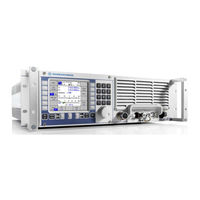
R&S M3SR 4100 Series Operating Manual (706 pages)
Software Defined Radios
Brand:
R&S
| Category:
Radio
| Size: 19.98 MB
Table of Contents
Table of Contents
16
1 User Information
49
Table 1.1 Applicable Software and Software Options (Option Keys)
49
Figure 1.1 R&S M3SR Series 4100 Radio (Front View)
50
General Features
50
Explanation of Models
52
Required Personnel
52
Design
53
Figure 1.2 R&S M3SR Series 4100 Radio, E.g. Transceiver (Top View Without Cover, Example)
54
Functioning of E.g. Receiver / Exciter
56
General Data
57
Required Power Supply
58
Required Power Supply for Receiver
58
Figure 1.3 R&S IN4190 Power Supply
59
Required Power Supply for Receiver / Exciter or PMU
59
Table 1.2 Available Power Supply Models
60
Figure 1.4 R&S IN4000A Power Supply
61
Communication Capabilities
62
Required Power Supply for Transceiver
61
Table 1.3 Signal Modulations
62
Voice Communication
62
Data Communication
63
Radio Control
64
Figure 1.6 Radio with Additional Remote Control Unit
65
Radio with Several Control Units
66
Figure 1.7 Radio with Built-In Control Unit and with Two Remote Control Units
67
Several Radios and Control Units in a Network
68
Figure 1.5 Radio with Built-In Control Unit
69
Figure 1.8 Several Radios and Remote Control Units in a Network (Example)
69
2 Getting Started
71
Packing
71
Unpacking and Checking
71
Unpacking, Checking, Packing, Transport and Storage
71
Storage
72
Installation and Removal
73
Figure 2.1 Installation into a 19" Rack, Example
74
Transport
72
Removal
75
Rear Cabling
76
Rear Cabling for Receiver
76
Figure 2.2 Rear Connectors of Receiver
77
Rear Cabling for Receiver / Exciter
78
Figure 2.3 Rear Connectors of Receiver / Exciter
79
Rear Cabling for Transceiver
80
Figure 2.4 Rear Connectors of Transceiver
81
Rear Cabling for Power Management Unit
82
Figure 2.5 Rear Connectors of Power Management Unit
83
Figure 2.6 Front Cabling
85
Front Cabling
85
System Cabling
86
System Cabling for Receiver / Exciter
86
Figure 2.7 Cabling between R&S GX4100A/D, R&S VK4190 and R&S IN4190
87
System Cabling for Transceiver
89
Figure 2.8 System Cabling for Transceiver
90
System Cabling for HF Broadband System
91
Switching the Radio on
93
Figure 2.10 Switching the Radio with Built-In Control Unit on
94
Switching on
95
Automatic Update of Modules
97
Figure 2.11 Example for the Automatic Update Process of a Frontend
98
Figure 2.12 Switching the Radio off
100
Switching the Radio off
100
Figure 2.13 Switching the Radio with Built-In Control Unit off
101
Basic Configuration of the Radio
102
Table 2.1 Default IP Settings of a Radio
102
Changing Radio IP Settings Using a Built-In Control Unit
103
Changing Radio IP Settings Using Upd32.Exe Tool
105
Figure 2.14 Radio IP Settings (Example)
105
Figure 2.15 Changing Radio IP Settings Using the Upd32.Exe Tool
106
Figure 2.16 Upd32: Select 'LAN Settings Via Ethernet
108
Figure 2.17 Upd32: Select Targets for Ethernet Communication Dialog (Example)
108
Figure 2.18 Upd32: LAN Setting Dialog (Example)
109
Figure 2.19 Upd32: Finish the Update
109
Basic Configuration of the Control Unit
110
Table 2.2 Default IP Settings of Control Unit
110
Figure 2.20 Control Unit IP Settings
112
Figure 2.21 Radio IP Address List of Control Unit
113
Example Configuration
114
Figure 2.22 Example Configuration
114
Radio Front Panel
122
Figure 3.4 Front Panel
122
3 Operation
117
Figure 3.1 Radio with Local Control Unit
117
Overview
117
Figure 3.2 Radio Backplane with Interfaces
118
Figure 3.3 Radio and Remote Control Unit Connected Via LAN
119
Operating Concept
121
Quick Erase
123
Table 3.1 General
124
Control Unit
126
Figure 3.5 Control Elements of R&S GB4000C Control Unit
126
Graphical User Interface Design
127
Leds
127
Menu Page Design
128
Icons and Symbols
129
Table 3.3 Icons
129
Table 3.4 Symbols
130
Figure 3.7 Example of a Softkey
132
Softkeys
132
Figure 3.8 Example of a Listbox
133
Table 3.5 Toggle Softkeys
133
Table 3.6 Listbox Softkeys
133
Figure 3.9 Example of an Editor
134
Table 3.7 Editor Softkeys
134
Table 3.8 Navigation Softkeys
135
Figure 3.10 Menu Number and Title
136
Menu Organization
136
Table 3.9 Editor Softkeys
136
Figure 3.11 Menu Numbering
137
Table 3.10 Menu Organization, Numbering and Titles
138
Table 3.2 Phone
139
Menu Tree
141
Table 3.11 Domains and Parameters
141
Figure 3.12 Menu Tree in Fixed Frequency Operation
142
Navigation Within the Menu Tree
143
Table 3.12 Navigation Softkeys
143
Figure 3.13 Position of Softkey 'Previous' (Example)
144
Table 3.13 Navigation Buttons
144
Control and Monitoring of Radio and Control Unit
145
Home Menu (0001)
145
Connecting to Radio
146
Figure 3.14 Home Menu, Not Connected
146
Figure 3.15 Selecting Remote Radio
147
Figure 3.16 Home Menu, Connecting to Radio
148
Figure 3.17 Example: Home Menu Connected, Active Communication Mode Is Fixed Frequency
149
Disconnecting from Radio
150
Figure 3.18 Connection Lost
150
Figure 3.19 Radio Access Rights
151
Session Types and Access Rights
151
Figure 3.20 Example: Three Monitoring Sessions
152
Figure 3.21 Example: Radio Grants a Fixed Session
153
Figure 3.22 Example: Radio Denies an Advanced Session
154
Table 3.14 Session Types
155
Figure 3.23 Selecting a Session
156
Figure 3.24 Session Indication in Menu Header
157
Communication Mode Menus
158
Figure 3.25 Connection Denied
158
Figure 3.26 Navigation Softkeys to Communication Mode Submenus
159
Preset Page
160
Figure 3.27 Preset Page Selection (Example)
161
Figure 3.28 Fill Gun Navigation Softkey (Example)
162
Fill Gun
162
Figure 3.29 Maintenance Navigation Softkey (Example)
163
Radio Maintenance
164
Figure 3.30 Menu Tree: Radio Maintenance
165
Menu Radio MTC 1/7 (3001)
166
Table 3.15 Softkeys in Menu Radio MTC 1/7 (3001)
167
Maintenance Menus
163
Figure 3.32 Menu 3011: Radio Error List (Example)
171
Menu Radio Error List (3011)
171
Table 3.16 Softkeys in Menu Radio Error List (3011)
172
Figure 3.33 Menu 3012: Radio Error Details (Example)
173
Menu Radio Error Details (3012)
173
Table 3.17 Softkeys in Menu Radio Error Details (3012)
174
Figure 3.34 Menu 3021: Radio Inventory of Installed Modules (Example)
175
Menu Radio Inventory (3021)
175
Figure 3.35 Menu 3021: Radio Inventory of Firmware Versions (Example)
176
Table 3.18 Softkeys in Menu Radio Inventory (3021)
177
Figure 3.36 Menu 3022: Radio Inventory Details (Example)
178
Radio Inventory Details (3022)
178
Figure 3.37 Menu 3022: Radio Inventory Details (Empty)
179
Menu PMU (3031)
180
Overview over All Possible Modes
181
Figure 3.38 Menu 3031: PMU, E.g. 4 Kw System
182
Figure 3.39 Menu 3031: PMU, E.g. 2 Kw System
183
Menu Split Site 1/2 (3041)
184
Table 3.19 Supported Devices (Split Site System)
184
Figure 3.40 Menu 3041: Split Site 1/2
185
Menu Split Site 2/2 (3042)
186
Softkey 'Disconnect'
186
Menu Split Site 2/2 (3042)
187
Menu Radio MTC 2/7 (3002)
190
Table 3.20 Softkeys in Menu Radio MTC 2/7 (3002)
191
Menu Radio MTC 2/7 (3002)
192
Menu Voip 1/2 (3061)
195
Menu Voip 2/2 (3062)
196
Figure 3.45 Menu 3003: Radio MTC 3/7 3003
198
Menu Radio MTC 3/7 (3003)
198
Table 3.21 Softkeys in Menu Radio MTC 3/7 (3003)
198
Figure 3.46 Menu 3004: Radio MTC 4/7: Valid Option Key
202
Menu Radio MTC 4/7 (3004)
202
Figure 3.47 Menu 3004: Radio MTC 4/7: Invalid Option Key
203
Figure 3.48 Menu 3004: Radio MTC 4/7: Response Option Key
203
Figure 3.49 Option Key Editor
205
Figure 3.50 Option Key Details Message Box (Example)
206
Menu Radio MTC 5/7 (3005)
207
Menu Radio MTC 5/7 (3005)
208
Table 3.22 PTT Crossreference List
208
Table 3.23 Softkeys in Menu Radio MTC 5/7 (3005)
209
Figure 3.52 Menu 3006: Radio MTC 6/7
210
Menu Radio MTC 6/7 (3006)
210
Table 3.24 Softkeys in Menu Radio MTC 6/7
211
Figure 3.53 Menu 3007: Radio MTC 7/7
212
Menu Radio MTC 7/7 (3006)
212
Table 3.25 Softkeys in Menu Radio MTC 7/7
212
Control Unit Maintenance
213
Figure 3.54 Menu Structure of Radio Maintenance Domain
214
Control Unit MTC 1/4 (4001)
215
Figure 3.55 Menu 4001: CU MTC 1/4
215
Table 3.26 Softkeys in Menu CU MTC 1/4 (4001)
216
Control Unit Error List (4011)
219
Figure 3.56 Menu 4011: CU Error List (Example)
219
Table 3.27 Softkeys in Menu CU Error List (4011)
220
Control Unit Error Details (4012)
221
Figure 3.57 Menu 4012: CU Error Details
221
Table 3.28 Softkeys in Menu CU Error Details (4012)
221
Control Unit Inventory (4021)
222
Figure 3.58 Menu 4021: CU Inventory
222
Table 3.29 CU Inventory Types
223
Table 3.30 Softkeys in Menu CU Inventory (4021)
223
Control Unit Inventory Details (4022)
224
Figure 3.59 Menu 4022: CU Inventory Details (Example)
224
Table 3.31 Softkeys in Menu CU Inventory Details
225
Control Unit Keyboard Test (4031)
226
Figure 3.60 Menu 4031: CU Keyboard Test
226
Control Unit MTC 2/4 (4002)
227
Figure 3.61 Menu 4003: CU MTC 2/4
227
Table 3.32 Softkeys in Menu CU MTC 2/4
228
Control Unit MTC 3/4 (4003)
230
Figure 3.62 Menu 4003: CU MTC 4/3 (Example)
230
Figure 3.63 Listbox Connect to Radio
231
Figure 3.64 Radio IP Address List (Example with Local Radio)
232
Figure 3.65 Listbox Connect to Radio
233
Table 3.33 Softkeys in Menu CU MTC 3/4
234
Control Unit MTC 4/4 (4004)
236
Figure 3.66 Menu 4004: CU MTC 4/4
236
User Level
238
Figure 3.67 Menu 4001: CU MTC 1/4
239
Figure 3.68 User Level Editor
239
Figure 3.69 Unlock
241
Figure 3.70 Menu Tree: Fixed Frequency
242
Fixed Frequency
242
Fixed Frequency Menu Tree
242
Figure 3.71 Home Menu: Fixed Frequency, E.g. F3E Operation Mode (Rx Mode)
243
Fixed Frequency Home Menu
243
Figure 3.72 Home Menu: Fixed Frequency, E.g. F3E Operation Mode (Tx Mode)
244
Fixed Frequency Operational Menus
245
Table 3.35 Menu Structure as Function of Modulation Mode
246
Storing Current Settings
250
Recalling Settings
252
Selecting the Signal Squelch Subtone Frequency
254
Changing the RSSI Squelch Sensitivity
255
Selecting the Squelch Type
256
Changing the Syllabic Squelch Threshold
257
Switching the Rx Preamplifier on and off
258
Switching the Automatic Gain Control on or off
259
Changing the AGC Threshold
260
Changing the MGC Level
261
Changing the Release Time
262
Changing the Receiver Filter Bandwidth
263
Changing the Modulation Mode
264
Changing the Clarifier Frequency
265
Changing the Frequency
266
Changing the Editor Mode
267
Changing the Frequency
267
Switching the VOX Signal Source
269
Switching the Voice Compressor on or off
270
Selecting the Noise Blanker Type
271
Selecting the Notch Filter Speed
272
Changing the Passband Tuning Frequency
273
Selecting the Power Level
274
Starting ATU Tuning
275
Changing the BFO Frequency for A1A
276
Changing the Delta Frequency
277
Selecting the Data Link Mode
278
Switching the Multitone Function on or off
279
Changing the PEP (Peak Envelope Power) to Average Power Factor
280
Selecting the F1D Baud Rate
281
Changing the F1D Transmitter / Receiver Signal Polarity
282
Changing the Frequency Shift for F1D
283
TTY RUN/STOP Selection
284
Figure 3.73 Menu 1121: FF CFG 1/2
285
Fixed Frequency Configuration Menus
285
Figure 3.74 Menu 1122: FF CFG 2/2
286
Starting ATU Learning
287
Switching ATU Silent Tuning on or off
288
Bypassing the ATU
289
Changing the A1A Holdtime
290
Switching Environment Shore or Ship
291
Changing the ATU Learning Range
292
Changing the Default Release Times
293
Changing the Squelch Hangover Time
294
Changing the Signal Squelch Mode
295
Changing the VOX Holdtime
296
Changing the VOX Sensitivity
297
Activating / Deactivating SELCAL
298
Introduction
299
Radio Configuration with Pre-Configured Parameters
299
Figure 3.75 Available Preset Page after Delivery from Factory
300
Procedures for Loading the Configuration into the Radio
301
Download from PC into Radio Via Serial Cable
302
Figure 3.76 Loading Configuration to Radio Via Serial Cable
303
Figure 3.77 Download in Progress (Example)
305
Download from Fillgun into Radio
307
Figure 3.78 First Step: Loading Configuration to Fillgun
307
Figure 3.79 Second Step: Loading Configuration from Fillgun into Radio
309
Figure 3.80 Download in Progress (Example)
311
Download Via LAN
312
Figure 3.81 Loading Configuration to Radio Via LAN
313
Basics of Fixed Frequency Scanning
315
Figure 3.82 State Diagram of the Scanning Feature
315
Fixed Frequency Scanning
315
FF SCAN Menu Tree
316
Figure 3.83 Menu Tree: FF SCAN
316
FF SCAN Home Menu
317
Figure 3.84 Home Menu: FF SCAN
317
FF SCAN Menu
318
Figure 3.85 Menu 1115: FF SCAN 1/2 (Frequency Scan)
318
Figure 3.86 Menu 1115: FF SCAN 1/2 (Channel Scan)
318
Figure 3.87 Menu 1125: FF SCAN 2/2
319
Storing Current Settings
320
Changing the Syllabic Squelch Threshold
321
Selecting the Signal Squelch Subtone Frequency
322
Changing the RSSI Squelch Sensitivity
323
Selecting the Squelch Type
324
Changing the Frequency Scanning Parameters
325
Lock Frequency or Channel
326
Changing the Modulation Mode
327
Selecting the Scan Action
328
Table 3.36 Possible States of FF Scanning
329
Selecting the Scan Type
331
Changing the Dwell Time
332
Changing the Hold Time
333
Channel List
334
Priority Channel
335
4 Operation in Special Communication Modes
337
Introduction
337
Figure 4.1 Valid Option Keys in Menu Radio MTC 4/7 (Example)
338
Preparations
338
Automatic Link Establishment 2 Nd Generation (ALE-2G)
339
Basics of ALE-2G
339
Link Quality Analysis and Automatic Link Establishment
339
Message Transmission
339
Selective Call and Handshake
339
ALE-2G Calls
340
ALE-2G Missions and Database
341
Table 4.1 User Unique Functions
341
Basics of ALE-2G LP
342
Table 4.2 Time Uncertainty Definition
342
User Unique Functions
341
Achieving Network Synchronism
343
Maintaining Network Synchronism
344
Table 4.3 Time to Keep Radio (Net Station) Synchronized
344
Changing the Time Server
345
ALE-2G Menu Tree
346
Figure 4.2 Menu Tree: ALE-2G
347
ALE-2G Home Menus
348
Figure 4.3 Home Menu: ALE-2G (Listening, Rx Mode)
348
Figure 4.4 Home Menu: ALE-2G (Listening, Tx Mode)
349
ALE-2G Operational Menus
350
Figure 4.5 Menu 1211: ALE OP 1/2 (ALE-2G)
350
Figure 4.6 Menu 1212: ALE OP 2/2 (ALE-2G)
351
Selecting the Scan Groups
352
Selecting the Address for Individual Call
353
Selecting the Address for Net Call
354
Selecting the Tx Message
355
Selecting the Link Mode
356
Terminating a Link
357
Linked Stations List
358
Initiating a Link Via MMI
359
Selecting the Scan Rate
360
Selecting the Active Channel for 'Fix' Operation
361
Selecting the Self Address
362
ALE Group Call Address Selection and Address Editor
363
Adding an Individual Address
365
Selecting the Next Call to be an any or All Call
366
Displaying Received Rx Messages
367
Selecting the Power Level
368
Starting ATU Learning for ALE Channels
369
ALE 2G Configuration Menus
370
Figure 4.7 Menu 1221: ALE CFG 1/3 (ALE-2G)
370
Figure 4.8 Menu 1222: ALE CFG 2/3 (ALE-2G)
371
Figure 4.9 Menu 1223: ALE CFG 3/3 (ALE-2G)
372
Switching the Acceptance of an All/Any/Wildcard Call on or off
373
Switching the Popup for Received AMD Messages on or off
374
Switching the LQA Request on or off
375
Switching the LQA Report on or off
376
Selecting the Weight of a New LQA Event
377
Bypassing the ATU
378
Switching the Default Link Mode for Voice on or off
379
Switching the User Unique Function on or off
380
Changing the Response Timeout
381
Changing the LBT Timeout
382
Changing the Link Timeout
383
Switching the Sounding on or off
384
Changing the Sounding Interval
385
Changing the Date and Time
386
Switching Passive Time Acquisition on or off
387
Enabling or Disabling Unprotected Time Request (Random Value)
388
Switching Protected Coarse Time Request (Time Lag < 1 Min) on or off
389
Switching Protected Fine Time Request (Time Lag < 2 S) on or off
390
Designating the Local Station Time Server or Net Station
391
Changing the SINAD Threshold
392
Switching the Acceptance of Calls with a Lower Linking Protection Level on or off
393
Changing the Time Request Interval
394
Entering the Key
395
Selecting the Protection Level
396
Common ALE-2G and ALE-3G FF and HF Modem Menus
397
ALE-2G/ALE-3G FF Operational and Configuration Menus
398
Figure 4.10 Menu 1111: FF OP1/2 (ALE-2G), E.g. A1A
398
Figure 4.11 Menu 1112: FF OP2/2 (ALE-2G), E.g. A1A
399
Figure 4.12 Menu 1122: FF CFG 1/1 (ALE-2G/ALE-3G)
400
ALE-2G/ALE-3G HF Modem Operational and Configuration Menus
401
Figure 4.13 Menu 1511: HFM OP 1/1 (ALE-2G)
401
Figure 4.14 Menu 1521: HFM CFG 1/1 (ALE-2G/ALE-3G)
402
Achieving Network Synchronization
403
Automatic Link Establishment 3 Rd Generation (ALE-3G)
403
Basics of ALE-3G
403
Improved LQA Mechanism and Automatic Channel Selection
403
ALE-2G Concurrent Operation in ALE-3G
404
ALE-3G Calls
404
ALE-3G Missions and Database
404
Optimized Transfer of IP Packets
405
Voice Priority over IP Data
405
Automatic Link Maintenance (ALM)
406
Communication Security (COMSEC)
406
Last Ditch Voice (LDV)
406
Secure Digital Voice (SDV)
406
ALE-3G Menu Tree
407
Figure 4.15 Menu Tree: ALE-3G
408
ALE-3G Home Menus
410
Figure 4.16 Home Menu: ALE 3G (Listening, Rx Mode)
410
Figure 4.17 Home Menu: ALE-3G (Listening, Tx Mode)
411
ALE-3G Operational Menus
412
Figure 4.18 Menu 1211: ALE OP 1/2 (ALE-3G)
412
Figure 4.19 Menu 1212: ALE OP 2/2 (ALE-3G)
413
Selecting the Address for Multicast Call
414
Selecting the Link Mode
415
Selecting the Type of Link Setup
416
Selecting the Call Channel Type
417
Selecting the Address for Broadcast Call
418
Playback a Received Last Ditch Voice Message
419
ALE-3G Configuration Menus
420
Figure 4.20 Menu 1221: ALE CFG 1/4 (ALE-3G)
420
Figure 4.21 Menu 1222: ALE CFG 2/4 (ALE-3G)
422
Display of the Packet Aggregation Setting (ON/OFF)
423
Figure 4.22 Menu 1223: ALE CFG 3/4 (ALE-3G)
424
Figure 4.23 Menu 1224: ALE CFG 4/4 (ALE-3G)
425
Switching the Acceptance of a Broadcast Call on or off
426
Switching the Acceptance of an ALE-2G Call on or off
427
Changing the Link Timeout for Analog Voice/Ff Links
428
Changing the Timeout for Data Links
429
Deleting the LQA Table
430
Switching the Priority Based Session Management on or off
431
Selecting the Xdl Mode
432
Table 4.4 Dependency of Packet Size on Selected Traffic Mode
433
Selecting the HDL Number of Packets Per Tx Frame
434
Selecting the LDL Number of Bytes Per Tx Frame
435
Changing the Number of Retries for Initiated Link Setup
436
Switching the Acceptance of LQA Exchange on or off
437
Address Selection for LQA Exchange
438
Switching the LQA Mode on or off
439
Switching Passive Time Acquisition on or off
440
Switching the Time Synchronization on or off
441
Switching the Occupancy Detection on or off
442
Table 4.5 Waveform Message
443
Selecting the Voice Priority over IP Data Function
444
Selecting the Time Source
445
Changing the Time Request Interval
446
Switching the ALE-3G Linking Protection on or off
447
Switching the ALE-3G ALM Enable on or off
448
Changing ALM Threshold for Voice/Ff Links
449
Changing ALM Threshold for Data Links
450
Changing ALM Channel Usage
451
Changing ALM Interval for Voice Links
452
Changing ALM Execution Delay for Voice Links
453
Changing ALM Interval for LLE
454
Changing ALM Interval for Data Links
455
Changing ALM Interval for Link Quality Monitoring
456
Changing ALM Relink Mode
457
Changing ALM Execution Mode
458
Basics of HF Modem
459
HF Modem
459
Figure 4.24 Menu Tree: HF Modem
460
HF Modem Menu Tree
460
Figure 4.25 Home Menu: HF Modem (Rx Mode)
461
HF Modem Home Menu
461
Figure 4.26 Home Menu: HF Modem (Tx Mode)
462
Figure 4.27 Menu 1511: HFM OP 1/1
463
HF Modem Operational Menu
463
Changing the Rx and Tx Data Rate
464
Table 4.6 Data Rates and Interleaver Setting Dependencies on the Waveform
465
Changing the Rx and Tx Interleaver Length
467
Terminating the Data Transmission
468
HF Modem Configuration Menu
469
Changing the Modem Deacquire Limit
470
Changing the Modem Doppler Tracking Time
471
Enabling the Modem Synchronization on Data Function
472
Changing the Maximal Message Block Length
473
Changing the Modem Tx Level Control Blocks
474
Switching the EOM Flag
475
Selecting the HF Modem Waveform
476
Selecting the Asynchronous Modem Operation Mode
478
Link SW
479
Figure 4.29 Menu FF OP 1/2 in Modulation Mode B7D and Link 11 (Option)
480
Basics of Secure Digital Voice
481
Figure 4.30 Architecture of the SDV Communication Mode (Principle)
481
Secure Digital Voice
481
Figure 4.31 Menu Tree: SEC VOICE
483
SEC VOICE Menu Tree
483
Figure 4.32 Home Menu: SEC VOICE (Rx Mode)
484
SEC VOICE Home Menu
484
Figure 4.33 Home Menu: SEC VOICE (Tx Mode)
485
Changing the Frequency for SDV Communication
486
Changing the Power Level for SDV Communication
486
SEC VOICE Operational Menu
486
Switching the VOX Signal Source for SDV Communication
487
Tuning the Antenna
487
Changing the SDV Vocoder Mode
488
Selecting the Active COMSEC Key for SDV Communication
489
Changing the VOX Holdtime for SDV Communication
490
Changing the VOX Sensitivity for SDV Communication
490
SEC VOICE Configuration Menus
490
Editing a User-Defined COMSEC Key for SDV Communication
491
Basics of SECOM-H
493
Secom-H
493
SECOM-H Net
493
COMSEC and TRANSEC
494
Time Synchronization
494
Linking
495
Free Hopset Search
496
SECOM-H Menu Tree
497
Figure 4.36 Menu Tree: SECOM-H
498
Figure 4.37 Home Menu: SECOM-H (Rx Mode)
499
SECOM-H Home Menu
499
Figure 4.38 Home Menu: SECOM-H (Tx Mode)
500
Figure 4.39 Menu1311: SECOMH OP 1/1
501
SECOM-H Operational Menu
501
Addressing Different Link Types
502
Selecting the Service Mode
503
Voice_O_Ipd
504
Initiating a Free Hopset Search
505
Switching the Advanced Hopset on or off
506
Selecting the Search Pattern Time
507
Table 4.7 Dependency of Tolerable Deviation on Selected Search Pattern
507
Terminating a Link
508
Selecting the Power Level
509
Initiating Time Acquisition
510
Switching the VOX Signal Source
511
Starting ATU Learning for SECOM-H Hopset
512
Selecting a Hopset
514
Selecting a Keyset
515
SECOM-H Configuration Menus
516
Figure 4.41 Menu 1322: SECOMH CFG 2/2
517
Switching the Time Beacon Mode on or off
518
Defining a Radio as a Time Reference Unit
519
Switching the Free Hopset Search Mode on or off
520
Changing the Number of Channels in an Advanced Hopset
521
Selecting the Waveform
522
Selecting the Data Rate for SECOM-H Transmission
523
Table 4.8 Dependency of Waveform/Air Data Rates on Data Rates/Modes of Data Term 1
524
Selecting the Interleaving Length
525
Bypassing the ATU
526
Configuring the Vocoder
527
Changing the SECOM-H Date and Time
528
Selecting the Time Source
529
Editing a User Hopset
530
Figure 4.42 Hopset Folder Main Menu in CFG 2/2 Menu
530
Figure 4.43 Keyset Folder Main Menu in CFG 2/2 Menu
531
Defining a New Hopset
532
Inserting a User Hopset Subband
533
Editing a User Hopset Subband
536
Deleting a User Hopset Subband
539
Editing a User Keyset
541
Figure 4.44 Keyset Folder Main Menu in CFG 2/2 Menu
541
Further Settings Are Relevant for SECOM-H Operation
545
Roles of Radios Supporting GPS Reporting
552
Types of GPS Transmission
553
Configure Periodic (Timer Initiated) Transmission of GPS Information
554
5 Services
547
Introduction
547
Basics of GPS Reporting
548
GPS Reporting
548
Figure 5.1 GPS Reporting System
549
Immediate (Unscheduled) Transmission
555
Addressing of GPS Transmissions
556
General Requirements and Valid Combinations of GPS Reporting Features
558
Table 5.1 Requirements and Valid Combinations of GPS Reporting
558
SECOM-H Specifics of GPS Reporting (Option)
560
ALE-3G Specifics of GPS Reporting (Option)
561
Figure 5.2 Menu 1151: GPS OP (Without GPS Reporting)
562
GPS Operational Menus
562
Figure 5.3 Menu 1351: GPS OP (GPS Reporting Enabled)
563
Display of the GPS Position
564
Figure 5.4 Own GPS Position
565
Display of the GPS Reporting Data
566
Figure 5.5 GPS Reporting Data
566
Display the GPS Position Accuracy
568
Selecting the Role of a Participant
569
Table 5.2 Influence of the Currently Selected Role
569
Initiating a GPS Position Information Transmission (Push, Immediately)
570
Initiating a GPS Position Information Transmission (Push, Scheduled)
571
Initiating a GPS Information Request (Pull, Immediately, as Controller Feature)
572
Initiating a GPS Information Request (Pull, Scheduled, as Controller Feature)
573
Initiating an Auto Push List Request Transmission (as Controller Feature)
574
List of Received GPS Position Information
576
Switching the Controller Reports Position as Controller Feature on or off
577
Table 5.3 Influence of the Currently Selected CRP Status
577
Basics of IP over Air (Ipoa)
578
IP over Air (Ipoa)
578
Figure 5.6 Network Infrastructure
579
Figure 5.7 Radio IP Interfaces
581
General Constraints
582
Recommendations for the Transport Layer
582
Recommended Adjustments for TCP
583
Special IP Services
584
Table 5.4 Priority, IP Mapping (Protocol / Port) and ARQ
584
Table 5.5 Send Buffer and Thresholds
585
ARQ Functionality
586
ALE 3G / Xdl ARQ Functionality
587
Fastlink Mode (FLM)
588
Figure 5.8 FLM Connection
589
FLM Control
591
Table 5.6 FLM States
591
Table 5.7 FLM Activities
592
Figure 5.9 State Transitions (Graphic Representation)
593
Table 5.8 State Transitions (Events)
594
Table 5.9 State Transitions (Rebroadcast)
594
Fastlink over Rebroadcast
595
Figure 5.10 Fastlink over Rebroadcast
596
Rebroadcast / Relay Mode
598
Figure 5.12 Configuration of IP Address for Relay/Rebroadcast Mode on MMI
600
Digital Voice Transfer
601
Figure 5.13 Rebroadcast Scenario
602
Propagation and Routing
603
Figure 5.14 Local Voice for Rebroadcast Mode
604
Figure 5.15 Local Voice Selection on MMI
605
Local Voice Forwarding
606
Figure 5.16 Voice Forwarding Selection on MMI
607
Relay Mode
608
Figure 5.17 Relay Scenario
609
IP Routing
610
Figure 5.18 Relay IP Broadcast Selection on MMI
611
Relay IP Broadcast Forwarding
612
Figure 5.19 Local Voice Selection on MMI
613
Ipoa Configuration Menus
615
Figure 5.21 Menu 1332: Ipoa CFG 2/2
616
Changing the Radio Air Interface IP Address
617
Changing the Radio Air Interface Netmask
618
Changing the PPP IP Interface Address
619
Remote Control Via PPP
620
Changing the Rebroadcast IP Address
621
Switching the Voice Forward Mode for Rebroadcast on or off
622
Switching the Local Voice Mode for Rebroadcast on or off
623
Switching the Relay IP Mode for Broadcast on or off
624
Changing the Operation Mode
625
Changing the Connection Mode
626
Editing the Routing Table
627
Figure 5.22 Ipoa Unicast Routing Menu
628
Editing the Multicast Routing Table
630
Figure 5.23 Ipoa Multicast Routing Menu
632
Multicast Routing Table .......................................... 5.84
633
Basics of Message Service
635
Message Service
635
Message Size
635
Storage Strategy
635
IP-Based Interface for External Applications
636
Message Addressing
636
Participant Selection List (R&S M3TR Only)
636
Prerequisites
636
Indication of a New SDM in the Waveform- Specific Operational Menu (R&S M3TR Only)
637
Figure 5.24 Menu 1341 Msg Service 1/2, SDM Message Inbox
638
Menu Structure
638
Inbox
639
Drafts Folder
641
Figure 5.25 Menu 1341 Msg Service 1/2, Text Editor
642
Text Editor
642
Alert Messages
644
Figure 5.27 Menu 1342 Msg Service 2/2, Alert Inbox
645
Alert Sending
646
Basics of Voice over IP (Voip)
647
Figure 5.28 IP-Based Remote Operation Application
647
Voice over IP (Voip)
647
Configuration Scenarios
648
Figure 5.29 Connecting a Radio Network to a Voip Network
648
Figure 5.30 CNR - Change of the Radio Cell
651
Figure 5.31 SIP Domain Connect over Air
653
Call Session
655
General Constraints
655
Phone Service
656
Scenario: Call Session between a Radio Network and a Voip Telephone
657
Figure 5.32 Connection between a Radio Network and a Voip Telephone
658
Figure 5.33 Menu 1255: PHONE
660
PHONE Menu
660
Entering the Phone Number for a Manual Dial
661
Selecting the Phone Number for a Speed Dial (Using the Phone Book)
662
Accept an Incoming Call
663
Terminating an Active Call Session
664
SIP - Useful Information for System Integration
665
Session Signalling
665
Figure 5.34 SIP and Proprietary Signalling (DIAL)
666
Figure 5.35 SIP and Proprietary Signalling (ACCEPT, Gateway Radio)
667
Figure 5.36 SIP and Proprietary Signalling (ACCEPT, Endpoint Radio)
668
SIP Signalling
668
Proprietary Signalling Inside the Radio Network
669
Call Initiated from Radio Network
670
6 Malfunction
671
Visual Inspection
671
Fuses F1 / F2 - Change
672
Troubleshooting
673
Radio Built-In Test
673
Figure 6.2 GO LED on Radio Front Panel and GO LED on Control Panel Switched off in Case of Error (Example)
674
Warnings
674
Power-On Built-In Test (PBIT)
675
Figure 6.3 Menu Radio MTC 1/7 Indicating an Error (Example)
676
Figure 6.4 Menu Radio Inventory Indicating a Defective Module (Example)
677
Figure 6.5 Menu Radio Error List (Example)
677
Continuous Built-In Test (CBIT)
678
Initiated Built-In Test (IBIT)
679
Control Unit Built-In Test
680
7 Maintenance
681
Figure 7.1 Label, E.g. XK 4115: Date of Battery Installation
682
Scheduled Maintenance
682
Figure 7.2 Fixing the Cover to the Front Panel
683
Calibration Procedure
684
Required Test Equipment
684
Synthesizer Calibration
684
Figure 7.3 Radio Maintenance Menu, Calibration Not Allowed
685
Figure 7.4 Radio Maintenance Menu, Calibration Possible
686
Figure 7.5 Calibration Running
687
Figure 7.6 Calibration Failed
688
Figure 7.7 Calibration Successful
689
Possible Errors During Calibration
690
Care
691
Care, Cleaning
691
Cleaning
691
Table 7.1 List of Materials
691
Retouching the Paint Work
692
Technical Data
693
External Interfaces
694
Remote Control
695
8 Technical Information
693
9 Drawings
697
Figure 9.1 Cabling between R&S GX4100A/D, R&S VK4190; R&S IN4190 and R&S BV4190
698
Figure 9.2 Cabling between R&S GX4100A/D, R&S VK4190; R&S IN4190 and R&S FK4190M
700
Figure 9.3 Cabling between R&S GX4100A/D, R&S VK4190; R&S IN4190 and R&S FK4190X
702
Figure 9.4 Control and Display Elements
704
Advertisement
Advertisement
Related Products
R&S MR4100E
R&S MR4100X
R&S MR4100G
R&S MR4100G-B
R&S Categories
Measuring Instruments
Test Equipment
Portable Generator
Power Supply
Accessories
More R&S Manuals
Login
Sign In
OR
Sign in with Facebook
Sign in with Google
Upload manual
Upload from disk
Upload from URL