Table of Contents
Advertisement
SIMATIC NET
IE/AS−INTERFACE LINK PN IO
as of hardware version 1, as of firmware version V2.0
Manual
Release 08/2018
C79000−G8976−C216−03
Preface, Contents
Technical Description,
Installation Guidelines, Operation
Procedure − Configuration
Getting Started − Commissioning
with STEP 7
Keypad and Display
Display / WBM Configuration
Configuring with STEP 7 or a
GSDML File
Data Exchange between
PROFINET IO Controller and
AS−i Slave
Using the Data Record Interface
Diagnostics
Dealing with Problems /
Error Displays
Anhang
AS−Interface Protocol Implemen−
tation Conformance Statement
References
Notes on the CE Label
Glossary
Index
1
2
3
4
5
6
7
8
9
10
A
B
C
D
Advertisement
Table of Contents

Related Manuals for Siemens SIMATIC NET IE/AS-INTERFACE LINK PN IO


Summary of Contents for Siemens SIMATIC NET IE/AS-INTERFACE LINK PN IO
- Page 1 Preface, Contents Technical Description, Installation Guidelines, Operation Procedure − Configuration Getting Started − Commissioning SIMATIC NET with STEP 7 Keypad and Display IE/AS−INTERFACE LINK PN IO Display / WBM Configuration as of hardware version 1, as of firmware version V2.0 Configuring with STEP 7 or a GSDML File Manual...
- Page 2 Classification of the Safety−Related Notices This manual contains notices which you should observe to ensure your own perso- nal safety, as well as to protect the product and connected equipment. These noti- ces are highlighted in the manual by a warning triangle and are marked as follows according to the level of danger: Danger indicates that death, severe personal injury will result if proper precautions are not...
-
Page 3: Technical Description
Siemens. This product can only function correctly and safely if it is transported, stored, set up, and installed correctly, and operated and maintained as recommended. - Page 4 For ordering data of the documentation please refer to the catalogs or contact your local SIEMENS representative. Copyright E Siemens AG 2006 − 2008 All rights reserved Disclaimer The reproduction, transmission or use of this document or its contents is not We have checked the contents of this manual for agreement with the hard- permitted without express written authority.
- Page 5 Preface Purpose of the Manual This manual supports you when using the IE/AS-INTERFACE LINK PN IO module. The product name is also shortened to IE/AS-i LINK in the manual. It contains information about how PROFINET IO controllers can address AS-i actuators and AS-i sensors via this module.
- Page 6 You will find this symbol in Chapter 5 where it is used to identify the description of menu sequences on the display and keyboard. FAQs You will find FAQs on Siemens AS−i products on the Internet on the Service and Support pages of Industry Automation at the following address: http://support.automation.siemens.com/WW/view/en/10805888 as of hardware version 1, as of firmware version V2.0...
-
Page 7: Table Of Contents
Contents Preface ..............Contents . - Page 8 Contents 5.2.1 Navigation “System −> System Configuration” ....5.2.1.1 General ............5.2.1.2 Identification &...
-
Page 9: Contents
Contents 5.2.16.3 Automatic Addressing ..........6 Configuring with STEP 7 or a GSDML File . - Page 10 Contents 8.2.2.2 Get_Permanent_Parameter ........8.2.2.3 Write_Parameter .
-
Page 11: General Notes On Operation − Safety Warnings
1 Technical Description, Installation Guidelines, Operation This chapter... This chapter will familiarize you with the performance characteristics, basic functions and installation of the IE/AS-INTERFACE LINK PN IO master module. You will learn the following: S How to install the IE/AS-i LINK S Which display and control elements the IE/AS-i LINK provides. - Page 12 1 Technical Description, Installation Guidelines, Operation Warning ”WARNING” − Explosion Hazard − Do not disconnect while circuit is live unless area is known to be non-hazardous. ”WARNING” − Explosion Hazard − Substitution of components may impair suitability for Class I, Division 2 or Zone 2. This equipment is suitable for use in Class I, Division 2, Groups A, B, C, D;...
-
Page 13: Technical Description, Installation Guidelines, Operation
1 Technical Description, Installation Guidelines, Operation Uses of the Module PROFINET IO Device and AS-Interface Master The IE/AS-i LINK is both a PROFINET IO device and AS-Interface master: S IE/AS-i LINK connects the actuator-sensor interface with PROFINET IO. S Using the IE/AS-i LINK module, you can access the inputs and outputs of the AS-i slaves from PROFINET IO Depending on the slave type, you can access binary values and / or analog values. - Page 14 1 Technical Description, Installation Guidelines, Operation Features The IE/AS-INTERFACE LINK PN IO is a PROFINET device (complying with IEC 61158) and AS-Interface master (complying with the AS-Interface specification V3.0 according to EN 50 295) and allows transparent data access to the AS-Interface from PROFINET IO.
-
Page 15: Technical Specifications Of The Module
1 Technical Description, Installation Guidelines, Operation Technical Specifications of the Module The IE/AS-INTERFACE LINK module has the following technical data: Table 1-1 Technical Specifications Feature Explanation/Values AS-i cycle time 5 ms for 31 slaves with standard addressing 10 ms for 62 slaves with A/B addressing (The values apply for the possible full configuration of an AS-i network on the IE/AS-INTERFACE LINK 10 ms for inputs according to profile S-7.A.7... -
Page 16: Approvals
1 Technical Description, Installation Guidelines, Operation Table 1-1 Technical Specifications Feature Explanation/Values Relative humidity Max. 95% at +25°C Construction Type of protection IP 20 Dimensions (W x H x D) in mm 90 x 132 x 85.5 Weight approx. 380 g Receptacle for optional C-PLUG Full graphics display and 6 control buttons 128 x 64 pixels... - Page 17 1 Technical Description, Installation Guidelines, Operation Installation Guidelines and Installing the Module Caution Noise immunity / grounding To ensure the immunity of the IE/AS-INTERFACE LINK PN IO, the IE/AS-i LINK, the AS-i power supply unit and the power supply of the IE/AS-i LINK must be grounded according to the regulations.
- Page 18 1 Technical Description, Installation Guidelines, Operation Convection Make sure that you leave at least 5 cm clearance above and below the module to allow heat dissipation. Caution The DIN rail may only be installed horizontally. The IE/AS-i LINK must be mounted vertically to ensure the required heat dissipa- tion through the ventilation openings and at the top of the device.
-
Page 19: Installation Guidelines And Installing The Module
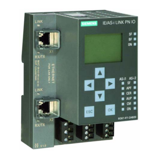
1 Technical Description, Installation Guidelines, Operation Front Panel − Access to all Functions Connection, Display and Control Elements On the front panel, you have access to all the connection, display and control elements of the IE/AS-i LINK module. C-PLUG (optional) Display LED “LINK”... -
Page 20: Connection Elements
1 Technical Description, Installation Guidelines, Operation Connection Elements Connectors The IE/AS-i LINK has the following connectors: S Two separate connectors for the AS-i cable (on double master) S One connector for alternative power supply 24 V DC (optional) and functional earthing S Two RJ-45 LAN connectors as independent switch ports connector 1... -
Page 21: Connectors For The As-I Cable(S) And Power Supply
1 Technical Description, Installation Guidelines, Operation 1.7.1 Connectors for the AS-i Cable(s) and Power Supply Caution When connecting up the module, keep to the installation guidelines in Section 1.5. Caution The IE/AS-INTERFACE LINK PN IO may only be connected when the AS-i power supply unit is turned off. - Page 22 1 Technical Description, Installation Guidelines, Operation Power Supply from the AS−Interface Caution The AS-i power supply unit used and the optional external power supply must provide an extra low voltage safely isolated from the mains supply. This safe isolation can be implemented according to the following requirements: VDE 0100 Part 410 = HD 384-4-4 = IEC 364-4-41 (as functional extra-low voltage with safe isolation) or VDE 0805 = EN60950 = IEC 950...
- Page 23 1 Technical Description, Installation Guidelines, Operation Note Functional earthing IE/AS-INTERFACE LINK PN IO has a connector for functional earthing. This connector is required if the integrated ground fault monitoring is used. It should be connected to the PE conductor with as little resistance as possible. LAN Connectors (PROFINET IO, PC with WBM) As connectors for PROFINET and a PC (or network) there are two RJ-45 jacks (recommendation: 90°...
-
Page 24: C-Plug (Configuration Plug)
1 Technical Description, Installation Guidelines, Operation C-PLUG (Configuration Plug) Area of Application The C-PLUG (order number: 6GK1 900-0AB00) is an optional exchangeable medium for saving the configuration and project engineering data of the basic device (IE/AS-i LINK) and the AS-i slaves. When powered down, the C-PLUG retains all data permanently. - Page 25 1 Technical Description, Installation Guidelines, Operation Function If an empty C-PLUG (as supplied) is inserted, all the configuration data of the IE/AS-i LINK is written to it when the device starts up. Changes to the configuration during operation are also written automatically to the C-PLUG. If the C-PLUG is inserted, the basic device automatically uses the configuration data of the C-PLUG.
- Page 26 1 Technical Description, Installation Guidelines, Operation Display and Control Elements LED Displays The following LED displays are located on the front panel of the IE/AS-i LINK: S Displays for the LAN connectors (separate for X1 and X2) − LINK: Connection to Ethernet partner −...
- Page 27 1 Technical Description, Installation Guidelines, Operation Meaning of the AS-i Line LEDs LED (color) Status Meaning SF (red) System fault The LED is lit when a diagnostic interrupt (entering state) was (line) triggered by the PROFINET IO controller in protected mode. APF (red) AS-i Power Fail This indicates that the voltage supplied to the AS-i cable by the AS-i...
-
Page 28: Display And Control Elements
1 Technical Description, Installation Guidelines, Operation Keypad The mode can be changed using the control buttons. You configure the underlying AS-i line interactively with the display using the control buttons. The following buttons are located on the front panel of the IE/AS-i LINK: Display The graphic display has a resolution of 128 x 64 pixels. -
Page 29: Settings When Using A Firewall
1 Technical Description, Installation Guidelines, Operation As soon as any entry is made using the keypad, the main menu appears allowing you to navigate through the menu structure. Figure 1-6 Display − Main Menu If you have selected an entry in the list (displayed inversely), a tooltip will appear after a brief time with further information on the entry (does not occur in the main menu). - Page 30 1 Technical Description, Installation Guidelines, Operation 1.11 Restrictions due to broadcast or multicast communication The IE/AS-i LINK PN IO is designed for operating on PROFINET networks where the configured participants are connected and communicate error-free. It is imperative to prevent high levels of broadcast or multicast communication on the PROFINET network.
- Page 31 1 Technical Description, Installation Guidelines, Operation as of hardware version 1, as of firmware version V2.0 IE/AS−INTERFACE LINK PN IO Release 08/2018 C79000−G8976−C216−03...
-
Page 32: Procedure − Configuration
2 Procedure − Configuration This chapter... This chapter provides you with an overview of the steps and procedures involved in configuring the IE/AS-i LINK. You will learn the basic steps leading to commissioning and the configuration options made available to you by the IE/AS-i LINK. -
Page 33: Configuration Options
2 Procedure − Configuration Configuration Options There are four basic configuration options that are described in later chapters. Configuration of the AS-Interface S Keypad/display (see Chapter 4) Local configuration, commissioning and diagnostics of the AS-Interface S Web Based Management (WBM) (see Chapter 5) Configuration, commissioning and diagnostics of the AS-Interface over a LAN attachment using a PG/PC with an Internet Browser You can change the configuration of the IE/AS-i LINK, check settings and... -
Page 34: Getting Started − Commissioning With Step 7
3 Getting Started − Commissioning with STEP 7 This chapter... This chapter provides you with the information you will require to commission an IE/AS-i LINK simply and quickly using STEP 7, the keypad and display. It will familiarize you with the commissioning and basic functions of the master module IE/AS-i LINK. -
Page 35: Procedure
3 Getting Started − Commissioning with STEP 7 3.1.2 Procedure Working on the IE/AS-i LINK 1. Connect the AS-i slaves one-by-one to the AS-i cable and assign the required slave address. SYSTEM AS-i line Lifelist Change Address Change slave address 2. - Page 36 3 Getting Started − Commissioning with STEP 7 Figure 3-1 Open Configuration of the PROFINET IO Controller in HW Config (STEP 7 as of V5.4 SP3) 4. Optional: Open the Properties dialog of the IE/AS-i LINK by double-clicking on the link in the upper part of the station window if you want to change the PROFINET device name or the IP parameters of the IE/AS-i LINK.
- Page 37 3 Getting Started − Commissioning with STEP 7 Result You have configured the IE/AS-i LINK, created the corresponding STEP 7 configuration and a user program with which you can access the I/O addresses of the AS-i slaves from the programmable controller. as of hardware version 1, as of firmware version V2.0 IE/AS−INTERFACE LINK PN IO Release 08/2018...
-
Page 38: Keypad And Display
4 Keypad and Display This chapter... This chapter explains how the menus of the IE/AS-i LINK display are structured and how to work with the keypad. Note For a detailed description of all parameters and settings, refer to Chapter 5. There you will also find more detailed information on individual functions, for example the requirements for editing. -
Page 39: Configuration And Modes
4 Keypad and Display Configuration and Modes Meaning of Configuration with the Keypad and Display This type of configuration allows you to commission the AS-Interface on the IE/AS-i LINK quickly and with little effort. If you want to configure the AS-Interface using STEP 7 or the GSDML file (see Chapter 6), you can skip this chapter. -
Page 40: Buttons And Working In The Menus
4 Keypad and Display Protected Mode If the IE/AS-i LINK is in protected mode, it only exchanges data with slaves that are “configured”. In this sense, “configured” means that the slave addresses stored on the IE/AS-i LINK and the configuration data match the values of the existing AS-i slaves. - Page 41 4 Keypad and Display S Saving entries If you change values by entering alphanumeric characters, you can save them by pressing the “OK” button. You then exit the menu and move up one layer in the menu structure. S Saving options If, on the other hand, you change an option (check box) with the “OK”...
-
Page 42: Working Examples
4 Keypad and Display Working Examples 4.3.1 Example: Changing the status “Protected mode” <−> “Configuration mode” Menu structure: AS-i Line 1 > Line status > Protected > Changing between “Protected mode” / “Configuration mode” Procedure Initial status: The “AS-i” logo is displayed. 1. -
Page 43: Example: Changing The Profinet Device Name
4 Keypad and Display 4.3.2 Example: Changing the PROFINET device name Menu structure: SYSTEM > Configuration > General > PNIO device name > change... Procedure Initial status: The “AS-i” logo is displayed. 1. Press any button. Result: The main menu is displayed, “SYSTEM” is selected. 2. - Page 44 4 Keypad and Display “SYSTEM” menu SYSTEM > Configuration > General > PNIO device name > Change... > Hardware Firmware Boot software Order number Serial number MAC address SYSTEM > Configuration > I&M > Manufacturer ID Order ID Serial number HW revision SW revision Revision counter...
- Page 45 4 Keypad and Display “IND. ETHERNET” menu IND. ETHERNET > Info > Ethernet Port 1 > Link (physical connection up/down) Mode (10/100 Mbps, half duplex/full duplex) Input bytes (number of received bytes) Output bytes (number of sent bytes) > Ethernet Port 2 ... (as for Port 1) IND.
- Page 46 4 Keypad and Display “AS-i Line” menu AS-i Line 1 > Lifelist > Display... (select slave and “OK”) Config. > Change configuration Parameter > Change parameters Bin. I/O > Change binary Inputs/outputs Analog > Change analog inputs/outputs Status Statistics > Reset all counters Statistics >...
- Page 47 4 Keypad and Display AS-i Line 1 > Slave Info > Config. > Change configuration Parameter > Change parameters Bin. I/O > Change binary Inputs/outputs Analog > Change analog inputs/outputs Status Statistics > Reset all counters Slave Failure Missing frames Bad frame Statistics >...
-
Page 48: Display / Wbm Configuration
5 Display / WBM Configuration This chapter... In this chapter, you will see how to configure the IE/AS-i LINK using one of the two options shown below: S Keypad and Display S Web Based Management (WBM) The individual functions are introduced with both optional representations. Note At the start of the description of the individual pages, you will find the corresponding command sequences for keypad and display. -
Page 49: Web Based Management (Wbm) With The Ie/As-I Link
5 Display / WBM Configuration Web Based Management (WBM) with the IE/AS-i LINK 5.1.1 WBM − Requirements and Starting Up Principle With WBM, the IE/AS-i LINK provides you with various functions that you can use in conjunction with an Internet Browser (for example, Microsoft Internet Explorer, Version 6.0 or higher). - Page 50 5 Display / WBM Configuration Note The screenshots shown in this chapter were created with the Microsoft Internet Explorer Version 6.0. If you use other browsers, the WBM pages may appear differently. Note If you use a proxy server in the Internet Explorer and the option “Bypass proxy server for local addresses”...
- Page 51 5 Display / WBM Configuration Logging In Make the following entries in the Start window: S Name: “admin” S Password: “admin” Confirm your entries by clicking the “Login” button. The default for both name and password is “admin”. The name cannot be modified. Notice You should therefore change the password (Section 5.2.4).
-
Page 52: Working With Wbm
5 Display / WBM Configuration 5.1.2 Working with WBM Buttons S “Refresh” If you click on this button, current data of the IE/AS-i LINK is requested and displayed. S ”Apply” If you click on this button, configuration data that has been entered is stored on the IE/AS-i LINK or downloaded to the connected slaves. -
Page 53: Configuration And Diagnostics
5 Display / WBM Configuration Configuration and Diagnostics 5.2.1 Navigation “System −> System Configuration” 5.2.1.1 General Keypad/Display SYSTEM > Configuration > General > PNIO device name > Change... > Hardware Firmware Boot software Order number Serial number MAC address WBM: “General” tab This tab displays the general device data and you can set various system values. - Page 54 5 Display / WBM Configuration Parameter Function Product name Displays the product name (here: IE/AS-i LINK PN IO). System up time The operating hours counter shows how long the device has been in operation since the last cold restart (power OFF > ON cycle) on the IE/AS-i LINK. Order Number Displays the order number (MLFB) of the device.
-
Page 55: Identification & Maintenance
5 Display / WBM Configuration 5.2.1.2 Identification & Maintenance Here, you can see various details of the IE/AS-i LINK for information and for maintenance purposes. You can also assign a plant-specific function tag and location tag for the IE/AS-i LINK. Keypad/Display SYSTEM >... -
Page 56: Settings
5 Display / WBM Configuration 5.2.1.3 Settings Here, you can set various times and the language. Keypad/Display SYSTEM > Configuration > Timeouts > Display > enter time... > Backlighting > enter time... > SYSTEM > Configuration > Language > select... > WBM: “Settings”... -
Page 57: Navigation "System −> Reset
5 Display / WBM Configuration 5.2.2 Navigation “System −> Reset” Here, you can restart or reset the IE/AS-i LINK or reset it to the factory settings. Keypad/Display SYSTEM > Reset > Restart > Run a restart > Clear/reset module > Clear/reset module > >... -
Page 58: Navigation "System −> Save & Download
5 Display / WBM Configuration 5.2.3 Navigation “System −> Save & Download” WBM provides the option of saving configuration information in a file on your computer or TFTP server and to download such data from a file from the computer or TFTP server to the IE/AS-i LINK. -
Page 59: Tftp (Trivial File Transfer Protocol)
5 Display / WBM Configuration Parameter Function Firmware file Here, you enter the name and, if necessary, the directory path of the firmware file that you want to download to the IE/AS-i LINK or in which you want to save the firmware file. -
Page 60: Navigation "System −> Password
5 Display / WBM Configuration 5.2.4 Navigation “System −> Password” “Password” tab WBM: On this page, you can change the password. Possible length: 1 to 30 characters Note Default password when supplied: admin Parameter Function Current password Current password New password New password Confirm password Repeat the new password... -
Page 61: Navigation "System −> Device Display
5 Display / WBM Configuration 5.2.5 Navigation “System −> Device Display” LED Simulation The IE/AS-i LINK has several LEDs that provide information on the status of the device and connected slaves. Depending on their location, direct access to the device is not always possible. To help in this situation, WBM provides a simulated display of the LEDs. -
Page 62: Navigation "System −> Diagnostic >Buffer
5 Display / WBM Configuration 5.2.6 Navigation “System −> Diagnostic >Buffer” 5.2.6.1 Diagnostic Buffer Keypad/Display SYSTEM > Diagnostic Buffer (Display) > Delete Diagnostic Buffer? > After calling the “Delete diagnostic buffer?” function with “OK”, you are prompted to confirm this action with “OK”. WBM: “Diagnostic Buffer”... -
Page 63: Events
5 Display / WBM Configuration Parameter Function Consecutive number of the entry Type Origin/source of the entry Date/Day Date of the entry if synchronized, otherwise the time since the last restart is displayed. Time Time of the entry Note If the IE/AS-i LINK is synchronized with a time server, the current time is displayed. Otherwise the time since the last startup is displayed. -
Page 64: Navigation "System −> C-Plug
5 Display / WBM Configuration 5.2.7 Navigation “System −> C-PLUG” Here, you will find information as to whether a C-PLUG exists and whether it is valid for the device. If a valid C-PLUG is inserted, the menu provides information on the configuration data stored on the C-PLUG. You can move the configuration from the internal memory to the C-PLUG and vice versa. - Page 65 5 Display / WBM Configuration Parameter Function C-PLUG status The status of the C-PLUG is displayed here. The following statuses are possible: ACCEPTED There is a C-PLUG with a valid and suitable content inserted in the device. C-PLUG has wrong device group Invalid or incompatible content of the inserted C-PLUG.
-
Page 66: Navigation "System −> Internet
The link brings you to an Internet page with more information on the IE/AS-i LINK. Parameter Function Information on the This button/link brings you to further information on the Internet at: Internet http://support.automation.siemens.com/WW/view/en/22504489 as of hardware version 1, as of firmware version V2.0 IE/AS−INTERFACE LINK PN IO Release 08/2018 C79000−G8976−C216−03... -
Page 67: Navigation "Industrial Ethernet −> Configuration
5 Display / WBM Configuration 5.2.9 Navigation “Industrial Ethernet −> Configuration” The display menus and the pages of the WBM allow you to set the IP parameters. Here, you can specify whether the IE/AS-i LINK obtains its IP address dynamically or whether you set a fixed address. -
Page 68: Ip Configuration
5 Display / WBM Configuration 5.2.9.1 IP Configuration Keypad/Display IND. ETHERNET > IP Parameters > DHCP > disabled MAC address Device Name Client ID Change Client ID IP > Set IP address Mask > Set subnet mask GW > Set gateway The following options are available for configuring the IP parameters: S DHCP: Assignment of the IP address by a DHCP server If “DHCP”... - Page 69 5 Display / WBM Configuration WBM: “IP Configuration” Tab Parameter Function MAC address Shows the MAC address of the device. IP address IP address of the IE/AS-i LINK. If you make a change here, this is automatically updated in the display. If the selected address is already occupied, the connection to the IE/AS-i LINK is aborted.
-
Page 70: Events
5 Display / WBM Configuration 5.2.9.2 Events WBM: “Events” Tab On this page, you specify how the IE/AS-i LINK reacts to system events and to which. By selecting the corresponding check box, you specify which events cause which reactions from the IE/AS-i LINK. The following options are available: S The IE/AS-i LINK sends an E-mail. -
Page 71: E-Mail
5 Display / WBM Configuration 5.2.9.3 E-mail To use this service, port 25 of the relevant server must be opened. WBM: “E-Mail” tab − monitoring the network with E-mails The IE/AS-i LINK provides the option of sending an E-mail when an alarm occurs (for example to the maintenance technician). -
Page 72: Snmp
5 Display / WBM Configuration 5.2.9.4 SNMP WBM: “SNMP” tab − Configuration of SNMP for an IE/AS-i LINK Note To be able to access additional AS-i parameters of the IE/AS-i LINK from a central management station, you require the private MIB. The private MIB is located on the IE/AS-i LINK. -
Page 73: Time Synchronization
5 Display / WBM Configuration 5.2.9.5 Time Synchronization To use this service, the being used on the relevant server must be opened. The default port is port 123. WBM: “Time Synchronization” tab On this page, you can set the method for time synchronization, if you intend to use The time is used for time stamping of the diagnostic events. - Page 74 5 Display / WBM Configuration Parameter Function Synchronization Here, you can choose from four different protocol types: method SNTP Poll (Simple Network Time Protocol) If you select this type of protocol, you will also need to make the settings for “SNTP server IP address”, “SNTP port”, “Initial polling interval”...
-
Page 75: Navigation "Industrial Ethernet −> Ports
5 Display / WBM Configuration 5.2.10 Navigation “Industrial Ethernet −> Ports” 5.2.10.1 Ports Keypad/Display IND. ETHERNET > Info > Ethernet Port 1 > Link (physical connection up/down) Mode (10/100 Mbps, half duplex/full duplex) Input bytes (number of received bytes) Output bytes (number of sent bytes) >... -
Page 76: Fdb (Forwarding Database)
5 Display / WBM Configuration 5.2.10.2 FDB (forwarding database) WBM: “FDB” tab In the forwarding database “FDB”, the IE/AS-i LINK stores the LAN interface (port) over which it communicates with a communication partner (MAC address). The assignment on the IE/AS-i LINK is always dynamic, in other words, the assignment is deleted after an aging time elapses. -
Page 77: Navigation "Industrial Ethernet −> Statistics
5 Display / WBM Configuration 5.2.11 Navigation “Industrial Ethernet −> Statistics” Counting and evaluating received and sent packets The IE/AS-i LINK has internal statistics counters (RMON Remote Monitoring) with which counts the number of received and sent packets for the ports according to the following criteria: S Packet size S Packet type... -
Page 78: Packet Type
5 Display / WBM Configuration 5.2.11.2 Packet Type WBM: “Packet Type” Tab − received packets sorted according to type The “Packet Type” page displays how many frames of the type unicast, multicast, and broadcast were received at each port. Clicking on the “Reset” button resets this counter. If you click on an entry in the Port column, the “Graphic statistics: Packet Type”... -
Page 79: Error
5 Display / WBM Configuration 5.2.11.4 Error WBM: “Error” Tab − counting and evaluation of transmission errors This page displays information on any errors that may have occurred and allows diagnostics. If you click on an entry, the Packet Error Statistics graphic is displayed. You then see a configurable graphical representation of the counter value. -
Page 80: Navigation "Profinet Io −> Status
5 Display / WBM Configuration 5.2.12 Navigation “PROFINET IO −> Status” This page displays information on PROFINET IO. 5.2.12.1 Status Keypad/Display PROFINET > Info > Device name > Change PROFINET device name IP address Controller Controller name (PROFINET device name of controller) Connection (AR status online/offline) Controller (Controller status RUN/STOP) Update time [ms]... -
Page 81: Navigation "As-I Line 1 −> Overview
5 Display / WBM Configuration 5.2.13 Navigation “AS-i Line 1 −> Overview” All the information in this section also applies to AS-i line 2. With a single master, the line number is not displayed. 5.2.13.1 Lifelist Keypad/Display AS-i Line 1 > Lifelist (displays all detected slaves) Description of the follow-on menus as of Section 5.2.14.2 WBM: “Lifelist”... -
Page 82: Error Statistics
5 Display / WBM Configuration Note If you click on the address of a slave in the “Slave” row of the table, you open the “Diagnostics” page directly (Navigation: AS-i Line > Slaves > Diagnostics). 5.2.13.2 Error Statistics Keypad/Display AS-i Line 1 > Error List > Display... (select slave and “OK”) Slaves on which an error has occurred are indicated by “x”... - Page 83 5 Display / WBM Configuration Parameter Function Slave Slave address Error Slaves on which errors occurred marked red. AS-i Power Fail Number of power supply failures on the AS-Interface AS-i short to Number of ground shorts on the AS-Interface ground Show Enables/disables the display of the corresponding error.
- Page 84 5 Display / WBM Configuration Parameter Function Quotient Shows the proportion of a specific error type compared with the total errors as a percentage. Reset The “Reset” button resets the counters. as of hardware version 1, as of firmware version V2.0 IE/AS−INTERFACE LINK PN IO Release 08/2018 C79000−G8976−C216−03...
-
Page 85: Navigation "As-I Line 1 −> Configuration
5 Display / WBM Configuration 5.2.14 Navigation “AS-i Line 1 −> Configuration” 5.2.14.1 Status Keypad/Display AS-i line 1 > Line status > Protected > enable / disable Autoprog. > enable / disable Offline > “Online” / “Offline” System error (image of the “SF” LED (line)) Configuration error (image of the “CER”... -
Page 86: Total Configuration
5 Display / WBM Configuration Parameter Function Protected Select the required mode. You can choose between the following modes: mode Protected mode (option enabled) Configuration mode (option disabled) Automatic address Enables/disables automatic address programming. If this option is selected, when programming you replace a slave, the new slave is given the address of its predecessor. - Page 87 5 Display / WBM Configuration Note Remember that any values changed here will be overwritten by the configured values the next time you restart. AS-i Line 1 > Act −> Conf > Adopt Act −> Conf With this function, you adopt the detected actual configuration of the slave as the configured configuration on the IE/AS-i LINK.
- Page 88 5 Display / WBM Configuration Parameter Function Header row of the table −> Accept configuration data of all slaves Click this button if you want to adopt the detected configuration data of all slaves (adopt actual configuration as desired configuration). Delete Click this button if you want to delete all entries for all slaves.
-
Page 89: Navigation "As-I Line 1 −> Slaves
5 Display / WBM Configuration 5.2.15 Navigation “AS-i Line 1 −> Slaves” Common function of the WBM tabs The following drop-down list box is included in all tabs of this page: Using the drop-down list box, you can select the slave whose diagnostic data you want to view. - Page 90 5 Display / WBM Configuration WBM: “Diagnostics” Tab This page displays all the relevant data of the selected slave. Parameter Function Detected If the slave is detected, a check mark is set here. Display of the IO code of an AS-i slave Display of the ID code of an AS-i slave Display of the extended ID1 code of an AS-i slave Display of the extended ID2 code of an AS-i slave...
-
Page 91: Configuration
5 Display / WBM Configuration Parameter Function Error Displays the status currently being signaled by the slave (check mark): Address/ID1 volatile I/O / parity error End bit error EPROM error Shows how many errors of a type have occurred. The following errors are listed: Slave failure Missing slave frame Bad slave frame... -
Page 92: Cyclic Data
5 Display / WBM Configuration 5.2.15.3 Cyclic Data The display menus “Bin. I/O” and “Analog” and the WBM tabs “Cyclic Data” display the cyclic input/output data of the AS-i slave. The output data of the slave can also be modified here during commissioning. This allows the complete I/O test to be performed for binary or analog slaves without requiring a connection to the higher-level PROFINET IO controller. -
Page 93: Current Parameters
5 Display / WBM Configuration WBM: “Cyclic Data” Tab Parameter Function Binary inputs Bit 3 / Bit 2 / Bit 1 / Bit 0 Binary outputs Enables/disables the following output bits: Bit 3 / Bit 2 / Bit 1 / Bit 0 Analog inputs Channel 1 / Channel 2 / Channel 3 / Channel 4 Analog outputs... -
Page 94: String Transfer
5 Display / WBM Configuration WBM: “Current Parameters” You can set the parameter bits on this page. The bits are sent when you click the “Apply” button. The parameter echo is returned. Parameter Function Parameter bits Enables/disables the following parameter bits: Bit 3 / Bit 2 / Bit 1 / Bit 0 Parameter echo The AS-i slave transfers its current parameter value in the response (parameter... - Page 95 5 Display / WBM Configuration AS-i Line 1 > Slave Info > Display... (select slave and “OK”) Config. > Change configuration Select a slave with the cursor buttons in the “Lifelist” or “Info” menu. Pressing “OK” opens the “Config.” menu. From the “Configuration”...
-
Page 96: Navigation "As-I Line 1 −> Change Address
5 Display / WBM Configuration 5.2.16 Navigation “AS-i line 1 −> Change Address” 5.2.16.1 Change Address Keypad/Display AS-i Line 1 > Change addr. > Change slave address The “new” address box displays only free AS-i addresses. Exit the menu with “OK” after completing the changes. -
Page 97: Release 08/2018
5 Display / WBM Configuration 5.2.16.3 Automatic Addressing If you select this option, a new slave added to the AS-i line with AS-i address “0” is assigned the next free address. Disable this option once you have connected all required slaves. Keypad/Display AS-i Line 1 >... -
Page 98: Configuring With Step 7 Or A Gsdml File
6 Configuring with STEP 7 or a GSDML File This chapter... This chapter explains how to configure the IE/AS-i LINK module as a PROFINET IO device in the PROFINET I/ system and the AS-i slaves with STEP 7. If you use a different configuration system, you can configure the IE/AS-i LINK and the AS-i slaves with the help of the GSDML file. -
Page 99: General Information On Configuration
The GSDML file (XML format) contains the necessary information on the IE/AS−i LINK that the configuration tool (e.g. STEP 7) requires. The GSDML file can be downloaded from the Internet at the following link: http://support.automation.siemens.com/WW/view/en/23742537 DIB/BMP File To allow graphic representation of the IE/AS-i LINK, some configuration tools, for example STEP 7, use bitmap files. -
Page 100: Choosing The Configuration Method
6 Configuring with STEP 7 or a GSDML File 6.1.2 Choosing the Configuration Method Configuring with STEP 7 or the GSDML File Configuration with STEP 7 or the GSDML file depends on the configuration tool you are using. S You are using STEP 7 as of V5.4 SP3: Configuration with STEP 7 (see Section 6.2) "... -
Page 101: Configuring The Ie/As-I Link
6 Configuring with STEP 7 or a GSDML File Configuring with STEP 7 Note The configuration described in Section 6.2 is supported by STEP 7 as of version V5.4 SP3. 6.2.1 Configuring the IE/AS-i LINK Placing the link in the PROFINET IO system 4. - Page 102 6 Configuring with STEP 7 or a GSDML File Slot assignment in the configuration table of HW Config The configuration table in the station window of HW Config shows the slot assignment of the IE/AS-i LINK. The first column “AS-i addr.”shows the AS-i address.
- Page 103 6 Configuring with STEP 7 or a GSDML File Configuring the PROFINET IO properties of the Ethernet Interface This function is available on the IE/AS-i LINK as of firmware version V2.0. If you double-click on row 2 in the configuration table (AS-i addr.: “X1”), you open the dialog for the PROFINET IO properties of the IE/AS-i LINK.
- Page 104 6 Configuring with STEP 7 or a GSDML File S “Options” tab In the “Connection” box, you can set the automatic monitoring of the connection to the PROFINET IO controller. − The default is “Automatic setting”: Transmission rate and direction (full duplex/half duplex) of the data transmission are set to the optimum value by the connected partners.
-
Page 105: Configuring And Assigning Parameters To The As-I Slaves
6 Configuring with STEP 7 or a GSDML File Note You should only use the “Pack” function when the configuration of the IE/AS-i LINK and all the I/O modules required for the slaves have been completed. If you want to expand the AS-i line later, enter a value in “Reserved Length” that is higher than the value displayed in “Assigned Length”. - Page 106 This contains the following slave types: − The AS-i placeholder − AS-i Standard Slave Universal AS-i A/B Slave Universal − Siemens modules arranged according to order number as of hardware version 1, as of firmware version V2.0 IE/AS−INTERFACE LINK PN IO Release 08/2018...
- Page 107 − AS-i Standard Slave Universal AS-i A/B Slave Universal − Siemens modules arranged according to groups and applications In the “Configuration” tab, you set the identification parameters for an AS-i placeholder or a universal slave and set the parameters and addresses for all slave types.
- Page 108 AS-i slave is not checked by STEP 7. − Siemens modules When you select a specific Siemens module, the IO code is set in every case, other identifiers or parameters may be set depending on the slave type.
-
Page 109: Configuration With The Gsdml File
The following description relates to the STEP 7 V5.4 / V5.4 SP1 user interface. Configuration of the Ethernet ports of the IE/AS-i LINK, the topology, the packing of the address area, the configuration of Siemens slaves and uploading the AS-i configuration to the PG are not supported in these STEP 7 versions. - Page 110 6 Configuring with STEP 7 or a GSDML File Below slot 0 or 100 for the AS-i lines, the AS-i slave modules are mapped to the following 63 slots. With a single master, these are slots 1...31 and 33...63 (or 101...131 and 133...163 for a double master).
-
Page 111: Configuring And Assigning Parameters To The As-I Slaves
6 Configuring with STEP 7 or a GSDML File S “Parameters” tab − “Diagnostic interrupt” Here, you set the output of various diagnostic interrupts. − Line diagnostics (AS-i powerfail, short to ground, I/O error) − Configuration diagnostics (extra slave) (see Section 9.2.2) −... - Page 112 6 Configuring with STEP 7 or a GSDML File Note If a value in the configuration data (I/O code, ID code, ID1 code, ID2 code) is not , the configuration data and AS-i parameters stored on the link will be overwritten by the values set here in STEP 7 while the PROFINET IO connection is being established.
-
Page 113: Data Exchange Between Profinet Io Controller And As-I Slave
7 Data Exchange between PROFINET IO Controller and AS-i Slave This chapter... This chapter contains the information you require to access the AS-Interface from the IO controller via the IE/AS-i LINK. The transfer of the following data is described: S Digital values and analog values using the cyclic PROFINET IO services S Analog values and data records using the acyclic PROFINET IO services Real-time communication (RT) is supported as of version 1 of the IE/AS-i LINK. -
Page 114: How The Interfaces Work
7 Data Exchange between PROFINET IO Controller and AS-i Slave How the interfaces work Accessing the AS-Interface from PROFIBUS IO The PROFINET IO controller communicates with the AS-i slaves over the IE/AS-i LINK. The AS-i communication objects are mapped in one continuous data area for input data and one for output data on the PROFINET IO controller. -
Page 115: Transferring As-I Digital Values
7 Data Exchange between PROFINET IO Controller and AS-i Slave Transferring AS-i Digital Values The PROFINET IO controller accesses the digital inputs and outputs of the AS-i slaves in cyclic mode over the IE/AS-i LINK. You can only access digital data of an AS-i slave if you have configured a digital module for this slave in HW Config (see Chapter 6). -
Page 116: Special Feature Of As-I Analog Slaves
7 Data Exchange between PROFINET IO Controller and AS-i Slave Access when you configure with STEP 7 (packed digital data) If you selected the “Pack” function in the properties dialog of the AS-i line proxy in STEP 7, the digital I/O data of all AS-i slaves will be transferred tightly packed in the data field of the line proxy. -
Page 117: Transferring As-I Analog Values
7 Data Exchange between PROFINET IO Controller and AS-i Slave Transferring AS-i Analog Values You can only access analog data of an AS-i slave using cyclic services if you have configured an analog module for this slave in HW Config (see Chapter 6). Notice The following listings apply only to AS-i slaves that handle analog value transfer according to the AS-i slave profile 7.3, 7.4, 7.5.5, 7.A.5, B.A.5, 7.A.A, 7.A.8, 7.A.9... -
Page 118: Accessing As-I Analog Data Using Acyclic Services
7 Data Exchange between PROFINET IO Controller and AS-i Slave Representation of the analog values or transparent values The analog values are interpreted as 16-bit values in two’s complement. The transparent values are interpreted as two independent bytes. For further information regarding the range of values, the measurement range and the accuracy please refer to the relevant documentation of the analog slaves. -
Page 119: Special Situations In Analog Value Transfer
7 Data Exchange between PROFINET IO Controller and AS-i Slave 7.3.2 Special Situations in Analog Value Transfer S In the input direction, the AS-i master sends a substitute value if a slave fails or if there is a problem in AS-i communication: −... -
Page 120: Using The Data Record Interface
8 Using the Data Record Interface This chapter... This chapter contains the information you require to access the data record interface of the IE/AS-i LINK from the PROFINET IO controller. Data Record Interface of the IE/AS-i LINK Significance and Functionality Using the data record interface, you can control the response of the AS-i master completely from your user program. - Page 121 8 Using the Data Record Interface Calls The following blocks are used for read or write data record: Table 8-1 Call With SIMATIC S7 With IO-Base programming interface Read data record SFB52 pnio_rec_read_rec() (RecordDataRead) Write data record SFB53 pnio_rec_write_rec() (RecordDataWrite) Call Parameters Certain parameters must have values assigned to specify the job.
- Page 122 8 Using the Data Record Interface Job parameters Set the parameters for the “read data record” and “write data record” jobs as described above. Access is controlled by the following parameters: S ”Index” Specifies the data record number. S ”Length” Specifies the length of the input/output data area;...
- Page 123 8 Using the Data Record Interface Device-specific errors of the link for the “Status” return value Table 8-3 Error Detection in “STATUS[4]” of the Return Value of the IE/AS-i LINK STATUS[4] Meaning Invalid CTT2 index Invalid CTT2 length CTT2 slave is temporarily busy. The addressed AS-i slave was not found on the AS-Interface.
-
Page 124: Description Of The As-I Line And As-I Slave Calls
8 Using the Data Record Interface Description of the AS-i Line and AS-i Slave Calls Overview This section describes the calls that can be sent by the PROFINET IO controller to the IE/AS-i LINK. With these calls, the IE/AS-i LINK provides the complete functionality of the master profile M4 of the AS-i master specification. -
Page 125: Store_Actual_Parameters
8 Using the Data Record Interface Table 8-4 AS-i Line Calls Name Function Index Data in the send or Description (deci- receive buffer mal) Store_Actual_Parameters Write − Section 8.2.1.1 Store_Actual_Configuration Write − Section 8.2.1.2 Set_LPS Write Section 8.2.1.3 Get_LPS_LAS_LDS_LPF_Flags Read LPS, LAS, LDS, LPF, Section 8.2.1.4 flags... -
Page 126: Set_Permanent_Parameter
8 Using the Data Record Interface Table 8-5 AS-i Slave Calls Name Function Index Data in the send / Description (deci- receive buffer mal) Set_Permanent_Parameter Write Parameter value Section 8.2.2.1 Get_Permanent_Parameter Read Parameter value Section 8.2.2.2 Write_Parameter Write Parameter value Section 8.2.2.3 Read_Parameter Read... -
Page 127: As-I Line Calls
8 Using the Data Record Interface 8.2.1 AS-i Line Calls 8.2.1.1 Store_Actual_Parameters Meaning This call writes the current parameters of the AS-i slaves from the volatile memory of the AS-i master to its retentive memory. If the C-PLUG is inserted, the data is written only to the C-PLUG. -
Page 128: Store_Actual_Configuration
8 Using the Data Record Interface 8.2.1.2 Store_Actual_Configuration Meaning With this call, the (actual) configuration data (I/O configuration, ID code, ID1 code and ID2 code) of all AS-i slaves is stored permanently in the EEPROM (or in the C-PLUG if it is inserted) as the (expected) configuration data. The list of activated AS-i slaves (LAS) is adopted in the list of permanent AS-i slaves (LPS). - Page 129 8 Using the Data Record Interface 8.2.1.3 Set_LPS Meaning This call transfers the list of configured AS-i slaves for non-volatile storage in the EEPROM of the master or in the C-PLUG, if it is inserted. When this call is executed, the AS-i master changes to the offline phase and then changes back to the normal mode (warm restart on the AS-i master).
- Page 130 8 Using the Data Record Interface 8.2.1.4 Get_LPS_LAS_LDS_LPF_Flags Meaning With this call, the following entries are read out of the IE/AS-i LINK: S The list of permanent AS-i slaves (LPS) S The list of activated AS-i slaves (LAS) S The list of detected AS-i slaves (LDS) S The list of existing I/O errors of the activated AS-i slaves LPF S Flags according to the AS-i slave specification Structure of the response data of the RecordDataRead service −...
- Page 131 8 Using the Data Record Interface Byte Meaning Bit 7 Bit 6 Bit 5 Bit 4 Bit 3 Bit 2 Bit 1 Bit 0 LDS slave LDS slave LDS slave LDS slave LDS slave LDS slave LDS slave LDS slave LDS slave LDS slave LDS slave...
- Page 132 8 Using the Data Record Interface Meaning of the Bits in Bytes 0 to 33 S Bit = 0 : LAS (bytes 2 to 9): The AS-i slave is not activated LDS (bytes 10 to 17): The AS-i slave was not detected LPS (bytes 18 to 25): The AS-i slave is not configured LPF (bytes 26 to 33): The AS-i slave is not signaling a peripheral fault S Bit = 1:...
- Page 133 8 Using the Data Record Interface Flag Meaning OFFLINE This flag is set when the mode is to changed to OFFLINE or this mode has already been adopted. AUTO_ADDR_ENABLE This flag indicates whether the automatic address programming is enabled (BIT = 1) or disabled (BIT = 0) by the user. Ground short The flag is set when there is a short to ground on the AS-i cable.
- Page 134 8 Using the Data Record Interface 8.2.1.5 Get_LAS_CDI_PI_Flags Meaning With this call, the following data is read out of IE/AS-i LINK: S The list of active AS-i slaves (LAS) This indicates which of the connected AS-i slaves are activated. S The current configuration data of the connected AS-i slaves (I/O configuration, ID code, ID1 code, ID2 code);...
- Page 135 8 Using the Data Record Interface Byte Meaning Bit 7 Bit 6 Bit 5 Bit 4 Bit 3 Bit 2 Bit 1 Bit 0 ID1_Code slave 1 ID2_Code slave 1 I/O configuration slave 31 ID_CODE slave 31 ID1_Code slave 31 ID2_Code slave 31 Reserved 0x0000 I/O configuration slave 1B...
- Page 136 8 Using the Data Record Interface Flag 1 Flag 2 Bit Number Meaning Bit Number Meaning CONFIG_OK PERIPHERY_OK LDS_0 DATA_EXCHANGE_ACTIVE AUTO_ADDR_ASSIGN OFFLINE AUTO_ADDR_AVAIL AUTO_ADDR_ENABLE CONFIG_MODE Ground short NORMAL_MODE EPROM_OK reserved OFFLINE_READY reserved The meaning of the flags is the same as in the “Get_LPS_LAS_LDS_LPF_Flags” job, Section 8.2.1.4).
- Page 137 8 Using the Data Record Interface 8.2.1.6 Set_LPS_PCD_PP_Flags Meaning With this call, the required total configuration of the AS interface is transferred to the AS-i master and stored permanently in the EEPROM (and on the C-PLUG if inserted) as the expected configuration. This configures the IE/AS-i LINK. The following data are transferred: S The list of configured AS-i slaves specifying the AS-i slaves that can be activated by the AS-i master in the protected mode.
- Page 138 8 Using the Data Record Interface Byte Meaning Bit 7 Bit 6 Bit 5 Bit 4 Bit 3 Bit 2 Bit 1 Bit 0 LPS slave LPS slave LPS slave LPS slave LPS slave LPS slave LPS slave LPS slave 23/23A 22/22A 21/21A...
- Page 139 8 Using the Data Record Interface Byte Meaning Bit 7 Bit 6 Bit 5 Bit 4 Bit 3 Bit 2 Bit 1 Bit 0 Parameter 30/30B Parameter 31/31B Flag 1 Flag 2 Flag 1 Flag 2 Bit Number Meaning Bit Number Meaning CONFIG_OK PERIPHERY_OK...
- Page 140 8 Using the Data Record Interface 8.2.1.7 Set_Operation_Mode Meaning This call changes the module between the “configuration mode” and the “protected mode”. In the protected mode, only AS-i slaves are activated that are entered in the LPS and whose expected and actual configurations match, in other words, when the I/O configuration and ID codes of the detected AS-i slaves are identical to the configured values.
- Page 141 8 Using the Data Record Interface 8.2.1.8 Set_Offline_Mode Meaning This call switches between the online and offline mode. Online mode The online mode is the normal operating situation for the AS-i master. Here, the following jobs are processed cyclically: S During the “data exchange phase”, the fields of the output data are transferred to the slave outputs for all activated AS-i slaves.
- Page 142 8 Using the Data Record Interface 8.2.1.9 Change_Slave_Address Meaning With this call, the AS-i address of an AS-i slave can be modified. This call is mainly used to add a new AS-i slave with the default address “0” to the AS-Interface.
-
Page 143: Set_Auto_Addr_Enable
8 Using the Data Record Interface 8.2.1.10 Set_Auto_Addr_Enable Meaning Using this call, the “Set_Auto_Addr_Enable” function of the AS-i slaves of a line is enabled or disabled (See also Section 10.1). S Mode = 0: Set_Auto_Addr_Enable disabled S Mode = 1: Set_Auto_Addr_Enable enabled The Set_Auto_Addr_Enable bit is stored permanently;... -
Page 144: Write_Extended_Id−Code_1
8 Using the Data Record Interface 8.2.1.11 Write_Extended_ID−Code_1 Meaning With this call, the extended ID1 code of an AS-i slave with address “0” can be written directly over the AS-i cable. The AS-i master passes on the extended ID1 code to the AS-i slave without any plausibility check. -
Page 145: Read_Aidi
8 Using the Data Record Interface 8.2.1.12 Read_AIDI Meaning This call reads the process image of the analog input data of the AS-i line of an AS-i master. Structure of the RecordDataRead service − Index 25 Byte Meaning Bit 7 Bit 6 Bit 5 Bit 4... - Page 146 8 Using the Data Record Interface Table 8-7 Access to Analog Values of an AS-i Line using Data Records AS-i slave address Initial addresses for analog values in data record 25 or 26 Examples of access: Access to analog channel 1 of slave 7 has an offset of 50. Access to analog channel 1 of slave 30B has an offset of 238.
-
Page 147: Write_Aodi
8 Using the Data Record Interface 8.2.1.13 Write_AODI Meaning This call writes the process image of the analog output data of the AS-i line of an AS-i master. Structure of the RecordDataRead service − Index 26 Byte Meaning Bit 7 Bit 6 Bit 5 Bit 4... -
Page 148: Read_As-I_Line_Errorcounters
8 Using the Data Record Interface 8.2.1.14 Read_AS-i_Line_Errorcounters Meaning This call reads out AS-i line-specific error counters. Bytes 30−37 signal the AS-i slave on which the error occurred (bit=1: error exists). Meaning of the counters: Error Meaning AS-i Power Fail AS-i power supply missing, too low, not stable. - Page 149 8 Using the Data Record Interface Byte Meaning Bit 7 Bit 6 Bit 5 Bit 4 Bit 3 Bit 2 Bit 1 Bit 0 High word / high byte High word / low byte Summator: Summator: Bad slave frame Low word / high byte Low word / Low byte High word / high byte High word / low byte...
-
Page 150: Read_And_Delete_As-I_Line_Errorcounters
8 Using the Data Record Interface 8.2.1.15 Read_and_Delete_AS-i_Line_Errorcounters Meaning The call works in the same way as “Read_AS-i_line_error_counter”. On completion, the AS-i master also sets all error counters to 0. Structure of the RecordDataRead service − Index 97 Byte Meaning Bit 7 Bit 6 Bit 5... - Page 151 8 Using the Data Record Interface Byte Meaning Bit 7 Bit 6 Bit 5 Bit 4 Bit 3 Bit 2 Bit 1 Bit 0 High word / high byte High word / low byte Summator: Summator: Bad master frame Low word / high byte Low word / Low byte Slave Slave...
-
Page 152: As-I Slave Calls
8 Using the Data Record Interface 8.2.2 AS-i Slave Calls 8.2.2.1 Set_Permanent_Parameter Meaning With this call, a parameter value for the specified AS-i slave is configured on the IE/AS-i LINK. The value is stored permanently in the storage of the IE/AS-i LINK or on the C-PLUG, if this is inserted. -
Page 153: Get_Permanent_Parameter
8 Using the Data Record Interface 8.2.2.2 Get_Permanent_Parameter Meaning This call reads out slave-specific parameters stored on the IE/AS-i LINK. The job cannot be used for all slaves of the combined transaction type. Structure of the RecordDataRead service − Index 4 Byte Meaning Bit 7... -
Page 154: Write_Parameter
8 Using the Data Record Interface 8.2.2.3 Write_Parameter Meaning The parameters transferred with the call are passed on to the addressed AS-i slave. The parameters are stored on the IE/AS-i LINK only temporarily and are not entered as configured parameters in the EEPROM! The AS-i slave transfers its status value in the response as parameter echo. -
Page 155: Read_Parameter
8 Using the Data Record Interface 8.2.2.4 Read_Parameter Meaning With this call, the current parameter of an AS-i slave is read by the IE/AS-i LINK. This value must not be confused with the parameter echo (Section 8.2.2.19), that the AS-i slave returns as response to the “Write_Parameter” job. Structure of the RecordDataRead service −... -
Page 156: Set_Permanent_Configuration
8 Using the Data Record Interface 8.2.2.5 Set_Permanent_Configuration Meaning This call sets the following configuration data for the addressed AS-i slave. S I/O configuration S ID code S ID1 code S ID2 code The configuration data is stored permanently in the storage of the IE/AS-i LINK or on the C-PLUG, if this is inserted. -
Page 157: Get_Permanent_Configuration
8 Using the Data Record Interface 8.2.2.6 Get_Permanent_Configuration Meaning This call reads the following configuration data (configured desired settings: PCD) of an addressed AS-i slave. S I/O configuration S ID code S ID1 code S ID2 code This data is read from the EEPROM of the AS-i master or from the C-PLUG, if this is inserted. -
Page 158: Read_Actual_Configuration
8 Using the Data Record Interface 8.2.2.7 Read_Actual_Configuration Meaning This call reads the following configuration data (CDI) of an addressed AS-i slave obtained by the AS-i master on the AS-Interface. S I/O configuration S ID code S ID1 code S ID2 code The configuration data is specified by the manufacturer of the AS-i slave. -
Page 159: Read_Parameter_String
8 Using the Data Record Interface 8.2.2.8 Read_Parameter_String Meaning With AS-i slaves with profile 7.4, this call can be used to read a parameter string from the AS-i slave with the specified AS-i slave address. The AS-i master returns up to 220 bytes of response data. The actual number of parameter bytes sent by the AS-i slave is signaled by the AS-i master in byte 2. -
Page 160: Write_Parameter_String
8 Using the Data Record Interface 8.2.2.9 Write_Parameter_String Meaning With AS-i slaves with profile 7.4, this call can be used to send a parameter string to the AS-i master that then forwards this to the specified AS-i slave address. The call transfers a parameter string with a maximum of 220 bytes. The actual number of parameter bytes to be sent to the AS-i slave is calculated by the AS-i master from byte 2. -
Page 161: Read_Diagnostic_String
8 Using the Data Record Interface 8.2.2.10 Read_Diagnostic_String Meaning With AS-i slaves with profile 7.4, this call can be used to read a diagnostic string from the AS-i slave with the specified AS-i slave address. The AS-i master returns up to 220 bytes of response data. The number of diagnostic bytes actually sent by the AS-i slave is signaled by the AS-i master in byte 2 (number of diagnostic bytes). -
Page 162: Read_Identification_String
8 Using the Data Record Interface 8.2.2.11 Read_Identification_String Meaning With AS-i slaves with profile 7.4, this call can be used to read an identification string from the AS-i slave with the specified AS-i slave address. The AS-i master returns up to 220 bytes of response data. The number of ID bytes actually sent by the AS-i slave is signaled by the AS-i master in byte 2 (number of ID bytes). -
Page 163: Write_Ctt2_String
8 Using the Data Record Interface 8.2.2.12 Write_CTT2_String Meaning Using this call, a CTT2 request according to AS-i slave profile “CombinedTranslationType2” can be sent to the AS-i master as a byte string. This forwards the string bytes to the AS-i slave address specified in the send buffer. With this call, a string with a maximum of 220 bytes is transferred to the AS-i master. -
Page 164: Read_Ctt2_String
8 Using the Data Record Interface 8.2.2.13 Read_CTT2_String Meaning Using this call, an acyclic CTT2 request according to AS-i slave profile “CombinedTranslationType2” can be read from an AS-i slave. The request written with call “Index 001F” is responded to by the slave. The response can be read with this call. -
Page 165: Read_I/O_Configuration
8 Using the Data Record Interface 8.2.2.14 Read_I/O_Configuration Meaning With this call, the I/O configuration of an AS-i slave can be read out directly over the AS-i cable. The call is intended for diagnostic purposes and is not required in the normal master mode. -
Page 166: Read_Id−Code
8 Using the Data Record Interface 8.2.2.15 Read_ID−Code Meaning With this call, the ID code of an AS-i slave can be read out directly over the AS-i cable. The call is intended for diagnostic purposes and is not required in the normal master mode. -
Page 167: Read_Extended_Id−Code_1
8 Using the Data Record Interface 8.2.2.16 Read_Extended_ID−Code_1 Meaning With this call, the extended ID1 code of an AS-i slave can be read out directly over the AS-i cable. The call is intended for diagnostic purposes and is not required in the normal master mode. -
Page 168: Read_Extended_Id−Code_2
8 Using the Data Record Interface 8.2.2.17 Read_Extended_ID−Code_2 Meaning With this call, the extended ID2 code of an AS-i slave can be read out directly over the AS-i cable. The call is intended for diagnostic purposes and is not required in the normal master mode. -
Page 169: Read_Status
8 Using the Data Record Interface 8.2.2.18 Read_Status Meaning With this call, the status register of the addressed AS-i slave can be read out. Depending on the type of AS-i slave, the flags of the status register have the following meaning: Status AS-i slave complying with standard 2.0 AS-i slave complying with standard... -
Page 170: Get_Write_Parameter_Echo
8 Using the Data Record Interface 8.2.2.19 Get_Write_Parameter_Echo Meaning The “Get_Write_Parameter_Echo” job (Section 8.2.2.3), echo values of an AS-i slave are output as the response to a “Write_Parameter” job. The echo value of an AS-i slave originates from the last parameter call sent to this AS-i slave. If several “Get_Write_Parameter_Echo”... -
Page 171: Write_Analog_Output_Data
8 Using the Data Record Interface 8.2.2.20 Write_Analog_Output_Data Meaning This call writes the analog output data of an AS-i slave. Structure of the RecordDataWrite service − Index 82 Byte Meaning Bit 7 Bit 6 Bit 5 Bit 4 Bit 3 Bit 2 Bit 1 Bit 0... -
Page 172: Read_Analog_Input_Data
8 Using the Data Record Interface 8.2.2.21 Read_Analog_Input_Data Meaning This call reads the analog input data of an AS-i slave. Structure of the RecordDataRead service − Index 83 Byte Meaning Bit 7 Bit 6 Bit 5 Bit 4 Bit 3 Bit 2 Bit 1 Bit 0... -
Page 173: Read_As-I_Slave_Errorcounters
8 Using the Data Record Interface 8.2.2.22 Read_AS-i_Slave_Errorcounters Meaning This call reads out AS-i slave-specific error counters. The data record can be requested by the PROFINET IO controller. Meaning of the counters: Error Meaning Slave failure The slave was taken out of the list of activated slaves (LAS) (after several consecutive timeouts). -
Page 174: Read_And_Delete_As-I_Slave_Errorcounters
8 Using the Data Record Interface 8.2.2.23 Read_and_Delete_AS-i_Slave_Errorcounters Meaning This call reads out AS-i slave-specific error counters. The AS-i master then also sets all error counters to 0. The data record can be requested by the PROFINET IO controller. Meaning of the counters: Error Meaning Slave failure... -
Page 175: Diagnostics
9 Diagnostics This chapter... The chapter explains the errors on the AS-Interface to lead to alarm messages. Overview The IE/AS-i LINK provides you with two diagnostic options: S Interrupts and their subsequent evaluation S Reading diagnostic data records by the PROFINET IO controller Access mechanism Refer to the manual of your PROFINET IO controller for information on the mechanisms for using diagnostics with the PROFINET IO controller. -
Page 176: Diagnostic Interrupts
9 Diagnostics Remove interrupt If a configured AS-i slave fails, a remove module interrupt is generated at the assigned slot. Insert interrupt When a configured AS-i slave returns, an insert module interrupt is generated at the assigned slot. Insert interrupt wrong module If the wrong AS-i slave returns (different from the configured slave), an insert interrupt wrong module is generated at the assigned slot. -
Page 177: Diagnose Data Records
9 Diagnostics Evaluation of the diagnostic information Detailed diagnostic information can be evaluated in SIMATIC S7 using SFB54 ”RALRM” with the block parameter AINFO. You will find the interrupt structure in the documentation or the help on SFB54. The link-specific significance of the error types (AINFO, bytes 32−33) is described below. -
Page 178: 10 Dealing With Problems / Error Displays
10 Dealing with Problems / Error Displays This chapter... This chapter contains information on the special modes of the IE/AS-i LINK and explains how to deal with errors. 10.1 Replacing a Defective AS-i Slave/Automatic Address Programming Simple Replacement of AS-i Slaves Using the automatic address programming function, you can replace failed AS-i slaves extremely simply. -
Page 179: Error Displays/Remedying Errors
10 Dealing with Problems / Error Displays You can now replace the defective AS-i slave as follows: Replace the defective AS-i slave with an identical AS-i slave with address zero (default address). The IE/AS-i LINK now programs this slave with the address of the original slave you are replacing. - Page 180 10 Dealing with Problems / Error Displays Table 10-2 Error/fault displays of the LEDs for the AS-i line (bottom right) “LED” / Fault/error Possible Cause Remedy ”SF” lit IE/AS-i LINK signals remove/in- Check the “CER” and “APF” sert module interrupts or diagno- LEDs.
- Page 181 10 Dealing with Problems / Error Displays Table 10-2 Error/fault displays of the LEDs for the AS-i line (bottom right) “LED” / Fault/error Possible Cause Remedy After failure of an AS-i slave, IE/AS-i LINK is in configuration ”Automatic Address Program- “AUP”...
-
Page 182: A As-Interface Protocol Implementation Conformance Statement (Pics)
A AS-Interface Protocol Implementation Conformance Statement (PICS) PICS for IE /AS-INTERFACE LINK PN IO Table A-1 Vendor SIEMENS AG Product Name IE/AS-INTERFACE LINK PN IO Order Number 6GK1 411−2AB10 single master 6GK1 411−2AB20 double master Version Master Profile Date August 2006... - Page 183 A AS-Interface Protocol Implementation Conformance Statement (PICS) Table A-2 , (Fortsetzung) Function or Call on the Host Interface Comment / Function implemented by / see (symbolic representation) Section Status = Store_Actual_Parameters() see Section 8.2 Status = see Section 8.2 Set_Permanent_Configuration(Addr, Config) Status, Config = see Section 8.2...
- Page 184 A AS-Interface Protocol Implementation Conformance Statement (PICS) Table A-2 , (Fortsetzung) Function or Call on the Host Interface Comment / Function implemented by / see (symbolic representation) Section 22.2 Status, Resp = see Section 8.2 Cmd_Read_IO_Configuration(Addr, CONF) 22.3 Status, Resp = see Section 8.2 Cmd_Read_Identification_Code(Addr, IDCOD)
- Page 185 A AS-Interface Protocol Implementation Conformance Statement (PICS) Table A-2 , (Fortsetzung) Function or Call on the Host Interface Comment / Function implemented by / see (symbolic representation) Section Support of Combined transaction type 5 integrated How the AS-i cycle time depends on the number of connected slaves The AS-i cycle time can be calculated using the following formula: = (1 + number of activated AS-i slaves) x 154 ms cycl...
-
Page 186: B References
Manual Siemens AG Obtaining catalogs and information You can order these catalogs and obtain additional information from your local Siemens branch or distributor. as of hardware version 1, as of firmware version V2.0 IE/AS−INTERFACE LINK PN IO Release 08/2018 C79000−G8976−C216−03... -
Page 187: C Notes On The Ce Mark
The product listed above meets the requirements of the EU directive 2004/108/EC “Electromagnetic Compatibility”. The EU conformity certificates are available for the relevant authorities according to the EU directive and are kept at the following address: Siemens Aktiengesellschaft Industry Automation Industrielle Kommunikation (A&D SC IC) Postfach 4848... -
Page 188: D Glossary
D Glossary Terms Relating to AS-Interface ....... . . Terms Relating to PROFINET . - Page 189 D Glossary AS-i module For the AS-Interface, a module concept has been defined that allows the block- like linking of AS-i slaves − sensors and actuators − via AS-i modules. The following types of module exist: − The active AS-i module with an integrated AS-i chip; using this, up to four conventional sensors and actuators can be connected.
- Page 190 D Glossary Protected mode In protected mode, the IE/AS-i LINK exchanges data only with the configured AS-i slaves. ”Configured” means that the slave addresses stored on the IE/AS-i LINK and the configuration data match the values of the existing AS-i slaves. Actual configuration The actual configuration in volatile memory of the IE/AS-LINK.
-
Page 191: Terms Relating To Profinet
Input/Output Consumer State / Input/Output Provider State: Data status that is transferred for each PN IO submodule for consumer and provider. SIMATIC NET Siemens SIMATIC Network and Communication. Product name for networks and network components from Siemens. Based on the individual customer requirements, Totally Integrated Automation (TIA) allows branch-specific automation solutions to be implemented that greatly increase productivity while ensuring that investment remains secure. -
Page 192: Index
Diagnostic data records, 177 Diagnostic interrupt, 105, 175, 176 Acyclic services, 118 Display section, 19 call parameters, 121 Addressing, AS-i input or output data on the IO controller, 115 Analog values mapping in data record, 145 special situations, 119 Error displays, remedies, 179 AS-i analog slaves, addressing, 116 ESD guidelines, 11 AS-i line, configuring properties, 104, 108 AS-i... - Page 193 Module replacement, 24 PROFINET IO controller, 115 device, 13 master, available master functions, 182 Protected mode, 40, 140 Noise immunity/grounding, 11 Read data record, 120 Offline mode / offline operation, 141 call, 121 Online mode / online operation, 141 Real-time communication (RT), 113 Operating mode, 140 Return value, data record calls, 122 Operation, 113...
Need help?
Do you have a question about the SIMATIC NET IE/AS-INTERFACE LINK PN IO and is the answer not in the manual?
Questions and answers