Siemens SINUMERIK 840D sl Manual
Hide thumbs
Also See for SINUMERIK 840D sl:
- Function manual (2184 pages) ,
- Programming manual (1334 pages) ,
- Commissioning manual (1102 pages)
Table of Contents
Advertisement
SINUMERIK
SINUMERIK 840D sl, SIMATIC HMI,
SIMATIC Box PC
ERGOline Stage 3
Manual
Valid for
SINUMERIK 840D sl Control
02/2015
6FC5397-4FP40-0BA0
Safety instructions
Description
Operator control and display
elements
Interfaces
Connection
Operating
Technical specifications
Spare parts
Accessories
1
2
3
4
5
6
7
8
9
Advertisement
Table of Contents

Related Manuals for Siemens SINUMERIK 840D sl


Summary of Contents for Siemens SINUMERIK 840D sl
- Page 1 Safety instructions Description Operator control and display elements SINUMERIK Interfaces SINUMERIK 840D sl, SIMATIC HMI, SIMATIC Box PC Connection ERGOline Stage 3 Operating Manual Technical specifications Spare parts Accessories Valid for SINUMERIK 840D sl Control 02/2015 6FC5397-4FP40-0BA0...
- Page 2 Note the following: WARNING Siemens products may only be used for the applications described in the catalog and in the relevant technical documentation. If products and components from other manufacturers are used, these must be recommended or approved by Siemens. Proper transport, storage, installation, assembly, commissioning, operation and maintenance are required to ensure that the products operate safely and without any problems.
-
Page 3: Table Of Contents
Table of contents Safety instructions............................5 Description..............................7 Overview..........................7 Scope of delivery........................9 Mechanical design.........................10 Key caps..........................12 Operator control and display elements.......................15 Monitor...........................15 Milling machine control panel....................16 Turning machine control panel....................18 Interfaces..............................19 Monitor...........................19 PC............................21 Machine control panels......................23 4.3.1 Overview..........................23 4.3.2 COM board IE MCP.......................25 4.3.3 Input/output images........................33 4.3.4... - Page 4 Table of contents ERGOline Stage 3 Manual, 02/2015, 6FC5397-4FP40-0BA0...
-
Page 5: Safety Instructions
Before commissioning the device, read the Operating Instructions for the SIMATIC IFP2200 Touch Extended standard device. You will find information in the IFP1500, IFP1900, IFP2200 Operating Instructions (https:// support.industry.siemens.com/cs/#document/65288650?lc=en-WW). WARNING Danger when installing and operating the device Before commissioning the device, read the Operating Instructions for the SIMATIC IFP2200 Touch Extended standard device. - Page 6 Safety instructions WARNING Danger of malfunctions due to incorrect execution of gestures on the touch screen Incorrect execution of multitouch functions can cause errors in the operation of the plant and thus personal injury. Before operating the device, you must familiarize yourself with the multitouch functions of the Windows operating system as well as with the application to be operated and its functions.
-
Page 7: Description
NOTICE Observe the EMC-compatible installation of the components The components provided by Siemens meet CE requirements. The customer is responsible for ensuring that the components continue to meet the requirements once installed. For user-friendly operation of the machine functions of milling and turning machines, you can equip your operator panel with the following machine control panels: ●... - Page 8 Description 2.1 Overview IPC627D OEM industrial PC with: ● Intel processors ● Intel HD graphics for high graphics performance ● SATA hard disks with up to 500 GB capacity The following are integrated in the machine control panels: ● A CNC keyboard ●...
-
Page 9: Scope Of Delivery
Description 2.2 Scope of delivery Scope of delivery The following is a list of what is contained in the scope of delivery in addition to the device: IFP2200 MT OEM ● 1 × power supply terminal / SV connector 24 VDC ●... -
Page 10: Mechanical Design
Description 2.3 Mechanical design Mechanical design The individual components are equipped as follows ex factory: IFP2200 DMG MT OEM ● Robust aluminum front ● Integrated glass front, scratch-proof, chemically resistant and anti-glare ● Inclination: Max. 35° to the rear IPC627D OEM ●... - Page 11 Description 2.3 Mechanical design MCP 466C-T IE (turning) Stainless steel front with: ● CNC keyboard ● Machine control keys ● 1 x override ● 1 x handwheel ERGOline Stage 3 Manual, 02/2015, 6FC5397-4FP40-0BA0...
-
Page 12: Key Caps
Description 2.4 Key caps Key caps The machine control panels are delivered with exchangeable key caps ex factory. ① Figure 2-1 Position of the exchangeable key caps There are different key caps for the different technologies: ● MCP 466C-M IE (milling): 10 units ●... - Page 13 Description 2.4 Key caps Table 2-2 Exchangeable key caps for the MCP 466C-T IE (turning) Symbol Meaning Symbol Meaning Pick-up Conveyor belt (7135) (7138) Minus Plus (7032) (7033) Turret_2 Turret (7095) (7092) Spindle Chuck_4 (7148) (7147) Turret_1 Teststop_Safety (7094) (7149) Workpiece_counter Tool_monitor_Artis (7152)
- Page 14 Description 2.4 Key caps Symbol Meaning Symbol Meaning (7169) (7170) (7171) (7010) (7016) (7019) (7023) ERGOline Stage 3 Manual, 02/2015, 6FC5397-4FP40-0BA0...
-
Page 15: Operator Control And Display Elements
Operator control and display elements Monitor The monitor is operated on the front exclusively via multitouch with the fingers or touch pen: ● Multitouch-capable; detection of up to five fingers simultaneously ● Intelligent operating error detection, e.g. ball of the hand detection, drop detection, pollution ●... -
Page 16: Milling Machine Control Panel
Operator control and display elements 3.2 Milling machine control panel Milling machine control panel Operator control and display elements of the MCP 466C-M IE. ① CNC keyboard ② Machine control keys ③ Slot for "Clamp tool" illuminated key ④ Feedrate override rotary switch ⑤... - Page 17 Operator control and display elements 3.2 Milling machine control panel Options Mounting option for: ● 1 x emergency stop button (16 mm system) ● 1 x "Machine ON" illuminated key (22 mm system) ● 1 x "Clamp tool" illuminated key (22 mm system) ERGOline Stage 3 Manual, 02/2015, 6FC5397-4FP40-0BA0...
-
Page 18: Turning Machine Control Panel
Operator control and display elements 3.3 Turning machine control panel Turning machine control panel Operator control and display elements of the MCP 466C-T IE. ① CNC keyboard ② Machine control keys ③ Feedrate override rotary switch ④ Handwheel ⑤ Slot for emergency stop ⑥... -
Page 19: Interfaces
Interfaces Monitor The figure below shows the interfaces of the device. ① ④ X80 connection for the 24 VDC power sup‐ X61/X62 USB type A ② ⑤ X71 DVI-D interface X60 USB type B ③ ⑥ X70 DisplayPort interface X63 USB link interface (USB 2.0) - RJ45 socket Pin assignment You can find the pin assignment of the interfaces in the standard documentation, Section "Technical specifications"... - Page 20 Interfaces 4.1 Monitor ① Protective conductor connection ② Position of the interfaces Figure 4-1 Rear of SIMATIC IFP2200 MT OEM ERGOline Stage 3 Manual, 02/2015, 6FC5397-4FP40-0BA0...
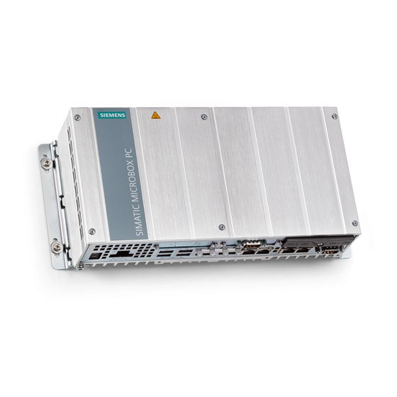
- Page 21 Interfaces 4.2 PC The device design corresponds to that of the SIMATIC IPC627D standard device supplemented by an additional cover with an RJ45 socket for the connection of the USB link cable. ① USB link interface Figure 4-2 IPC627D DMG interfaces NOTICE No LAN/WAN connection The RJ45 socket of the USB link interface is not an LAN/WAN connection and is only...
- Page 22 Interfaces 4.2 PC WARNING Internal front interfaces must not be used The following internal front interfaces on the SIMATIC IPC627D OEM motherboard must not be used: ● X570: Connection of LCD displays ● X571: Interface for I/O front ● X561: Internal USB 2.0 interface (USB channel 6) ●...
-
Page 23: Machine Control Panels
Interfaces 4.3 Machine control panels Machine control panels 4.3.1 Overview The position of the modules and interfaces is identical for both machine control panels. ① X302 USB-B (for connection of the CNC keyboard to the control panel) ② Slot for illuminated key (not in the scope of delivery) ③... - Page 24 Interfaces 4.3 Machine control panels X302 The X302 interface is designed as a "high powered interface" with max. 500 mA, 5 V. The connection between the keyboard and operator panel is established via X302. Connector designa‐ X302; USB-B connector, 4-pin tion: Table 4-1 Assignment of connector X302...
-
Page 25: Com Board Ie Mcp
Interfaces 4.3 Machine control panels 4.3.2 COM board IE MCP Overview The figure shows the position of the interfaces on the COM board of the machine control panels. 24 V power supply X20/X21 Ethernet ports Interface for feedrate override rotary switch Interface for rapid traverse override rotary switch X51/X52 Customer keys, inputs for illuminated keys... - Page 26 Interfaces 4.3 Machine control panels Bidirectional Power supply X10 power supply Connector designa‐ X10; 3-pin terminal block tion: Table 4-4 Assignment of connector X10 Signal name Signal type Meaning 24 V potential Ground 24 V SHIELD Shield connection Ethernet X20/X21 Connector designation: X20, X21 Connector type:...
- Page 27 Interfaces 4.3 Machine control panels Name Type Meaning Ground N.C. Not assigned 5 V supply OV_VS16 Override rotary switch, position/value 16 OV_VS8 Override rotary switch, position/value 8 OV_VS4 Override rotary switch, position/value 4 OV_VS2 Override rotary switch, position/value 2 OV_VS1 Override rotary switch, position/value 1 Rapid traverse override rotary switch X31 Connector designation:...
- Page 28 Interfaces 4.3 Machine control panels Figure 4-6 Schematic circuit diagram of the input circuit for X51 and X52 Interface: Optional customer keys IN Connector designation: X51 / X52 / X55 Connector type: 4-pin male connector Table 4-8 Assignment of connector X51 Name Type Meaning...
- Page 29 Interfaces 4.3 Machine control panels Optional customer keys X53/X54 The outputs X53 / X54 are intended to activate lamps in the keys. We would recommend using 1.2 W lamps with max. 0.3 A per output. High-side switches which switch 24 V to the lamps and limit the current during short circuits are used as output drivers.
- Page 30 Interfaces 4.3 Machine control panels Table 4-12 Assignment of connector X54 Name Type Meaning KT-OUT4 Customer key 4 lamp KT-OUT5 Customer key 5 lamp KT-OUT6 Customer key 6 lamp Ground Handwheels X60/X61 Interface: Handwheels Connector designation: X60/X61 Connector type: 15-pin Sub-D socket Table 4-13 Assignment of connector X60 Name...
- Page 31 Interfaces 4.3 Machine control panels Name Type Meaning N.C.- Not assigned P5HW 5V power supply N.C. Not assigned Ground N.C. Not assigned N.C. Not assigned N.C. Not assigned N.C. Not assigned Status LEDs Table 4-15 Meaning of the status LEDs Color Meaning Green...
- Page 32 Interfaces 4.3 Machine control panels Meaning MCP address 223 MCP address 222 MCP address 221 MCP address 220 MCP address 219 MCP address 218 MCP address 217 MCP address 216 MCP address 215 MCP address 214 MCP address 213 MCP address 212 MCP address 211 MCP address 210 MCP address 209...
-
Page 33: Input/Output Images
Interfaces 4.3 Machine control panels 4.3.3 Input/output images Input image for milling Byte Bit7 Bit6 Bit5 Bit4 Bit3 Bit2 Bit1 Bit0 IB 0 Cycle Spindle Spindle Spindle Single AUTO stop 100% block IB 1 Cycle Spindle Spindle Spindle DMG1 REPOS Teach start right... - Page 34 Interfaces 4.3 Machine control panels Byte Bit7 Bit6 Bit5 Bit4 Bit3 Bit2 Bit1 Bit0 IB 8 DT 8 DT 7 DT 6 DT 5 DT 4 DT 3 DT 2 DT 1 IB 9 DT 16 DT 15 DT 14 DT 13 DT 12 DT 11...
- Page 35 Interfaces 4.3 Machine control panels Figure 4-9 Turning key assignment Assignment of the inputs to the keys Figure 4-10 Keyboard layout Output image Byte Bit7 Bit6 Bit5 Bit4 Bit3 Bit2 Bit1 Bit0 QB 0 QB 1 QB 2 QB 3 QB 4 ERGOline Stage 3 Manual, 02/2015, 6FC5397-4FP40-0BA0...
-
Page 36: Circuit Diagrams
Interfaces 4.3 Machine control panels Byte Bit7 Bit6 Bit5 Bit4 Bit3 Bit2 Bit1 Bit0 QB 5 QB 6 QB 7 QB 8 QB 9 KT-OUT6 KT-OUT5 KT-OUT4 KT-OUT3 KT-OUT2 KT-OUT1 4.3.4 Circuit diagrams Handwheel (MCP 466C-T IE) Figure 4-11 Handwheel block diagram Note When a connected handwheel triggers pulses from its idle position or in the event of tiny contacts, connect it so that the label is facing the wrong way. - Page 37 Interfaces 4.3 Machine control panels Figure 4-12 Handwheel pulse diagram ERGOline Stage 3 Manual, 02/2015, 6FC5397-4FP40-0BA0...
- Page 38 Interfaces 4.3 Machine control panels ERGOline Stage 3 Manual, 02/2015, 6FC5397-4FP40-0BA0...
-
Page 39: Connection
Connection The following system configuration is suitable for the communication between the individual components: Figure 5-1 System configuration for ERGOline stage 3 ERGOline Stage 3 Manual, 02/2015, 6FC5397-4FP40-0BA0... - Page 40 Connection USB cables ● For the connection of: – CNC keyboard of the MCP (X302) to the monitor (X61/X62). – External USB devices, such as the mouse or keyboard, to the PC or the monitor. Max. cable length: 3 m ●...
-
Page 41: Operating
● Make sure that the touch screen is kept free of dirt. You can find information on cleaning on the Internet in the following article: What are the chemical resistances of the SIMATIC HMI operating devices and Industrial PCs? (https://support.industry.siemens.com/cs/ #document/39718396?lc=en-WW). Always check whether the executed operator actions were recognized by the device. - Page 42 Operating ERGOline Stage 3 Manual, 02/2015, 6FC5397-4FP40-0BA0...
-
Page 43: Technical Specifications
Technical specifications Monitor 7.1.1 Technical specifications Table 7-1 SIMATIC IFP2200 MT OEM Safety Degree of protection according to DIN EN 61140 Degree of protection according to DIN EN Front IP65 60529 Rear IP20 Approvals CE / UL Electrical data Input voltage 24 VDC Mechanical data Dimensions (WxHxD) -
Page 44: Operating Conditions
Technical specifications 7.1 Monitor The fault-free and safe operation of the device requires correct transport, storage, installation and assembly, as well as careful operation and maintenance. The warranty for the device is void if these regulations are not complied with. 7.1.3 Operating conditions Mechanical and climatic conditions of use... - Page 45 Technical specifications 7.1 Monitor Testing mechanical ambient conditions The table below provides information on the type and scope of tests for mechanical ambient conditions. Tested for Test standard Comments Vibration Vibration test according to Type of vibration: DIN EN 60068, part 2–6 (si‐ Frequency cycles at a rate of change of 1 octave/minute.
-
Page 46: Industrial Pc
Technical specifications 7.2 Industrial PC Industrial PC The technical specifications of the SIMATIC IPC627D standard device apply for the device. ERGOline Stage 3 Manual, 02/2015, 6FC5397-4FP40-0BA0... -
Page 47: Machine Control Panels
Technical specifications 7.3 Machine control panels Machine control panels Table 7-2 Machine control panels Safety Safety class III; PELV according to EN 50178 Degree of protection accord‐ Front side IP54 Rear side IP00 ing to DIN EN 60529 Approvals CE / UL Electrical data Input voltage 24 VDC... - Page 48 Technical specifications 7.3 Machine control panels ERGOline Stage 3 Manual, 02/2015, 6FC5397-4FP40-0BA0...
-
Page 49: Spare Parts
Spare parts Overview The table provides an overview of the spare parts available for the machine control panels. Name Description Quantity Order number Handwheel For turning machine control panel 6FC9320-5DM00 Feedrate / rapid tra‐ Electronic rotary switch 1x23G, T=32, cap, knob, pointer, rap‐ 6FC5247-0AF13-1AA0 verse override id traverse and feedrate dials... -
Page 50: Replacement
Spare parts 8.2 Replacement Replacement 8.2.1 Handwheel Removing the handwheel ① ⑥ 1. Loosen the grub screw of the rotary knob 2. Pull the rotary knob off the axle. ② 3. Loosen the fastening nut M15 4. Remove the washer. 5. -
Page 51: Rotary Switch
Spare parts 8.2 Replacement Connection Note When a connected handwheel triggers pulses from its idle position or in the event of tiny contacts, connect it so that the label is facing the wrong way. Exchange - The wire of terminal A with the wire of terminal /A - The wire of terminal B with the wire of terminal /B The pin assignments of the handwheel interfaces can be found in Section COM board IE MCP (Page 25). - Page 52 Spare parts 8.2 Replacement Installing the rotary switch ① 1. Push the O-ring onto the axle of the new rotary switch as a gasket. 2. Insert the rotary switch into the front cutout so that pressure is applied to the O-ring. ④...
- Page 53 Spare parts 8.2 Replacement Proceed in the same way to install the second rotary switch. NOTICE Damage to the components through incorrect installation of the rotary switches ● It is essential that the specified tightening torques are complied with. ● Make sure that the connection cable is cleanly folded as in the figure and lay it so that it does not come into contact with any chafing edges.
- Page 54 Spare parts 8.2 Replacement ERGOline Stage 3 Manual, 02/2015, 6FC5397-4FP40-0BA0...
-
Page 55: Accessories
Accessories The following accessories are available for the machine control panels: Component Description Quantity Order number For universal use 6XV1840-2AH10 Ethernet cables Trailable 6XV1840-3AH10 Ethernet connector 180° 6GK1901-1BB10-2AA0 ERGOline Stage 3 Manual, 02/2015, 6FC5397-4FP40-0BA0... - Page 56 Accessories ERGOline Stage 3 Manual, 02/2015, 6FC5397-4FP40-0BA0...
-
Page 57: Index
Index Ambient conditions Climatic, 45 Mechanical, 44 Test, 45 Test For ambient conditions, 45 Conditions, 44 With additional measures, 44 ERGOline Stage 3 Manual, 02/2015, 6FC5397-4FP40-0BA0... - Page 58 Index ERGOline Stage 3 Manual, 02/2015, 6FC5397-4FP40-0BA0...
Need help?
Do you have a question about the SINUMERIK 840D sl and is the answer not in the manual?
Questions and answers