Table of Contents
Advertisement
Quick Links
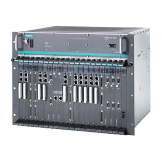
SIMATIC TDC hardware
SIMATIC TDC
SIMATIC TDC hardware
System Manual
12/2013
A5E01114865-07
___________________
Preface
General technical
___________________
specifications
___________________
Rack
___________________
CPU modules
___________________
Signal modules
___________________
Expansion modules
___________________
Communication modules
___________________
Interface module
___________________
Submodules
1
2
3
4
5
6
7
8
Advertisement
Table of Contents

Subscribe to Our Youtube Channel
Related Manuals for Siemens SIMATIC TDC


Summary of Contents for Siemens SIMATIC TDC
- Page 1 ___________________ SIMATIC TDC hardware Preface General technical ___________________ specifications ___________________ Rack SIMATIC TDC ___________________ CPU modules ___________________ SIMATIC TDC hardware Signal modules ___________________ Expansion modules System Manual ___________________ Communication modules ___________________ Interface module ___________________ Submodules 12/2013 A5E01114865-07...
- Page 2 Note the following: WARNING Siemens products may only be used for the applications described in the catalog and in the relevant technical documentation. If products and components from other manufacturers are used, these must be recommended or approved by Siemens. Proper transport, storage, installation, assembly, commissioning, operation and maintenance are required to ensure that the products operate safely and without any problems.
-
Page 3: Preface
This manual describes the principles in using the D7-SYS automation software and its functions, while setting the focus on the corresponding Technology and Drive Control components SIMATIC TDC, FM 458-1 DP, T400, SIMADYN D. TDC: Technology and Drive Control Basic knowledge required This manual addresses programmers and commissioning engineers. - Page 4 Just a few steps away from the first project communication configuring This chapter provides a very simple way of getting you started with the methodology for D7-SYS configuring and programming the SIMATIC TDC/SIMADYN D control system. It is particularly (http://support.automation. useful for newcomers to the system. siemens.com/WW/view/de...
- Page 5 This chapter describes the function blocks that can be configured in all target systems of SIMATIC D7-SYS. Chapter 2 This chapter describes the function blocks that can be configured only for SIMATIC TDC. Chapter 3 This chapter describes the function blocks that can be configured only for the FM 458-1 DP application module.
- Page 6 "Services". Note on IT security Siemens offers IT security mechanisms for its automation and drive product portfolio in order to support the safe operation of the plant/machine. We recommend that you inform yourself regularly on the IT security developments regarding your products. You can find information on this on the Internet (http://support.automation.siemens.com).
-
Page 7: Table Of Contents
EMC Directive ..........................15 1.1.5 Low-voltage directive ........................16 1.1.6 Machinery Directive ........................16 1.1.6.1 Overview ............................16 1.1.6.2 SIMATIC TDC outputs ......................... 16 1.1.6.3 Expert personnel .......................... 16 1.1.6.4 Input of external voltages ......................16 1.1.7 Installation ............................ 17 1.1.8 Repairs/maintenance ........................ - Page 8 Environmental conditions ......................36 1.3.1 Climatic conditions ........................36 1.3.2 Electrical protection and safety requirements ................37 1.3.3 External supply of the SIMATIC TDC modules (digital outputs) ..........37 1.3.4 Mechanical requirements ......................37 1.3.5 Electromagnetic requirements (industry) ..................37 Rack ..............................39 Rack UR5213 (6DD1682-0CH2) ....................
- Page 9 Status and fault displays ......................109 6.3.4 Application notes and immunity to interference ................. 110 6.3.5 Connection options ........................110 6.3.6 Additional components ....................... 111 6.3.7 Pin assignments ......................... 111 6.3.8 Technical specifications/performance features ................112 SIMATIC TDC hardware System Manual, 12/2013, A5E01114865-07...
- Page 10 Status and fault displays ......................151 6.8.4 Application notes and immunity to interference ................ 153 6.8.5 Connection options ........................154 6.8.6 Additional components ......................154 6.8.7 Pin assignments ........................155 6.8.8 Technical specifications/performance features ................. 155 SIMATIC TDC hardware System Manual, 12/2013, A5E01114865-07...
- Page 11 Function description ........................190 7.6.2 Additional components ....................... 191 7.6.3 Application notes ........................191 7.6.4 Pin/terminal assignment X1/X2 ....................192 7.6.5 Technical specifications ......................193 Submodules ............................195 Program memory modules ......................195 Index..............................197 SIMATIC TDC hardware System Manual, 12/2013, A5E01114865-07...
- Page 12 Table of contents SIMATIC TDC hardware System Manual, 12/2013, A5E01114865-07...
-
Page 13: General Technical Specifications
Furthermore, the contents of these Operating Instructions shall not become a part of or modify any prior or existing agreement, commitment, or legal relationship. All obligations on the part of Siemens AG are contained in the respective sales contract which also contains the complete and solely applicable warranty conditions. These contractual guarantee provisions are neither broadened nor restricted by the text in these operating instructions. -
Page 14: Danger And Warning Notes
This design and EMC Directive supplements the documentation on the individual components. The SIMATIC TDC control system consists of individual components (e.g. racks, modules, interface modules, operator control panels, position transmitters). The components can be installed in the widest range of system configurations to suit individual requirements. In an environment that contains distributed components it is imperative not to neglect interference and to conform with special installation and EMC requirements of the plant. -
Page 15: Ce Label
(control and drive system). Proper functioning of SIMATIC TDC can only be ensured if all of these measures have been observed in compliance with legal provisions (2004/108/EC). -
Page 16: Low-Voltage Directive
1.1.6.4 Input of external voltages An external voltage source (e.g. pulse encoder) that is connected to SIMATIC TDC module inputs must be shut down simultaneously with the shutdown or failure of the SIMATIC TDC power supply. SIMATIC TDC hardware System Manual, 12/2013, A5E01114865-07... -
Page 17: Installation
General technical specifications 1.1 Installation and EMC guidelines 1.1.7 Installation SIMATIC TDC components are considered open equipment (open equipment) that must be installed in metallic enclosures containing shielding and equipotential busbars in compliance with IEC 61010-1. 1.1.8 Repairs/maintenance Faulty modules must be returned to the manufacturer for repairs. Repairs must always be carried out by the manufacturer. -
Page 18: Fire Protection
As output power exceeds the limit of circuitry with power limiting to IEC61010-1, malfunction of a SIMATIC TDC component may pose the risk of fire (IEC61010-1). In order to prevent spreading of fire, suitable measures must be taken to prevent ignition of adjacent parts or components as a result of burning parts that possibly drop out of a component. - Page 19 General technical specifications 1.1 Installation and EMC guidelines ① Rack ② Vertical projection of the rack ③ from the vertical projection profile ④ Minimum size of the barrier SIMATIC TDC hardware System Manual, 12/2013, A5E01114865-07...
-
Page 20: Control Cabinet
● If contactors without protective circuit are operated in a control cabinet next to the SIMATIC TDC cabinet, the cabinets must be partitioned by means of a sheet steel panel. ● All control cabinets in which SIMATIC TDC components are operated must be equipped with a shielding busbar that must be connected directly at both ends to the cabinet frame. -
Page 21: Equipotential Bonding
16 mm 1.1.10.2 Principle of component connections All components (racks, power supplies, etc.) that are connected by signal cables must also be interconnected by means of equipotential bonding (exception: components with fiber-optic connections). SIMATIC TDC hardware System Manual, 12/2013, A5E01114865-07... -
Page 22: Equipotential Busbar
1.1 Installation and EMC guidelines 1.1.10.3 Equipotential busbar An equipotential busbar should be provided in each control cabinet to facilitate wiring. All internal and external components must be interconnected with this equipotential busbar. Schematic circuit diagram SIMATIC TDC hardware System Manual, 12/2013, A5E01114865-07... -
Page 23: Practical Application Examples
General technical specifications 1.1 Installation and EMC guidelines 1.1.10.4 Practical application examples Termination of an external shielded cable ● The shield must be bonded to the shielding busbar SIMATIC TDC hardware System Manual, 12/2013, A5E01114865-07... - Page 24 Termination of an external shielded cable with supply via interface module ● The shield must be bonded to the shielding busbar ● Ground of the external power supply must be wired to the shielding busbar, or to the equipotential busbar. SIMATIC TDC hardware System Manual, 12/2013, A5E01114865-07...
- Page 25 Termination of an internal power supply via interface module ● The shield must be bonded to the shielding busbar ● Ground of the internal power supply must be connected to the shielding busbar, or to the equipotential busbar. SIMATIC TDC hardware System Manual, 12/2013, A5E01114865-07...
- Page 26 General technical specifications 1.1 Installation and EMC guidelines Example of grounding and equipotential bonding SIMATIC TDC hardware System Manual, 12/2013, A5E01114865-07...
-
Page 27: Protective Ground
Protective ground Protective ground is bonded to the cabinets or components via PE conductor. The equipotential bonding does not provide a PE function in SIMATIC TDC. It is required in SIMATIC TDC for safe operation and as interference suppression measure. -
Page 28: Installation Variants
1.1.12.3 Air intake temperature The maximum air intake temperature on the SIMATIC TDC may not be exceeded. The following limits are valid, depending on the "shutdown mode" switch setting on the rack. Shutdown mode Maximum air intake temperature up to 2000 m above sea level 60°... -
Page 29: Power Supply
A) or overvoltage arrester in the mains line, as close as possible to the cable entry on the cabinet. Ground of the line filter/arrester must be wired to the equipotential busbar of the cabinet using the shortest possible conductor length. SIMATIC TDC hardware System Manual, 12/2013, A5E01114865-07... -
Page 30: Power Supply
SIMATIC TDC devices and modules. 1.1.13.4 Power supply potentials In SIMATIC TDC, the ground connections of all secondary voltages are grouped and bonded to the rack enclosure in order to improve the signal to interference ratio and to ensure proper grounding. -
Page 31: Rack
● All modules and front panels must be screwed onto the rack. This rule also applies to commissioning phase! ● Unused slots must be provided with SIMATIC TDC dummy front panels type SR 51 6DD 1682-0DA1. ● The connectors must be screwed/interlocked to the front panel. -
Page 32: Cables
● A minimum clearance of > 10 cm must be maintained between signal lines and power cables carrying voltages less than 500 V AC and > 30 cm to power cables carrying voltages of more than 1 kV AC. SIMATIC TDC hardware System Manual, 12/2013, A5E01114865-07... -
Page 33: Wiring Via Interface Module
If interface modules are used, the shields of system-side cables and of routed the interface module to SIMATIC TDC must be bonded to ground directly above or below the interface module. Unshielded conductors that are terminated to screw terminals should be kept as short as possible. -
Page 34: Connector X1 (Only For Ur5113 6Dd1682-0Ch2)
ESD Directives 1.2.1 What is ESD? Almost all of the SIMATIC TDC modules contain highly integrated components. Due to their technology, these components are highly sensitive to overvoltage and, therefore, to ESD. The abbreviation stands for electrostatic discharge Modules equipped with such components are identified by the following warning label on... -
Page 35: Handling Esd Modules
– after the probe used with an electrically isolated measuring device has been briefly discharged (e.g. by touching a bright metal part of the control enclosure). Always use ESD soldering irons for soldering work on modules, or at least grounded soldering tips. SIMATIC TDC hardware System Manual, 12/2013, A5E01114865-07... -
Page 36: Shipping Modules
1080 to 795 hPa (corresponds to -1000 m to +2000 m) Pollutant stress Gases posing the risk of malfunction Rated conditions to IEC 60721, Part 3-3; Class 3C3 Dust posing the risk of malfunction Rated conditions to IEC 60721, Part 3-3; Class 3S2 SIMATIC TDC hardware System Manual, 12/2013, A5E01114865-07... -
Page 37: Electrical Protection And Safety Requirements
EN 61000-6-2 : 2005 NOTICE Using two-way radios and mobile telephones The use of two-way radios and mobile phones in the immediate range of SIMATIC TDC can influence the operation of the device. SIMATIC TDC hardware System Manual, 12/2013, A5E01114865-07... - Page 38 General technical specifications 1.3 Environmental conditions SIMATIC TDC hardware System Manual, 12/2013, A5E01114865-07...
-
Page 39: Rack
2.1.1 Areas of application Rack UR5213 with 21 slots forms the mechanical base for SIMATIC TDC and features an integrated system power supply and integrated system fans. A high-performance 64-bit backplane bus supports high-speed data exchange between the inserted modules. -
Page 40: Control And Display Elements
You can restart all modules by pressing the submerged pushbutton (rack RESET). BATTERY Backup battery compartment (1 x AA lithium battery) Line voltage connection Front panel Switch S1 (viewed from the top of the fan tray) Figure 2-2 Front view of the fan tray SIMATIC TDC hardware System Manual, 12/2013, A5E01114865-07... -
Page 41: Status And Fault Displays
System was stopped SHUTDOWN Mode Shutdown on failure of two fans (corresponds to the OFF (yellow) position of switch S1.4) Flashing Shutdown on failure of one fan (corresponds to the ON position of switch S1.4) SIMATIC TDC hardware System Manual, 12/2013, A5E01114865-07... -
Page 42: Power Supply
16 A thermo magnetic circuit- breaker (B characteristic). Alternatively, a slow-acting fuse may be used. Note A mains disconnect unit must be provided during installation of the rack. SIMATIC TDC hardware System Manual, 12/2013, A5E01114865-07... -
Page 43: Wiring Diagram
The power supply unit and therefore the system are restarted automatically on recovery from a voltage dip below the permissible mains voltage. The power on/off sequence (e.g. generation of a RESET or SYSFAIL signal) corresponds to the reaction to manual operation of the mains switch. SIMATIC TDC hardware System Manual, 12/2013, A5E01114865-07... - Page 44 (bus signal *SYSFAIL=low): ● Modules can reset their digital and analog outputs ● CPU modules can go into the "STOP" state ("H" is displayed permanently) SIMATIC TDC hardware System Manual, 12/2013, A5E01114865-07...
-
Page 45: Battery Backup
(max. temperature 100° C), or recharge the battery - risk of explosion! Do not open the battery and always replace it with one of the same type. Always order replacements from Siemens. This ensures that you are in possession of a short circuit- proof type. -
Page 46: Modules
Observe this particularly at slot 1, as a metal spring has been installed in this slot. 2.1.10 Power supply potentials In SIMATIC TDC, the ground connections of all secondary voltages are grouped and bonded to the rack enclosure in order to improve the signal to interference ratio and to ensure proper grounding. -
Page 47: Ventilation/Cooling
35 °C. The power supply is not shut down on failure of a single fan, but the corresponding backplane bus signal (FANAL*) is activated and can be detected by the configuration software. SIMATIC TDC hardware System Manual, 12/2013, A5E01114865-07... -
Page 48: Technical Specifications
-40 °C to +70 °C Operating temperatures 0 °C to +60 °C Relative air humidity 5 % to 95 %, no condensation Atmospheric pressure Operation: 1080 hPa to 795 hPa Storage: 1080 hPa to 660 hPa SIMATIC TDC hardware System Manual, 12/2013, A5E01114865-07... - Page 49 Note If using other modules, you must check the individual maximum currents and verify the maximum load of 320 W. All outputs are sustained short circuit-proof and do not need a basic load. SIMATIC TDC hardware System Manual, 12/2013, A5E01114865-07...
- Page 50 Rated current Dimensions Number of rack slots Dimensions W x H x D [mm] approx. 482.6 x 354.9 x 343 Weight Approx. 20 kg Dimensional drawing Figure 2-3 Dimensional drawing of rack UR5213 SIMATIC TDC hardware System Manual, 12/2013, A5E01114865-07...
-
Page 51: Rack Ur5213 (6Dd1682-0Ch0)
2.2.1 Areas of application Rack UR5213 with 21 slots forms the mechanical base for SIMATIC TDC and features an integrated system power supply and integrated system fans. A high-performance 64-bit backplane bus supports high-speed data exchange between the inserted modules. -
Page 52: Control And Display Elements
You can restart all modules by pressing the submerged pushbutton (rack RESET). BATTERY Compartment for backup batteries (2 x 1.5 V leak-proof alkaline manganese cells type AA) POWER Mains switch Line voltage connection Front panel Figure 2-5 Front view of the power supply unit SIMATIC TDC hardware System Manual, 12/2013, A5E01114865-07... -
Page 53: Status And Fault Displays
Alternatively, a slow-acting fuse may be used. WARNING The PE/ground conductor must be connected to the power supply. A PE/ground terminal on the rack is inappropriate. The PE/ground conductor must be green with yellow stripe (green/yellow). SIMATIC TDC hardware System Manual, 12/2013, A5E01114865-07... -
Page 54: Voltage Monitoring
(bus signal *SYSFAIL=low): ● Modules can reset their digital and analog outputs ● CPU modules can go into the "STOP" state ("H" is displayed permanently) SIMATIC TDC hardware System Manual, 12/2013, A5E01114865-07... -
Page 55: Battery Backup
You should always replace the battery while the rack is powered on in order to prevent data loss. Note that while installing the battery you also need to take corresponding measures in preparation for its replacement. SIMATIC TDC hardware System Manual, 12/2013, A5E01114865-07... -
Page 56: Ventilation/Cooling
Table 2- 4 Signaling relay Signaling relay Terminal X1 Contact in switched off state Contact in error-free LED in error-free operation operation SYSFAIL Closed Closed POWER Open Closed green is on FAN FAIL Open Closed SIMATIC TDC hardware System Manual, 12/2013, A5E01114865-07... -
Page 57: Technical Specifications
15 ms Output voltages Rated output voltage Output current +5 V 60 A +3.3 V 60 A +12 V -12 V All outputs are sustained short circuit-proof and do not need a basic load. SIMATIC TDC hardware System Manual, 12/2013, A5E01114865-07... -
Page 58: Slot Covers
Slot covers Application Slot cover SR51 is used to protect unused slots of the rack. This is necessary to ensure proper ventilation and EMC compatibility of the system. Order number Slot cover SR51 6DD1682-0DA1 SIMATIC TDC hardware System Manual, 12/2013, A5E01114865-07... -
Page 59: Cpu Modules
The acknowledge button can be used to clear sporadic or non-critical fault displays on the 5x7 dot matrix LED. An additional fault is displayed after the first one has been acknowledged. ● Digital signal input can be evaluated using the ASI function block. SIMATIC TDC hardware System Manual, 12/2013, A5E01114865-07... - Page 60 CPU modules 3.1 CPU module CPU550/CPU551 Front panel Figure 3-1 Front panel of CPU551 SIMATIC TDC hardware System Manual, 12/2013, A5E01114865-07...
-
Page 61: Status And Fault Displays
For example, missing, low backup battery • Missing program memory module • Fan failure • Invalid floating value (substitute value will be used) • SIMATIC TDC hardware System Manual, 12/2013, A5E01114865-07... - Page 62 Flashing "H" Faults on this module • Permanent "H": Faults on a different module • For more information on diagnostics functions, refer to the "D7-SYS - STEP 7, CFC and SFC configuring” Manual, Section, Basic software, “Diagnostics” section. SIMATIC TDC hardware System Manual, 12/2013, A5E01114865-07...
-
Page 63: Application Notes And Immunity To Interference
For more information on fan operation, refer to chapter "Rack (Page 39)"! For more information on EMC and environmental conditions, refer to chapter "General technical specifications (Page 13)"! 3.1.5 Connection options Figure 3-2 Connection options of CPU550/CPU551 SIMATIC TDC hardware System Manual, 12/2013, A5E01114865-07... -
Page 64: Additional Components
DTR (Data Terminal Ready) n.c. n.c. GND (Ground) DSR (Data Set Ready) n.c. n.c. RTS (Request to Send) n.c. n.c. CTS (Clear to Send) n.c. n.c. RI (Ring Indicator) n.c. n.c. (n.c.) n.c. n.c.: n.c. SIMATIC TDC hardware System Manual, 12/2013, A5E01114865-07... -
Page 65: Technical Specifications/Performance Features
Where two different values are specified for a feature (separated by „/”) in the manual, the first is valid for the module with order number 6DD1600-0BA1 and the second for the module with order number 6DD1600-0BA2. Processor 64 bit RISC processor Clock frequency 266 / 500 MHz cycle SIMATIC TDC hardware System Manual, 12/2013, A5E01114865-07... - Page 66 Module slots Number Allocation of the slots Program memory MC5xx • Software protection • PMC plug-in cards • Equipped by the user. PMC plug-in cards are currently not provided. Time Resolution 0.1 ms SIMATIC TDC hardware System Manual, 12/2013, A5E01114865-07...
- Page 67 The module provides a socket for a hardware block for implementation of a software security function for the user program. This hardware block can be checked using a special function block. ● Additional information on request. SIMATIC TDC hardware System Manual, 12/2013, A5E01114865-07...
- Page 68 (independent of the protocol used) Voltage, currents Rated voltages at 25 °C Typical current consumption +5 V 1.5 A +3.3 V 2.0 A +12 V 40 mA -12 V 40 mA Backup battery 2.2 / 3 µA SIMATIC TDC hardware System Manual, 12/2013, A5E01114865-07...
- Page 69 3.1 CPU module CPU550/CPU551 Power losses/fan Typical power losses 15 W Fan required Dimensions Number of slots required in the rack Dimensions W x H x D [mm] 20 x 233 x 160 Weight 0.6 kg SIMATIC TDC hardware System Manual, 12/2013, A5E01114865-07...
- Page 70 CPU modules 3.1 CPU module CPU550/CPU551 SIMATIC TDC hardware System Manual, 12/2013, A5E01114865-07...
-
Page 71: Signal Modules
H1 (green) and H2 (red) Module status display H3 (green) and H4 (green) Can be controlled by means of function block BIQ8 (digital output). H5 (green) and H6 (green) H7 (green) and H8 (green) SIMATIC TDC hardware System Manual, 12/2013, A5E01114865-07... -
Page 72: Status And Fault Displays
Module status During voltage run-up FPGAs are configured, module is not initialized Module is initialized and operating error-free After 3.3 V voltage failure Hardware failure => Power-down the rack and replace the SM500 • SIMATIC TDC hardware System Manual, 12/2013, A5E01114865-07... -
Page 73: Application Notes And Immunity To Interference
For more information on fan operation, refer to chapter "Rack (Page 39)"! For more information on EMC and environmental conditions, refer to chapter "General technical specifications (Page 13)"! 4.1.5 Connection options Figure 4-2 Connection options of SM500 SIMATIC TDC hardware System Manual, 12/2013, A5E01114865-07... -
Page 74: Additional Components
15 V encoder, switching threshold 7 V ● Switch closed (ON): 5 V encoder, switching threshold 0 V All tracks (A/VW, B/RW, N/-) of a channel must have the same switch setting for operation. SIMATIC TDC hardware System Manual, 12/2013, A5E01114865-07... - Page 75 The Switches S1.7 / S1.8 and S2.7 / S2.8 are without function. Switches S1 and S2 for setting the threshold for incremental encoders (see encoder synchronization) Position of switches S1 and S2 on the module SIMATIC TDC hardware System Manual, 12/2013, A5E01114865-07...
-
Page 76: Pin Assignments
Integrating analog input 1- Integrating analog input 3 - Integrating analog input 2 + Integrating analog input 4 + Integrating analog input 2 - Integrating analog input 4 - Ground, analog input Ground, analog input SIMATIC TDC hardware System Manual, 12/2013, A5E01114865-07... - Page 77 Absolute encoder 3, data D- Absolute encoder 4, data D- Absolute encoder 3, clock C+ Absolute encoder 4, clock C+ Absolute encoder 3, clock C- Absolute encoder 4, clock C- Ground, encoder SSI Ground, encoder SSI SIMATIC TDC hardware System Manual, 12/2013, A5E01114865-07...
- Page 78 Absolute encoder 1, data D- Absolute encoder 2, data D- Absolute encoder 1, clock C+ Absolute encoder 2, clock C+ Absolute encoder 1, clock C- Absolute encoder 2, clock C- Ground, encoder SSI Ground, encoder SSI SIMATIC TDC hardware System Manual, 12/2013, A5E01114865-07...
- Page 79 Digital input 24 V • Digital input 48 V • Reference • SB70 Digital outputs (relay) Root (center contact) • NC contact • NO contact • SB71 Digital outputs (transistor) Signal • Ground • SIMATIC TDC hardware System Manual, 12/2013, A5E01114865-07...
- Page 80 4/54 41/42/44 4/54 Digital output 13 5/55 51/52/54 5/55 Digital output 14 6/56 61/62/64 6/56 Digital output 15 7/57 71/72/74 7/57 Digital output 16 8/58 81/82/84 8/58 Ext. power supply +24V External ground SIMATIC TDC hardware System Manual, 12/2013, A5E01114865-07...
- Page 81 3/13/53 Digital input 12 4/54 44/42/41 4/14/54 Digital input 13 5/55 54/52/51 5/15/55 Digital input 14 6/56 64/62/61 6/16/56 Digital input 15 7/57 74/72/71 7/17/57 Digital input 16 8/58 84/82/81 8/18/58 External ground SIMATIC TDC hardware System Manual, 12/2013, A5E01114865-07...
-
Page 82: Technical Specifications/Performance Features
± 0.3 % Gain error, max. • ± 24 LSB Offset error, max. • Slew rate approx. 3.5 V/µs Voltage output Yes (to ground) Short-circuit protection • Approx. 100 mA Short-circuit current • SIMATIC TDC hardware System Manual, 12/2013, A5E01114865-07... - Page 83 0.05 % Integral linearity error, max. Gain error, max. 2 LSB (software adjustment) Typical offset error Input resistance 470 kΩ Input filter 2 kHz Reverse polarity protection Yes, as differential inputs are used SIMATIC TDC hardware System Manual, 12/2013, A5E01114865-07...
- Page 84 • +13.5 V to +33 V For 1 signal • Input current 0 mA For 0 signal, normally • 3 mA For 1 signal, normally • Delay time per channel, max. 100 µs SIMATIC TDC hardware System Manual, 12/2013, A5E01114865-07...
- Page 85 0 V to 5 V Valid range • < 0.5 V 0 signal, max. • > 2.0 V 1 signal, min. • Input current -2.8 mA 0 signal, min. • -1.6 mA 1 signal, min. • SIMATIC TDC hardware System Manual, 12/2013, A5E01114865-07...
- Page 86 150 mA (short circuit-proof, short-circuit current approx. 250 mA) Voltage, currents Rated voltages at 25 °C Typical current consumption +5 V +3.3 V 50 mA +12 V 300 mA -12 V 300 mA SIMATIC TDC hardware System Manual, 12/2013, A5E01114865-07...
- Page 87 Power losses/fan Typical power losses 12.5 W Fan required Dimensions Number of slots required in the rack Dimensions W x H x D [mm] 20 x 233 x 160 Weight, approx. 0.7 kg SIMATIC TDC hardware System Manual, 12/2013, A5E01114865-07...
- Page 88 Signal modules 4.1 SM500 signal module SIMATIC TDC hardware System Manual, 12/2013, A5E01114865-07...
-
Page 89: Expansion Modules
Expansion modules Overview No expansion modules available SIMATIC TDC hardware System Manual, 12/2013, A5E01114865-07... - Page 90 Expansion modules 5.1 Overview SIMATIC TDC hardware System Manual, 12/2013, A5E01114865-07...
-
Page 91: Communication Modules
● Central commissioning of all CPU modules in the rack (MPI nodes) ● Buffer memory for data exchange between CPU modules ● Function for routing to other CP modules ● Connection of SIMATIC visualization components, e.g.: WinCC, or OP/TD SIMATIC TDC hardware System Manual, 12/2013, A5E01114865-07... -
Page 92: Control And Display Elements
LEDs H1, H2, H7 and H8 indicate the operating state of communication module CP50M1. LEDs H3 to H6 provide information about the current operating state of the two PROFIBUS DP channels. Front panel Figure 6-1 Front panel of CP50M1 SIMATIC TDC hardware System Manual, 12/2013, A5E01114865-07... -
Page 93: Status And Fault Displays
CP50M1, one or several slaves connected to the PB-DP1 interface are not responding H5 (green) CP50M1, PB-DP2 is initialized and ready H6 (red) CP50M1, PB-DP2 bus error Flashing CP50M1, one or several slaves connected to the PB-DP2 interface are not responding SIMATIC TDC hardware System Manual, 12/2013, A5E01114865-07... -
Page 94: Application Notes And Immunity To Interference
For more information on fan operation, refer to chapter "Rack (Page 39)"! For more information on EMC and environmental conditions, refer to chapter "General technical specifications (Page 13)"! 6.1.5 Connection options Figure 6-2 Connection options of CP50M1 SIMATIC TDC hardware System Manual, 12/2013, A5E01114865-07... -
Page 95: Additional Components
Bus cable for PROFIBUS 6XV1 830-0AH10 Bus connector 6ES7 972-0BA40-0XA0 Note For more information, refer to the SINEC Catalog IK10, SIMATIC S5/S7 Catalog, and to the "SIMATIC S5 distributed I/O system ET200" Manual SIMATIC TDC hardware System Manual, 12/2013, A5E01114865-07... -
Page 96: Pin Assignments
Ground P5, electrically isolated (to supply OLMs) 1/2P5EXT P5 electrically isolated (to OLM supply) (5 V DC/90 mA) PB1/2_P24MPI P24, non-isolated (24 V DC/150 mA) PB1/2_RS458_A Line A PB1/2_RTSPG RTS from programming device (n.c.) Enclosure Shield SIMATIC TDC hardware System Manual, 12/2013, A5E01114865-07... -
Page 97: Technical Specifications/Performance Features
• PG/OP services can be used E.g. coupling with the configuration station • • (CFC in test mode) Power supply to Optical Link Modules (OLM) with See Pin assignments (Page 96) electrical isolation SIMATIC TDC hardware System Manual, 12/2013, A5E01114865-07... -
Page 98: Cp50M0 Communication Module
● Interfacing with distributed I/O devices and/or drives (master and/or slave function) ● Central commissioning of all CPU modules in the rack (MPI nodes) ● Buffer memory for data exchange between CPU modules ● Connection of SIMATIC visualization components, e.g.: WinCC, or OP/TD SIMATIC TDC hardware System Manual, 12/2013, A5E01114865-07... -
Page 99: Control And Display Elements
H3 (green) and H4 (yellow) Display the status of PROFIBUS DP/MPI interface X1 H5 (green) and H6 (yellow) Display of the status of PROFIBUS DP/MPI interface X2 Front panel Figure 6-3 Front panel of CP50M0 SIMATIC TDC hardware System Manual, 12/2013, A5E01114865-07... -
Page 100: Status And Fault Displays
Check the configuration of @PRODP • Flashing at CFC and COM configuration inconsistent 0.5 Hz Bus operation is restricted • No bus operation (initialization phase), no data traffic via PROFIBUS DP interface X1 SIMATIC TDC hardware System Manual, 12/2013, A5E01114865-07... -
Page 101: Application Notes And Immunity To Interference
● The module may not be inserted or removed while the rack is on live voltage. Note For more information on fan operation, refer to chapter "Rack (Page 39)"! For more information on EMC and environmental conditions, refer to chapter "General technical specifications (Page 13)"! SIMATIC TDC hardware System Manual, 12/2013, A5E01114865-07... -
Page 102: Connection Options
Pin assignments for X1 and X2 RS 232 (Download) TxD = 2 RxD = 7 Ground = 1 RS 485 (PROFIBUS) +Tx/Rx = 3 -Tx/Rx = 8 M5EXT = 5 P5EXT = 6 Connection options of CP50M0 SIMATIC TDC hardware System Manual, 12/2013, A5E01114865-07... -
Page 103: Additional Components
Note For more information, refer to the SINEC Catalog IK10, SIMATIC S5/S7 Catalog, and to the "SIMATIC S5 distributed I/O system ET200" Manual Additional software Designation Order number COM PROFIBUS 6ES5 895-6SE12 (German) SIMATIC TDC hardware System Manual, 12/2013, A5E01114865-07... -
Page 104: Pin Assignments
Table 6- 10 Pin assignment of the cable (PC ↔ CP50M0) for the “SS52load” load program CP50M0 (X1 or X2) PC (9-pole connector) PC (25-pole connector) Designation Designation Designation Ground Ground Ground SIMATIC TDC hardware System Manual, 12/2013, A5E01114865-07... -
Page 105: Technical Specifications/Performance Features
Parameterizing and diagnostics interfaces RS 232 format Download of the bus configuration • Parameterization of the bus node • Power supply to Optical Link Modules (OLM) with See Pin assignments (Page 96) electrical isolation SIMATIC TDC hardware System Manual, 12/2013, A5E01114865-07... - Page 106 ● COM1/2 interface of the PC and RS-232 parameterizing/diagnostics interface by means of the "SS52load" driver program. COM PROFIBUS is available on separate order. Order no.: 6ES5 895-6SE12 (German) The "SS52load" driver program is included in COM PROFIBUS V3.1 or higher. SIMATIC TDC hardware System Manual, 12/2013, A5E01114865-07...
-
Page 107: Cp51M1 Communication Module
● Exchange of process data with third-party systems (e.g. process computers) ● Central commissioning and diagnostics of all CPU modules in the rack ● Buffer memory for data exchange between CPU modules ● Time synchronization for uniform system time SIMATIC TDC hardware System Manual, 12/2013, A5E01114865-07... -
Page 108: Control And Display Elements
LEDs H1, H2, H7 and H8 indicate the operating state of communication module CP51M1. LEDs H3 to H6 provide information about the current network traffic. Front panel Figure 6-4 Front panel of CP51M1 SIMATIC TDC hardware System Manual, 12/2013, A5E01114865-07... -
Page 109: Status And Fault Displays
Data traffic in transmit and/or receive direction on Ethernet H5 (green) CP51M1 is communicating via Fast Ethernet (100 Mbps) Flashing CP51M1 is in the "auto-sensing phase“ H6 (green) CP51M1 is connected (link) to an Ethernet compatible device (hub, switch, PC) SIMATIC TDC hardware System Manual, 12/2013, A5E01114865-07... -
Page 110: Application Notes And Immunity To Interference
For more information on fan operation, refer to chapter "Rack (Page 39)"! For more information on EMC and environmental conditions, refer to chapter "General technical specifications (Page 13)"! 6.3.5 Connection options Figure 6-5 Connection options of CP51M1 SIMATIC TDC hardware System Manual, 12/2013, A5E01114865-07... -
Page 111: Additional Components
SIMATIC Net, Industrial Ethernet TP XP CORD 6XV1870-3R... RJ45/RJ45, dressed with 2 x RJ45 connectors, length ... For information on additional products, refer to: https://mall.ad.siemens.com (https://mall.ad.siemens.com) For more information on networks and their cabling, refer to the following documentation: Designation... -
Page 112: Technical Specifications/Performance Features
Dielectric strength to IEEE 802.3 • Voltage, currents Rated voltages at 25 °C Typical current consumption +5 V DC (from rack) 1.044 A External battery (min. 2.2 V, typically 3.0 V) 350 nA SIMATIC TDC hardware System Manual, 12/2013, A5E01114865-07... -
Page 113: Cp5100 Communication Module
● Exchange of process data with other CP5100 and SIMATIC Industrial Ethernet modules (e.g. CP443-1) ● Visualization of process data in WinCC ● Visualization of messages in WinCC ● Exchange of process data with third-party systems (e.g. process computers) SIMATIC TDC hardware System Manual, 12/2013, A5E01114865-07... -
Page 114: Control And Display Elements
The RESET switch must be set to "RUN". Operation of the RESET switch triggers a communication error. The switch is only intended for test purposes and firmware updates by the manufacturer. Front panel Figure 6-6 Front panel of CP5100 SIMATIC TDC hardware System Manual, 12/2013, A5E01114865-07... -
Page 115: Status And Fault Displays
LED address decoder has detected a data packet for CP5100 (the LED is only briefly lit) H11 (yellow) 10/100 Mbit Ethernet connection available H12 (yellow) 100 Mbit Ethernet H13 (yellow) Data traffic on SIMATIC TDC hardware System Manual, 12/2013, A5E01114865-07... -
Page 116: Application Notes And Immunity To Interference
RESET. ● Serial interfaces X1 and X2 are required for diagnostics purposes and are not relevant for users. ● Connectors X4 and X5 are not available for use with SIMATIC TDC. SIMATIC TDC hardware System Manual, 12/2013, A5E01114865-07... -
Page 117: Connection Options
For more information on fan operation, refer to chapter "Rack (Page 39)"! For more information on EMC and environmental conditions, refer to chapter "General technical specifications (Page 13)"! 6.4.5 Connection options Figure 6-7 Connection options of CP5100 SIMATIC TDC hardware System Manual, 12/2013, A5E01114865-07... -
Page 118: Additional Components
SIMATIC Net, Industrial Ethernet TP CORD 6XV1850-2GE50 RJ45/RJ45, TP Cord dressed with 2 x RJ45 connectors, length 0.5 m For information on additional products, refer to: https://eb.automation.siemens.com (https://eb.automation.siemens.com) For more information on networks and their cabling, refer to the following documentation: Designation... -
Page 119: Pin Assignments
TxD (Transmit Data) n.c. GND (Ground) n.c. n.c. n.c. n.c. n.c.: n.c. Industrial Ethernet (10/100BT) interface X3 (RJ-45 jack) Table 6- 18 Pin assignment of X3 (RJ-45 jack) Designation TX - Shield Shield Shield Shield SIMATIC TDC hardware System Manual, 12/2013, A5E01114865-07... -
Page 120: Technical Specifications/Performance Features
For 10 Mbit or 100 Mbit networks Transmission modes • Can be set Autosensing • On request via the Hotline Default router • On request via the Hotline Thin-Wire Ethernet (Cheapernet) X4 Ethernet (MAU) X5 SIMATIC TDC hardware System Manual, 12/2013, A5E01114865-07... - Page 121 0.1 A Power losses/fan Power loss, max. 13 W Fan required Dimensions Number of slots required in the rack Dimensions W x H x D [mm] 20 x 233 x 160 Weight 0.6 kg SIMATIC TDC hardware System Manual, 12/2013, A5E01114865-07...
-
Page 122: Gdm Memory Module Cp52M0
Each rack that is coupled with GDM must be equipped with a CP52A0 access module. These racks are interconnected with GDM by means of fiber-optic cables in a star topology. Figure 6-8 Example of a GDM system with 5 racks that are coupled with FOCs SIMATIC TDC hardware System Manual, 12/2013, A5E01114865-07... - Page 123 CP52M0 reads the fault and diagnostics registers from all fiber-optic interfaces of the CP52IOs inserted in the GDM rack and detects and evaluates the central operating state of all fiber-optic interfaces. The results is made available at the digital outputs of CP52M0 for further analysis. SIMATIC TDC hardware System Manual, 12/2013, A5E01114865-07...
-
Page 124: Control And Display Elements
H3 (green) and H4 (red) Display of error states (see Status and fault displays (Page 109)) H5 (green) and H6 (red) H7 (green) and H8 (green) Front panel Figure 6-9 Front panel of CP52M0 SIMATIC TDC hardware System Manual, 12/2013, A5E01114865-07... -
Page 125: Status And Fault Displays
Logical status "1" => FOC interface is OK • Logical status "0" => Error at FOC interface, or CP52IO is missing • DA16 Logical status "1" => RUN operating state • Logical status "0" => STOP operating state • SIMATIC TDC hardware System Manual, 12/2013, A5E01114865-07... - Page 126 The data buffer is no longer released. The task start will be skipped. Software time monitoring • If the basic sampling time is not processed four times in succession. The basic clock cycle timer is re-initialized with the configured basic sampling time and processing continued. SIMATIC TDC hardware System Manual, 12/2013, A5E01114865-07...
-
Page 127: Application Notes And Immunity To Interference
Fan operation, EMC and environmental conditions • For more information on fan operation, refer to chapter "Rack (Page 39)". • For more information on EMC and environmental conditions, refer to chapter "General technical specifications (Page 13)". SIMATIC TDC hardware System Manual, 12/2013, A5E01114865-07... - Page 128 1. Install a suppressor diode between the shield and +24 . 2. Install a suppressor diode between the shield and M (ground). Figure 6-10 Circuit for the suppressor diodes on the lightning arrestor SIMATIC TDC hardware System Manual, 12/2013, A5E01114865-07...
-
Page 129: Connection Options
Order number: 918 402 DEHN + SÖHNE GmbH + Co KG Postfach 1640 92306 Neumarkt, Germany ● Suppressor diode Type: 1.5KE36CA (1500W) Manufacturer: e.g. STMicroelectronics, Vishay 6.5.5 Connection options Figure 6-11 Connection options of CP52M0 SIMATIC TDC hardware System Manual, 12/2013, A5E01114865-07... -
Page 130: Additional Components
DTR (Data Terminal Ready) n.c. n.c. GND (Ground) DSR (Data Set Ready) n.c. n.c. RTS (Request to Send) n.c. n.c. CTS (Clear to Send) n.c. n.c. RI (Ring Indicator) n.c. n.c. (n.c.) n.c. n.c.: not connected SIMATIC TDC hardware System Manual, 12/2013, A5E01114865-07... - Page 131 Digital output 14 n.c. Digital output 15 n.c. Digital output 16 n.c. Ext. power supply +24V n.c. External ground External ground n.c. n.c. n.c. n.c. n.c. n.c. n.c. n.c. n.c. n.c. n.c.: not connected SIMATIC TDC hardware System Manual, 12/2013, A5E01114865-07...
-
Page 132: Technical Specifications/Performance Features
Ground • External power supply • Short-circuit current, max. 250 mA Total current of outputs (up to 60 °C) 16 x 50 mA Limiting of inductive cut-off voltages Ext. supply voltage +1 V SIMATIC TDC hardware System Manual, 12/2013, A5E01114865-07... - Page 133 Power losses/fan Typical power losses 4.5 W Fan required Dimensions Number of slots required in the rack Dimensions W x H x D [mm] 20 x 233 x 160 Weight, approx. 0.6 kg SIMATIC TDC hardware System Manual, 12/2013, A5E01114865-07...
-
Page 134: Cp52Io Gdm Interface Module
Each rack that is coupled with GDM must be equipped with a CP52A0 access module. These racks are interconnected with GDM by means of fiber-optic cables in a star topology. Figure 6-12 Example of a GDM system with 5 racks that are coupled with FOCs SIMATIC TDC hardware System Manual, 12/2013, A5E01114865-07... -
Page 135: Control And Display Elements
FOC interface 2 receives data H5 (green) FOC interface 3 transmits data H6 (yellow) FOC interface 3 receives data H7 (green) FOC interface 4 transmits data H8 (yellow) FOC interface 4 receives data SIMATIC TDC hardware System Manual, 12/2013, A5E01114865-07... - Page 136 Communication modules 6.6 CP52IO GDM interface module Front panel Figure 6-13 Front panel of CP52IO SIMATIC TDC hardware System Manual, 12/2013, A5E01114865-07...
-
Page 137: Status And Fault Displays
● The module may not be inserted or removed while the rack is on live voltage. Note • For more information on fan operation, refer to chapter "Rack (Page 39)"! • For more information on EMC and environmental conditions, refer to chapter "General technical specifications (Page 13)"! SIMATIC TDC hardware System Manual, 12/2013, A5E01114865-07... -
Page 138: Connection Options
The max. cable length for the connection between CP52IO and CP52A0 is 200 m. The fiber-optic cables must be assembled in accordance with the plant topology and can be ordered from the following supplier: Ehret GmbH Über der Elz 2 79312 Emmerdingen, Germany SIMATIC TDC hardware System Manual, 12/2013, A5E01114865-07... -
Page 139: Pin Assignments
0.8 A Power losses/fan Typical power losses 18 W Fan required Dimensions Number of slots required in the rack Dimensions W x H x D [mm] 20 x 233 x 160 Weight 0.6 kg SIMATIC TDC hardware System Manual, 12/2013, A5E01114865-07... -
Page 140: Cp52A0 Gdm Access Module
Each rack that is coupled with GDM must contain a CP52A0 access module. These racks are interconnected with GDM by means of fiber-optic cables in a star topology. Figure 6-15 Example of a GDM system with 5 racks that are coupled with FOCs SIMATIC TDC hardware System Manual, 12/2013, A5E01114865-07... -
Page 141: Control And Display Elements
FOC interface is transmitting data H4 (yellow) FOC interface is receiving error-free data H5 (green) Startup ID H6 (yellow) Send authorization for clock triggers or base sampling time Front panel Figure 6-16 Front panel of CP52A0 SIMATIC TDC hardware System Manual, 12/2013, A5E01114865-07... -
Page 142: Status And Fault Displays
The clock trigger and basic sampling time have been parameterized for transmission but have no transmit authorization from the CP52IO (priority logic is inhibiting one of the two signals) The brightness of the LED indicates the density of periodic data traffic. SIMATIC TDC hardware System Manual, 12/2013, A5E01114865-07... -
Page 143: Application Notes And Immunity To Interference
● The module may not be inserted or removed while the rack is on live voltage. Note • For more information on fan operation, refer to chapter "Rack (Page 39)"! • For more information on EMC and environmental conditions, refer to chapter "General technical specifications (Page 13)"! SIMATIC TDC hardware System Manual, 12/2013, A5E01114865-07... -
Page 144: Connection Options
The max. cable length for the connection between CP52IO and CP52A0 is 200 m. The fiber-optic cables must be assembled in accordance with the plant topology and can be ordered from the following supplier: Ehret GmbH Über der Elz 2 79312 Emmerdingen, Germany SIMATIC TDC hardware System Manual, 12/2013, A5E01114865-07... -
Page 145: Pin Assignments
3.3 V 0.4 A Power losses/fan Typical power losses Fan required Dimensions Number of slots required in the rack Dimensions W x H x D [mm] 20 x 233 x 160 Weight 0.6 kg SIMATIC TDC hardware System Manual, 12/2013, A5E01114865-07... -
Page 146: Cp53M0 Coupling Module
Areas of application Rack coupling Coupling module CP53M0 is used to couple a SIMATIC TDC system to a SIMADYN D system for high-speed data exchange, e.g. when expanding SIMADYN D systems. CP53M0 is equipped with a buffer memory for data exchange between the CPU modules in the rack. - Page 147 The listing in the "Pin assignments of CP53M0 an SIMADYN D modules CS13 and CS14" table above also applies to the second ICS1 on CS14. If less than four slave modules are connected to an ICS1, the fiber-optic cables can be inserted as required in pairs. SIMATIC TDC hardware System Manual, 12/2013, A5E01114865-07...
-
Page 148: Cp53M0 As Master
One CS22 is connected to each of the FOC connectors X1/X2 or X3/X4 in a SIMADYN D rack. Figure 6-19 Options for connecting the CS22 to CP53M0 that is operating in master mode Table 6- 32 Pin assignment of two CS22 on a CP53M0 CP53M0 CS22(1) CS22(2) SIMATIC TDC hardware System Manual, 12/2013, A5E01114865-07... - Page 149 Example 2 Coupling SIMATIC TDC racks CP53M0 can be used to couple up to three SIMATIC TDC racks. In this case, CP53M0 is parameterized for operation in master mode in one rack and in slave mode in the other two racks.
-
Page 150: Control And Display Elements
Data transmission to X1/X2 H5 (green) Status startup frame to X3/X4 H6 (yellow) Data transmission to X3/X4 H7 (green) Status fiber-optic cable link to X1/X2 H8 (green) Status fiber-optic cable link to X3/X4 SIMATIC TDC hardware System Manual, 12/2013, A5E01114865-07... -
Page 151: Status And Fault Displays
FPGAs are configured, module is not initialized Module is initialized and operating error-free After 3.3, 2.5 V or 1.2 V voltage failure Hardware failure => Switch off the rack and replace the CP53M0 • SIMATIC TDC hardware System Manual, 12/2013, A5E01114865-07... - Page 152 Receiver FOC interface X3/X4 has no valid receive signal Slave mode: No function Master mode: Receiver FOC interface X3/X4 has valid receive signal Slave mode: No function The brightness of the LED indicates the intensity of periodic data traffic. SIMATIC TDC hardware System Manual, 12/2013, A5E01114865-07...
-
Page 153: Application Notes And Immunity To Interference
Note See also: • For more information on fan operation, refer to chapter "Rack (Page 39)"! • For more information on EMC and environmental conditions, refer to chapter "General technical specifications (Page 13)"! SIMATIC TDC hardware System Manual, 12/2013, A5E01114865-07... -
Page 154: Connection Options
SIMATIC NET, STANDARD FIBER-OPTIC CABLE, SPLITTABLE, DRESSED WITH 4 x BFOC CONNECTORS Article number: 6XV1820-5Bxyz (xyz: length code) For information on available lengths, refer to the interactive catalog in the A&D MALL. The max. cable length is 200 m. SIMATIC TDC hardware System Manual, 12/2013, A5E01114865-07... -
Page 155: Pin Assignments
If several CPxxMx are used in a rack, only the CPxxMx on the extreme left has the buffer memory function. Interface FOC interface 2 (master mode) Number • 1 (slave mode) 96 Mbaud Data transmission speed • 5B/6B Code • SIMATIC TDC hardware System Manual, 12/2013, A5E01114865-07... - Page 156 0.5 A Power losses/fan Typical power losses 3.1 W Fan required Dimensions Number of slots required in the rack Dimensions W x H x D [mm] 20 x 233 x 160 Weight 0.6 kg SIMATIC TDC hardware System Manual, 12/2013, A5E01114865-07...
-
Page 157: Interface Module
6DD1681-0AE2 Description The interface module transfers digital signals from SIMATIC TDC components to the system, or receives digital signals from the system and transfers these to SIMATIC TDC components. The connection to SIMATIC TDC components is realized via the cables SC62 or SC66 and via terminals on system side. - Page 158 Interface module 7.1 Interface module SB10 Green LED The voltage supply on SIMATIC TDC side is indicated by a green LED (P). Red LED The supply voltage on SIMATIC TDC side (1P, 1M) is short-circuited (fault). Test socket Voltages 1P and 1M can be used via the double test socket (G; +) to simulate an input signal for SIMATIC TDC.
-
Page 159: Signals
The reference points of the signals may be derived from 1M or 1P potential. The polarity is selected on the module by means of soldering bridge: Figure 7-1 Soldering bridge for setting the signal reference points Note Bridge 1M-1W is inserted in the factory SIMATIC TDC hardware System Manual, 12/2013, A5E01114865-07... -
Page 160: Application Notes
Figure 7-2 Application example of an SB10 interface module on the digital I/O module SM500 The digital signals on system side are connected directly to the SIMATIC TDC modules via the interface module. A cable SC62 is used accordingly. SIMATIC TDC hardware... -
Page 161: Technical Specifications
The maximum current of 1 A may not be exceeded on connector X3 if the supply of several terminal blocks is routed via this connector. Digital signals Number Rated voltage 24 V DC Maximum current per channel 30 mA SIMATIC TDC hardware System Manual, 12/2013, A5E01114865-07... -
Page 162: Pin Assignment
7.1 Interface module SB10 7.1.4 Pin assignment Ribbon cable connector X1 The cables SC62 or SC66 are used to connect the interface modules to the SIMATIC TDC components (for more information, refer to the SIMATIC TDC Documentation). Terminal block X2 Table 7- 1... -
Page 163: Block Diagram
The eight digital inputs and the SIMATIC TDC rack are electrically separated. The eight digital inputs are electrically isolated with respect to one another. The cables SC62 or SC66 are used to connect the interface modules to the SIMATIC TDC components (for more information, refer to the SIMATIC TDC Documentation). - Page 164 – 1P and 1M for the voltage on SIMATIC side ● LED displays for diagnostics ● Optocoupler for electrical isolation between inputs and outputs Voltage supply on SIMATIC side The SIMATIC TDC voltage supply is fed to terminal X3: Terminal X3 Voltage on SIMATIC TDC side +24 V Connect the cables using accessory kit SM11 "Power supply connector for interface...
-
Page 165: Signals
Signals up to a maximum of 120 V (nominal value) DC or AC can be connected at the SB60 interface module. Yellow LED The status of the binary interface module outputs (binary inputs for SIMATIC TDC) is indicated using yellow LEDs (1...8). Terminal block X2 provides two screw terminals for each signal: ●... -
Page 166: Technical Specifications
0 V to 33 V Input current (‘1signal’) Max. 3 mA Dielectric strength Safety isolation guaranteed: - between inputs and outputs Electrical isolation guaranteed: - between input circuits Test voltage 1125 V AC or open-circuit input SIMATIC TDC hardware System Manual, 12/2013, A5E01114865-07... -
Page 167: Pin Assignment
7.2.4 Pin assignment Flat connector X1 The cables SC62 or SC66 are used to connect the interface modules to the SIMATIC TDC components (for more information, refer to the SIMATIC TDC Documentation). Digital inputs terminal block X2 Table 7- 2... -
Page 168: Block Diagram
Interface module SB61 is used to adapt 8 digital input signals with electrical isolation to the signal level of SIMATIC TDC components. The cables SC62 or SC66 are used to connect the interface modules to the SIMATIC TDC components (for more information, refer to the SIMATIC TDC Documentation). - Page 169 – 8 terminals for 48 V digital inputs – 8 terminals for reference potentials ● 1 terminal pair X3: 1P, 1M (voltage supply on SIMATIC TDC side) ● 1 terminal pair X4: 2P, 2M (voltage supply on plant side) ● Pin header for short-circuit plugs ●...
-
Page 170: Signals
There are three screw connections on terminal strip X2 for each signal: ● terminals 1 to 8 for 24 V binary signals ● terminals 11 to 18 for 48 V binary signals ● Terminals 51 to 58 for reference potential SIMATIC TDC hardware System Manual, 12/2013, A5E01114865-07... -
Page 171: Application Notes
Inputs, electrically isolated Figure 7-5 Position of the jumpers for electrically isolated inputs Inputs with common reference potential Figure 7-6 Position of the jumpers for inputs with common reference potential SIMATIC TDC hardware System Manual, 12/2013, A5E01114865-07... - Page 172 = number of input 1 to 8 Note The potential reference can be set separately for each input. The interface module is designed only for vertical mounting positions due to thermal losses to be dissipated. SIMATIC TDC hardware System Manual, 12/2013, A5E01114865-07...
-
Page 173: Technical Specifications
Mounting system The enclosure is suitable for snap-on mounting to rails Dimensions W x H x D [mm] 45 x 129 x 160 mm Weight Approx. 0.32 kg Ambient temperatures Ambient temperatures max. 60°°C SIMATIC TDC hardware System Manual, 12/2013, A5E01114865-07... - Page 174 13 V DC to 30 V DC 26 V DC to 60 V DC '0 signal' -3 V to +6 V -3 V to +12 V Input current (‘1signal’) 6 mA 6 mA or open-circuit input SIMATIC TDC hardware System Manual, 12/2013, A5E01114865-07...
-
Page 175: Pin Assignment
7.3 Interface module SB61 7.3.4 Pin assignment Flat connector X1 Use cable SC62 and SC66 to connect the interface module to the SIMATIC TDC components (for further information, refer to the documentation for the SIMATIC TDC components). Digital inputs, terminal block X2... -
Page 176: Block Diagram
6DD1681-0AG2 Description Interface module SB70 is used to adapt eight digital output signals from SIMATIC TDC to the signal level of the plant by means of relay circuits. The voltage of the output signal may amount up to max. 120 V DC or AC. - Page 177 – 8 terminals for the NO contact – 8 terminals for the NC contact – 8 terminals for the center contact ● 1 terminal pair X3: 1P, 1M (voltage on SIMATIC TDC side) ● Double test socket X5: 1P(+), 1M(G) ● LED displays for diagnostics ●...
-
Page 178: Signals
Red LED The supply voltage on SIMATIC TDC side (1P, 1M) is short-circuited (fault). Test socket The SIMATIC TDC supply voltage is available on the double test socket X5 (G; +): Double test socket X5 Voltage SIMATIC side + (1P of X3) -
Page 179: Application Notes
The following figure shows a typical application: Figure 7-9 Application example of an SB70 interface module on digital I/O module SM500 The digital inputs of the interface module are connected via cable SC62 to the SIMATIC TDC outputs. SIMATIC TDC hardware... -
Page 180: Technical Specifications
60 V DC < 35 V DC Switching frequency Max. 20 Hz Dielectric strength Safety isolation guaranteed: - between inputs and outputs Electrical isolation guaranteed: - between input circuits Test voltage 1125 V AC SIMATIC TDC hardware System Manual, 12/2013, A5E01114865-07... -
Page 181: Pin Assignment
7.4 Interface module SB70 7.4.4 Pin assignment Flat connector X1 Use the SC62 cable to connect the interface module to the SIMATIC TDC components (for more information, refer to the SIMATIC TDC documentation). Digital inputs, terminal block X2 Table 7- 5... -
Page 182: Block Diagram
6DD1681-0DH1 Description Interface module SB71 is used to adapt eight digital DC signals from SIMATIC TDC to the signal level on plant side in an electrically isolated circuit. Cable SC62 is used to connect the interface module to the SIMATIC TDC components (for further information, refer to the documentation for the SIMATIC TDC components). - Page 183 – 8 terminals for digital outputs, 24/48 V DC – 8 terminals for reference potentials ● 1 terminal pair X3: 1P and 1M (voltage supply on SIMATIC TDC side) ● 1 terminal pair X4: 2P, 2M (voltage supply on plant side) ●...
-
Page 184: Signals
(MLFB: 6DD1680-0BB0) The maximum conductor cross-section at terminal X4 is 2.5 mm². Test socket The SIMATIC TDC supply voltage is available on the double test socket X5 (G; +): Double test socket X5 Voltage SIMATIC side + (1P of X3) -
Page 185: Application Notes
Application notes The interface module is equipped with a ribbon cable connector X1 that is used to connect the output signals of the SIMATIC TDC system, as well as a terminal block X2 for wiring the plant signals. The interface module is designed only for vertical mounting positions due to thermal losses to be dissipated. -
Page 186: Technical Specifications
-2.0 V) at 30 mA output current -2.7 V) -2.9 V) Output voltage for '0 signal' Max. output current (for '1 signal') 30 mA 30 mA The digital outputs are sustained short circuit-proof. SIMATIC TDC hardware System Manual, 12/2013, A5E01114865-07... -
Page 187: Pin Assignment
7.5.4 Pin assignment Flat connector X1 Cable SC62 is used to connect the interface module to the SIMATIC TDC components (for further information, refer to the documentation for the SIMATIC TDC components). Digital outputs, terminal strip X2 Table 7- 6... -
Page 188: Block Diagram
Interface module 7.5 Interface module SB71 7.5.5 Block diagram Figure 7-12 Block diagram of interface module SB71 SIMATIC TDC hardware System Manual, 12/2013, A5E01114865-07... -
Page 189: Interface Modules Su12 Und Su13
16 spring-loaded terminals (X2) 10 spring-loaded terminals for analog or digital signals on plant side 6 unused spring-loaded terminals 10-pole connectors X1. SU13 50 screw terminals (X2) Connection of 50 signals 50-pole connector X1. SIMATIC TDC hardware System Manual, 12/2013, A5E01114865-07... -
Page 190: Function Description
Function description Interface modules SU12 and SU13 are used to wire a ribbon cable connector X1 on SIMATIC TDC side 1:1 to the terminal blocks X2 on plant side, with the exception of the following terminals. The following signal lines are fused at the terminals (0.5 A slow-blow, internal resistance 0.25 Ω):... -
Page 191: Additional Components
The interface modules are suitable for vertical and horizontal mounting positions. The modules must be installed on mounting rails. Other information For more information on EMC and environmental conditions, refer to section "General technical specifications (Page 13)" SIMATIC TDC hardware System Manual, 12/2013, A5E01114865-07... -
Page 192: Pin/Terminal Assignment X1/X2
X2 on terminal block X2 SU12 0.2 mm² 2.5 mm². SU13 0.2 mm² 1.5 mm². SU12 Figure 7-13 SU12 circuit diagram The components are described in chapter Function description (Page 190). SIMATIC TDC hardware System Manual, 12/2013, A5E01114865-07... -
Page 193: Technical Specifications
The components are described in chapter Function description (Page 190). 7.6.5 Technical specifications General data Dimensions W x H x D [mm] 45 x 129 x 160 mm Weight Approx. 0.28 kg Ambient temperatures Ambient temperatures max. 60°°C SIMATIC TDC hardware System Manual, 12/2013, A5E01114865-07... - Page 194 Interface module 7.6 Interface modules SU12 und SU13 SIMATIC TDC hardware System Manual, 12/2013, A5E01114865-07...
-
Page 195: Submodules
The volume of configuration data to download to the memory module (compressed to approx. 50 %) and the free program memory space can be viewed in the CFC by selecting: PLC / Load / Info SIMATIC TDC hardware System Manual, 12/2013, A5E01114865-07... - Page 196 8 KB 8 KB 8 KB Flash memory is non-volatile and can be electrically programmed and erased. Dimensions Dimensions W x H x D [mm] 54 x 85.6 x 3.3 mm Weight 30 g SIMATIC TDC hardware System Manual, 12/2013, A5E01114865-07...
-
Page 197: Index
Application notes and immunity to interference, 143 Control and display elements, 141 GlobalDataMemory CP52A0 Pin assignments, 145 CP52A0 GDM access module, areas of application Status and fault displays, 142 for CP52A0, 140 GlobalDataMemory CP52IO Technical specifications/performance features, 145 CP52IO SIMATIC TDC hardware System Manual, 12/2013, A5E01114865-07... - Page 198 Technical specifications, 48, 57 SM500 Technical specifications, 48, 57 Additional components, 74 Voltage monitoring, 43, 54 Voltage monitoring, 43, 54 Application notes and immunity to interference, 73 Areas of application of signal module SM500, 71 SIMATIC TDC hardware System Manual, 12/2013, A5E01114865-07...
- Page 199 Index Wiring via interface module, 33 SIMATIC TDC hardware System Manual, 12/2013, A5E01114865-07...
- Page 200 Index SIMATIC TDC hardware System Manual, 12/2013, A5E01114865-07...
Need help?
Do you have a question about the SIMATIC TDC and is the answer not in the manual?
Questions and answers