Siemens Sirius 3RK3 System Manual
Modular safety system industrial switchgear monitoring and control devices
Hide thumbs
Also See for Sirius 3RK3:
- Equipment manual (402 pages) ,
- Original operating instructions (21 pages) ,
- Operating instruction (3 pages)
Table of Contents
Advertisement
Quick Links
Advertisement
Table of Contents

Related Manuals for Siemens Sirius 3RK3


Summary of Contents for Siemens Sirius 3RK3
- Page 1 3RK3 Modular Safety System System Manual · 10/2009 Safety Integrated...
- Page 3 About this manual Product-specific information Overview SIRIUS industrial switchgear Getting Started Monitoring and control devices Modular Safety System 3RK3 Description of the hardware Description of the software System Manual Operator control Diagnostics / service Technical data Dimension drawings Evaluation/Feedback Certificates 10/2009 926 2530-02 DS 02...
- Page 4 Note the following: WARNING Siemens products may only be used for the applications described in the catalog and in the relevant technical documentation. If products and components from other manufacturers are used, these must be recommended or approved by Siemens. Proper transport, storage, installation, assembly, commissioning, operation and maintenance are required to ensure that the products operate safely and without any problems.
-
Page 5: Table Of Contents
Table of contents About this manual ............................ 11 Purpose of this manual ........................11 Required basic knowledge......................11 Topics dealt with ..........................11 Validity range ..........................12 Additional documentation......................12 Definitions ............................12 Correction sheet...........................12 User responsibility for system design and function..............13 Product-specific information........................15 General safety notes........................15 Safety information for hazardous areas..................16 Guidelines for inductive loads ......................16 Intended use ..........................18... - Page 6 Table of contents 5.1.5 Expansion module 2/4F-DI 1/2F-RO................... 47 5.1.6 Expansion module 2/4F-DI 2F-DO....................49 5.1.7 Expansion module 4F-DO......................51 5.1.8 Expansion module 4/8F-RO......................53 5.1.9 Expansion module 8DI ........................ 55 5.1.10 Expansion module 8DO ......................56 5.1.11 DP interface module........................58 5.1.12 Diagnostics module........................
- Page 7 Table of contents 6.4.1.8 Close ............................101 6.4.1.9 Information about the print options ....................101 6.4.1.10 Page setup..........................102 6.4.1.11 Print preview..........................104 6.4.1.12 Print............................104 6.4.1.13 List of the files last used......................105 6.4.1.14 Exit .............................105 6.4.2 Edit menu ...........................106 6.4.2.1 Undo............................106 6.4.2.2 Redo............................106 6.4.2.3 Cut..............................106...
- Page 8 Table of contents 6.4.4.10 Minimize / restore online dialogs....................119 6.4.5 Options menu..........................120 6.4.5.1 Basic settings..........................120 6.4.5.2 Modular Safety System ES settings - "General" tab ..............121 6.4.5.3 Settings of Modular Safety System ES - "Download settings" tab..........121 6.4.5.4 Settings of Modular Safety System ES - "Logic"...
- Page 9 Table of contents 6.7.2.2 Output cell ..........................164 6.7.3 Monitoring functions........................165 6.7.3.1 EMERGENCY STOP .........................165 6.7.3.2 ESPE (electro-sensitive protective equipment) .................167 6.7.3.3 Safety shutdown mat (NC principle) ..................169 6.7.3.4 Safety shutdown mat (cross-circuit principle) ................170 6.7.3.5 Protective door ...........................172 6.7.3.6 Enabling button ..........................174 6.7.3.7 Two-hand operation ........................175 6.7.3.8...
- Page 10 Table of contents 7.4.2 Cross references........................223 7.4.3 Symbol list ..........................224 Integrating the Modular Safety System 3RK3 in DP master systems ........225 7.5.1 Setting and changing the DP address ..................225 7.5.2 DP interface ..........................226 7.5.2.1 DP interface menu navigation ....................227 7.5.2.2 Menu mode with user control ....................
- Page 11 Table of contents 8.5.5 Data set 92..........................278 Restoring factory settings ......................284 Module replacement ........................286 Technical data ............................289 General technical data .......................289 Central unit..........................290 EM 4/8F-DI..........................291 EM 2/4F-DI 1/2F-RO........................292 EM 2/4F-DI 2F-DO........................293 EM 4F-DO ..........................294 EM 4/8F-RO ..........................295 EM 8DI ............................296 EM 8DO .............................297 9.10 MSS DP interface module......................298...
- Page 12 Table of contents Modular Safety System 3RK3 System Manual, 10/2009, 926 2530-02 DS 02...
-
Page 13: About This Manual
About this manual Purpose of this manual This manual contains a detailed description of the Modular Safety System (in short: MSS) 3RK3 and its components. This manual provides you with the information you require for configuring, commissioning and using the MSS. A typical safety application will provide you with a clear and practice-oriented introduction to the system. -
Page 14: Validity Range
3ZS1314-5CC10-0YA5 x = 1: Version with screw-type terminals: x = 2: Version with spring-loaded terminals: SIEMENS reserves the right of including a Product Information for each new component, and for each component of a later version. Additional documentation If you use products other than those described in this manual, you also require further documentation. -
Page 15: User Responsibility For System Design And Function
Nor can Siemens assume liability for recommendations that appear or are implied in the following description. No new guarantee, warranty, or liability claims beyond the scope of the Siemens general terms of supply are to be derived or inferred from the following description. Modular Safety System 3RK3... - Page 16 About this manual 1.8 User responsibility for system design and function Modular Safety System 3RK3 System Manual, 10/2009, 926 2530-02 DS 02...
-
Page 17: Product-Specific Information
Product-specific information General safety notes Note Safety category 4 in accordance with DIN EN 954-1 / SIL 3 in accordance with IEC 61508 / PL e in accordance with EN ISO 13849-1:2006 The Modular Safety System 3RK3 has been designed in such a way that applications can be implemented up to category 4 in accordance with EN 954-1/SIL 3 in accordance with IEC 61508/PL e in accordance with EN ISO 13849-1:2006. -
Page 18: Safety Information For Hazardous Areas
Product-specific information 2.2 Safety information for hazardous areas NOTICE Operational faults and malfunctions in communication If the EMC Directive 89/336/EEC (CE) is not observed when plants and devices are installed, communication breaks may occur. Note Cover all unused system interfaces. Safety information for hazardous areas WARNING Hazardous Voltage. - Page 19 Product-specific information 2.3 Guidelines for inductive loads DC outputs and relays that control DC loads The DC outputs are equipped with an internal protection system that is suitable for most applications. Since the relay can be used for a DC or AC load, an internal protection system is not provided.
-
Page 20: Intended Use
Proper use of hardware products This equipment is only allowed to be used for the applications described in the catalog and in the technical description, and only in conjunction with non-Siemens equipment and components recommended by Siemens. Correct transport, storage, installation and assembly, as well as careful operation and maintenance, are required to ensure that the product operates safely and without faults. -
Page 21: Current Information About Operational Safety
By subscribing to the appropriate newsletter, you will ensure that you are always up-to-date and able to make changes to your system, when necessary: SIEMENS newsletter http://www.automation.siemens.com/WW/newsletter/guiThemes2Select.aspx?subjectID=1 You can subscribe to the following newsletters by checking the appropriate boxes: •... - Page 22 Product-specific information 2.5 Current information about operational safety Modular Safety System 3RK3 System Manual, 10/2009, 926 2530-02 DS 02...
-
Page 23: Overview
Overview Introduction The Modular Safety System (MSS) 3RK3 is a modular safety relay. Depending on the version of the external wiring, applications can be implemented up to Category 4 in accordance with EN 954-1 or SIL3 in accordance with IEC 61508 / PL e in accordance with DIN EN ISO 13849-1:2006. -
Page 24: A Typical System Configuration
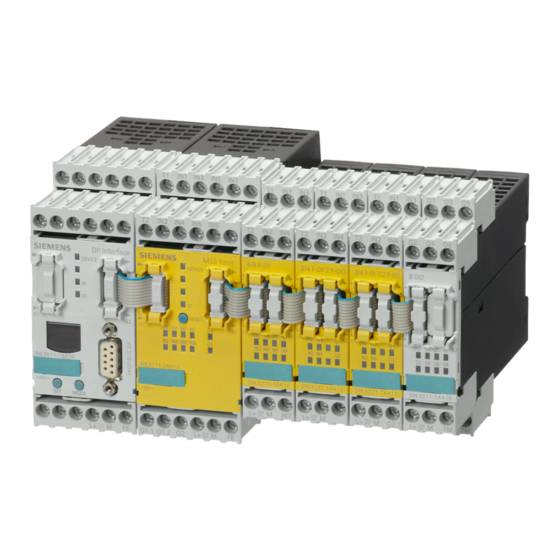
3.2 A typical system configuration A typical system configuration The schematic diagram below shows a typical MSS configuration. The system comprises a central unit, expansion modules, an interface module and a diagnostics module. SIRIUS 3RK3 DEVICE Diagnostics module Interface module Central unit (4) ... -
Page 25: System Components
Overview 3.3 System components System components Central unit For every system configuration you require a central unit (e.g. 3RK3 Basic). For executing the safety functions, the central unit contains the parameterization data in a plug-in memory module. The expansion modules and/or an interface module or the diagnostics module are connected to the central unit. - Page 26 Overview 3.3 System components Diagnostics module With the diagnostics module, you can check and analyze the diagnostics and status data of the MSS and acknowledge errors on site or from a central location. The diagnostics module has the following properties: ●...
- Page 27 Overview 3.3 System components Accessories The following components of the SIRIUS device family are available to you as accessories: Component Description Diagram Ribbon cable for data connection of system Connection cables • components via the system interfaces Mechanically-coded and color-coded protection •...
- Page 28 Overview 3.3 System components Modular Safety System 3RK3 System Manual, 10/2009, 926 2530-02 DS 02...
-
Page 29: Getting Started
Getting Started Introduction This section provides a step-by-step guide to commissioning a Modular Safety System 3RK3 (MSS) using an example demonstrating how to protect a metalworking press. The essential steps for commissioning the MSS are as follows: 1. Installation 2. Wiring 3. -
Page 30: Task And Structure Of The Example
Getting Started 4.3 Task and structure of the example Task and structure of the example Protecting a metalworking press ● The hazardous area is protected by permanent isolating protective equipment. ● The insertion point is additionally protected by electrosensitive protective equipment (ESPE). - Page 31 Getting Started 4.3 Task and structure of the example Figure 4-1 Typical system configuration Meaning Start pushbutton Two-hand operator panel EMERGENCY STOP control device Light curtain (ESPE) Modular Safety System 3RK3 System Manual, 10/2008, 926 2530-02 DS 02...
-
Page 32: Installing The Mss
Getting Started 4.4 Installing the MSS Installing the MSS Assembly/Installation Step Activity Hang the device on the mounting rail or screw it onto a level surface using the fixing lugs. Establish a connection between the central unit (interface X2) and the expansion module (interface X1) by means of a connection cable (0.025 m). -
Page 33: Wiring The Mss
Getting Started 4.5 Wiring the MSS Wiring the MSS Wiring NOTICE All components, including the light curtain, must be operated on the same power supply. Step Action Result Connect the central unit to the power The central unit is supplied with power. supply with: + 24 V to terminal L+ •... - Page 34 Getting Started 4.5 Wiring the MSS Step Action Result Connect the light curtain to the central unit of the MSS (terminal IN1/IN2) with Output 1 of the light curtain: Terminal • Output 2 of the light curtain: Terminal • Note: Please refer here to the operating instructions for the light curtain.
- Page 35 Getting Started 4.5 Wiring the MSS Step Action Result Connect the contactors QA and QB on the expansion module 2/4 F-DI 2F-DO of the MSS with: Contactor / coil QA: Terminal Q1 • Contactor / coil QB: Terminal Q2 • Connect the feedback circuit of the contactors QA and QB on the expansion module 2/4 F-DI 2F-DO of the MSS with:...
-
Page 36: Configuring The Mss
Getting Started 4.6 Configuring the MSS Configuring the MSS Configuration Step Activity Result Switch on your PC/PG. Install the MSS ES The MSS ES software is installed on your computer. software. Administrator rights are required here. Additional information: Description of the software (Page 87) Start the MSS ES software and choose The MSS ES software opens. - Page 37 Getting Started 4.6 Configuring the MSS Step Activity Result Drag the expansion module 2/4 F-DI 2F-DO from the catalog window to the next empty row (under the central unit added in the previous step) in the work space for the hardware configuration.
-
Page 38: Creating The Safety Program
Getting Started 4.7 Creating the safety program Creating the safety program Configuration Step Activity Result Drag the "ESPE" element from the • "Monitoring functions" folder to the work space. Open the "Properties - ESPE" dialog box • by double-clicking the block. Select the following in the "Parameter >... - Page 39 Getting Started 4.7 Creating the safety program Step Activity Result Drag the "Input cell" element from the "Cell • functions" folder to the work space. This cell function is required for acknowledging the EMERGENCY STOP control device. Open the "Properties - Input cell" dialog •...
- Page 40 Getting Started 4.7 Creating the safety program Step Activity Result Drag the "Input cell" element from the "Cell • functions" folder to the work space. This cell function is required for monitoring the feedback circuit. Open the "Properties - Input cell" dialog •...
-
Page 41: Mss Function Test
Getting Started 4.8 MSS function test MSS function test Download to 3RK3 Basic central unit Step Action Result Switch on the power supply. The safety relay executes a self-test. Choose "Edit" > "Check consistency". If no message is displayed in the output window, the test was successful. - Page 42 Getting Started 4.8 MSS function test Configuration release Step Action Result Select the menu command "Target system" > "Go The offline configuration is opened. offline". Choose "Target system" > "Approve configuration". The "Approve configuration" dialog box is opened, thereby confirming that the configuration test has been performed properly.
-
Page 43: Description Of The Hardware
Description of the hardware Description of the individual modules 5.1.1 General information on central units Figure 5-1 3RK3 Basic central unit Application The application area for MSS central units is safety-related control functions. A central unit is required for each system configuration. The central unit contains the configuring data in an external memory module, and it handles all control tasks. -
Page 44: 3Rk3 Basic Central Unit
Description of the hardware 5.1 Description of the individual modules If a valid configuration has been released, the DEVICE LED flashes green until the system switches to safety mode. 5.1.2 3RK3 Basic central unit Properties The 3RK3 Basic central unit is the basic component of the MSS for safety-related control functions. - Page 45 Description of the hardware 5.1 Description of the individual modules Structure of the 3RK3 Basic central unit Front view Meaning Removable terminal block D Removable terminal block C Connection to expansion module RESET button Removable terminal block A Connection of memory module Inscription label Display LEDs Connection of PC / PG / communications...
- Page 46 Description of the hardware 5.1 Description of the individual modules Interfaces of the 3RK3 Basic central unit Interface Meaning Description System interface Connection of PC / PG, interface module Interface Interface for connecting expansion modules (e.g. I/O modules) External memory module Slot for external memory module with parameterization data Operator controls on the 3RK3 Basic central unit...
-
Page 47: General Information On Expansion Modules
Description of the hardware 5.1 Description of the individual modules 5.1.3 General information on expansion modules Figure 5-2 Expansion modules of the MSS Application The expansion modules provide additional inputs and outputs for a central unit. Expansion modules always have to be connected to a central unit. Power-up/self-test Once the power supply has been applied, all the devices perform a self-test. - Page 48 Description of the hardware 5.1 Description of the individual modules Inputs and outputs The expansion module 4/8F-DI has the following inputs and outputs: ● 8 safety-related, parameterizable sensor inputs Design of the expansion module 4/8F-DI: Front view Meaning Removable terminal block D Removable terminal block C Interface X2 Inscription label...
-
Page 49: Expansion Module 2/4F-Di 1/2F-Ro
Description of the hardware 5.1 Description of the individual modules Displays of the expansion module 4/8F-DI Element Meaning SF / IN1 Group error / sensor input IN2 ... IN8 Sensor inputs Connecting inputs and outputs You can find more information on connecting inputs and outputs in the section Connecting safety-related inputs and outputs (Page 69). - Page 50 Description of the hardware 5.1 Description of the individual modules Design of the expansion module 2/4F-DI 1/2F-RO Front view Meaning Removable terminal block D Removable terminal block C Interface X2 Inscription label Removable terminal block A Removable terminal block B Display LEDs Interface X1 Terminal designations of the expansion module 2/4F-DI 1/2F-RO...
-
Page 51: Expansion Module 2/4F-Di 2F-Do
Description of the hardware 5.1 Description of the individual modules Displays of the expansion module 2/4F-DI 1/2F-RO Element Meaning SF / IN1 Group error / sensor input IN2, IN3, IN4 Sensor inputs Q1, Q2 Relay outputs Connecting inputs and outputs You can find more information on connecting inputs and outputs in the section Connecting safety-related inputs and outputs (Page 69). - Page 52 Description of the hardware 5.1 Description of the individual modules Design of the expansion module 2/4F-DI 2F-DO Front view Meaning Removable terminal block D Removable terminal block C Interface X2 Inscription label Removable terminal block A Removable terminal block B Display LEDs Interface X1 Terminal designations of the expansion module 2/4F-DI 2F-DO...
-
Page 53: Expansion Module 4F-Do
Description of the hardware 5.1 Description of the individual modules Displays of the expansion module 2/4F-DI 2F-DO Element Meaning SF / IN1 Group error / sensor input IN2, IN3, IN4 Sensor inputs Q1, Q2 Solid-state outputs Connecting inputs and outputs You can find more information on connecting inputs and outputs in the section Connecting safety-related inputs and outputs (Page 69). - Page 54 Description of the hardware 5.1 Description of the individual modules Structure of the expansion module 4F-DO Front view Meaning Removable terminal block D Removable terminal block C Interface X2 Inscription label Removable terminal block A Removable terminal block B Display LEDs Interface X1 Terminal designations of the expansion module 4F-DO Terminal...
-
Page 55: Expansion Module 4/8F-Ro
Description of the hardware 5.1 Description of the individual modules Connecting inputs and outputs You can find more information on connecting inputs and outputs in the section Connecting safety-related inputs and outputs (Page 69). 5.1.8 Expansion module 4/8F-RO Properties The expansion module 4/8F-RO supplements a central unit. To achieve SIL 3 or Pl e, 2 relay outputs must be interconnected in combination. - Page 56 Description of the hardware 5.1 Description of the individual modules Terminal designations of the 4/8F-RO expansion module Terminal Meaning Description Q1.1, Q1.2 Safety-related relay output Isolated output for connecting actuators Q2.1, Q2.2 Safety-related relay output Q3.1, Q3.2 Safety-related relay output Q4.1, Q4.2 Safety-related relay output Q5.1, Q5.2...
-
Page 57: Expansion Module 8Di
Description of the hardware 5.1 Description of the individual modules 5.1.9 Expansion module 8DI Properties The 8DI expansion module supplements a central unit. ● It is suitable as an input module with non-safety-related sensor inputs, e.g. for: – Displaying process statuses for operational switching. –... -
Page 58: Expansion Module 8Do
Description of the hardware 5.1 Description of the individual modules Interfaces of the expansion module 8-DI Interface Meaning Description Interface Connection of central unit/expansion module Interface Connection of expansion module Displays of the expansion module 8-DI Element Meaning SF / IN1 Group error / sensor input IN2 ... - Page 59 Description of the hardware 5.1 Description of the individual modules Design of the expansion module 8DO Front view Meaning Removable terminal block D Removable terminal block C Interface X2 Inscription label Removable terminal block A Removable terminal block B Display LEDs Interface X1 Terminal designations of the expansion module 8DO Terminal...
-
Page 60: Dp Interface Module
Description of the hardware 5.1 Description of the individual modules 5.1.11 DP interface module Figure 5-3 DP interface module Application Interface modules are the interface between the MSS and a higher-level bus system, e.g. PROFIBUS DP. The MSS uses them to make diagnostics and status information available to a higher-level controller. - Page 61 Description of the hardware 5.1 Description of the individual modules Properties The DP interface module has the following properties: ● The DP interface connects the MSS to PROFIBUS DP and thus with a higher-level programmable controller. ● The DP interface is integrated into the PLC via a GSD file. ●...
- Page 62 Description of the hardware 5.1 Description of the individual modules Interfaces of the DP interface module Interface Meaning Description System interface Connection of PC / PG, diagnostics module System interface Connection of central unit PROFIBUS DP 9-pin sub D socket Connection to PROFIBUS DP Operator controls and displays of the DP interface module Element...
-
Page 63: Diagnostics Module
Description of the hardware 5.1 Description of the individual modules 5.1.12 Diagnostics module Application A diagnostics module is available for the MSS that displays the current messages, diagnostics data and status information of the monitored system directly on the control cabinet such that an elementary diagnosis is possible without PC and MSS ES. - Page 64 5.1 Description of the individual modules Design of the diagnostics module Front view Meaning Front view: System interface X1 Display Arrow keys SIRIUS 3RK3 Park position for interface DEVICE cover Keys for menu navigation Display LED Functional ground System interface X2...
- Page 65 Description of the hardware 5.1 Description of the individual modules Displays Element Meaning DEVICE Status Bus error Group error Modular Safety System 3RK3 System Manual, 10/2008, 926 2530-02 DS 02...
-
Page 66: Mounting/Installing/Attaching
Description of the hardware 5.2 Mounting/installing/attaching Mounting/installing/attaching 5.2.1 Mounting the central unit, expansion module, or interface module on a DIN rail Requirements ● At the installation location, a horizontal 35 mm mounting rail in accordance with DIN EN 60715 is properly secured ●... -
Page 67: Installing The Diagnostics Module In A Control Cabinet Door/Switchboard
Description of the hardware 5.2 Mounting/installing/attaching ● Two screws with a maximum thread diameter of 4.8 mm ● Two plastic securing brackets Please refer to the accessories list for the relevant order numer in section System components (Page 23) Procedure for mounting on a level surface Step Operating instruction Figure... -
Page 68: Removing The Central Unit, Expansion Module, Or Interface Module
Description of the hardware 5.2 Mounting/installing/attaching NOTICE Degree of protection IP54 The degree of protection IP54 on the front is only guaranteed if: • The device has been properly installed with the supplied fixing elements • The system interface on the front has been protected with a system interface cover Procedure for installing in a control cabinet door / control panel Step Operating instruction... - Page 69 Description of the hardware 5.2 Mounting/installing/attaching Removing the central unit, expansion module, or interface module from a DIN rail Step Operating instruction Figure Pull the device down until the lower half can be pulled away from the DIN rail. Pull the lower half of the device away from the DIN rail.
-
Page 70: Removing The Diagnostics Module
Description of the hardware 5.2 Mounting/installing/attaching 5.2.5 Removing the diagnostics module Removing the diagnostics module from a control cabinet door/control panel Step Operating instruction Figure Take appropriate measures to ensure the diagnostics module does not fall out of the control cabinet door/control panel. -
Page 71: Connecting/Wiring
Description of the hardware 5.3 Connecting/wiring Connecting/wiring 5.3.1 Connecting safety-related inputs and outputs Inputs To achieve the required performance level or SIL, you can have single-channel or two- channel interconnection of the inputs of the MSS. The following connection methods are possible: ●... - Page 72 Description of the hardware 5.3 Connecting/wiring Connection methods of the safety-related inputs without cross-circuit detection 1 x single-channel sensor 1 x two-channel sensor IN1, IN2 Sensor inputs Relay outputs Safety-related outputs of the central unit are configured with 2 channels, those of the expansion modules with 1 channel.
- Page 73 Description of the hardware 5.3 Connecting/wiring QA, QB Contactors Qx.1, Qx.2 Safety-related relay outputs Note When inductive loads are controlled via a relay output, the load must be equipped with inductive interference protection. Solid-state outputs Internally, safety-related solid-state outputs always have a two-channel structure. As a result, each of these outputs can be used for applications up to PL e or SIL 3.
-
Page 74: Connecting Non-Safety-Related Inputs And Outputs
Description of the hardware 5.3 Connecting/wiring 5.3.2 Connecting non-safety-related inputs and outputs Connection methods of the non-safety-related inputs 1 x single-channel sensor Sensor input Connection methods of the non-safety-related solid-state outputs Single-channel actuator shutdown QA, QB Contactors Q1, Q2 Safety-related solid-state outputs 5.3.3 Guidelines for wiring the MSS WARNING... - Page 75 Description of the hardware 5.3 Connecting/wiring WARNING Hazardous Voltage. Can Cause Death, Serious Injury, or Property Damage. If a two-channel evaluation is carried out via a module comprising two single-channel function elements, the input signals must each be read by a linear and non-linear sensor input.
-
Page 76: Connection Data For Terminal Blocks
Description of the hardware 5.3 Connecting/wiring 5.3.4 Connection data for terminal blocks The following connection data apply dependent on the removable terminal block: Specification and value Specification and value in the case of removable in the case of removable terminal blocks with screw-type terminal blocks with spring- terminals loaded terminals... - Page 77 Description of the hardware 5.3 Connecting/wiring Requirements ● The insulation on the connection cables must be properly stripped to a length of 10 mm. ● Flexible cables must be fitted with end sleeves or cable lugs for connection to screw-type terminal blocks.
-
Page 78: Connecting The System Interfaces
Description of the hardware 5.3 Connecting/wiring 5.3.6 Connecting the system interfaces CAUTION EMC measures Unused system interfaces must be closed using system interface covers. CAUTION Off-circuit installation Connect the system interfaces only in a voltage-free state! If you connect system interfaces while the system is connected to the power supply, this can damage the safety components which, in turn, means that the safety function is no longer available. -
Page 79: Connecting A Diagnostics Module
Description of the hardware 5.3 Connecting/wiring Procedure for connecting the system interfaces Step Operating instruction Figure Insert the cable connector into the connector slot. Lock the locking element (1). Note the color coding (2) and mechanical coding. Pull on the connection cable to ensure the locking element has engaged. - Page 80 Only the central unit or the interface module may be connected to the system interface S2 ② on the rear of the diagnostics module. ● Connections on the front. SIRIUS 3RK3 DEVICE The front is normally accessible if the diagnostics module is installed. Components are only directly inserted in the system interface S1 ③...
-
Page 81: Establishing A Profibus Dp Connection
Description of the hardware 5.3 Connecting/wiring 5.3.8 Establishing a PROFIBUS DP connection PI installation guidelines In the case of electric PROFIBUS networks, note also the PROFIBUS DP/FMS installation guidelines defined by the PROFIBUS user organization. These contain important information about installing cables and commissioning PROFIBUS networks. Publisher: PROFIBUS-Nutzerorganisation e. -
Page 82: Disconnecting
Description of the hardware 5.3 Connecting/wiring 5.3.9 Disconnecting WARNING Hazardous Voltage. Can Cause Death, Serious Injury, or Property Damage. Before starting work, therefore, disconnect the system and devices from the power supply. Disconnecting PROFIBUS DP connection (if applicable) Step Operating instruction Figure Loosen the screws of the PROFIBUS DP connector. - Page 83 Description of the hardware 5.3 Connecting/wiring Removing terminal blocks from the device NOTICE Order of removal Remove terminal block A before terminal block B, and C before D. Step Operating instruction Figure Insert a flat-head screwdriver between the clip of the terminal block and the front panel (1). Pull the terminal block out to the front (2).
- Page 84 Description of the hardware 5.3 Connecting/wiring Disconnecting spring-loaded terminals Step Operating instruction Figure Insert the flat-head screwdriver into the square opening of the spring-loaded terminal until it engages. Please observe a 10° horizontal 3 mm angular deviation of the screwdriver to the oval opening.
-
Page 85: Plugging In Terminal Blocks
Description of the hardware 5.3 Connecting/wiring 5.3.10 Plugging in terminal blocks WARNING Hazardous Voltage. Can Cause Death, Serious Injury, or Property Damage. Before starting work, therefore, disconnect the system and devices from the power supply. Requirement You must have removed the terminal blocks, for the purpose of replacing a device, for example. -
Page 86: Connecting The Memory Module
Description of the hardware 5.3 Connecting/wiring 5.3.11 Connecting the memory module The memory module is included in the scope of delivery of the central unit. Program the memory module in the central unit that is connected to a configuring PC / PG. Connecting the memory module NOTICE The memory module must only be connected/disconnected when the central unit is... -
Page 87: Grounding
Description of the hardware 5.3 Connecting/wiring 5.3.12 Grounding WARNING Hazardous Voltage. Can Cause Death, Serious Injury, or Property Damage. Before grounding or wiring an electrical device, you must ensure that the power supply for the device is switched off. Ensure that all the connected devices are also switched off. Grounding via the FE terminal All electrical devices must be grounded and wired properly not only to ensure that your system functions as smoothly as possible but also to provide additional noise immunity for... - Page 88 Description of the hardware 5.3 Connecting/wiring Modular Safety System 3RK3 System Manual, 10/2009, 926 2530-02 DS 02...
-
Page 89: Description Of The Software
Description of the software Introduction 6.1.1 Overview The engineering system (ES) SIRIUS ES is the shared software platform for different communication-enabled switching devices. The Modular Safety System ES 2008 (MSS ES) engineering system is the software for configuring and parameterizing the Modular Safety System (MSS) 3RK3. It provides the following functions: ●... -
Page 90: License-Dependant Available Menu Commands
Description of the software 6.1 Introduction ● Standard (order number: 3ZS1 314-5CC10-0YA5) ● Basic (new) (order number: 3ZS1 314-4CC10-0YA5) (see "License-dependant available menu commands (Page 88)") The following are included on the CD ROM: Software Application MSS ES Configuring the MSS Adobe Reader Generation of printout and print preview, thus meeting the requirement for releasing the configuration;... - Page 91 Description of the software 6.1 Introduction License-dependent range of functions The following table lists the menu commands activated with the different licenses: Menu option Usable in Basic Usable in Standard Switching device New... Open... Import... Open Online... Save Save as... Export...
- Page 92 Description of the software 6.1 Introduction Menu option Usable in Basic Usable in Standard Load to PC... Go Offline Import from switching device Prepare configuration test... Approve configuration... Cancel configuration release Configuring mode Test mode Safety mode Commands... Diagnostics configuration Diagnostics logic View Toolbar...
-
Page 93: Requirements
Description of the software 6.1 Introduction 6.1.3 Requirements To be able to work with MSS ES, you must meet the following requirements: Software requirements The readme file (Readme.rtf) contains the current software requirements. ● You need administrator rights to install MSS ES. Main user rights are the minimum requirement for working with MSS ES under MS Windows 2000/XP/ VISTA. -
Page 94: Installation And Program Start
The Automation License Manager is available: ● On the product CDs of MSS ES ● As a download on the Internet pages for A&D Customer Support at Siemens AG. The Automation License Manager features an online help function that you can use to call up context-specific information via the F1 key, or via "Help"... -
Page 95: Installing The Automation License Manager
Description of the software 6.2 Installation and program start 6.2.1.2 Installing the Automation License Manager Installing Automation License Manager Automation License Manager is installed by a setup program. You will find the installation software for the Automation License Manager on the MSS ES product CD. You can install the Automation License Manager together with MSS ES or at a later point in time. -
Page 96: Rules For Using License Keys
Description of the software 6.2 Installation and program start 6.2.1.3 Rules for using license keys Additional information You can open the context-sensitive online help for the Automation License Manager by pressing F1 or by selecting the menu command "Help" > "Help on Automation License Manager". -
Page 97: Starting The Program
Description of the software 6.2 Installation and program start Step Description Open the main directory on the CD ROM. Double click on the "setup.exe" file to start the setup program. The setup program guides you step by step through the entire process of installing MSS 6.2.3 Starting the program Starting the MSS ES program on the PC... -
Page 98: User Interface
Description of the software 6.3 User interface User interface 6.3.1 Design of the user interface If you start the software of the 3RK3 (MSS ES) Modular Safety System and create a new project using the menu command "Switching device" > "New", then the user interface opens in the "Configuration"... -
Page 99: Toolbar
Description of the software 6.3 User interface Number Description Function Title line Contains information on the view of the current work space: The type of license: Standard • "Unnamed": Project not yet saved • <File name>: Project already saved • The connection status: [Online] / [Offline] •... -
Page 100: Status Bar
Description of the software 6.3 User interface To print data, click on the printer icon. All other icons correspond to the function of the associated menu command. You cannot change the number or assignment of the icons for the individual menu commands. -
Page 101: Description Of The Menu Commands
Description of the software 6.4 Description of the menu commands Description of the menu commands 6.4.1 Switching device menu 6.4.1.1 To create a new project, choose "Switching device" > "New". You can display all the switching devices that you can process using the SIRIUS engineering products that you have installed and then select one for processing. -
Page 102: Open Online
Description of the software 6.4 Description of the menu commands Error message when parameters are overwritten The current parameters are overwritten with those from the file. If the content of the file is not compatible with the current safety relay, an error message is displayed (Example: You are processing the parameters of an MSS and have opened the parameter file for a motor starter.) Note... -
Page 103: Export
Description of the software 6.4 Description of the menu commands 6.4.1.7 Export... Copying the parameters to the file With the menu command "Switching device" > "Export...", you can copy the currently displayed parameters to a parameter file. 6.4.1.8 Close With the menu command "Switching device" > "Close", you exit the function for processing the current parameters. -
Page 104: Page Setup
Description of the software 6.4 Description of the menu commands 6.4.1.10 Page setup... Functional restrictions The menu command "Switching device" > "Page setup..." is not available with the basic license. To use this function, you need a standard or premium license. Print options To call up a dialog in which you can set the print options, select "Switching device"... - Page 105 Description of the software 6.4 Description of the menu commands Inserting elements in the header You can insert the following elements left justified, centrally, or right justified via the context menu (can be selected using the "+" pushbuttons): Element Note Date short Date in short format as defined in the control panel under "Regional and Language Options".
-
Page 106: Print Preview
Description of the software 6.4 Description of the menu commands Separate page layout for level 2 elements In the tab dialog on the right, you can define a separate page layout for level 2 elements (e.g. parameters). This layout is valid for all levels below this. You can also select the paper orientation (portrait/landscape) and the margins. -
Page 107: List Of The Files Last Used
Description of the software 6.4 Description of the menu commands Settings in the "Print" dialog To open the standard "Print..." dialog box in Adobe Reader, choose "Switching device" > "Print". You can make the following settings in this dialog, for example: ●... -
Page 108: Edit Menu
Description of the software 6.4 Description of the menu commands 6.4.2 Edit menu 6.4.2.1 Undo The menu command "Edit" > "Undo" performs the following actions: ● You can undo changes to parameters and changes in the logic diagram (moving blocks, changing connections, etc.). -
Page 109: Go To
Description of the software 6.4 Description of the menu commands 6.4.2.8 Go to The "Edit" > "Go to" menu command opens a dialog window in which you can select and enter the search criteria: Action Result Searching by "Element number" The chosen function is selected. -
Page 110: Redraw Partial Connection
Description of the software 6.4 Description of the menu commands 6.4.2.12 Redraw partial connection The "Edit" > "Redraw partial connection" menu command undoes the "Interrupt connection" command. The connecting line reappears. This menu command can only be selected if the logic diagram is active and an interrupted connection is selected. -
Page 111: Object Properties
Forgot password If you have forgotten or lost your project access password, you can request a file from the Siemens hotline for activating the password using the "Edit" > "Password for project access..." menu command via the "Forgot password..." button. -
Page 112: Reset Password For Project Access
3. Send this file with the activation information to the Siemens hotline. 4. The Siemens hotline will send you a file with an activation code. 5. Import the file with the activation code using the "Edit" > "Forgot password" menu command. -
Page 113: Password For Test Mode
Description of the software 6.4 Description of the menu commands Password prompt This password prompt appears in the "Enter password" dialog box when you open a password-protected device access or when you open an online configuration. Note If you have forgotten the password for device access, you must restore the factory settings of the MSS. -
Page 114: Target System Menu
Description of the software 6.4 Description of the menu commands 6.4.3 Target system menu 6.4.3.1 Load to switching device... The menu command "Target system" > "Load to switching device" saves the parameters of the current configuration to a safety relay via an online connection. Note Overwriting the parameters When you choose this menu command, the parameters in the safety relay are overwritten... -
Page 115: Prepare Configuration Test
Description of the software 6.4 Description of the menu commands Once the connection has been terminated, the program has one of the following statuses: Status 1: If a parameter file was already open before the online connection was established, this parameter file is opened again once the online connection has been terminated, and the parameters displayed during the online connection are canceled. -
Page 116: Approve Configuration
Description of the software 6.4 Description of the menu commands 6.4.3.5 Approve configuration... Using the "Target system" > "Approve configuration..." menu command, you create a file with the release data for a configuration. Requirements ● The "Approve configuration..." menu command can only be selected if an offline configuration has been opened. -
Page 117: Configuring Mode
Description of the software 6.4 Description of the menu commands The "Cancel configuration release" menu command can then only be selected if a safety relay is opened online and the safety relay is in "Configuring mode". 6.4.3.7 Configuring mode Using the "Target system" > "Configuring mode" menu command, the operating mode of the target system is switched to configuring mode: ●... -
Page 118: Commands
Description of the software 6.4 Description of the menu commands 6.4.3.10 Commands... Activate device commands Using the "Target system" > "Commands" menu command, you can activate additional functions on the safety relay. 1. Select a command from the drop down list in the dialog box. 2. -
Page 119: Diagnostics Configuration
Description of the software 6.4 Description of the menu commands Device Description Can be activated in Feedback commands Configuring Delete memory Deletes the data on the memory module • Memory module not plugged in mode module of the connected safety relay. Memory module defective Note: Programming active... -
Page 120: View Menu
Description of the software 6.4 Description of the menu commands Element messages... ● The "Diagnostics logic" > "Element messages..." menu command shows the status messages for a function that is selected in the logic diagram. You can monitor status messages of several functions simultaneously. ●... -
Page 121: Zoom Out
Description of the software 6.4 Description of the menu commands 6.4.4.2 Zoom out The "View" > "Zoom out" command reduces the current view by one zoom level. This menu command can only be selected if the logic diagram is active. 6.4.4.3 Zoom dialog The "View"... -
Page 122: Options Menu
Description of the software 6.4 Description of the menu commands Which commands are carried out ● If an online dialog box is open, the menu command executes the function: "Minimize all open online dialog boxes". ● If all open online dialog boxes are minimized, the menu command executes the function: "Restore all minimized online dialog boxes". -
Page 123: Modular Safety System Es Settings - "General" Tab
Description of the software 6.4 Description of the menu commands ● Show startup wizard If you activate this checkbox, a startup wizard opens when you start MSS ES. With the help of this startup wizard, you can: – Create a new project –... -
Page 124: Settings Of Modular Safety System Es - "Logic" Tab
Description of the software 6.4 Description of the menu commands 6.4.5.4 Settings of Modular Safety System ES - "Logic" tab Using the "Options" > "Settings of Modular Safety System ES" menu command, you can set the desired behavior of the MSS ES. "Logic"... -
Page 125: Release Information
Description of the software 6.4 Description of the menu commands 6.4.5.7 Release information... The "Options" > "Release information" menu command displays the following release data in the "Display release information" dialog window for the configuration currently in the MSS ● Name of the person releasing ●... -
Page 126: Info
Description of the software 6.4 Description of the menu commands 6.4.6.2 Info The menu command "Help" > "Info" provides information about: ● All the SIRIUS engineering products that have been installed ● Copyright ● Technical assistance Modular Safety System 3RK3 System Manual, 10/2008, 926 2530-02 DS 02... -
Page 127: Identification And Configuration
Designation of the line of products, e.g. "3RK3 Modular Safety System". Manufacturer Name of manufacturer, e.g. Siemens AG. PI profile Gives information about the PROFIBUS profile supported by the safety relay and the line of products belonging to the safety relay. -
Page 128: Marking
Description of the software 6.5 Identification and configuration Information Meaning Fieldbus interface Information on the fieldbus interface (e.g. "PROFIBUS DP") supported by the safety relay. This field is gray in offline mode. System interface Information on the internal system interface supported by the safety relay. -
Page 129: Project
Description of the software 6.5 Identification and configuration Information Meaning Description You can enter additional information here. Max length: 54 characters Author You can enter the name of the author of the entries here. Comment Here you can store additional information in the system or in the safety relay. - Page 130 Description of the software 6.5 Identification and configuration ● With the menu command "Edit" > "Check consistency" ● When a configuration is saved ● With the menu command "Target system" > "Prepare configuration test..." The messages are displayed in the output window. By clicking on a message in the output window, you can jump to the corresponding error location.
-
Page 131: Configuration
Description of the software 6.5 Identification and configuration 6.5.2 Configuration 6.5.2.1 Main system The hardware of the MSS ES is configured in the table "Main system". The rows represent the slots of the MSS ES: The fixed slots 1 to 3 and the maximum number of expansion modules supported by the selectable central unit. - Page 132 Description of the software 6.5 Identification and configuration 1. Drag the module out of the catalog window and drop it into the table. When a module is selected in the catalog window, the rows in the table where the module can be positioned are highlighted in color.
-
Page 133: Swap Slots
Description of the software 6.5 Identification and configuration Object properties Information on the selected module is displayed in this properties window, and you can define parameters in it. Optimize column width Adapts the column width optimally to the column contents. Editing options in the configuration view Determine online When an MSS ES is connected, you can adopt the actual configuration, i.e. -
Page 134: Properties Of Interface Modules
Description of the software 6.5 Identification and configuration Open the "Central unit properties" dialog You can open the dialog window "Central unit properties" as follows: ● Double-click on a module in the configuration table. ● Select the menu option "Object properties" of the context menu (right mouse button). ●... -
Page 135: Properties Of Expansion Modules
Description of the software 6.5 Identification and configuration The parameters of the DP interface module are described in the following table: Parameter name Parameter value Configuration Module The designation of the selected module is displayed here. The field has a gray background and cannot be changed by the user. Order No. -
Page 136: Messages During The Consistency Check - Configuration
Description of the software 6.5 Identification and configuration In this dialog window, the following parameters are shown: ● In online mode: The parameters of the uploaded module. ● Editable parameters The parameters are described in the following table: Parameter name Parameter value Configuration Module... -
Page 137: Logic Diagram
Description of the software 6.6 Logic diagram Logic diagram 6.6.1 Overview Switch to the logic diagram by selecting a diagram in the navigation window. Figure 6-4 User interface, logic Graphic elements - Overview Element Description Functions can comprise inputs, outputs, and parameters. Function •... -
Page 138: Features Of The Logic Diagram
Description of the software 6.6 Logic diagram Short code of parameter Short designation of the parameter. 1. Current value of the parameter. Parameter value 2. The parameter value can be changed in the corresponding parameter dialog (double-click on function). Input Connection point for a connection Output Connection point for one or several connections. - Page 139 Description of the software 6.6 Logic diagram ● Current states (e.g. digital outputs of functions) of the MSS ES can be monitored in the diagnostics mode. ● Working with the logic diagram: – The user can switch between languages during operation. –...
-
Page 140: Symbols Of The Toolbar In The Logic Diagram
Description of the software 6.6 Logic diagram 6.6.3 Symbols of the toolbar in the logic diagram Icons and commands The following table shows the icons in the toolbar and associated menu commands relevant to the logic diagram: Button Command "Edit" > "Insert comment" "Edit"... -
Page 141: Working With The Logic Diagram
Description of the software 6.6 Logic diagram 6.6.4 Working with the logic diagram 6.6.4.1 Selecting functions and using them in the diagram Inserting functions Insert the functions by selecting them in the catalog window and then drag and drop them into the work space. - Page 142 Description of the software 6.6 Logic diagram Drawing a connection between functions To interconnect connections of functions, execute the following steps: Step Description Move the mouse pointer over an unconnected input. It is then highlighted in blue. Press the left mouse button and keep it pressed. Keep the mouse button pressed and draw a connection to an output until it is highlighted in blue.
- Page 143 Description of the software 6.6 Logic diagram Branches ● Branches are identified by a point. ● The system automatically sets the branch points. They cannot be selected and moved directly. ● You can move branch points indirectly by moving connections. Figure 6-5 Branches Rerouting of connections...
-
Page 144: Selecting
Description of the software 6.6 Logic diagram 6.6.4.3 Selecting Select all Use the menu command "Edit" > "Select all" to select all functions, connections, and comments. Lasso function Use the lasso function to select all objects within a specific area: Keep the mouse button pressed and drag open a rectangle. -
Page 145: Realign Graphic
Description of the software 6.6 Logic diagram Use the menu command "Edit" > "Realign graphic" to arrange the objects in succession according to the signal flow. Note Following the command "Realign graphic", comments are always moved below the logic. Types of conflict The following types of conflict are shown in the figure below: ●... - Page 146 Description of the software 6.6 Logic diagram Defining options ● In the menu "Options" > "Settings of Modular Safety System ES" > "Logic", click on the button "Realign graphic". The window "Options - Realign graphic" is opened. ● Activate the checkbox "Avoid connections crossing functions" if you want to prevent connections from crossing functions.
-
Page 147: Move The Diagram
Description of the software 6.6 Logic diagram ● After the automatic arrangement, functions and connections can be moved and adapted. ● Use the menu command "Edit" > "Undo" to undo the new arrangement. Note Following the command "Realign graphic", comments are always moved below the logic. 6.6.4.7 Move the diagram Activating and deactivating the move mode... - Page 148 Description of the software 6.6 Logic diagram Calling the functions Button Command "View" > "Zoom in" "View" > "Zoom out" "View" > "Zoom dialog" Zoom dialog With the menu command "View" > "Zoom dialog", you can open a zoom dialog where you can directly set a zoom factor: Figure 6-7 Zoom dialog...
- Page 149 Description of the software 6.6 Logic diagram Zoom center point If no object is selected in the diagram, the center point of the screen is selected for zooming: Figure 6-8 Before zooming Figure 6-9 Center point of screen is selected for zooming If one or several objects are selected in the diagram, the center point of the selected object/area is selected for zooming.
-
Page 150: Overall View
Description of the software 6.6 Logic diagram 6.6.4.9 Overall view Network overview Use the menu command "View" > "Overall view" to obtain an overview of the network. Call: Button Command "View" > "Overall view" 6.6.4.10 Inserting a comment Use the menu command "Edit" > "Insert comment" to insert comments in the diagram wherever required. -
Page 151: Interrupt Connection
Description of the software 6.6 Logic diagram 6.6.4.11 Interrupt connection Clear representation of large diagrams With the menu command "Edit" > "Interrupt connection", you can interrupt connections to achieve a clearer representation of large diagrams with many functions and connections. Call: Button Command... - Page 152 Description of the software 6.6 Logic diagram Reference points A reference point indicates to which function and terminal of the function the connection is routed (including diagram name, if required). You cam select, move, and delete a reference point: Modular Safety System 3RK3 System Manual, 10/2008, 926 2530-02 DS 02...
-
Page 153: Redraw Partial Connection
Description of the software 6.6 Logic diagram ● Selecting a reference point Single mouse click (on the tip of the arrow): The reference point and the corresponding reference point are selected: – Double mouse click (on the tip of the arrow): The corresponding reference point is selected (if necessary, the window is scrolled down so that the corresponding reference point becomes visible): –... -
Page 154: Highlight Signal Flow
Description of the software 6.6 Logic diagram Procedure 1. Select the partial connection. Alternatively, you can also select the reference point. 2. Select the menu command "Edit" > "Redraw partial connection" or click on the button "Redraw partial connection". 6.6.4.13 Highlight signal flow Highlight objects in color With the menu command "View"... -
Page 155: Delete Highlighting
Description of the software 6.6 Logic diagram Delete highlighting The highlighting is independent of the selection of the objects and is retained until one of the following events occurs: ● Another object is graphically highlighted. ● The structure of the diagram is changed, for example, by deleting an object or inserting a connection. - Page 156 Description of the software 6.6 Logic diagram Figure 6-11 Display settings Change color 1. Click on the "Change color" button. 2. The standard Windows color dialog is opened. ● Select a predefined basic color. ● Define user-specific colors: – Expand the window with the button "Define colors". –...
-
Page 157: Grids And Lines
Description of the software 6.6 Logic diagram 6.6.4.16 Grids and lines Screen grid button In the dialog "Screen grid", you can manually optimize the graphical representation. You can also call up this dialog with the menu command "Options" > "Settings of Modular Safety System ES"... -
Page 158: Errors And System Callbacks
Description of the software 6.6 Logic diagram 6.6.4.17 Errors and system callbacks If you execute impermissible actions when working with the logic diagram, error messages are displayed. Meaning of the error messages and system callbacks Error message Meaning It is not permitted to connect inputs to each other. You have tried to interconnect two inputs. - Page 159 Description of the software 6.6 Logic diagram Monitoring functions ● Only fail-safe signals must be connected to a signal input (INx) of a monitoring function. ● "Mixed connection" of signals is not possible, i.e. for multi-channel functions capable of cross-circuit detection, only channels of the same module can be connected. (Comment: mode selector switch).
-
Page 160: Messages During The Consistency Check - Logic
Description of the software 6.6 Logic diagram Cell functions can be placed by the user ● Fail-safe and non-fail-safe input signals as well as fail-safe and non-fail-safe output signals can be connected once to an input cell function. ● Only fail-safe and non-fail-safe output signals can be connected to an output cell function. Note If you do not observe the rules described above, you are either guided through editing, i.e. - Page 161 Description of the software 6.6 Logic diagram Rule Type Message Remedy A function must not overlap Warning Logic: The function element <function Move the function or execute "Realign another function. name> (no. [element number]) graphic". overlaps another function element. A connection must not Warning Logic: A connection overlaps another Move the connection or associated...
-
Page 162: Functions
Description of the software 6.7 Functions Functions 6.7.1 Fixed-value parameters Fault signaling output (FAULT) The fault signaling output (FAULT) is activated for all monitoring and output functions, i.e. the substitute value at the function output is set to "0". In this way, wiring and (if applicable) logic errors can be signaled. - Page 163 Description of the software 6.7 Functions ● Safety shutdown mat (NC principle) ● Safety shutdown mat (cross-circuit principle) Discrepancy monitoring The discrepancy monitoring tolerates, within a defined time window, that associated signals are not available at the same time. If this time is exceeded, an enable signal is not output. The following table provides an overview of discrepancy monitoring for the monitoring functions when they are connected to two-channel sensors: Monitoring function...
- Page 164 Description of the software 6.7 Functions Cross-circuit detection A cross-circuit, which is a short-circuit between channels, can only occur with multi-channel device controllers. Cross-circuit detection is only possible when the sensor is operated on T1 / T2 of the relevant expansion module (see also Guidelines for wiring the MSS (Page 72)).
-
Page 165: Cell Functions
Description of the software 6.7 Functions 6.7.2 Cell functions 6.7.2.1 Input cell Description The input cell provides signal states for further processing in the safety logic. The signal states can be read in, for example, from the terminals of the input modules or also through a bus system. -
Page 166: Output Cell
Description of the software 6.7 Functions 6.7.2.2 Output cell Description The output cell forwards the signal states from the safety logic to an output. The signal states can be output, for example, at the terminal of an output module or also through a bus system. -
Page 167: Monitoring Functions
Description of the software 6.7 Functions 6.7.3 Monitoring functions 6.7.3.1 EMERGENCY STOP Description With the function "EMERGENCY STOP" the signals from the EMERGENCY STOP control devices are evaluated by means of positive opening contacts. After actuating the emergency stop control device, the function output Q is deactivated, i.e. set to "0". - Page 168 Description of the software 6.7 Functions Parameter name Description/parameter value Input delay [ms] Select here when the functions further process the signals: Input delay = "0": • The input signals are further processed by the function without time delay when there is a signal change. Input delay not "0": •...
-
Page 169: Espe (Electro-Sensitive Protective Equipment)
Description of the software 6.7 Functions 6.7.3.2 ESPE (electro-sensitive protective equipment) Description With the function "ESPE" (electro-sensitive protective equipment) signals from, for example, light curtains and laser scanners are evaluated. When something enters the protective field of the ESPE, the function output Q is deactivated, i.e. - Page 170 Description of the software 6.7 Functions Parameter name Description/parameter value Cross-circuit detection When this parameter is activated, cross-circuits are detected with the aid of test outputs at the inputs. If you use ESPE with electronic outputs you must deactivate cross- circuit detection.
-
Page 171: Safety Shutdown Mat (Nc Principle)
Description of the software 6.7 Functions 6.7.3.3 Safety shutdown mat (NC principle) Description With the function "Safety shutdown mat (NC principle)", the signals from the safety shutdown mats with NC contacts are evaluated. When the safety shutdown mat is actuated, the function output Q is deactivated, i.e. set to "0". -
Page 172: Safety Shutdown Mat (Cross-Circuit Principle)
Description of the software 6.7 Functions Parameter name Description/parameter value Cross-circuit detection When this parameter is activated, cross-circuits are detected with the aid of test outputs at the inputs. Activated: Parameter - Start Startup test • After powering up the MSS or changing to safety mode, a startup test must be executed. - Page 173 Description of the software 6.7 Functions Parameter name Description/parameter value Function output substitute "0" or "1" can be assigned to the substitute value when the value element is deactivated. Substitute value "0" means output Q = 0 substitute value "1" means output Q = 1 Parameter - Input Type Input type of the function is defined:...
-
Page 174: Protective Door
Description of the software 6.7 Functions 6.7.3.5 Protective door Description With the function "Protective door" the signals from the protective doors or safety flaps are evaluated by means of positive opening contacts or an NC/NO combination. When the protective door is actuated, the function output Q is deactivated, i.e. set to "0". Parameters Parameter name Description parameter value... - Page 175 Description of the software 6.7 Functions Parameter name Description parameter value Parameter - Input Type Use these parameters to determine the input type of the function: Single-channel (NC) • IN1 is monitored for "1", i.e. the function output Q is deactivated when there is a "0"...
-
Page 176: Enabling Button
Description of the software 6.7 Functions See also Messages for protective door (Page 265) 6.7.3.6 Enabling button Description With the function "Enabling button", the signals from the enabling buttons are evaluated by means of an NO contact. An enabling button is always monitored for cross-circuit. When the enabling button is actuated, the function output Q is activated, i.e. -
Page 177: Two-Hand Operation
Description of the software 6.7 Functions Parameter name Description/parameter value Input delay [ms] Select here when the functions further process the signals: Input delay = "0" • The input signals are further processed by the function without time delay when there is a signal change. Input delay not "0"... - Page 178 Description of the software 6.7 Functions Parameter name Description/parameter value Parameter - Input Type Use these parameters to determine the input type of the function: Two-channel (NONO) • IN1 and IN2 are monitored for "1", i.e. the function output Q is deactivated when there is at least one "0"...
-
Page 179: Mode Selector Switch
Description of the software 6.7 Functions 6.7.3.8 Mode selector switch Description With the function "Mode selector switch", the signals from the mode selector switch are evaluated by means of NO contacts. Up to 5 operating modes can be defined. In the downstream logic, you can parameterize the operating mode to be implemented as required. - Page 180 Description of the software 6.7 Functions Parameter name Description/parameter value Only with switch type 1 out of 4 or 1 out of 5: Select the input to be processed by the function. Only with switch type 1 out of 5: Select the input to be processed by the function.
-
Page 181: Status Functions
Description of the software 6.7 Functions 6.7.4 Status functions 6.7.4.1 Device status Description The function "Device status" provides status information about the MSS safety relay. When the status activated in the parameter "Status type" exists, the function output Q is set to "1". With the function "Device status", defined responses can be implemented in the downstream logic by connecting the function output Q in the logic diagram. -
Page 182: Control Functions
Description of the software 6.7 Functions 6.7.5 Control functions 6.7.5.1 Device command Description With the function "Device command", commands can be integrated in the safety relay and connected device-specific. When there is a positive edge "0 → 1" at the input IN, the command is executed. Parameters Parameter name Description/parameter value... -
Page 183: Logic Functions
Description of the software 6.7 Functions 6.7.6 Logic functions 6.7.6.1 Description The logic function "AND" has 1 to 5 logic inputs IN and one function output Q for the result of logic operation (RLO). RLO = 1 when all logic inputs have the status "1". Parameters Parameter name Description/parameter value... - Page 184 Description of the software 6.7 Functions 6.7.6.2 Description The logic function "OR" has 1 to 5 logic inputs and one function output Q for the result of logic operation (VKE). RLO = 1 when at least one logic input has the status "1". Parameter Parameter name Description/parameter value...
-
Page 185: Xor
Description of the software 6.7 Functions 6.7.6.3 Description The logic function "XOR" has 1 to 5 logic inputs and one function output Q for the result of logic operation (RLO). RLO = 1 when only one logic input has the status "1" at the same time. Parameter Parameter name Description/parameter value... -
Page 186: Nand
Description of the software 6.7 Functions 6.7.6.4 NAND Description The logic function "NAND" has 1 to 5 logic inputs and one function output Q for the result of logic operation (RLO). RLO = 0 when all logic inputs have the status "1". Parameter Parameter name Description/parameter value... -
Page 187: Nor
Description of the software 6.7 Functions 6.7.6.5 Description The logic function "NOR" has 1 to 5 logic inputs and one function output Q for the result of logic operation (RLO). RLO = 0 when at least one logic input has the status "1". Parameter Parameter name Description/parameter value... -
Page 188: Negation (Neg)
Description of the software 6.7 Functions 6.7.6.6 NEGATION (NEG) Description The logic operation "NEGATION" has one input IN and one function output Q for the result of logic operation (RLO). An inverted input signal is output at the function output Q. RLO = 1 when input IN has the status "0". -
Page 189: Flip-Flop
Description of the software 6.7 Functions 6.7.7 Flip-flop 6.7.7.1 FF-SR Description The safety relay supports the reset-dominant function "FF-SR". "Reset-dominant" means that the result of logic operation (RLO) cannot be set to "1" when the reset input R is "1". The function has: ●... -
Page 190: Counter Functions
Description of the software 6.7 Functions 6.7.8 Counter functions 6.7.8.1 Counter (0 -> 1) Description Note The count value is not stored. At the start of safety mode, all counters begin with their initial values. The safety relay supports the counter function "Counter (0 → 1)". The counter value is only changed when there is a positive edge at the counter inputs. -
Page 191: Counter (1 -> 0)
Description of the software 6.7 Functions Parameter name Description/parameter value Parameters Counter limit value CV Set a counter limit value which is to be monitored (between 0 and 65535): Function output Q = "1" when the current counter value reaches this •... - Page 192 Description of the software 6.7 Functions Functional principle ● The counter value is increased by 1 with every negative edge at the "Counter input up", except when the counter value reaches the maximum value 65535. ● The counter value is decreased by 1 with every negative edge at the "Counter input down", except when the counter value reaches the value 0.
-
Page 193: Counter (0 -> 1 / 1 -> 0)
Description of the software 6.7 Functions 6.7.8.3 Counter (0 -> 1 / 1 -> 0) Description Note The count value is not stored. At the start of safety mode, all counters begin with their initial values. The safety relay supports the counter function "Counter (0 → 1 / 1 → 0)". The counter value is only changed when there is a positive and negative edge. - Page 194 Description of the software 6.7 Functions Parameters Parameter name Description/parameter value General Name You can enter a name for the element here. Element number Consecutive number which is automatically assigned. You can change the number. Element activated When this parameter is active, the function is processed in the safety logic.
-
Page 195: Timer Functions
Description of the software 6.7 Functions 6.7.9 Timer functions 6.7.9.1 With ON delay Description Note The time value is not stored. At the start of safety mode, all time values begin with their initial values. The safety relay supports the timer function "With ON delay". The function output Q is activated after the input (with a parameterizable delay time). -
Page 196: With On Delay (Trigger)
Description of the software 6.7 Functions Parameter name Description/parameter value You enter the delay time here. Parameters t1[s] • The maximum value is 655 s, increment: 5 ms • Please note that the delay time specified by you is a multiple of the program cycle time specified by you in the properties of the central unit. -
Page 197: Passing Make Contact
Description of the software 6.7 Functions Parameters Parameter name Description/parameter value General Name You can enter a name for the element here. Element number Consecutive number which is automatically assigned. You can change the number. Element activated When this parameter is active, the function is processed in the safety logic. - Page 198 Description of the software 6.7 Functions Functional principle ● When there is a positive edge "0 → 1" at the input IN, delay time "t1" begins and function output Q is set to "1". ● When there is a negative edge "1 → 0" at input IN before the the end of the time "t1", the time is reset.
-
Page 199: Passing Make Contact (Trigger)
Description of the software 6.7 Functions 6.7.9.4 Passing make contact (trigger) Description Note The time value is not stored. At the start of safety mode, all time values begin with their initial values. The safety relay supports the timer function "Passing make contact (trigger)". An input signal generates a signal with parameterizable delay time at function output Q. -
Page 200: With Off Delay
Description of the software 6.7 Functions Parameter name Description/parameter value You enter the delay time here. Parameters t1[s] • The maximum value is 655 s, increment: 5 ms • Please note that the delay time specified by you is a multiple of the program cycle time specified by you in the properties of the central unit. -
Page 201: With Off Delay (Trigger)
Description of the software 6.7 Functions Parameters Parameter name Description/parameter value General Name You can enter a name for the element here. Element number Consecutive number which is automatically assigned. You can change the number. Element activated When this parameter is active, the function is processed in the safety logic. - Page 202 Description of the software 6.7 Functions Functional principle ● When there is a positive edge "0 → 1" at the input IN, function output Q is set to "1". ● When there is a negative edge "1 → 0" at input IN, delay time "t1" begins. ●...
-
Page 203: Clocking
Description of the software 6.7 Functions 6.7.9.7 Clocking Description Note The time value is not stored. At the start of safety mode, all time values begin with their initial values. The safety relay supports the timer function "Clocking". The output is activated and deactivated periodically based on a parameterizable pulse/interval ratio. -
Page 204: Start Functions
Description of the software 6.7 Functions See also Messages for timer functions (Page 268) 6.7.10 Start functions 6.7.10.1 Monitored start Description The function "Monitored start" requires as start condition status "1" at input IN and input START. When this condition is fulfilled, the function output Q is activated, i.e. set to "1". The start signal at the START input is only valid when the following applies: ●... -
Page 205: Manual Start
Description of the software 6.7 Functions 6.7.10.2 Manual start Description The function "Manual start" requires as start condition status "1" at input IN and input START. When this condition is fulfilled, the function output Q is activated, i.e. set to "1". The start signal at the START input is only valid when the following applies: The time sequence of the START signal corresponds to the values "0 →... -
Page 206: Output Functions
Description of the software 6.7 Functions 6.7.11 Output functions 6.7.11.1 Standard output Description The function "Standard output" is required to switch the hardware outputs of the standard output group. Parameters Parameter name Description/parameter value General Name You can enter a name for the element here. Element number Consecutive number which is automatically assigned. -
Page 207: F Output
Description of the software 6.7 Functions 6.7.11.2 F output Description The "F output" function can be used to switch the hardware outputs of the safety-related modules on one or two channels. Parameters Parameter name Description/parameter value General Name You can enter a name for the element here. Element number Consecutive number which is automatically assigned. - Page 208 Description of the software 6.7 Functions Parameter name Description/parameter value Parameters - Output Select the output for the processed signal. circuit Q1 can only be interconnected with the output of a safe module. Only available with output type "Redundant F output": Select the output for the processed signal.
-
Page 209: Operator Control
Operator control Response times Verification of response times in the case of safety circuits When safety equipment is commissioned, steps must be taken to verify that a safety-related output will switch off within a maximum permissible response time if the input signal changes at the relevant input. - Page 210 Operator control 7.1 Response times Calculation formula for the maximum response time of the MSS = (3 x t ) + t CYCL DELAY TIMER Maximum response time of the MSS Program cycle time of the central unit CYCL Output time of the expansion modules Input delay for monitoring functions and input cell at the inputs of the expansion DELAY modules...
- Page 211 Operator control 7.1 Response times Minimum actuating duration t at the inputs The minimum actuating duration at the input is the length of time for which a signal must be present at the input to ensure that it can be reliably detected. Calculation formula for the minimum actuating duration at the inputs = 2 x t CYCL...
-
Page 212: Passwords
Operator control 7.2 Passwords Passwords The configuration and the access to the MSS are subject to special password protection based on safety technology. You can assign three passwords: ● Password for device access (optional) ● Password for project access (optional) ●... - Page 213 Operator control 7.2 Passwords Note If you change the passwords, this has no effect on the release status of a configuration. Deactivate password protection (only password for project access and password for device access) You can deactivate the password protection again by entering a blank password. To do this, you must first enter the old password.
- Page 214 Operator control 7.2 Passwords Dialog box "Edit" > "Password for test mode" ● This password is requested every time you switch to test mode via the "Target system" > "Test mode" menu command. ● You can assign/change the password for changing to test mode. Note If you have forgotten the password for changing to test mode, you must restore the factory settings of the MSS.
-
Page 215: Planning/Configuring
Operator control 7.3 Planning/configuring Planning/configuring 7.3.1 Modes The central unit always differentiates between three operating modes: ● Configuring mode ● Test mode ● Safety mode Configuring mode (DEVICE LED: yellow) The monitoring functions are not active in configuring mode. No signals are output at the terminals. -
Page 216: Commissioning
Operator control 7.3 Planning/configuring Safety mode (DEVICE LED: green) In safety mode, all monitoring functions are active in accordance with the set parameterization. Safety mode can only be exited by means of a command. The central unit changes to safety mode: Display DEVICE Once the system has been switched on and if the configuration has been... - Page 217 Operator control 7.3 Planning/configuring START Check consistency Ctrl + Alt + K Consistent configuration Load to switching device Online Safety mode Test mode Safety mode / test mode? Go offline Go offline Enable the Preparing the configuration configuration test Online Go online Test mode Safety mode...
-
Page 218: Testing The Configuration
Operator control 7.3 Planning/configuring 7.3.3 Testing the configuration Before you can switch the MSS to safety mode, you must carry out a full function test of the configuration and then release the configuration. WARNING Hazardous Voltage. Can Cause Death, Serious Injury, or Property Damage. Carrying out a function test of the configuration A configuration can only be released if a complete function test of the configuration has been successfully completed (hardware configuration and parameterization of the safety... -
Page 219: Forcing
Operator control 7.3 Planning/configuring WARNING Hazardous Voltage. Can Cause Death, Serious Injury, or Property Damage. In this operating mode, the safety program is executed and the outputs are controlled according to the safety program. For this reason, you must implement organizational measures (e.g. warning signs, barriers etc.) to ensure that the system is safe. - Page 220 Operator control 7.3 Planning/configuring Force WARNING Hazardous Voltage. Can Cause Death, Serious Injury, or Property Damage. In this operating mode, the safety program is executed and the outputs are controlled according to the safety program. For this reason, you must ensure that the safety of your system is ensured by means of organizational measures.
-
Page 221: Configuration Release
Operator control 7.3 Planning/configuring 7.3.5 Configuration release Follow these instructions: WARNING Hazardous Voltage. Can Cause Death, Serious Injury, or Property Damage. Before the safety equipment is released for safety mode, you must ensure that all functions work correctly in accordance with the safety regulations. This encompasses the I/O connected to the MSS (sensors and actuators) as well as the entire configuration of the MSS. -
Page 222: Safety Mode
Operator control 7.3 Planning/configuring Printout of the release information The printout of the release information contains the following information. ● Name of the person releasing ● Name of the company of the person releasing ● Release status ● Release timestamp ●... - Page 223 Operator control 7.3 Planning/configuring Switching to safety mode Step Action Response Establish an online connection with the MSS via the menu The Set interface dialog box appears. command "Switching device" > "Open online" or "Target system" > "Load to PC". Set the interface and confirm with "OK".
-
Page 224: Operation With Mss Es
Operator control 7.4 Operation with MSS ES Operation with MSS ES 7.4.1 Comparison function MSS ES provides a function for comparing two configurations. The configuration that is currently open in MSS ES (source configuration) is compared to a configuration to be defined by you. -
Page 225: Cross References
Operator control 7.4 Operation with MSS ES "Comparison of configurations" dialog box The "Comparison of configurations" dialog box contains any deviating results from the comparison in tabular form: ● "Parameter name" column: Contains the names of the parameters with deviations, these are displayed in a tree structure: Configuration >... -
Page 226: Symbol List
Operator control 7.4 Operation with MSS ES Edit cross references Double-click on an entry or jump to the usage location of the cross reference via the context menu. 7.4.3 Symbol list The "Options" > "Symbol list" menu command shows the existing system documentation in tabular form in the output window. -
Page 227: Integrating The Modular Safety System 3Rk3 In Dp Master Systems
Operator control 7.5 Integrating the Modular Safety System 3RK3 in DP master systems Integrating the Modular Safety System 3RK3 in DP master systems 7.5.1 Setting and changing the DP address The DP interface offers three ways of setting and changing the DP address: ●... -
Page 228: Dp Interface
Operator control 7.5 Integrating the Modular Safety System 3RK3 in DP master systems ● Can be changed without restriction The DP address can be changed by downloading the configuration to the device (data set) by means of MSS ES, on the DP interface itself using the pushbuttons and display, and via the PROFIBUS service SET_SLAVE_ADD. -
Page 229: Dp Interface Menu Navigation
Operator control 7.5 Integrating the Modular Safety System 3RK3 in DP master systems If you do not press any buttons for 30 seconds, the display automatically returns to the error with the highest priority. ● Menu mode with user control In menu mode, a menu system can be used to call up or change different settings. - Page 230 Operator control 7.5 Integrating the Modular Safety System 3RK3 in DP master systems Main menu To switch from standard mode to menu mode (main menu), choose "SET". Various sub- menus can be selected in the main menu. To switch between the various sub-menus, choose "MODE".
- Page 231 Operator control 7.5 Integrating the Modular Safety System 3RK3 in DP master systems When you press "MODE" and "SET" at the same time, editing screen 1 with the entry "EXIT" is selected. "When you press "EXIT", this must then be confirmed by pressing "SET". If the DP address cannot be changed on a device, the following message is displayed when you choose "ADR": Display...
- Page 232 Operator control 7.5 Integrating the Modular Safety System 3RK3 in DP master systems The set PROFIBUS address is applied immediately on the bus side. You do not need to switch the power OFF and then ON again. If the set address cannot be transferred to the central unit, the following message is output: Display •XXX 1.
-
Page 233: Configuration In Step 7 Hw Config
● SI01814D.GSD for the default GSD (English) The GSD file for the DP interface is available free of charge on the Internet at http://support.automation.siemens.com/WW/view/de/24063754 under the "Downloads" tab. Installing the GSD file Install the GSD file, e.g. within STEP 7, as follows: 1. - Page 234 Operator control 7.5 Integrating the Modular Safety System 3RK3 in DP master systems You can select various PROFIBUS diagnoses in the device-specific parameters. The length of the diagnostics frame must be adapted accordingly. If all the diagnoses are transferred, the length of the diagnostics frame is 42 bytes. The diagnoses can only be selected hierarchically from bottom to top, which means that you cannot select the module status only because you then have to disable channel-specific diagnostics.
-
Page 235: Failure And Restoration In The Case Of Profibus
Operator control 7.5 Integrating the Modular Safety System 3RK3 in DP master systems 7.5.2.4 Failure and restoration in the case of PROFIBUS PROFIBUS failure The DP interface reports a PROFIBUS interruption to the central unit. The central unit then uses the substitute value "0" for the PROFIBUS logic inputs. Safety mode is not exited. The bus failure can be diagnosed in MSS ES. - Page 236 Operator control 7.5 Integrating the Modular Safety System 3RK3 in DP master systems Modular Safety System 3RK3 System Manual, 10/2009, 926 2530-02 DS 02...
-
Page 237: Diagnostics / Service
Diagnostics / service Error management Display concept In error management, the following display concept applies: ● Errors that relate to the device are indicated by a SF LED. flashing red ● Errors that relate to the sensors are indicated by a SF LED. - Page 238 Diagnostics / service 8.1 Error management System error If a system error occurs, the central unit switches from safety/test mode to a safe state (configuring mode) and switches off all the outputs. Communication with the expansion modules continues, however, thereby ensuring that status and diagnostics messages can still be received.
- Page 239 Diagnostics / service 8.1 Error management Parameterization or configuration error This category of error only occurs in configuring mode. This error is caused if the configuration is either not available or is incorrect, for example. Display on the central unit: Display on the central unit Remedy Display...
-
Page 240: Diagnostics Via Leds
Diagnostics / service 8.2 Diagnostics via LEDs Diagnostics via LEDs 8.2.1 Displays on the 3RK3 Basic Display Description DEVICE No voltage, undervoltage, overvoltage green Device OK, user program in safety mode green flashing System power-up flickering green Device OK, user program in test mode yellow User program stopped;... -
Page 241: Displays On The Em 4/8F-Di
Diagnostics / service 8.2 Diagnostics via LEDs 8.2.2 Displays on the EM 4/8F-DI Display Description IN1 / F Input signal not present green Input signal present green flashing Error detected (cross-circuit at input) (1.75 s on / 0.25 s off) Input signal present green flashing Error detected (cross-circuit at input) -
Page 242: Displays On The Em 2/4 F-Di 2 F-Do
Diagnostics / service 8.2 Diagnostics via LEDs 8.2.4 Displays on the EM 2/4 F-DI 2 F-DO Display Description IN1 / F Input signal not present green Input signal present green flashing Error detected (cross-circuit at input) (1.75 s on / 0.25 s off) Input signal present green flashing Error detected (cross-circuit at input) -
Page 243: Displays On The Em 8Di
Diagnostics / service 8.2 Diagnostics via LEDs 8.2.7 Displays on the EM 8DI Display Description IN1 / F Input signal not present Green Input signal present Device defective IN2, IN3, Input signal not present IN4, IN5, Green Input signal present IN6, IN7, 8.2.8 Displays on the EM 8 DO... -
Page 244: Displays On The Diagnostics Module
Diagnostics / service 8.2 Diagnostics via LEDs 8.2.10 Displays on the diagnostics module Display Description No voltage, undervoltage, overvoltage DEVICE • Device error • Green Device OK, user program in safety mode Yellow User program stopped; device in safe state (configuring mode;... -
Page 245: Diagnostics With Diagnostics Module
Diagnostics / service 8.3 Diagnostics with diagnostics module Diagnostics with diagnostics module 8.3.1 Diagnostics module Figure 8-1 Diagnostics module of the MSS A diagnostics module is available for the MSS that is able to display the current messages, diagnostics data and status information of the monitored system directly on the control cabinet. -
Page 246: Displays
8.3.2 Displays On the display, you can read current operating and diagnostics data as well as status information of the MSS in plaintext. SIRIUS 3RK3 DEVICE XXXX Display ① Here, the messages and status information of the MSS are shown in plaintext. Short values (e.g. -
Page 247: Operator Controls And Displays
Diagnostics / service 8.3 Diagnostics with diagnostics module 8.3.3 Operator controls and displays SIRIUS 3RK3 DEVICE Two arrow keys ① They serve to navigate the menu or change the display settings, e.g. to change the contrast setting or to scroll through displayed content. -
Page 248: Menus
Diagnostics / service 8.3 Diagnostics with diagnostics module 8.3.4 Menus You can navigate the menu with the arrow keys and softkeys. Any menu option may have additional sub-menus. The menu structure and display are in part directly dependant on the device parameterization (e. -
Page 249: Messages
Diagnostics / service 8.3 Diagnostics with diagnostics module 8.3.4.1 Messages The "Messages" menu option provides an overview of all current pending error messages and warnings for the entire system. Message categories The following message categories may be displayed, according to the cause of error: ●... - Page 250 Diagnostics / service 8.3 Diagnostics with diagnostics module Device error Possible causes for device errors / self-test errors are: ● Faulty input or output ● Defective module Group error The following group errors can be diagnosed: Message Meaning(s) Memory module not plugged in Configuration error •...
-
Page 251: Status
Diagnostics / service 8.3 Diagnostics with diagnostics module Bus error The following bus errors can be diagnosed: Message Meaning DP bus error Communication via the fieldbus interface PROFIBUS DP is interrupted. SC bus error Communication via the device bus interface is interrupted. Group warning The following group warnings can be diagnosed: Message... - Page 252 Diagnostics / service 8.3 Diagnostics with diagnostics module Note In the process, the information directly depends on the parameterized function of the individual inputs and outputs, as well as the hardware configuration of MSS, and may vary. Possible status information The following status information can be diagnosed: ●...
-
Page 253: System Configuration
Diagnostics / service 8.3 Diagnostics with diagnostics module ● Invalid operating mode selection ● Switch position unlocked / locked ● Locked switch level (1-5 or 0) ● Incoming / outgoing alarm ● Counter limit value exceeded / undershot ● Last count pulse was up / down ●... - Page 254 Diagnostics / service 8.3 Diagnostics with diagnostics module Marking The following plant information is available: ● Plant identifier ● Location identifier ● Installation date ● Description ● Author ● Comment Project The following project information is available: ● Project name ●...
-
Page 255: Display Settings
Diagnostics / service 8.3 Diagnostics with diagnostics module Slot 3 (central unit) The following information on the DP interface is available: ● Equipment identifier (BMK) ● Order No. (MLFB) ● DP address ● Short designation ● HW revision level ● FW revision level ●... - Page 256 Diagnostics / service 8.3 Diagnostics with diagnostics module ● Italian ● Portuguese The desired language can be marked with the arrow keys. The right key (OK) selects the marked language. Contrast You can set the desired contrast of the display with the arrow keys and with the right key (OK).
- Page 257 Diagnostics / service 8.3 Diagnostics with diagnostics module Invert the display This setting makes it possible to specify whether the display should be displayed normally or inverted. The readability of the display can be improved in the event of difficult lighting conditions.
-
Page 258: Diagnostics With Mss Es
Diagnostics / service 8.4 Diagnostics with MSS ES Diagnostics with MSS ES This diagnostics can be used to read the status of each system element. Diagnostics with MSS ES is divided into "Diagnostics configuration" and "Diagnostics logic". The diagnostics configuration provides users with an overview of the module status and device messages. -
Page 259: Dialog "Device Messages" > "Overview" Tab
Diagnostics / service 8.4 Diagnostics with MSS ES 8.4.1.2 Dialog "Device messages" > "Overview" tab The configuration supports the following messages: General Status Symbol Meaning Faulty input or output Device error • Defective module • Group error At least one fault is present. Bus error Communication to the fieldbus master is disturbed. -
Page 260: Dialog "Device Messages" > "Configuring" Tab
Diagnostics / service 8.4 Diagnostics with MSS ES Status Symbol Meaning Access path to device interface green The access path over the device interface is open is open Disconnect yellow The monitoring time has been exceeded During monitoring time, the safety relay has not received any data set from the communication partner with write access to the safety relay. -
Page 261: Dialog "Device Messages" > "Hardware" Tab
Diagnostics / service 8.4 Diagnostics with MSS ES Release Status Symbol Meaning Release denied, already yellow The user is trying to release an already released configuration by means of released the configuration release command. Release denied due to incorrect The user tried to release a configuration whose configuration CRC does not configuration CRC match the configuration CRC to be released. -
Page 262: Dialog "Device Messages" > "Profibus Dp" Tab
Diagnostics / service 8.4 Diagnostics with MSS ES Memory module Status Symbol Meaning Memory module not plugged in No memory module is plugged in the safety relay. Memory module defective Memory module is defective. Programming successful green Programming of the memory module was successful. Programming error Programming of the memory module was not successful. -
Page 263: Diagnostics Logic
Diagnostics / service 8.4 Diagnostics with MSS ES 8.4.2 Diagnostics logic 8.4.2.1 Monitoring The menu command "Target system" > "Diagnostics logic" > "Monitor" shows the status of the inputs/outputs, of the functions, and of the connections between the functions. The status of the connections is determined based on the result of logic operation (RLO) of the respective function output. -
Page 264: Element Messages
Diagnostics / service 8.4 Diagnostics with MSS ES Symbol Color Meaning Green Function output active Blue Function output inactive 8.4.2.2 Element messages The menu command "Target system" > "Diagnostics logic" > "Element messages" shows the messages for a function that is selected in the logic diagram. You can monitor status messages of several functions simultaneously. - Page 265 Diagnostics / service 8.4 Diagnostics with MSS ES Start Status Symbol Meaning Start signal duration invalid Yellow Only with start type "Monitored start": The start signal time monitoring element detected a violation. Start condition not fulfilled Yellow is set if: A sensor test was not executed in the case of an active startup test •...
- Page 266 Diagnostics / service 8.4 Diagnostics with MSS ES Messages for safety shutdown mat (NC principle) The monitoring function supports the following messages: General Status Symbol Meaning Startup test required Yellow During the paramaterized startup test, this message is set after every restart until the user actuates the connected sensor at least once.
- Page 267 Diagnostics / service 8.4 Diagnostics with MSS ES Input Status Symbol Meaning Cross-circuit at input x A cross-circuit was detected at input x. Start Status Symbol Meaning Start signal duration invalid Yellow Only with start type "Monitored start": The start signal time monitoring element detected a violation. Start condition not fulfilled Yellow is set if:...
- Page 268 Diagnostics / service 8.4 Diagnostics with MSS ES Start Status Symbol Meaning Start signal duration invalid Yellow Only with start type "Monitored start": The start signal time monitoring element detected a violation. Start condition not fulfilled Yellow is set if: A sensor test was not executed in the case of an active startup test •...
- Page 269 Diagnostics / service 8.4 Diagnostics with MSS ES General Status Symbol Meaning Discrepancy condition violated is set if: The signal states at the inputs to be monitored vary after expiry of the • discrepancy time The signal states of all inputs to be monitored had not all previously •...
- Page 270 Diagnostics / service 8.4 Diagnostics with MSS ES General Status Symbol Meaning Counter limit value exceeded yellow The parameterized counter limit value was exceeded. Counter limit value undershot green The parameterized counter limit value was undershot. Last count pulse was up green Last count pulse was up Last count pulse was down...
- Page 271 Diagnostics / service 8.4 Diagnostics with MSS ES Output Status Symbol Meaning Output X active green Function output X is switched on. Modular Safety System 3RK3 System Manual, 10/2008, 926 2530-02 DS 02...
-
Page 272: Diagnostics With Data Sets
Diagnostics / service 8.5 Diagnostics with data sets Diagnostics with data sets 8.5.1 Using data sets This section contains information about the data sets provided with MSS central unit / DP interface and how best to use them. Target groups This section is aimed at the following target groups: ●... - Page 273 Diagnostics / service 8.5 Diagnostics with data sets Further information For more information about the SFBs, see: ● Reference manual "System Software for S7-300/400, System and Standard Functions" ● In the STEP7 online help Byte arrangements When data longer than one byte is stored, the bytes are arranged as follows ("big endian"): Modular Safety System 3RK3 System Manual, 10/2008, 926 2530-02 DS 02...
-
Page 274: Structure Of The Diagnostics Frame
Diagnostics / service 8.5 Diagnostics with data sets 8.5.2 Structure of the diagnostics frame Diagnostics concept via PROFIBUS Figure 8-2 Diagnostics pyramid Byte Length Diagnostics block Device 0...5 6 bytes Standard diagnostics DP interface DPV0 standard 6...11 6 bytes ID-related diagnosis DP interface Central unit 12...23... - Page 275 Diagnostics / service 8.5 Diagnostics with data sets Channel-related diagnostics Channel-related diagnostics contains the error number from DS92. Up to six errors can be transferred simultaneously. The MSS uses the following error numbers: DP error numbers Error no. Description Upper limit exceeded Lower limit undershot Error Parameterization error...
-
Page 276: Data Set 0
Diagnostics / service 8.5 Diagnostics with data sets 8.5.3 Data set 0 8.5.3.1 General data set 0 This DS is available for both the central unit and the DP interface. DS0 in the central unit can be queried via DP slot number 1 on the PROFIBUS slot model, and DS0 in the DP interface can be queried via DP slot number 0. -
Page 277: Data Set 0 In Dp Interface
Diagnostics / service 8.5 Diagnostics with data sets Byte no. Coding Meaning Comments Bit 5 = 1 Fuse blown Not supported Bit 6 = 1 PRAL lost Not supported Bit 7 = 1 reserved 8.5.3.3 Data set 0 in DP interface The content of DS0 for DP interface is described below: Byte no. -
Page 278: Data Set 1
Diagnostics / service 8.5 Diagnostics with data sets 8.5.4 Data set 1 8.5.4.1 Data set 1 in the MSS central unit The content of DS1 for the MSS central unit is described below: Byte Meaning Diagnostics data part 1 0...3 Same as DS0 Diagnostics data part 2 0 x 7D... -
Page 279: Data Set 1 In Dp Interface
Diagnostics / service 8.5 Diagnostics with data sets Byte Meaning Bit 2 = 1 External fault (e.g. memory module not connected) Bit 3 = 1 Unclear error (e.g. configuration error) Bit 4 fix 0 reserved Bit 5 fix 0 reserved Bit 6 fix 0 reserved Bit 7 fix 0... -
Page 280: Data Set 92
Diagnostics / service 8.5 Diagnostics with data sets 8.5.5 Data set 92 All device-specific messages and information about the individual device function statuses are collected centrally and stored in the 3RK3 Basic message memory. The message memory can be read via DS92. The current device status is stored as of byte 12. The content of DS92 is described below: DS92 (device messages) Byte... - Page 281 Diagnostics / service 8.5 Diagnostics with data sets DS92 (device messages) Byte Message bit Error DP error Comments category Access path fieldbus ES tool is open Access path via the ES tool is open. Reserved=0 Access path to device interface is Access path via the device interface is open open.
- Page 282 Diagnostics / service 8.5 Diagnostics with data sets DS92 (device messages) Byte Message bit Error DP error Comments category Reserved=0 Reserved=0 Configuration status: Reserved=0 Reserved=0 Reserved=0 Reserved=0 Reserved=0 Reserved=0 Reserved=0 Reserved=0 Configuration missing The system does not contain a valid configuration.
- Page 283 Diagnostics / service 8.5 Diagnostics with data sets DS92 (device messages) Byte Message bit Error DP error Comments category Invalid parameter value F24, F16 A parameter in the configuration contains an invalid value. Reserved=0 Reserved=0 Reserved=0 Factory settings restored The device contains the factory settings. Reserved=0 Reserved=0 24...25...
- Page 284 Diagnostics / service 8.5 Diagnostics with data sets DS92 (device messages) Byte Message bit Error DP error Comments category Self-test active The system carries out a self-test Self-test ok The self-test was successful Self-test fault (device error) F24, F9 A self-test error occurred. Reserved=0 Reserved=0 Reserved=0...
- Page 285 Diagnostics / service 8.5 Diagnostics with data sets DS92 (device messages) Byte Message bit Error DP error Comments category Reserved=0 Reserved=0 Reserved=0 Reserved=0 Reserved=0 Reserved=0 Reserved=0 38 57 Reserved=0 Device bus interface: (SC = SafetyConnect) SC bus error SF, BF F24, F19 Communication error SC parameter assignment error...
-
Page 286: Restoring Factory Settings
Diagnostics / service 8.6 Restoring factory settings Restoring factory settings Factory setting To restore the factory settings of the safety relay, proceed as follows: 1. Switch the 24 V DC power supply off. 2. Hold down the "RESET" key. 3. Switch the 24 V DC power supply on again. 4. - Page 287 Diagnostics / service 8.6 Restoring factory settings ● All configuring information in the internal memory of the central unit is deleted. ● If the external memory module is plugged in, all the existing data is deleted. Note Alternatively, the factory settings can be restored by means of MSS ES; see also Commands...
-
Page 288: Module Replacement
Diagnostics / service 8.7 Module replacement Module replacement WARNING Hazardous Voltage. Can Cause Death, Serious Injury, or Property Damage. Before starting work, therefore, disconnect the system and devices from the power supply. When replacing a module, you do not need to re-wire it. The terminal blocks can be disconnected from the defective module and then connected to the new module. - Page 289 Diagnostics / service 8.7 Module replacement Replacing expansion modules / DP interface NOTICE Only replace the defective module with an identical module type. 1. Disconnect the defective module. See also Disconnecting (Page 80). 2. Remove the defective module. See also Removing the central unit, expansion module, or interface module (Page 66). 3.
- Page 290 Diagnostics / service 8.7 Module replacement Modular Safety System 3RK3 System Manual, 10/2009, 926 2530-02 DS 02...
-
Page 291: Technical Data
Technical data General technical data Conditions Test certificates Device data Shock resistance (half-sine pulse) 15 g /11 ms Shock-hazard protection to DIN EN 60529 IP20 Permitted mounting position Vertical securing surface (+10°/-10°), other positions are possible, although there are certain restrictions regarding the ambient temperature. -
Page 292: Central Unit
Technical data 9.2 Central unit Central unit Technical data of the 3RK3 Basic Device data Number of sensor inputs (1-channel) Number of test outputs No. of outputs 1 redundant relay output 1 redundant semiconductor output Height Screw terminals • 111 mm 113 mm Spring-loaded terminals •... -
Page 293: Em 4/8F-Di
Technical data 9.3 EM 4/8F-DI Characteristic values for cables Max. permissible cable resistance 100 Ω Max. permissible cable length from device to sensor 1000 m (when CU 1.5 mm and 150 nF/km) Max. permissible line capacity 330 nF Dark period of solid-state outputs <... -
Page 294: Em 2/4F-Di 1/2F-Ro
Technical data 9.4 EM 2/4F-DI 1/2F-RO EM 2/4F-DI 1/2F-RO Technical data of the expansion module 2/4F-DI 1/2F-RO Device data Number of sensor inputs (1-channel) Number of test outputs No. of outputs Height Screw terminals • 102 mm 105 mm Spring-loaded terminals •... -
Page 295: Em 2/4F-Di 2F-Do
Technical data 9.5 EM 2/4F-DI 2F-DO EM 2/4F-DI 2F-DO Technical data of the expansion module 2/4F-DI 2F-DO Device data Number of sensor inputs (1-channel) No. of test outputs No. of outputs 2 redundant semiconductor outputs Height Screw terminals • 102 mm 105 mm Spring-loaded terminals •... -
Page 296: Em 4F-Do
Technical data 9.6 EM 4F-DO EM 4F-DO Technical data of the expansion module 4F-DO Device data No. of outputs 4 redundant semiconductor outputs Height Screw terminals • 102 mm 105 mm Spring-loaded terminals • Width 22.5 mm Depth 124 mm Weight 135 g Electrical specifications... -
Page 297: Em 4/8F-Ro
Technical data 9.7 EM 4/8F-RO EM 4/8F-RO Technical data of the expansion module 4/8F-RO Device data No. of outputs Height Screw terminals • 102 mm 105 mm Spring-loaded terminals • Width 45 mm Depth 124 mm Weight 400 g Electrical specifications Supply voltage/ 24 V DC Rated control supply voltage Us... -
Page 298: Em 8Di
Technical data 9.8 EM 8DI EM 8DI Technical data of the expansion module 8DI Device data Number of sensor inputs (1-channel) Height Screw terminals • 102 mm 105 mm Spring-loaded terminals • Width 22.5 mm Depth 124 mm Weight 125 g Electrical specifications Supply voltage/ 24 V DC... -
Page 299: Em 8Do
Technical data 9.9 EM 8DO EM 8DO Technical data of the expansion module 8DO Device data No. of outputs Height Screw terminals • 102 mm 105 mm Spring-loaded terminals • Width 22.5 mm Depth 124 mm Weight 160 g Electrical data Supply voltage / 24 V DC rated control supply voltage Us... -
Page 300: Mss Dp Interface Module
Technical data 9.10 MSS DP interface module 9.10 MSS DP interface module Technical data of the MSS DP interface module Device data Height Screw terminals • 111 mm 113 mm Spring-loaded terminals • Width 45 mm Depth 124 mm Weight approx. -
Page 301: Memory Module
Technical data 9.12 Memory module 9.12 Memory module Technical data of the memory module Device data Electronic supply From the central unit EEPROM Data storage > 40 years Deletion/write cycles 100 000 Modular Safety System 3RK3 System Manual, 10/2008, 926 2530-02 DS 02... - Page 302 Technical data 9.12 Memory module Modular Safety System 3RK3 System Manual, 10/2009, 926 2530-02 DS 02...
-
Page 303: Dimension Drawings
Dimension drawings Dimension drawings Figure A-1 Dimension drawing: Enclosure 45 mm with screw terminals Modular Safety System 3RK3 System Manual, 10/2008, 926 2530-02 DS 02... - Page 304 Dimension drawings A.1 Dimension drawings Figure A-2 Dimension drawing: Enclosure 45 mm with spring-loaded terminals Modular Safety System 3RK3 System Manual, 10/2008, 926 2530-02 DS 02...
- Page 305 Dimension drawings A.1 Dimension drawings Figure A-3 Drilling plan: Enclosure 45 mm Modular Safety System 3RK3 System Manual, 10/2008, 926 2530-02 DS 02...
- Page 306 Dimension drawings A.1 Dimension drawings 14,4 22,5 Figure A-4 Dimension drawing: Enclosure 22.5 mm with screw terminals Figure A-5 Dimension drawing: Enclosure 22.5 mm with spring-loaded terminals Modular Safety System 3RK3 System Manual, 10/2008, 926 2530-02 DS 02...
- Page 307 Dimension drawings A.1 Dimension drawings 18,8 Figure A-6 Drilling plan: Enclosure 22.5 mm SIRIUS 3RK3 DEVICE Figure A-7 Dimension drawing: Diagnostics module Modular Safety System 3RK3 System Manual, 10/2008, 926 2530-02 DS 02...
- Page 308 Dimension drawings A.1 Dimension drawings Figure A-8 Cut-out for diagnostics module Modular Safety System 3RK3 System Manual, 10/2008, 926 2530-02 DS 02...
-
Page 309: Evaluation/Feedback
Evaluation/Feedback Modular Safety System 3RK3 System Manual, 10/2008, 926 2530-02 DS 02... - Page 310 Evaluation/Feedback Modular Safety System 3RK3 System Manual, 10/2009, 926 2530-02 DS 02...
-
Page 311: Certificates
Certificates Certificates EC Declaration of Conformity EC Declaration of Conformity EC type-examination certificate EC type-examination certificate UL approval UL approval CSA approval CSA approval PROFIBUS certification PROFIBUS certification Modular Safety System 3RK3 System Manual, 10/2008, 926 2530-02 DS 02... - Page 312 Certificates C.1 Certificates Modular Safety System 3RK3 System Manual, 10/2009, 926 2530-02 DS 02...
-
Page 313: Index
Index Access path, 257 Data sets, 270 Accessories, 25 Delay time, 160, 207 Adobe Reader, 101 Device command, 180 AND, 181 Device messages, 257, 258, 259, 260 Application example, 27 Device self-test, 259 Applications, 21 Device status, 179 Assembly/Installation, 30 Diagnostics frame, 272 On a level surface, 64 Diagnostics via... - Page 314 Index Function test, 39 Protective door, 265 Safety shutdown mat (cross-circuit principle), 264 Safety shutdown mat (NC principle), 264 Start functions, 268 Timer functions, 268 Grounding, 85 Two-hand operation, 266 Group error, 257 Mode selector switch, 177 GSD file, 231 Modes Configuring mode, 213 Safety mode, 213...
- Page 315 Index Standard output, 204 Start Passing make contact, 195 monitored, 160 Passing make contact (trigger), 197 Start conditions, 160 Password Start functions for device access, 110, 210 Manual start, 203 for project access, 109, 210 Monitored start, 202 for test mode, 111, 210 Status bar, 98 forgot, 109 Status function...
- Page 316 Index With OFF delay (trigger), 199 With ON delay, 193 With ON delay (trigger), 194 XOR, 183 Modular Safety System 3RK3 System Manual, 10/2009, 926 2530-02 DS 02...
- Page 318 Siemens AG Subject to change without prior notice Industry Sector P.O. Box 48 48 © Siemens AG 2008 90026 NUREMBERG GERMANY www.siemens.com/automation...
Need help?
Do you have a question about the Sirius 3RK3 and is the answer not in the manual?
Questions and answers