
Related Manuals for MIMAKI TS55-1800


Summary of Contents for MIMAKI TS55-1800
- Page 1 You can also download the latest manual from our website. MIMAKI ENGINEERING CO., LTD. URL: https://mimaki.com/ D203290-15 Original instructions...
-
Page 2: Table Of Contents
TABLE OF CONTENTS CAUTION ..................v DISCLAIMER OF WARRANTY ............v Requests ....................v FCC Statement (USA) ................v Interference to televisions and radios ........... v Foreword ..................v On This document ................v Safety Precautions ................vi Symbols ....................vi Safety interlock .................. - Page 3 Setting a roll media................2-5 Take-up device .................. 2-8 Changing the printing origin .............. 2-9 Preparing for the Heaters ..............2-9 Changing the Temperature Settings for the Heaters......2-9 Test Printing ................2-10 Test Printing ..................2-10 Head Cleaning ................2-11 About head cleaning................ 2-11 Perform head cleaning depending on the test printing result ..
- Page 4 Set the network ................3-17 Setting event mail function .............. 3-17 Automatic remote ................3-21 Lighting.................... 3-21 Feeding before cut ................3-21 Initializing the Settings..............3-21 About NOZZLE CHECK MENU ..........3-23 INFORMATION MENU table............3-23 Printing Check Flow ................ 3-24 Printing Operations at "Nozzle Missing"...
- Page 5 Replacing the Media Press ............. 4-20 Replacing the Pinch roller ............... 4-21 Replacing the Carriage filter ............4-23 Male Connector Absorbent for MBIS..........4-24 Replacing the Blow down fan filter ..........4-24 Replacing the Cutter Blade ............. 4-25 Waste ink tank management ............4-26 Correction of waste ink amount ............
-
Page 6: Caution
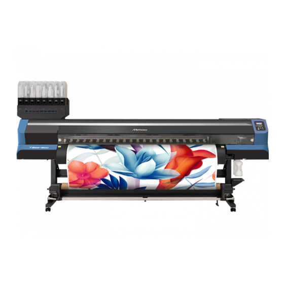
Congratulations on your purchase of MIMAKI color ink jet DISCLAIMER OF WARRANTY printer "TS55-1800". "TS55-1800" is a color inkjet printer that can print on THIS LIMITED WARRANTY OF MIMAKI SHALL BE THE SOLE 1.8m-width media with sublimation dye ink (4-color, 6- AND EXCLUSIVE WARRANTY AND IS IN LIEU OF ALL color, 7-color and 8-color). -
Page 7: Safety Precautions
Safety Precautions Safety Precautions Symbols In this document, symbols are used for explaining the contents of cautions on operation. The symbol to be displayed differs depending on the caution content. Please understand the meaning of each symbol and use this machine safely and correctly. Symbol Name Explanation... - Page 8 • Unplug the cord from the wall outlet and MIMAKI for repair. remove dust from the power plug periodically, • Never repair your machine by yourself since it at least once a year.
- Page 9 Safety Precautions Caution Caution Notes When Handling this machine Handling of ink packs • Use the equipment in a well-ventilated or not- • Keep ink away from an open flame. Also keep airtight room. the room well ventilated when you use or •...
- Page 10 Warning Warning Handling of media Notes on maintenance • Use media recommended by MIMAKI to ensure • It is strongly recommended to use the machine in a reliable, high-quality printing. room that is not dusty. • Set the heater temperature to meet the characteristics •...
-
Page 11: Safety Interlock
Safety Precautions Safety interlock This machine is equipped with interlocks to terminate the operation for your safety when the cover opens during printing etc. (red circle parts in the figure below). -
Page 12: Warning Labels
Warning labels Warning labels Warning labels are stuck on the machine. Be sure to fully understand the warning given on the labels. If a warning label is illegible due to stains or has come off, purchase a new one from a distributor or our sales office. When the carriage out When the front cover is open When the maintenance cover is open... - Page 13 Warning labels Reorder Label Description There is a possibility that the cover falls suddenly. When opening or closing the M910931 cover, keep away your body from the both ends of the cover. It is the carriage moving part. Do not bring your fingers and M907833 body close.
- Page 14 Warning labels xiii...
- Page 15 Chapter 1 Before Use This chapter describes the items required to understand before use, such as the name of each part of the machine or the installation procedures. Moving This Machine ........1-2 Connecting Cables........1-9 Where to Install This Machine ..... 1-2 Connecting the LAN cable ......1-9 Working Environmental Temperature ..
-
Page 16: Chapter 1 Before Use
3240mm 713mm 1,857 mm 202 kg • When moving this machine, take care that it does TS55-1800 (127.6 in) (28.1 in) (73.1 in) (445.3 lb) not receive a significant impact. • Be sure to lock the casters after moving of this machine. - Page 17 Chapter 1 Before Use Raise the adjuster foot of the roll guide Lower the front leg adjuster foot with the stay. attached adjustable angle wrench. Move this machine as shown in the figure. • When the installation floor is a soft •...
-
Page 18: Names Of Parts And Functions
Chapter 1 Before Use Names of Parts and Functions Front Side of the Machine Maintenance cover (upper) Open the cover in maintenance. Even when the power switch is off, keep all covers closed. Front cover Open the cover in setting of medias, taking of measures against jamming of medias or in Ink cartridges maintenance inside the station. -
Page 19: Rear Side And Right Side Of The Machine
Chapter 1 Before Use Rear Side and Right Side of the Machine Clamp lever (rear) Interlocks with the clamp lever in the font of this machine. Top blower Suppress upward floating of the ink mist that occurs during printing. Roll holders Putting this into the paper core (right and left) of a roll media, hold the media. -
Page 20: Operation Panel
Chapter 1 Before Use Operation Panel Use the operation panel to make settings for printing or operate this machine. Display Local <Setup 1> Changes over the functions of the Displays the following items: function keys ([FUNC1]–[FUNC3]). width:1340mm • Printer status 1620mm POST1 POST2... - Page 21 Chapter 1 Before Use *2 : Functions assigned to [FUNC1] to [FUNC3] Contents of functions assigned to [FUNC1] to [FUNC3] are described below. Icon Contents Displays "MENU" for setting functions. Displays maintenance functions such as test print, cleaning, etc. Shifts to REMOTE from LOCAL and starts printing. Displays adjustment functions such as FEED COMP, DROP.POScorrect, etc.
-
Page 22: Media Sensor
Chapter 1 Before Use Media sensor Capping station The media sensor detects the presence of the media and the The capping station consists of the ink caps, the wiper for media length. cleaning the heads, etc. This machine has two media sensors on the platen (in the rear). The ink caps prevent the nozzles in the ink heads from drying up. -
Page 23: Connecting Cables
Chapter 1 Before Use Connecting Cables • Change the mounting position of the clamp switching slider according to the media width. Connecting the LAN cable • When installed the clamp switch slider, clamps up, and when removed, clamps down. When connecting LAN cable, be sure to follow the note below: •... -
Page 24: Connecting Usb2.0 Interface Cable
Chapter 1 Before Use Notes on USB 2.0 Interface (1) Check the printer screen display. • On the local screen or the media detection screen, press the [Enter] key several times to display the information • Your RIP must be compatible with USB 2.0. screen. -
Page 25: Connecting The Power Cable
Chapter 1 Before Use Setting Ink Connecting the power cable You can use aqueous sublimation dye ink (Sb610) for this Insert the power cable into an inlet of the machine. machine. Inlet Take out the 2L ink pack. • Take out the 2L ink pack and the ink IC chip from a small cardboard box. - Page 26 Chapter 1 Before Use (3) Put the 2L ink pack facing the connector Hold the cap of the ink bottle tightly with a paper down, and close the 2L eco case. towel, and gently shake the 2L ink pack. Repeat groove part •...
- Page 27 Chapter 1 Before Use Replacing the 2L Ink Pack Mount the ink IC chip supplied with the replacement 2L ink pack. Perform as follows when [INK END] or [INK NEAR END] is displayed on the display. • Be careful not to touch the metal part of the ink IC chip.
-
Page 28: Caution In Handling Of Ink Packs
When this expiration date is exceeded, a message is in troubles. displayed in LOCAL and for the guidance message. MIMAKI will not bear any responsibility for any P.5-8, P.5-10) damage caused by the use of the ink packs You can use the cartridge in two months after the refilled with ink. -
Page 29: Media
Caution in handling of medias Pay attention to the followings for handling of medias. • Use media recommended by MIMAKI to ensure reliable, high-quality printing. Repeat Set the heater temperature to meet the characteristics of the media. -
Page 30: Menu Mode
Chapter 1 Before Use Menu mode This machine has 4 modes. Each menu mode is described below. NOT-READY mode This is the mode in which the media has not been detected yet. LOCAL mode Local mode is the mode for the drawing preparation state. All the keys are effective. - Page 31 Chapter 2 Basic Operations This chapter describes procedures and setting methods for ink and media preparation, and printing. Workflow ............2-2 Head Cleaning ..........2-11 Turning the Power ON/OFF ......2-3 About head cleaning ........2-11 Perform head cleaning depending on the test Turning the Power ON ........
-
Page 32: Chapter 2 Basic Operations
Chapter 2 Basic Operation Workflow Turning the Power ON/OFF Referring to "Turning the Power ON/OFF" P.2-3). Setting a Media Referring to "Setting a Media" ( P.2-4). Test Printing Referring to "Test Printing" ( P.2-10). Head Cleaning Referring to "Head Cleaning" ( P.2-11). -
Page 33: Turning The Power On/Off
Chapter 2 Basic Operation Turning the Power ON/OFF Turn the power off, by giving the key a long press. • Do not turn OFF the main power switch located Turning the Power ON on the side of the machine. • To use this machine again, press the [END/ This machine is provided with the following two power POWER] key. -
Page 34: Setting A Media
Chapter 2 Basic Operation Setting a Media Open the front cover. This machine can be used with a roll media. For usable medias, refer to P.1-15 "Usable sizes of media". • Take care not to drop the media on your foot when setting the media.It may cause an injury due to the media. -
Page 35: Setting A Roll Media
Chapter 2 Basic Operation If setting the media in the center Setting a roll media • Move the roll holder so the media’s set position is in the center of this machine. Set a roll media to the roll media hanger located on the back of this machine. - Page 36 Chapter 2 Basic Operation Loosen the screw of the right side roll • If you set the roll media in the center, to prevent the holder then insert the holder into the core media from moving, pull down the roll stopper of the roll media.
- Page 37 Chapter 2 Basic Operation Hold the media with the media press gently. • Set the media so that no media sticks out from the right end pinch roller to the right side. • When using a thick media, remove the media press from the media before printing.
-
Page 38: Take-Up Device
Chapter 2 Basic Operation Take-up device With the switch of the narrow take-up device, select the take-up direction of the media or others. Direction selector ON/ OFF button switch The take-up device winds the media with the printed side facing (REVERSE) Direction selector... -
Page 39: Changing The Printing Origin
• The printing origin is changed. • TS55-1800 has two heaters (POST 1 and POST 2) and an optional external heater in the main unit. Normally, printing is possible at ±3°C of Typical setting position of printing the set temperature. -
Page 40: Test Printing
Chapter 2 Basic Operation Test Printing • Press [FUNC3] (OFF) in Step 2 to turn all heaters OFF. Print a test pattern to check that there are no discharging Or, press [FUNC1] to raise the POST1/ POST2 heaters in 10°C increments. defects such as nozzle clogging (slight touching of ink or nozzle missing). -
Page 41: Head Cleaning
Chapter 2 Basic Operation Head Cleaning Press the (TEST PRINT/CLEANING) , and then press the key in LOCAL. • The test pattern orientation screen will be displayed. About head cleaning Press to select the test pattern Check the printed test pattern result and perform cleaning orientation (SCAN DIR./ FEED DIR.). -
Page 42: Setting Of Media Correction
Chapter 2 Basic Operation Setting of Media Correction If the Positions of Dots Shift... Correct the media feed amount to match the type of media you are using. If the correction value is not appropriate, stripes may When the condition for printing (media thickness/ink type/ appear on the printed image, thus resulting in a poor etc.) has been changed, perform the following operation printing. -
Page 43: Printing Data
Chapter 2 Basic Operation Printing Data Stopping a Printing Operation Perform the following operation when stopping a printing Starting a Printing Operation operation halfway. Press the (LOCAL) during printing. • When using a roll media, rewind the media by hand before printing so that it is not loose.When •... - Page 44 Chapter 2 Basic Operation 2-14...
- Page 45 Chapter 3 Setup This chapter describes the various setting of this machine. About SETUP MENU ........3-2 Setting a LANGUAGE........ 3-15 Setting a Time..........3-15 SETUP MENU table........3-3 Setting Unit (Temperature/ Length) ... 3-16 Register the optimal print conditions to match Setting a KEY BUZZER ......
-
Page 46: Chapter 3 Setup
Chapter 3 Setup About SETUP MENU On SETUP MENU, you can set the print conditions to match the media you usually use. : Press this to select SETUP MENU, or to switch to the previous screen. Local <Setup 1> : Press this to switch to the next screen. : Use these to select a setting item. -
Page 47: Setup Menu Table
Chapter 3 Setup SETUP MENU table • For each setting item below, you can set it so that the machine may operate according to the value specified when you printed from your RIP software in the connected host PC. • Set Item : LOGICAL SEEK/ Overprint/ DRYING TIME/ MARGIN (LEFT and RIGHT)/ VACUUM FAN/ FEED SPEED •... -
Page 48: Register The Optimal Print Conditions To Match The Use
Chapter 3 Setup Register the optimal print conditions Setting of Media Correction to match the use Correct the media feed amount to match the type of media you are using. In this machine, you will be able to register print If the correction value is not appropriate, stripes may conditions, SETUP 1 to 4 individually to match the media appear on the printed image, thus resulting in a poor... -
Page 49: If The Positions Of Dots Shift
Chapter 3 Setup Correcting Media-feeding during Printing If the Positions of Dots Shift... A media-feeding rate can be corrected even in the remote When the condition for printing (media thickness/ink type/ mode or when image data is printed. etc.) has been changed, perform the following operation to correct the ink drop position for bidirectional (Bi) Press in the... -
Page 50: Setting The Heater
Chapter 3 Setup Setting the HEATER Setting of Logical Seek Post-heater 1and Post-heater 2 are equipped on the The head’s operation varies depending on the LOGICAL platen. SEEK settings, as shown in the figure below. Type of HEATER Function Movement of heads when LOGICAL seek is OFF POST1 Warm up the media after printing. -
Page 51: Setting Of Drying Time
Chapter 3 Setup Press to select "Overprint" , and Setting of Left and Right Margins press the the key. Set a non-printing area along the left and right edges of Press to set number of Overprint, the media. and press the the key. -
Page 52: Setting Of Feed Speed
Chapter 3 Setup press the key several times to Setting Auto Cleaning end the setting. You can set the machine so that it counts the number of printed files or the length or time after printing has been completed, and performs cleaning automatically if required. Suction fan always on You can select the auto cleaning setting from three types below:... -
Page 53: Setting External Heater
"MANUAL", and Setting of MAPS4 press the key. The MAPS (Mimaki Advanced PassSystem) function to • To select "AUTO" for the setting, refer to P.3-9 disperse the pass boundary to make the feeding stripes "Setting MAPS4 Function (AUTO)". -
Page 54: Pass Density Correct
Chapter 3 Setup Press the key several times to Press the key several times to end the setting. end the setting. Pass density correct Change of setting type name If periodic shading differences are noticeable between You can change the name of the setting type. passes, it can be reduced by changing this setting. -
Page 55: About Machine Setup Menu
Chapter 3 Setup About MACHINE SETUP MENU Common settings are functions for using this machine easily. The following items can be set in machine setups. : Press this to select MACHINE SETUP MENU, or to switch to the previous screen. Local <Setup 1>... -
Page 56: Machine Setup Menu Table
Chapter 3 Setup MACHINE SETUP MENU table Function name Set value Meaning When no operation has been performed for the NONE/ AUTO Power-off ( P.3-14) set time, the power supply is automatically 10 ~ 30~ 600min turned "OFF". Sub take-up unit ON/ OFF Set whether or not to use sub take-up unit. - Page 57 Chapter 3 Setup Function name Set value Meaning Mail Delivery Set whether you send/ do not send the e-mail ON / OFF P.3-18) when the set event occurs. Print Start Set whether you send/ do not send the e-mail at ON / OFF Event the start of printing.
-
Page 58: Setting A Auto Power-Off
Chapter 3 Setup Setting a AUTO Power-off Setting Top Blower When no operation has been performed for the set time, Set the operation of the top blower in print. the power supply is automatically turned "OFF". Turn the top blower setting "ON", and you can set the strength for the blower. -
Page 59: Setting The Media Detection
Chapter 3 Setup Press the key several times to Press to select "High / Normal", end the setting. and press the key. • Set value: High / Normal • When set "ON" the media remaining • High: Media retainer auto detection is display, you can print the list of current provided media remaining amount and the date. -
Page 60: Setting Unit (Temperature/ Length)
Chapter 3 Setup Press to select a set value, and Setting Unit (Temperature/ Length) press the key. Units used by this machine are set. • Set value : ON/ OFF Press Press the key several times to (MENU) (twice) in LOCAL. end the setting. -
Page 61: Set The Network
Configurator", the tool to perform network setting of DEFAULT GATEWAY/ DNS ADDRESS/ SUBNET Mimaki’s product. To download the Network Configurator, MASK. For other than above, proceed to the Step check "Driver/Utility" on the download page at Mimaki Engineering (https://mimaki.com/download/). Press several times to select setting... - Page 62 Chapter 3 Setup Enable the event mail function Press the key several times to end the setting. Press (MENU) (twice) in LOCAL. Set the e-mail address • MACHINE SETUP MENU will be displayed. Press (<<) . Press (MENU) (twice) in LOCAL. Press to select "EVENT MAIL", •...
- Page 63 Chapter 3 Setup Set the server Press to set Pass Word, and press the key. Press (MENU) (twice) • Press [][][][] to set the password to use for the authentication. in LOCAL. • Set it with alphanumeric characters and symbols •...
- Page 64 Chapter 3 Setup Send a test e-mail Press the key. • The sent result is displayed. • If sending test e-mail has failed, an error code is Press (MENU) (twice) displayed. in LOCAL. Refer to the next page to solve the problem. •...
-
Page 65: Automatic Remote
Chapter 3 Setup Automatic remote Press to select "ON / OFF", then press the key. When data is received in local mode, it automatically • ON: When you want to light up when the switches to remote mode and starts printing. machine is activated •... - Page 66 Chapter 3 Setup Press the key. • The already configured settings are initialized. Press the key several times to end the setting. 3-22...
-
Page 67: About Nozzle Check Menu
Chapter 3 Setup About NOZZLE CHECK MENU Set operations concerning the nozzle missing detection function. : Press this to select INFORMATION MENU, or to switch to the previous screen. Local <Setup 1> : Press this to switch to the next screen. : Use these to select a setting item. -
Page 68: Printing Check Flow
Chapter 3 Setup Printing Check Flow Nozzle check is conducted according to the following flow at the start of printing. • Turn the "Printing Check" setting ON to be enabled. • Only perform RETRY COUNT and Printing Check settings when the settings are enabled. nozzle check ... -
Page 69: Setting The Printing Check
Chapter 3 Setup Setting the Printing Check Setting the NOZZLE RECOVERY Select ON when you want to conduct nozzle check at the set this if you want to conduct automatic nozzle recovery start of online printing. when nozzle missing is detected. Press Press (MENU) -
Page 70: About Information Menu
Chapter 3 Setup About INFORMATION MENU The information of this machine can be confirmed. The following items can be confirmed as machine information. : Press this to select INFORMATION MENU, or to switch to the previous screen. Local <Setup 1> : Press this to switch to the next screen. -
Page 71: Displaying The Information
Chapter 3 Setup Displaying the Information Press (MENU) (4 times) in LOCAL. • INFORMATION MENU will be displayed. Press to select a information. • Refer to the "INFORMATION MENU", and select the information to be displayed. Press the key. • If you selected [LIST] in step 2, the machine’s settings will be printed. - Page 72 Chapter 3 Setup 3-28...
- Page 73 Chapter 4 Maintenance This chapter describes the items required to use this machine more comfortably, which are the methods for the daily care, the maintenance of the ink cartridges etc. Maintenance ..........4-2 Set Whether to Enable NOZZLE RECOVERY During TEST PRINT ........4-15 Precautions for Maintenance ......
-
Page 74: Chapter 4 Maintenance
Chapter 4 Maintenance Maintenance Cleaning the Exterior Surfaces Maintain the machine regularly or as necessary so that its When the exterior surfaces of the machine are stained, dampen a soft cloth with water or a neutral detergent accuracy will be maintained and it can continue to be used for a long time. -
Page 75: Cleaning The Media Sensor
Chapter 4 Maintenance Cleaning the Media Sensor • If ink adheres to the end face of the media and becomes dirty, be sure to clean it. • If ink adheres frequently, we recommended to set The media sensors are located on the platen in the the vacuum fan to "weak"... -
Page 76: About Maintenance Menu
Chapter 4 Maintenance About MAINTENANCE MENU This provides various settings for performing maintenance. The following items can be set in MAINTENANCE settings. : Press this to select MACHINE SETUP MENU, or to switch to the previous screen. Local <Setup 1> : Press this to use the maintenance function. -
Page 77: Maintenance Menus Table
Chapter 4 Maintenance MAINTENANCE MENUs table Item Setting Value Meaning For carrying out maintenance on the carriage and station periphery. CARRIAGE OUT Moves the carriage out, for carrying out cleaning of the cap periphery, P.4-6) head, wipers, etc. NOZZLE WASH Soaks the nozzle surfaces in maintenance cleaning fluid, for carrying 1 to 99 min. -
Page 78: Maintaining The Capping Station
Chapter 4 Maintenance Maintaining the Cap- Press to select "CARRIAGE OUT", and press the key. ping Station • The carriage moves over the platen. Maintain the ink cap, wiper, etc. located in the capping Open the front cover. station. (STATION MAINTENANCE) •... -
Page 79: Cleaning The Cap
Chapter 4 Maintenance Set the wiper at the original position. Open the front cover. • Insert the wiper by holding the protrusions at both ends. • Be sure to insert it all the way in. The wiper may come off and the machine may be damaged. -
Page 80: Nozzle Cleaning
Chapter 4 Maintenance Press to select "CARRIAGE When "WIPER CLEANING" is indicated on OUT", and press the key. the display, open the front cover and the right maintenance cover. • The carriage moves over the platen. Open the front cover. Clean the wiper, and press the key. -
Page 81: Cleaning The Ink Discharge Passage
Chapter 4 Maintenance • When the cleaning liquid cartridge is not Cleaning the Ink Discharge Passage enabled, the cap is not automatically filled with cleaning solution. In order to prevent ink clogging due to coagulation inside Open the front cover and fill the cap with the ink discharge passage, clean the ink discharge the maintenance cleaning solution using passage periodically. -
Page 82: When The Machine Is Not Used For A Long Time
Chapter 4 Maintenance When an "Operations complete" message Press (MENU) in LOCAL. is displayed, open the front cover and check the amount of cleaning solution in Press to select the cap. "MAINTENANCE", and press the key. • Maintenance menu will be displayed. Press to select "STATION MAINT.", and press the... - Page 83 Chapter 4 Maintenance • If the cleaning solution is not full of cap, fill the cap Clean the cap rubber. with the maintenance cleaning solution with a • Wipe off the ink sticking to the cap rubber with a dropper. clean stick dipped in cleaning solution for maintenance.
-
Page 84: Cleaning The Ink Head And The Area Around It
Chapter 4 Maintenance Cleaning the Ink Head When an "Operations complete" message is displayed, open the front cover and and the Area Around It check the amount of cleaning solution in the cap. Because the ink head employs a very precise mechanism, due care needs to be taken when it is cleaned. -
Page 85: Nozzle Recovery Function
Chapter 4 Maintenance Nozzle Recovery Func- Use a clean stick to wipe ink off the head surface. tion • Never rub the nozzles. When missing nozzles cannot be improved at specific points, other good nozzles can be used as alternatives for printing. -
Page 86: Reset The Set Value
Chapter 4 Maintenance Specify the position of nozzle missing. Register the Nozzle number that needs NOZZLE RECOVERY, and press the • Locate the missing nozzle with the right scale and key. the upper scale. • If you select "Register", without going to print, go (1) Press [][] to select the registration to the nozzle row selection procedure (step 9). -
Page 87: Check Conditions For Which Nozzle Recovery Cannot Be Performed
Chapter 4 Maintenance If nozzle recovery Check Conditions for Which Nozzle possible Judgement result Recovery Cannot be Performed Judgement result Press (MENU) in LOCAL. Press to select If nozzle recovery is not possible Judgement result "MAINTENANCE", and press the key. Judgement result HEAD1-A •... -
Page 88: Auto Maintenance Function
Chapter 4 Maintenance Auto Maintenance Setting the Cleaning Intervals and Function Type The cleaning type and the interval between each cleaning To get the best out of this machine, you can set various operation are set. maintenance operations to be performed automatically. Press (MENU) in LOCAL. -
Page 89: Replacing Consumables
Chapter 4 Maintenance Replacing Consum- Remove the wiper. ables • Pull out the wiper by holding the protrusions at both ends. Protrusion Replacing the Wiper When the display indicates the warning message "REPLACE WIPER", it is necessary to replace the wiper with a new one as soon as possible. -
Page 90: Replacing The Cap
Chapter 4 Maintenance Open the front cover. Attach the fitting. Carriage Remove the fitting. When replacement is complete, press the • Pull out the fitting by holding the protrusions at key. both ends. Close the front cover, and press the key. -
Page 91: Replacing The Cap Absorber
Chapter 4 Maintenance Remove the Cap. Open the front cover. • Pull it up while pushing in the protrusion of the cap. Carriage Remove the Cap Absorber. Attach a new Cap. • Remove the clasps at the front (3 points) and pull it out. -
Page 92: Replacing The Media Press
Chapter 4 Maintenance Open the maintenance cover. Replacing the Media Press If the media press (PN:SPC-0789) becomes deformed and rubs against the head, you need to replace it. • The media press is an optional item. You can buy one through your local dealer or from our service office. -
Page 93: Replacing The Pinch Roller
Chapter 4 Maintenance Attach the slider to the new media press. Turn the main power switch ON. • Hook the hole of the slider on the protrusion of the (1) Set the main power switch located on the media press. side of this machine to the "I"... - Page 94 Chapter 4 Maintenance Turn off main power switch. Insert the O-ring. • Tilt the main power switch on the side of the unit to "" side. Main power switch Close the front cover. Open the front cover. Turn the main power switch ON. Raise the clamp lever to keep the pinch (1) Set the main power switch located on the roller lifted.
-
Page 95: Replacing The Carriage Filter
Chapter 4 Maintenance Remove the Carriage filter. Replacing the Carriage filter Replace the Carriage filter (PN:SPC-0844) when it gets too dirty. • The Carriage filter is an optional item. You can buy one through your local dealer or from our service office. -
Page 96: Male Connector Absorbent For Mbis
Chapter 4 Maintenance Install the 2L eco-case. Male Connector Absorbent for MBIS When replacing the 2L ink pack, you can prevent dirt from entering the cradle by periodically (5 to 10 times) replacing the male connector absorbent (accessory). • Be sure to wear the supplied safety glasses and gloves when replacing the male connector absor- bent. -
Page 97: Replacing The Cutter Blade
Chapter 4 Maintenance Replace the cutter unit next to the carriage. Attach a new Blow down fan filter and return the fan filter cover. (1) Loosen the screw of the cutter unit. • Fit the fan filter cover on firmly, so that it clicks into (2) Remove the cutter unit. -
Page 98: Waste Ink Tank Management
Chapter 4 Maintenance Waste ink tank man- If a Waste Ink Tank Confirmation agement Message Appears Ink that is used for head cleaning is collected in the waste ink tank on the bottom right side of this machine. This Correction of waste ink amount machine keeps track of the total volume of ink that is discharged, and displays a confirmation message when a If an error occurs between the count value of the waste... - Page 99 Chapter 4 Maintenance • The MAINTENANCE menu is displayed. Press to select " Reset Waste Ink Volume", and press the key. • Waste ink tank information is displayed. Empty waste Follow the instructions displayed on the ink tank screen to replace the waste ink. Press the key.
- Page 100 Chapter 4 Maintenance 4-28...
- Page 101 Chapter 5 Troubleshooting This chapter describes the corrective measures to be taken for a phenomenon suspected to be trou- ble and the procedures to clear the error number displayed on the LCD. Troubleshooting ................5-2 Power does not turn on ..............5-2 The machine does not start printing ..........
-
Page 102: Chapter5 Troubleshooting
Troubleshooting Take appropriate actions as described below before taking the trouble as a failure. If still the problem is not solved after troubleshooting, contact your dealer or an office of MIMAKI. Power does not turn on In most cases, this is due to improper connection of the power cable for the machine or computer. Check that the power cable is connected properly. -
Page 103: The Heater's Temperature Will Not Rise To The Set Level
• Once ink trouble is displayed, do not leave the ink pack without replacing it for a long time; otherwise, the machine will lose the nozzle clogging prevention function. If nozzles are clogged, the machine must be repaired by MIMAKI's service engineer. Displaying the description of ink IC trouble The contents of IC error are confirmable by the following operations. -
Page 104: When The Ink Leakage Occurs
Chapter5 Troubleshooting When the ink leakage occurs In case of ink leakage, please turn off the main power, unplug the power cable and contact your local distributor, our sales office, or service center. -
Page 105: Warning / Error Messages
Chapter5 Troubleshooting Warning / Error Messages If some trouble occurs, the buzzer sounds and the display shows a corresponding error message. Take an appropriate measure for the displayed message. Warning messages Error displaying information Illustration Display Measures • It is an ink end. Set Cartridge Replace the ink pack and ink IC chip. - Page 106 Chapter5 Troubleshooting Illustration Display Measures <Alternate display 1> Please replace wash liquid cartridge • Replace the maintenance washing liquid cartridge. <Alternate display 2> • Set the maintenance washing liquid car- No washing liquid will cause cleaning tridge. failure • Replace the wiper. (MAINTENANCE Replace Wiper MENU>...
- Page 107 Chapter5 Troubleshooting Illustration Display Measures • Check the position of the extension heater. Please set the ext.heater to the correct (make sure to set correct vertical position, position and not set in halfway position) Errors when performing operations Display Cause Measures Invalid Operation The function cannot be executed...
- Page 108 Chapter5 Troubleshooting Display Cause Measures The function cannot be executed Invalid Operation because the connection between take- Take-up Connect up and feeding is reversed. The function cannot be executed Invalid Operation because the connection between feed- Feeding Connect • Restart the unit. ing and take-up is reversed.
- Page 109 Chapter5 Troubleshooting Display Cause Measures • Replace the ink pack or 10kg ink tank and Ink Expiration Over M_ _ _ _ _ _ The ink has expired (less than 2 months ink IC chip. from expiration). (It can be used from the expiration date up to 2 months.) Replace the Spout Rubber of Spout rubber of eco-case is time to...
- Page 110 Chapter5 Troubleshooting Display Cause Measures • Clean around the wiper and restart the machine. Wiper Move Failure The wiper does not operate normally. If displaying again, contact your local distrib- utor, our sales office, or service center. The NCU is not connected. •...
-
Page 111: Error Message
(The remaining ink level in the tank is less than 25%.) Error message When an error message is displayed, eliminate the error according to the chart below. When displaying again, contact your dealer or an office of MIMAKI to call for service. Display Cause Measures... - Page 112 Chapter5 Troubleshooting Display Cause Measures ERROR 171 An error occurred in the power supply NEW HEAD CONNECT system of the main PCB. ERROR 18a Main PCB V_CORE An error occurred in the power supply of the main PCB. ERROR 18c Main PCB V12 ERROR 18e FLS NOT COMP...
- Page 113 Chapter5 Troubleshooting Display Cause Measures ERROR 402 An excessive load was applied to the Y MOTOR Y motor. • Turn off the power on the machine and turn it ERROR 403 Overcurrent error of X motor was on after a while. X CURRENT detected.
- Page 114 Chapter5 Troubleshooting Display Cause Measures The NCU sensor sensitivity is too low to correctly judge missing lines (due to noz- • NCU replacement is required. ERROR 651 zle clogging). Contact your local distributor, our sales REPLACE NCU The nozzle check function cannot be office, or service center.
- Page 115 Chapter5 Troubleshooting SYSTEM HALT Message Solution • Turn off the power on the machine and turn it on after a while. SYSTEM HALT (*) When displaying again, check the number and contact your local distributor, our sales 000 : MESSAGE office, or service center.
- Page 116 Chapter5 Troubleshooting 5-16...
- Page 117 Chapter 6 Appendix This chapter contains the lists of the specifications and functions of this machine. Specifications ..................6-2 Machine specifications ..............6-2 Ink specifications ................6-3 Setting orders depending on ink type ..........6-4 Setting orders of ink cartridges ............6-4 Sheet for inquiry ................6-5...
-
Page 118: Chapter 6 Appendix
Chapter6 Appendix Specifications Machine specifications Item TS55-1800 Method Drop-on-demand piezoelectric print heads Print head Specification 4-Head 360×360dpi/ 480×600dpi/540×360dpi/ 600×600dpi/720x600 /720×720dpi/ Printing mode (scan x feed) 720×1080dpi Usable inks 9 colors (Y, M, Bl, K, LBl, Lm, Lk, FP, FY) Supplying from ink packs through tubes. -
Page 119: Ink Specifications
Chapter6 Appendix Item TS55-1800 VCCI-Class A, FCC-Class A, UL 60950, CE Marking (EMC,Low Voltage Directive, Safety Standard Machinery Directive, RoHS Directive), CB Report, RoHS, Energy Star, RCM, EAC Power Single-phase AC100 - 120V/ 200 - 240V 12A/8A 50/60Hz Power consumption 1440 W or less (AC 100 - 120 V), 1920 W or less (AC 200 - 240 V) Available temp. -
Page 120: Setting Orders Depending On Ink Type
Chapter6 Appendix Setting orders depending on ink type The setting value and the setting orders of the ink cartridges differ depending on the ink type you use. Setting orders of ink cartridges The orders of ink cartridges set in the ink station differ depending on the ink set you use. •... -
Page 121: Sheet For Inquiry
Chapter6 Appendix Sheet for inquiry Use this sheet for troubles and abnormal functions of the machine. Fill in the following necessary items, and then fax the sheet to our sales office. Company name Person in charge Telephone number machine model Operating OS Machine information Error message... - Page 122 Chapter6 Appendix...
- Page 123 TS55-1800 Operation Manual March, 2019 MIMAKI ENGINEERING CO.,LTD. 2182-3 Shigeno-otsu, Tomi-shi, Nagano 389-0512 JAPAN D203290-15-20032019...
- Page 124 FW : 1.00 © MIMAKI ENGINEERING CO., LTD.2018...
Need help?
Do you have a question about the TS55-1800 and is the answer not in the manual?
Questions and answers