
Related Manuals for MIMAKI TS500-1800


Summary of Contents for MIMAKI TS500-1800
- Page 1 MIMAKI ENGINEERING CO., LTD. URL: http://eng.mimaki.co.jp/ D202330-13 Original instructions...
-
Page 2: Table Of Contents
TABLE OF CONTENS CAUTION ................v DISCLAIMER OF WARRANTY ........v Requests ................. v FCC Statement (USA) ............. v Interference to televisions and radios ......v Foreword ................vi About usable ink ..............vi On This Operation manual ..........vi Safety Precautions ............. vii Symbols ................vii Safety interlock .............. - Page 3 Changing the printing origin ..........2-25 Preparing for the Heaters ..........2-26 Changing the Temperature Settings for the Heaters ..2-26 Checking the Heater Temperature .........2-27 Test Feeding ..............2-28 Test Printing ..............2-29 Test Printing ..............2-30 Head Cleaning ..............2-31 About head cleaning ............2-31 Perform head cleaning depending on the test printing result 2-31 Set the media feeding .............
- Page 4 Chapter 4 Maintenance Maintenance ..............4-2 Precautions for Maintenance ..........4-2 About Cleaning Solution ........... 4-2 Cleaning the Exterior Surfaces ......... 4-3 Cleaning the Platen ............4-3 Cleaning of post heater cover and rear platen cover ..4-3 Cleaning the Media Sensor ..........4-4 Cleaning the Media Press ..........
- Page 5 Chapter 6 Appendix Specifications ..............6-2 Machine specifications ............6-2 Ink specifications ..............6-3 Setting orders depending on ink type ....... 6-4 Setting orders of ink bottles ..........6-4 Sheet for inquiry ..............6-5 Warning labels ..............6-6 Function Flowchart ............6-8...
-
Page 6: Caution
Operation of this equipment in a residential area is likely to cause harmful interference in which case the user will be required to correct the interference at his own expense. In the case where MIMAKI-recommended cable is not used for connection of this device, limits provided by FCC rules can be exceeded. -
Page 7: Foreword
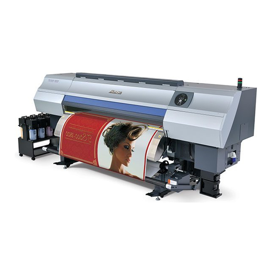
Foreword Congratulations on your purchase of MIMAKI color ink jet printer "TS500 Series" . “TS500 Series” is a color inkjet printer that can print with Sublimation dye ink realizing high speed and high image quality. About usable ink Usable ink for this machine is Sublimation dye ink (four-color / six-color model). -
Page 8: Safety Precautions
Safety Precautions Symbols Symbols are used in this Operation Manual for safe operation and for prevention of damage to the machine. The indicated sign is different depending on the content of caution. Symbols and their meanings are given below. Please follow these instructions as you read this manual. Examples of symbols Meaning Failure to observe the instructions given with this symbol can result in death or serious injuries... -
Page 9: Warning For Use
Check first that the machine no longer produces smoke, and then contact your distributor or a sales office of MIMAKI for repair. Never repair your machine and ink bottle by yourself since it is very dangerous for you to do so. -
Page 10: Cautions And Notes
• The machine does not operate with any ink other than the Handling of media TS500 genuine ink. • Use media recommended by MIMAKI to ensure reliable, • Do not use the TS500 genuine ink with other printers, as high-quality printing. -
Page 11: Safety Interlock
Safety Precautions Cautions on Installation CAUTION A place exposed to direct A place where temperature or On an inclined surface sunlight humidity varies significantly • Use the machine under the following environmental conditions: • Operating environment: 20 to 30 °C (68 to 86 °F) 35 to 65 % (Rh) A place exposed to direct air Around a place where fire is... -
Page 13: Before Use
Chapter 1 Before Use This chapter describes the items required to understand before use, such as the name of each part of the machine or the installation procedures. About installing this machine ......1-2 Connecting Cables ........1-10 Where to Install This Machine ..... 1-2 Connecting USB2.0 Interface Cable ..1-10 Working Environmental Temperature .. -
Page 14: About Installing This Machine
The place of installation must have enough space for not only this machine itself, but also for the printing operation. Model Width Depth Height Gross weight 3830mm 1700mm TS500-1800 750kg 1440mm External ink supply unit 775mm 490mm 785mm 30kg *1. When the tension bar is flat... -
Page 15: About Fixing Machine
About installing this machine About fixing machine The leg of this machine has the level foot to fix the machine. Before turning the power ON, make sure that the printer body is fixed with the leveling feet. The printer body may start moving during operation if it is not fixed with the leveling feet. -
Page 16: Names Of Parts And Functions
Names of Parts and Functions Front Side of the Machine Platen The printed media is sent out, sliding on the platen. Three heaters are installed inside the platen. Print heater/ Post-heater/ Post-heater Left maintenance cover Fixes and dries the ink on the currently produced print. Open the cover in maintenance. -
Page 17: Rear Side And Right Side Of The Machine
Names of Parts and Functions Rear Side and Right Side of the Machine Clamp lever (rear) Interlocks with the clamp lever in the font of this machine. Roll holders Putting this into the paper core (right and left) of a narrow roll medium (less than 1m), hold the medium. -
Page 18: Operation Panel
Operation Panel Use the operation panel to make settings for printing or operate this machine. CONSTANT lamp Lights in green when the heater temperature reaches the set Use this when setting media cut and the head gap. temperature. HEAT lamp Draws test patterns to check if there are any Lights in orange during heating up of the heater. -
Page 19: Heater
Names of Parts and Functions Heater Print heater and Post-heater are equipped on the platen. Print-heater Improves the image quality in printing. Dries ink after printing. Post-heater When you control cockling, turn OFF the Post-heater ) and use the Post-heater ) only, or, set the temperature of the Post-heater ) lower than that of the Post-heater ). -
Page 20: Carriage
Carriage The carriage is provided with the heads for printing, the cutter unit for cutting off the sheet of media, etc. Cutter blade and slot for cutting The carriage is provided with a cutter unit for cutting off the media that has been printed on. The cutter cuts off the sheet of media along the slot for cutting on the platen. -
Page 21: Capping Station
Names of Parts and Functions Capping station • Be sure to wear the attached goggles in cleaning within the capping station to protect your eyes against ink. Otherwise, you may get ink in your eyes. The capping station consists of the ink caps, the wiper for cleaning the heads, etc. -
Page 22: Connecting Cables
Connecting Cables Connecting USB2.0 Interface Cable Connect the PC and this machine with the USB2.0 interface cable. USB cable • Your RIP must be compatible with USB 2.0. • Contact a RIP maker near your location or our office when the USB2.0 interface is not attached to the PC. -
Page 23: Connecting Power Supply Cable
Copy the data onto the hard disk before outputting it for printing. Connecting Power Supply Cable You are not allowed to install the printer by yourself. Be sure to request MIMAKI’s service personnel and an electrician to install the printer. -
Page 24: Setting Ink Bottles
Setting ink bottles Set the ink bottle on the external ink supply unit. Catches Remove the ink cover. • Remove both catches of the ink cover and remove the cover. • The rear surface of the ink cover has the nozzle (stick shape) for ink absorption and the float sensor for detecting remaining amount of ink. - Page 25 Setting ink bottles Make slits in the top surface of the bottle as the figure, and push the aluminum sheet downward. • Use a cutter etc. to make slits in the top surface. How to make slits • When you make slits in the aluminum sheet, divide it into eight parts as shown in the figure, or, cut off the aluminum sheet along the inner side of the bottle.
-
Page 26: Changing An Ink Bottle
Changing an ink bottle Perform as follows when [INK END] or [INK NEAR END] is displayed on the display. When [INK END] is displayed Catches Remove the ink cover of the ink bottle to be changed, and remove the empty (used) ink bottle. •... - Page 27 Setting ink bottles Catches Set the ink bottle on the ink holder, and attach the ink cover. Insert the IC chip. When [INK NEAR END] is displayed There is a little of ink left. It is recommended to replace the ink bottle soon since ink may become empty in printing while printing is continuously enabled.
-
Page 28: Caution In Handling Of Ink Bottles
Setting ink bottles About ink expiration date The ink bottle has its expiration date. You can use the bottle in two months after the expiration date indicated on it, however, you cannot use it when three months have passed from the expiration date. When it becomes unusable, the ink bottle lamp blinks fast in red to inform you of it. -
Page 29: Media
• Do not leave the media with the heater ON for a long time. Waviness may occur on the media and it may cause media clogging. • Use media recommended by MIMAKI to ensure reliable, high-quality printing. Set the heater temperature to meet the characteristics of the media. - Page 30 1-18...
-
Page 31: Basic Operations
Chapter 2 Basic Operations This chapter describes procedures and setting methods for ink and media preparation, and printing. Workflow ............2-2 Head Cleaning ..........2-31 Turning the Power ON/OFF ......2-3 About head cleaning ........2-31 Perform head cleaning depending on Turning the Power ON ........ 2-3 the test printing result ........2-31 Turning the Power OFF ....... -
Page 32: Workflow
Workflow Turning the Power ON/OFF Referring to “Turning the Power ON/OFF” P.2-3). Setting a Media Referring to “Setting a Media” ( P.2-5). Preparing for the Heaters Referring to “Preparing for the Heaters” P.2-26). Test Feeding Referring to “Test Feeding” ( P.2-28). -
Page 33: Turning The Power On/Off
Turning the Power ON/OFF Turning the Power ON • Turn the power ON after the front cover and maintenance cover are closed. Turn the main power switch ON. • Set the main power switches located on the side of this Main machine to the “I”... -
Page 34: Turning The Power Off
Turning the Power ON/OFF Turning the Power OFF When having ended the operation of the machine, turn the power OFF by pressing the power button located on the front side. Check the following items when turning the power OFF. • If the machine is receiving data from the PC or if there is any data that has not been output yet •... -
Page 35: Setting A Media
Setting a Media This machine can be used with a roll media and leaf media. For usable medias, refer to P.1-17 “Usable sizes of media”. Setting the Head Gap Set the head gap (height from the media to the nozzle plane of the heads). When the carriage is to move above the platen for printing or maintenance, it moves while keeping the head gap at the preset value. -
Page 36: Note For Media Setting
Note for media setting When setting media, read the following notes carefully. • Take care not to drop the media on your foot when setting the media.It may cause an injury due to the media. • When setting a roll media, work by two or more people. Otherwise, you may hurt your back by the weight of the roll media. -
Page 37: Setting A Roll Media
Setting a Media Setting a roll media Prepare for the take-up device first Prepare for the take-up device before setting the roll media. • Handle the roll shaft with care, since it is very heavy with media. To avoid an accident or injury, Handle be sure to grip the handles on both ends. - Page 38 Remove the roll holders. • The roll holders are on both for the right and left of the roll holder. Remove both with the procedures below: (1) While lifting the lever of the roll holder stopper, rotate it Roll holder stopper to the position indicated in the figure.
-
Page 39: Setting A Media
Setting a Media Set the roll shaft with the paper core on the take-up device, and close the covers on the right and left sides of the roll shaft. • Fitting the A part of the roll shaft to the B part bearing of the machine, put it on. •... - Page 40 Setting a Roll Media Set a roll media to the feeding device on the back. When setting a roll media, set “Setting the feeding and take up” of the machine setting to “ON”. • Take care not to drop the media on your foot when setting the media. •...
- Page 41 Setting a Media Remove the roll holders. • The roll holders are on both for the right and left of the roll holder. Remove both with the procedures below: (1) While lifting the lever of the roll holder stopper, rotate it Roll holder stopper to the position indicated in the figure.
- Page 42 Put the roll shaft with the media on the feeding device. • Fitting the A part of the roll shaft to the B part bearing of the machine, put it on. • Do not close the cover yet. B part A part •...
- Page 43 Setting a Media Clamp lever Open the front cover and raise the clamp lever at the front of this machine. Front cover Slide the media from the back to the front. • Insert the roll media between the platen and the pinch roller, and slide it to the front.
-
Page 44: This Machine
Pull out the media. • Holding both sides of the media, pull it out so that the media top edge comes below the floor by about 50cm. • To set the media straight, pull out the media long. Check the position of the media edge surface and the feed roller. •... - Page 45 Setting a Media Push down the clamp lever. Adjust the position of the tension-bar with the switches on the left of the feeding device. (1) Set the switches to the take-up direction of the media. (2) Turn the left switch to [MANUAL]. •...
- Page 46 Press to select "ROLL" . MED I A S E L EC T ROL L < > L EA F • Detects the media width and thickness. • If the media thickness could not be detected, the error message is displayed. Enter the media thickness by referring to P.2-17 “When media thickness could not be detected”.
- Page 47 Setting a Media Press again to loose the media. • Loosen the media until it reaches to the floor. At the front, lift the tension- bar down slowly. • Unlock the tension-bar, and then lift it down. Rock Tension bar Press to lift the tension-bar up and to stretch the loosened media.
- Page 48 About entering media thickness and remaining amount When you set “Media remaining amount display” and “Media detection” to “ON” and “MANUAL” ( P.3- 16?P.3-23), input screen for the media thickness and the remaining amount is displayed after detecting the media width. Display the screen for entering media thickness.
- Page 49 Setting a Media Installing the counter weight for adjusting the take-up/ feeding tension-bar weight Install the proper number of the counter weight depending on the media type. Depending on the attaching position of the counter weight, you can adjust the tension bar weight. (If you attach it on the A part in the next pages figure, it may be heavier, and on the B part, it may be lighter.) You can attach the counter weight up to 5 each for right and left.
- Page 50 Setting a narrow roll media When you use narrow roll media (up to 1m), set the media on the narrow roll holder. When using the media take-up machine, be careful about the points below: • At the feeding side, set the printed surface to “revoluted” (inside out). •...
- Page 51 Setting a Media Loosen the screw of the right roll holder, and insert the holder into the paper core. Raise the clamp lever in the rear side of this machine. Insert the roll media in this machine. Pinch roller • The roll media can be smoothly inserted by slanting the media. (1) Pull the media out of the roll to the head of the platen.
- Page 52 Pull out the roll media out. (1) Open the front cover. (2) Raise the clamp lever from the front of this machine. (3) Pull out the roll media gently and then stop pulling when locked lightly. Check the position of the media edge surface and the feed roller. •...
- Page 53 Setting a Media (2) As indicated, fix the media on the paper core with tape so that the printed surface may be “involuted”. • Along the paper core, fix the media on several positions with tape in the order in the figure so that the media may not wrinkle.
-
Page 54: Setting Leaf Media
Setting leaf media Unlike roll media, leaf media does not need to be retained with the roll holders. Clamp lever Open the front cover. Raise the clamp lever. Front cover Insert the leaf media between the platen and the pinch rollers. •... -
Page 55: Changing The Printing Origin
Setting a Media Press the key. Press the key to select "LEAF" . MED I A S E L EC T RO L L < > L EA F The media detection is started. * * MED I A DE T EC T * * (1) The media width is detected. -
Page 56: Preparing For The Heaters
Preparing for the Heaters Changing the Temperature Settings for the Heaters Set the heater temperature. Depending on the media and the profile to use, set the heater temperature. • It may take several minutes to tens of minutes for the set temperature to be reached, depending on the ambient temperature. -
Page 57: Checking The Heater Temperature
Preparing for the Heaters Checking the Heater Temperature Press the key. PR T POS T 1 POS T 2 3 5 ° C 4 0 ° C 5 0 ° C • The current heater temperature is displayed. Press the key at the end of confirmation. -
Page 58: Test Feeding
Test Feeding Since heater is used at high temperature, cockles may occur in some of your media. ( P.5-11) Perform this function before printing, and check whether the media can be fed normally. Press the key in LOCAL three T E S T F E ED [ EN T ] times. -
Page 59: Test Printing
Test Printing Print a test pattern to check that there are no discharging defects such as nozzle clogging (slight touching of ink or nozzle missing). Relationship between head row and test pattern The relations between head row and test pattern print position are as follow. Head 1 Head 3 Head 2... -
Page 60: Test Printing
Test Printing Test Printing Print a test pattern to check that there are no discharging defects such as nozzle clogging (slight touching of ink or nozzle missing). In addition, you can select the orientation of the test pattern to print from two types in order to perform test printing repeatedly. -
Page 61: Head Cleaning
Head Cleaning About head cleaning Check the printed test pattern result and perform cleaning depending on the status. Select one from the three types below: SOFT : When lines are bent, when any line is missing NORMAL : When any line is missing, when colors are mixed HARD : When poor image quality cannot be improved even by NORMAL or SOFT cleaning Perform head cleaning depending on the test printing result... -
Page 62: Set The Media Feeding
Set the media feeding Correct the feeding rate of media. If the correction value is not appropriate, stripes may appear on the printed image, thus resulting in a poor printing. • When you have changed the media type, check the pattern and perform adjustment depending on the status. - Page 63 Set the media feeding Press the key. F E ED COMP . PR I N T [ EN T ] • Print a correction pattern again and check it. • When media correction is needed, perform the operation in Step 5 to make correction.
-
Page 64: Correct The Ink Drop Position For Bidirectional Printing
Correct the ink drop position for bidirectional printing When the condition for printing (media thickness/head height/etc.) has been changed, perform the following operation to correct the ink drop position for bidirectional (Bi) printing and obtain the proper printing result. Example of a Drop Position correct Printed Pattern Output direction The dots at the fourth position counted from the zero... - Page 65 Correct the ink drop position for bidirectional printing By pressing the key, register the correction value. • The screen to correct the next pattern is displayed. Repeat the P A T T ERN 2 procedures from the Step 5 to correct all patterns. 0 .
-
Page 66: Printing Data
Printing Data Starting a Printing Operation • When using a roll media, rewind the media by hand before printing so that it is not loose.When the roll media has not been rewound tightly, it may cause the image quality to deteriorate. Setting a Media ( P.2-5) Checking the Heater Temperature... -
Page 67: Stopping A Printing Operation Halfway
Printing Data Stopping a printing operation halfway Perform the following operation when stopping a printing operation halfway. Press the key during printing. < L OCA L > DA T A REMA I N • The printing operation stops. • Interrupt data sending at the PC side during the data is sent from the •... -
Page 68: Cutting A Media
Printing Data Cutting a media When you cut the media after printing of roll media has been completed, cut it with the key on the operation panel. • When a media is cut, be careful that the printed side does not touch the floor or the printed side of other already cut media. - Page 69 Chapter 3 Extended Functions This chapter describes the operation procedures for using the machine more conveniently and each setting procedure. List of Functions ..........3-2 Setting Units ..........3-19 Setting a KEY BUZZER ......3-20 Setting Heater ..........3-3 Selecting the head line to use.....3-21 Setting Logical Seek ........
-
Page 70: List Of Functions
List of Functions This section describes the overview of each function to be set and set values that can be registered in user types. • About default “HOST” function You can operate this by the setting value specified in RIP software. When you set to other than “HOST”, it operates by that setting value, not by the instruction from RIP software. -
Page 71: Setting Heater
Setting Heater Set the heater temperature (PRINT/ POST / POST ) and ON/ OFF of the external heater. • You can change the heater temperature and ON/ OFF of the external heater by pressing the key. ( P.2-26) Press the key in LOCAL. -
Page 72: Setting Logical Seek
Setting Logical Seek The motion of Head varies depending on the set of Logical-seek. • You cannot specify the logical seek at the RasterLink side. When you set this machine to “Host”, printing will be performed in “LOGICAL SEEK=ON” status. MACHINE LENGTH MEDIA Movement of heads when... -
Page 73: Setting Drying Time
Setting Drying Time In the drying time setting, the ink drying time for each scanning is set. (During bidirectional printing, the machine stops for a certain period of time specified for each of the outward and return scanning.). • When you give priority to the setting at the RasterLink side, make the setting value “Host”. •... -
Page 74: Setting Margins
Setting Margins Set a non-printing area along the right and left edges of the media. The offset value against the standard margin 15mm is set hereupon. • When you give priority to the setting at the RIP software side, make the setting value “Host”. •... -
Page 75: Perform Setting To Reduce Stripes Between Passes
P.2-32) “MAPS” (Mimaki Advanced Pass System) valid. Feeding stripes become less visible by distributing the pass boundary. (Supported from the firmware ver.1.10) • MAPS effect differs depending on the set value of the printing speed. Use it after checking effect in advance. - Page 76 Perform setting to reduce stripes between passes Press the key. S E TUP MA PS [ EN T ] Press the key several times to end the setting.
-
Page 77: Setting Auto Cleaning
Setting Auto Cleaning You can set the machine so that it counts the number of printed files or the length or time after printing has been completed, and performs cleaning automatically if required. You can select the auto cleaning setting from three types below: •... -
Page 78: Setting Nozzle Face Cleaning Time
Setting nozzle face cleaning time When the set time has passed, nozzle face of the head is cleaned automatically to remove ink droplets on the nozzle face. In case that deflection, nozzle missing, or symptom which ink droplets fall down occurred, make the interval between each operation shorter. -
Page 79: Other Settings
Other Settings Change the settings according to the types of use. Press the key in LOCAL. F UNC T I ON S E T UP [ EN T ] Press the key. S E T UP F E ED COMP . [ EN T ] Press to select an item for setting. -
Page 80: Machine Settings
Machine Settings Machine settings are functions for using this machine easily. The following items can be set in Machine settings. Item Set value Default Meaning When no operation has been performed AUTO Power-off NONE/ 10 ~ 600min NONE for the set time, the power supply is P.3-14) automatically turned “OFF”. -
Page 81: Machine Settings
Machine Settings Item Set value Default Meaning Set whether you send/ do not send the e- Mail Deliverry ON / OFF mail when the set event occurs. Print Start Set whether you send/ do not send the e- ON / OFF Event mail at the start of printing. -
Page 82: Setting A Auto Power-Off
Setting a AUTO Power-off When no operation has been performed for the set time, the power supply is automatically turned “OFF”. Press the key in LOCAL. F UNC T I ON S E TUP [ EN T ] Press to select [MACHINE SETUP]. F UNC T I ON MACH I NE SE T UP [ EN T ]... -
Page 83: Setting The Feeding And Take Up
Machine Settings Setting the feeding and take up Set whether you use the take-up/ feeding unit or not. When you print on the leaf media or you want to use the take-up unit only, perform setting of Feeding and TakeUp separately. Press the key in LOCAL. -
Page 84: Setting The Display Of Media Residual
Setting the Display of Media Residual Whether the screen displays the remaining amount of a media is set. the remaining amount of a media is displayed in Remote. When the media remaining amount (However, when a leaf media is used, the length of the media to be display is turned to "ON"... - Page 85 Machine Settings Printing the Remaining Amount of a Media The present remaining amount of a media can be printed. • Set "Remaining amount of a media to display" to "ON". • When you replace the media you use now with another, it is recommended that you print the remaining amount of the media on it.With the remaining amount of a media having been printed beforehand, when you use the replaced media again, you can enter an accurate value in the screen for entering the remaining amount of a media (...
-
Page 86: Setting Time
Setting Time You can set time of your country (time difference). Press the key in LOCAL. F UNC T I ON S E TUP [ EN T ] Press to select [MACHINE SETUP]. F UNC T I ON MACH I NE SE T UP [ EN T ] Press the key. -
Page 87: Setting Units
Machine Settings Setting Units Units used by this machine are set. Press the key in LOCAL. F UNC T I ON S E T UP [ EN T ] Press to select [MACHINE SETUP]. F UNC T I ON MACH I NE SE T UP [ EN T ] Press the key. -
Page 88: Setting A Key Buzzer
Setting a KEY BUZZER You can turn off the buzzer sound when pressing the key. Press the key in LOCAL. F UNC T I ON S E TUP < EN T > Press to select [MACHINE SETUP]. F UNC T I ON MACH I NE SE T UP [ EN T ] Press the... -
Page 89: Selecting The Head Line To Use
Machine Settings Selecting the head line to use If troubles such as the nozzle clogging is not solved, you can print with another head which has no error. Press the key in LOCAL. F UNC T I ON S E T UP <... -
Page 90: Setting A Language
Setting a LANGUAGE You can change the displayed language. Press the key in LOCAL. F UNC T I ON S E TUP [ EN T ] Press to select [MACHINE SETUP]. F UNC T I ON MACH I NE SE T UP [ EN T ] Press the key. -
Page 91: Setting A Media Detect
Machine Settings Setting a MEDIA DETECT When you enter any media thickness at setting the media or when the media thickness sensor has an error, set this to “MANUAL”. Press the key in LOCAL. F UNC T I ON S E T UP <... -
Page 92: Setting A Drying Feed
Setting a DRYING FEED To dry evenly up to the back edge of the printing data, set the length to be fed after printing has been completed. Depending to your external heater position, set it so that the data end may be fed until it passes the external heater. -
Page 93: Set The Network
Set the network You can also perform network setting with “Network Configurator”, the tool to perform network setting of Mimaki’s product. To download the Network Configurator, check " Driver / Utility" on the download page at Mimaki Engineering (http://eng.mimaki.co.jp/download/). Press the key in LOCAL. - Page 94 Press the key. DHCP : ON • Press to set ON/ OFF. • When it is ON, the IP address given by the DHCP server is used. Press the key. NE TWORK DHCP [ EN T ] Press to select [AutoIP]. NE TWORK A u t o I P [ EN T ]...
-
Page 95: Setting Event Mail Function
You can also perform event mail function setting with “Network Configurator”, the tool to perform network setting of Mimaki’s product. To download the Network Configurator, check " Driver / Utility" on the download page at Mimaki Engineering (http://eng.mimaki.co.jp/download/). - Page 96 Set the event to send an event mail Press the key in LOCAL. F UNC T I ON S E TUP [ EN T ] Press to select [MACHINE SETUP]. F UNC T I ON MACH I NE SE T UP [ EN T ] Press the key.
- Page 97 Machine Settings Press the key several times for terminating this function. Set the e-mail address Press the key in LOCAL. F UNC T I ON S E T UP [ EN T ] Press to select [MACHINE SETUP]. F UNC T I ON MACH I NE SE T UP [ EN T ] Press the...
- Page 98 Set the subject Press the key in LOCAL. F UNC T I ON S E TUP [ EN T ] Press to select [MACHINE SETUP]. F UNC T I ON MACH I NE SE T UP [ EN T ] Press the key.
- Page 99 Machine Settings Set the server Press the key in LOCAL. F UNC T I ON S E T UP [ EN T ] Press to select [MACHINE SETUP]. F UNC T I ON MACH I NE SE T UP [ EN T ] Press the key.
- Page 100 Press select S ERV ER S E T UP [Authentication] . A u t h e n t i c a t i o n [ EN T ] Press the key. A u t h e n t i c a t i o n : POP b e f o r e SMT P Press to set authentication method .
- Page 101 Machine Settings Press the key. P a s s Wo r d * * * * * * * * * * * * * * * • Press to set the password to use for the authentication. • Set it with alphanumeric characters and symbols within 15 characters. •...
- Page 102 Send a test e-mail Press the key in LOCAL. F UNC T I ON S E TUP [ EN T ] Press to select [MACHINE SETUP]. F UNC T I ON MACH I NE SE T UP [ EN T ] Press the key.
- Page 103 Machine Settings • The sent result of the test e-mail is the result of e-mail sending process performed by this machine to the e-mail server. It does not indicate that the e-mail was received at the address. • If the spam e-mail filter etc. has been set in the terminal in which e-mails are received, even if “Sending has been completed”...
-
Page 104: Initializing The Settings
Initializing the Settings You can return the setting of “SETUP”, “MAINTENANCE” and “MACHINE SETUP” to the status before shipment. Press the key in LOCAL. F UNC T I ON S E TUP [ EN T ] Press to select [MACHINE SETUP]. F UNC T I ON MACH I NE SE T UP [ EN T ]... -
Page 105: Confirming Machine Information
Confirming Machine Information The information of this machine can be confirmed. The following items can be confirmed as machine information. Item Description WIPING PRINT LENGTH USAGE The information of this machine can be confirmed. PRINT AREA USE TIME VERSION This displays the firmware version of the machine. LIST This allows you to print the settings of the machine. -
Page 106: Check The Machine Version Information
Confirming Machine Information Check the machine version information Press the key in LOCAL. F UNC T I ON S E TUP [ EN T ] Press to select [INFORMATION]. F UNC T I ON I N FORMA T I ON [ EN T ] Press the key. - Page 107 Chapter 4 Maintenance This chapter describes the items required to use this machine more comfortably, which are the methods for the daily care, the maintenance of the ink unit etc. Maintenance ..........4-2 When Nozzle Clogging Cannot Be Solved ..4-14 Precautions for Maintenance ......
-
Page 108: Maintenance
Maintenance Maintain the machine regularly or as necessary so that its accuracy will be maintained and it can continue to be used for a long time. Precautions for Maintenance Pay attention to the following items when maintaining this machine. • When using cleaning solution for maintenance, be sure to wear the supplied protective glasses. •... -
Page 109: Cleaning The Exterior Surfaces
Maintenance Cleaning the Exterior Surfaces When the exterior surfaces of the machine are stained, dampen a soft cloth with water or a neutral detergent diluted with water, squeeze it, and wipe the surfaces with the cloth. Cleaning the Platen The platen easily gets dirty with lint, paper dust, etc. generated when a media is cut. -
Page 110: Cleaning The Media Sensor
Maintenance Cleaning the Media Sensor The media sensors are located on the platen (for two positions) in the backside and the bottom surface of the head. When the sensor is covered with dust, etc., it may cause false detection of media. Using a cotton swab, remove the dust, etc. -
Page 111: Maintaining The Capping Station
Maintaining the Capping Station Maintain the ink cap, wiper, wiper blade etc. located in the capping station. (SATION MAINT.) The ink cap and wiper function as follows. • Wiper : It wipes off ink sticking to the head nozzles. • Ink cap : It prevents the head nozzles from clogging due to dryness. - Page 112 Open the right maintenance cover. Right maintenance cover (1) Rotate screws under right maintenance cover (for three positions) to the left and remove them. (2) Hold the bottom of the right maintenance cover and pull it to the front. (3) While pulling the right maintenance cover downward, remove it.
- Page 113 Maintaining the Capping Station Wiper blade Clean the wiper blade. • Soak the clean stick in the maintenance cleaning liquid, and then remove the ink that has adhered to the wiper blade. • Make sure to be careful with the edge of the wiper blade, and thoroughly clean the side (back side) where the wiper touches.
-
Page 114: Washing The Ink Discharge Passage (Disway Wash)
Washing the Ink Discharge Passage (DISWAY WASH) Wash the ink discharge passage regularly to prevent the head nozzles from clogging due to ink coagulation inside the passage. Press the key in LOCAL. MAINT. CARR I AGE OU T [ EN T ] Press to select [DISWAY WASH]. -
Page 115: When The Machine Is Not Used For A Long Time (Custody Wash)
Maintaining the Capping Station When the Machine Is Not Used for a Long Time (CUSTODY WASH) When the machine is not going to be used for a week or more, use the cleaning function for custody to clean the head nozzles and ink discharge passage.After this, keep the machine in custody. Is [INK END] displayed? Check the items on •... - Page 116 Press the key. CA P C L E AN I NG COMP L E T ED ( NEX T ) [ EN T ] • The carriage moves onto the platen. • Until wiper cleaning is competed, [COMPLETED (NEXT): ENT] is displayed on the screen. After the work up to the step 6 is completed, press the key.
- Page 117 Maintaining the Capping Station Press the key. P L E A SE WA I T 0 0 : 0 0 • The nozzles are washed. • When the nozzles have been completely washed, the head moves onto the platen. * * C L EAM I NG * * P L E A SE WA I T Open the right maintenance cover.
-
Page 118: Cleaning The Head And The Area Around It
Cleaning the Head and the Area around It Because the head employs a very precise mechanism, due care needs to be taken when it is cleaned. Using a clean stick, etc., rub off gelatinous ink or dust that may stick to the lower part of the slider and the area around the head.In doing so, never rub the nozzles of the head. -
Page 119: Cleaning The Head And The Area Around It
Cleaning the Head and the Area around It Soak the clean stick or the waste cloth in the maintenance cleaning liquid and wipe off an accumulated ink on the side of the head and on the bottom surface of the slider. •... -
Page 120: When Nozzle Clogging Cannot Be Solved
When Nozzle Clogging Cannot Be Solved When nozzle clogging cannot be solved even after the head cleaning ( P.2-31) has been done, perform the following two functions: NOZZLE WASH • Wash the head nozzle. ( P.4-14) • Alternative nozzles for printing, when nozzles missing can not be improved. NOZZLE RECOVERY P.4-16) Washing of Head nozzle... -
Page 121: When Nozzle Clogging Cannot Be Solved
When Nozzle Clogging Cannot Be Solved Clean the cap rubber and cap rubber cover. Cap rubber • Wipe off the ink sticking to the cap rubber and cap rubber cover with a clean stick dipped in cleaning solution for maintenance. Wipe off so that cleaning solution for Cap rubber maintenance will not remain. -
Page 122: Alternative Nozzles For Printing, When Nozzles Missing Can Not Be Improved
Alternative nozzles for printing, when nozzles missing can not be improved NOZZLE RECOVERY: When nozzles missing can not be improved at specific points, other good nozzles can be used as alternatives for printing. The head of this machine consists as the right figure. You can set the recovery by specifying the nozzle line each for the H1-2 (Head 1-2), the H3-4 (Head 3-4) and the H5-6 (Head 5-6). - Page 123 When Nozzle Clogging Cannot Be Solved Press to select the Nozzle line that needs SE L EC T NOZ Z L E NOZZLE RECOVERY and press the key. : H 1 - A Nozzle line: A,B,C,D Head No.: H1 or H2 Register the Nozzle number that needs NOZZLE H 1 - A RECOVERY and press the...
- Page 124 Check the print condition for which nozzle recovery cannot be performed Depending on the registered nozzle, there is a mode on which recovery is not reflected. Check the print condition for which recovery cannot be performed. • When there are many registered nozzles, it takes much time to display the checked result. Select [NOZZLE RECOVERY] of the maintenance menu.
- Page 125 When Nozzle Clogging Cannot Be Solved Clear the set value Select [NOZZLE RECOVERY] of the maintenance menu. (1) Press the key in LOCAL. (2) Press to select [MAINTENANCE] and press the key. (3) Press to select [NOZZLE RECOVERY]. (4) Press the key.
-
Page 126: Automatic Maintenance Function
Automatic Maintenance Function To use this machine comfortably, you can set various maintenances to be performed automatically. Here, set performing intervals of various automatic maintenances. You can prevent troubles such as ink clogging by performing automatic maintenance periodically (automatic maintenance function). For the auto maintenance functions, the following items can be set: •... -
Page 127: Setting The Cleaning Intervals
Automatic Maintenance Function Setting the Cleaning Intervals The cleaning type and the interval between each cleaning operation are set. Select [AUTO MAINT.] of the maintenance menu. (1) Press the key in LOCAL. (2) Press to select [MAINTENANCE] and press the key. -
Page 128: Cleaning Y Motor
Cleaning Y motor When the warning message [Y motor cleaning] is displayed, clean the Y motor with the procedures below: Screw Turn off the power supply, and open the Y-motor maintenance cover. • Remove the screw of the Y-motor maintenance cover, and open the cover. -
Page 129: Replacing Consumables
Replacing consumables Replacing the wiper The wiper is consumable.When the display indicates that it is necessary to < L OCA L > replace the wiper, immediately replace the wiper with a new one. R e p l a c e a WI P ER [ M N T ] Also, wipe ink sticking to the lower surface of the slider off. -
Page 130: If A Waste Ink Tank Confirmation Message Appears
If a Waste Ink Tank Confirmation Message Appears Ink used in head cleaning, etc. is stored in the waste ink tank on the lower right side of the machine. The sensor monitors the discharged amount of ink in this machine. When that reaches a specified amount, the machine displays a confirmation message. - Page 131 Replacing consumables Take out the waste ink tank. (1) Hold the handle of the waste ink tank and pull it out to the front. (2) Raise the waste ink tank and take it out. • Put a cap on the waste ink tank removed. Waste ink Replace the waste ink tank.
-
Page 132: Replacing The Cutter Blade
Replacing the Cutter Blade The cutter blade is consumable.When the cutter blade gets dull, replace it with a new one (SPA-0192). • The blade is sharp.Be careful not to hurt yourself or anyone else. • Store the cutter blade in a place that is out of the reach of children.In addition, dispose of used cutter blades according to regional laws and regulations. - Page 133 Replacing consumables Replace the cutter unit by the carriage. (1) Loosen the screw of the cutter unit. (2) Remove the cutter unit. (3) Mount a new cutter unit. (4) Fasten the screw of the cutter unit to secure the cutter unit. Screw Cutter unit Close the front cover.
- Page 134 4-28...
- Page 135 Chapter 5 Troubleshooting This chapter describes the corrective measures to be taken for a phenomenon suspected to be trou- ble and the procedures to clear the error number displayed on the LCD. Troubleshooting ................5-2 Power does not turn on ..............5-2 The machine does not start printing ..........5-2 Media get jammed / media is soiled ..........5-3 [HEAT] or [CONSTANT] LED does not light up .......5-3...
-
Page 136: Power Does Not Turn On
Troubleshooting Take appropriate actions as described below before taking the trouble as a failure. If still the problem is not solved after troubleshooting, contact your dealer or an office of MIMAKI. Power does not turn on In most cases, this is due to improper connection of the power cable for the machine or computer. Check that the power cable is connected properly. -
Page 137: Media Get Jammed / Media Is Soiled
Troubleshooting Media get jammed / media is soiled Media jamming or stained media is considered to be due to the use of an unsuitable media or improper setting of media. Is a recommended media used ? Use recommended media. Is the media not curled or bent ends ? Avoid using any media with curls or bent ends. -
Page 138: Image Quality Is Poor
This section describes the corrective actions to be taken in case the image quality is not satisfactory. Take remedy for particular problems with image quality. If the remedy does not work, contact your dealer or an office of MIMAKI. Phenomenon Measures (1) Execute the head cleaning. -
Page 139: Ink Bottle Warning Appears
• Once ink bottle trouble is displayed, do not leave the ink bottle without replacing it for a long time; otherwise, the machine will lose the nozzle clogging prevention function. If nozzles are clogged, the machine must be repaired by MIMAKI's service engineer. Displaying the description of ink bottle trouble The contents of ink bottle error are confirmable by the following operations. -
Page 140: If An Error Related To The Sub Tank Occurs (Error 618 To 61B)
If an error related to the sub tank occurs (Error 618 to 61b) The Error 618 to 61b are related to the sub tank. Execute following procedures when an error about sub tank occurs, or when the nozzle is not unclogged after cleaning. -
Page 141: If Nozzle Missing Due To Color Mixture Of Ink Or Aeration
Troubleshooting If nozzle missing due to color mixture of ink or aeration If nozzle missing occurs due to color mixture of ink in the head or aeration, push ink or air in the head out from the port. • While performing the work below, ink may leak from the cap part. Using a waste cloth etc., prevent ink stain on the valve part. - Page 142 Set the syringe with pressure damper to the ink port valve. • Insert the syringe with pressure damper into the ink port valve and suck out ink of 5cc (at a speed of 3 sec. per cc) slowly. • Do not push the valve part of the syringe with Tube pressure damper.
-
Page 143: If Negative Pressure Abnormality Occurs
Troubleshooting If negative pressure abnormality occurs By the environment or aging, the pressure controlled in this machine may exceed the control range. If an error related to pressure abnormality occurs, perform the procedures below: • If pressure abnormality occurs, immediately adjust the pressure with the following procedures and return it to the normal value. - Page 144 Press the key. * * AD J US T I NG * * P L E A SE WA I T • Sensor adjustment starts. Rotate the adjustment screw of the throttle valve to PRES SURE - 4 . 0 0 k P a adjust the pressure so that it becomes the proper value.
-
Page 145: When Media Heaves Up At Feeding
Troubleshooting When media heaves up at feeding We call the status of heaving media at feeding “cockling”. When media cockling occurs, check the following items: Note/ checking items Measures Checking media set status (1) Check that the media is set straight and reset it. (1) Use the POST ... -
Page 146: Warning / Error Messages
Warning / Error Messages If some trouble occurs, the buzzer sounds and the display shows a corresponding error message. Take an appropriate remedy for the displayed error. Warning messages Errors when performing operations Message Cause Solution • Check the front cover and maintenance covers. - Page 147 Warning / Error Messages Message Cause Solution The value of the negative pressure • Perform “PRESSURE ADJUST” ( P.5-9) < L OC A L > sensor is abnormal. N E G A T I V E P R E S S U R E of the maintenance.
- Page 148 Message Cause Solution • Contact a distributor in your district, our office or our call center. An abnormality of the external heater • When you do not use the external heater, < L OC A L > has been detected. set the external heater to “OFF”...
- Page 149 Warning / Error Messages Ink Error Ink error is displayed also in the local guidance. ( P.3-38) Message Cause Solution • Remove the IC chip generating the warning I N K : - - - - Y Y K K once and install it again.
-
Page 150: Error Messages
Error messages When an error message is displayed, eliminate the error according to the chart below. If the same error message appears again, contact your dealer or an office of MIMAKI to call for service. Message Cause Solution Head connection can not be con- E R ROR 1 0 8 firmed. - Page 151 Warning / Error Messages Message Cause Solution An error occurred in the main PCB E R ROR 1 6 e 3.3VB power supply. M a i n P C B V 3 R 3 B E R ROR 1 8 a An error occurred in the main PCB M a i n P C B V _ COR E VCORE power supply.
- Page 152 Message Cause Solution Occurrence of a time out error on a E R ROR 3 0 5 USB device. U S B T I ME OU T E R ROR 4 0 1 An excessive load was applied to the MO T OR X X motor.
- Page 153 Warning / Error Messages Message Cause Solution The take-up direction of the media set on the media take-up machine is out- • Make the media take-up direction “invo- E R ROR 4 5 3 T a k e - U P D i r e c t i o n side the recommended specification luted”.
- Page 154 Warning / Error Messages Message Cause Solution Starting of the positive pressure con- E R ROR 6 1 f trol has an abnormality. P O S I T I V E P . CON T RO L • Perform “PRESSURE ADJUST” ( P.5-9) of the maintenance.
- Page 155 Chapter 6 Appendix This chapter contains the lists of the specifications and functions of this machine. Specifications ..................6-2 Machine specifications ..............6-2 Ink specifications ................6-3 Setting orders depending on ink type ..........6-4 Setting orders of ink bottles .............6-4 Sheet for inquiry ................6-5 Warning labels .................6-6 Function Flowchart ................6-8...
-
Page 156: Specifications
Specifications Machine specifications Item Specifications Method Drop-on-demand piezoelectric print heads Print head Specification 6 heads: 3-layered staggered arrangement in 2-line 300x300 : Bi/Uni 1/2/4 pass (only normal mode) 300x300HQ : Bi/Uni 2/4/8 pass (only normal mode) 300x450HQ : Bi/Uni 3/6/12 pass (only normal mode) 4 colors 600x600 : Bi/Uni 4/8/16 pass... -
Page 157: Ink Specifications
Specifications Item Specifications Power AC200 - 240 ± 10% , 50/60Hz ± 1Hz , 20A or less Power consumption 4800 W or less Available temp. 20 °C to 30 °C (68°F to 86°F) Humidity 35 to 65% Rh (No condensation) Guaranteed temp. -
Page 158: Setting Orders Depending On Ink Type
Setting orders depending on ink type The setting value and the setting orders of the ink bottles differ depending on the ink type you use. Setting orders of ink bottles The orders of ink bottles set in the ink station differ depending on the ink set you use. •... -
Page 159: Sheet For Inquiry
Sheet for inquiry Use this sheet for troubles and abnormal functions of the machine. Fill in the following necessary items, and then fax the sheet to our sales office. Company name Person in charge Telephone number machine model Operating OS Machine information Error message Contents of inquiry... -
Page 160: Warning Labels
Warning labels Warning labels are stuck on the machine. Be sure to fully understand the warning given on the labels. If a warning label is illegible due to stains or has come off, purchase a new one from a distributor or our sales office. - Page 161 Warning labels 1:Reorder . 3:Reorder . M903239 M903330 4:Reorder . M901549 5:Reorder . M903404 6:Reorder . M908973...
-
Page 162: Function Flowchart
Function Flowchart < L OC A L > WH I D T H : * * * * mm OR I G I N S E T U P OR I G I N S E T U P 0 . 0 - - - - * * OR I G I N * * ME D I A CU T... -
Page 163: Function Flowchart
Function Flowchart E X T E RN A L H E A T E R : O F F ON / OFF * * C L E A N I NG * * 0 0 : 0 0 : 0 0 T E S T F E E D * * T E S T F E E D * * S T A R T... - Page 164 From P.6-8 F E E D COMP . F E E D COMP . [ E N T ] P R I N T [ E N T ] DROP . POS c o r r e c t DROP . POS c o r r e c t [ E N T ] P R I N T [ E N T ]...
- Page 165 Function Flowchart * * P R I N T I NG * * F E E D COMP . P L E A S E WA I T -9999 to 9999 * * P R I N T I NG * * P A T T E RN 1 P A T T E RN 2 P L E A S E WA I T...
- Page 166 < L OC A L > F UNC T I ON SETUP WH I D T H : * * * * mm S E T U P [ E N T ] F UNC T I ON MAINTENANCE MA I N T E N A NC E [ E N T ] F UNC T I ON MACHINE SET...
- Page 167 Function Flowchart To P.6-14 To P.6-18 To P.6-22 W I P I NG P R I N T L E NG T H P R I N T A R E A > U S E T I ME T S 5 0 0 - 1 8 0 0 V 1 .
- Page 168 SETUP S E T U P F E E D COMP . * * P R I N T I NG * * F E E D COMP . [ E N T ] P R I N T [ E N T ] P L E A S E WA I T S E T U P DROP .
- Page 169 Function Flowchart F E E D COMP . Print end -9999 to 9999 P A T T E RN 1 P A T T E RN 2 Print end 0 . 0 0 . 0 -40.0 to 40.0 -40.0 to 40.0 POS T 2 O F F OFF / 20 to 70°C...
- Page 170 From P.6-14 S E T U P MA P S P R I N T S P E E D A D J U S T MA P S [ E N T ] : O F F OFF / ON -50% to +50% S E T U P A U T O C L E A N I NG...
- Page 171 Function Flowchart T Y P E : SO F T SOFT / NORMAL / HARD T Y P E : SO F T SOFT / NORMAL / HARD T Y P E : SO F T SOFT / NORMAL / HARD 6-17...
- Page 172 MAINTENANCE MA I N T E N A NC E S T A T I ON MOV E POS I T I ON S T A T I ON [ E N T ] C A RR I AGE OU T [ E N T ] : S T A T I ON MA I N T .
-
Page 173: Cleaning The Wiper
Function Flowchart C A RR I AGE OU T C l o s e a c o v e r To Local after initializing COMP L E T E D [ E N T ] COMP L E T E D [ E N T ] C A P C L E A N I NG F i l l... - Page 174 From P.6-18 MA I N T E N A NC E A U T O MA I N T . R E F R E S H A U T O MA I N T . [ E N T ] R E F R E S H [ E N T ] : L v .
- Page 175 Function Flowchart T Y P E : NORMA L NORMAL / SOFT / HARD * * A D J U S T I NG * * P R E S S UR E P L E A S E WA I T 0 .
- Page 176 MACHINE SET MA CH I N E S E T U P A U T O P o w e r - o f f A U T O P o w e r - o f f [ E N T ] 3 0 m i n none/ 10 to 600min MA CH I N E S E T U P...
- Page 177 Function Flowchart 6-23...
- Page 178 From P.6-22 From P.6-24 N E TWOR K DHC P DHC P [ E N T ] : ON N E TWOR K A u t o I P A u t o I P [ E N T ] : ON ON, OFF Settable when [DHCP] and [AutoIP] are both OFF...
- Page 179 Function Flowchart P r i n t E n d E v e n t E r r o r E v e n t Wa r n i n g E v e n t : O F F : O F F : O F F ON, OFF...
- Page 180 From P.6-24 From P.6-24 E V E N T MA I L S E R V E R S E T U P S e r v e r S e t u p [ E N T ] SMT P A d d r e s s [ E N T ] S E R V E R S E T U P SMT P P o r t N o .
- Page 181 Function Flowchart SMT P A d d r e s s SMT P P o r t N o . S E ND E R A DDR E S S A u t h e n t i c a t i o n : O F F OFF, POP before SMTP, SMTP Authentication...
- Page 182 6-28...
- Page 183 TS500-1800 Operation Manual September, 2013 MIMAKI ENGINEERING CO.,LTD. 2182-3 Shigeno-otsu, Tomi-shi, Nagano 389-0512 JAPAN D202330-13-26092013...
- Page 184 FW : 1.4 © MIMAKI ENGINEERING CO., LTD.2013...
Need help?
Do you have a question about the TS500-1800 and is the answer not in the manual?
Questions and answers