Table of Contents
Advertisement
Quick Links
SIMATIC HMI
HMI devices
TP1000F Mobile RO
Operating Instructions
08/2017
A5E39831415-AA
___________________
Preface
___________________
Overview
___________________
Safety instructions
___________________
Installing system
components
___________________
Handling the Mobile Panel
___________________
Parameterizing the Mobile
Panel
___________________
Using a client
___________________
Fail-safe operation
___________________
Maintenance and care
___________________
Technical specifications
___________________
Technical Support
___________________
List of abbreviations
1
2
3
4
5
6
7
8
9
A
B
Advertisement
Table of Contents

Related Manuals for Siemens SIMATIC HMI TP1000F Mobile RO


Summary of Contents for Siemens SIMATIC HMI TP1000F Mobile RO
- Page 1 ___________________ Preface ___________________ Overview ___________________ SIMATIC HMI Safety instructions ___________________ Installing system components HMI devices TP1000F Mobile RO ___________________ Handling the Mobile Panel ___________________ Parameterizing the Mobile Panel Operating Instructions ___________________ Using a client ___________________ Fail-safe operation ___________________ Maintenance and care ___________________ Technical specifications ___________________...
- Page 2 Note the following: WARNING Siemens products may only be used for the applications described in the catalog and in the relevant technical documentation. If products and components from other manufacturers are used, these must be recommended or approved by Siemens. Proper transport, storage, installation, assembly, commissioning, operation and maintenance are required to ensure that the products operate safely and without any problems.
-
Page 3: Preface
The operating instructions apply to the following HMI device in combination with the corresponding connection boxes and the RemoteOperate V4.0.0.1 software: ● SIMATIC HMI TP1000F Mobile RO, article number 6AV2145-6KB10-0AS0 The HMI device is technically based on the Mobile Panels 2nd Generation and is therefore also referred to as "Mobile Panel 2nd Generation"... - Page 4 Preface Note This document belongs to the system • Mobile Panel • Connection box • KTP Mobile connecting cable You will also need the document whenever the system is re-commissioned. Keep all supplied and supplementary documentation for the entire service life of the Mobile Panel. Provide any future owner or user with all the documents for the HMI device.
-
Page 5: Table Of Contents
Preface Naming conventions Term Applies to Control cabinet Mounted cabinet, enclosure, terminal box, panel, control panel Plant System, machining center, one or more machines F-system Fail-safe automation system with fail-safe Mobile Panel Connection box Connection box compact • Connection box standard •... - Page 6 Preface TP1000F Mobile RO Operating Instructions, 08/2017, A5E39831415-AA...
- Page 7 Table of contents Preface ..............................3 Overview............................... 11 Product overview ........................11 Design of the Mobile Panel ..................... 12 KTP Mobile connecting cable ....................14 Connection boxes ........................15 Scope of delivery ........................18 Accessories ..........................19 1.6.1 Overview ..........................19 1.6.2 KTP Mobile wall-mounting bracket ..................
- Page 8 Table of contents 3.5.4 Connecting PC and server ..................... 46 3.5.5 Replacing the connecting cable ..................... 47 3.5.6 Replacing an SD memory card ....................48 3.5.7 Inserting the USB memory stick ..................... 49 Connecting the connection box ....................50 3.6.1 Connection information ......................
- Page 9 Table of contents 5.7.7 Backing up registry information and temporary data .............. 98 5.7.8 Displaying general system properties ..................99 5.7.9 Displaying information about the Mobile Panel ..............99 5.7.10 Display firmware ........................100 Changing Internet settings ....................101 5.8.1 Changing general settings ....................
- Page 10 Table of contents Standards on operating safety ..................... 156 Electromagnetic compatibility ....................157 9.3.1 Electromagnetic compatibility ....................157 9.3.2 Emitted interference ......................159 9.3.3 Immunity to interferences ..................... 159 Mechanical ambient conditions .................... 159 9.4.1 Transport and storage conditions ..................159 9.4.2 Operating Conditions ......................
-
Page 11: Overview
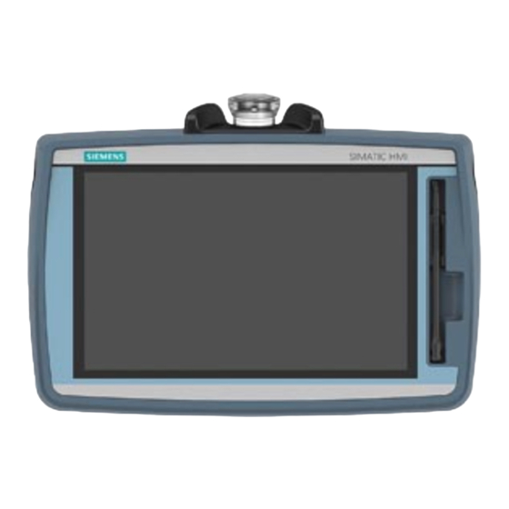
Overview Product overview The second generation of SIMATIC HMI Mobile Panels offers direct mobile operation and monitoring of the production process. The Mobile Panels 2nd Generation system consists of a Mobile Panel, connection box and connecting cable. The TP1000F Mobile RO has a 10" display in widescreen format. The figure below shows a fail-safe Mobile Panel connected to a connection box advanced. -
Page 12: Design Of The Mobile Panel
• At least one connection box (Page 15) • For hardwired F-systems: A safety relay (Page 20) You can find the ordering information for the system components on the Internet (https://mall.industry.siemens.com/mall/en/de/Catalog/Products/10165537). Front and side views The following figures show the design of the HMI device. - Page 13 Overview 1.2 Design of the Mobile Panel The position of the emergency stop button makes it easily accessible. Due to its profiled design, the emergency stop button is easily accessible. Two bumpers protect the emergency stop / stop button against impact damage, for example, if it falls. The bumpers are dimensioned so that the emergency stop / stop button can be activated during an impact.
-
Page 14: Ktp Mobile Connecting Cable
Overview 1.3 KTP Mobile connecting cable KTP Mobile connecting cable The connecting cable is resistant to many solvents and lubricants. The tensile and flexural strength of the connecting cable is geared toward the actual usage conditions. Functions of the connecting cable: ●... -
Page 15: Connection Boxes
Overview 1.4 Connection boxes Connection boxes The connection boxes are available in the following versions: ● Connection box compact, article number 6AV2125-2AE03-0AX0 ● Connection box standard, article number 6AV2125-2AE13-0AX0 ● Connection box advanced, article number 6AV2125-2AE23-0AX0 Connection box compact The figure below shows the connection box compact. ①... - Page 16 Overview 1.4 Connection boxes Connection box standard and connection box advanced The figure below shows the connection box standard or the connection box advanced. The connection box advanced also features: ● Real-time Ethernet ● F-signal transmission ① LED display ② Screw glands for the data cables ③...
- Page 17 ● LED flashes green or amber: Link established, data transfer in progress You can find information about other possible LED states in the following document: Operating instructions "SCALANCE X-200" (https://support.industry.siemens.com/cs/ww/en/view/102051962) See also Connecting the connection box (Page 50) TP1000F Mobile RO...
-
Page 18: Scope Of Delivery
Overview 1.5 Scope of delivery Scope of delivery This section describes the system components in the scope of delivery that you need for operating the HMI device. Mobile Panel 2nd Generation: ● TP1000F Mobile RO ● 1 DVD with documentation and product information ●... -
Page 19: Accessories
Overview Accessories are not included in the scope of delivery but can be ordered from the following address: SIMATIC HMI accessories (https://mall.industry.siemens.com/mall/en/de/Catalog/Products/10030052) In the Industry Mall you can find the following accessories: ● KTP Mobile wall-mounting bracket ● Memory card ●... -
Page 20: Usb Flash Drive
Panel. Use the following storage media: ● SIMATIC HMI Memory Card Siemens AG has approved the use of SD memory cards in the Mobile Panel. ● USB flash drive The USB flash drive must be suitable for industrial applications. The storage medium is inserted in the port on the left of the device. -
Page 21: The Remoteoperate Client Software
Overview 1.7 The HMI device in the operating process The HMI device in the operating process The HMI device is part of the operating process. The operating process is marked by three- way communication between the HMI device, server and PLC. The following figure shows an exemplary system design. -
Page 22: Terms For Fail-Safe Operation
You can find additional information on the topic of "Safety" in the following document: "SIMATIC Safety - Configuring and Programming" programming and operating manual (http://support.automation.siemens.com/WW/view/en/54110126) Fail-safe automation system, F system A fail-safe automation system is required in a plant with high safety requirements. An F- system is characterized by the following features: ●... - Page 23 Overview 1.9 Organizational measures Emergency stop, stop The operator presses the emergency stop / stop button to activate either an emergency stop or a stop. ● The emergency stop is an emergency action that is intended to stop a process or movement entailing danger.
-
Page 24: Organizational Measures
Overview 1.9 Organizational measures Organizational measures Measures If you are using a fail-safe Mobile Panel in a fail-safe system, you must consider the following organizational measures: ● Install stationary emergency stop or emergency off buttons in the plant that are effective independent of the Mobile Panel. -
Page 25: Safety Instructions
Safety instructions General safety instructions WARNING Personal injury or material damage due to non-compliance with safety regulations Failure to exactly comply with the safety regulations and procedures in this document can result in hazards and disable safety functions. This can result in personal injuries or material damage. - Page 26 This can result in personal injury or material damage. Take appropriate protection measures to prevent physical injury or material damage. You can find additional information in the following document:Configuration manual "SCALANCE X-200" (https://support.industry.siemens.com/cs/ww/de/view/109476763) TP1000F Mobile RO Operating Instructions, 08/2017, A5E39831415-AA...
- Page 27 Subscribe to the newsletter for fail-safe system components and the SIMATIC industrial software at the following link: Newsletter (https://www.industry.siemens.com/newsletter/public/AllNewsletters.aspx) To receive these newsletters, select the "News" check box. Safety during commissioning...
-
Page 28: Hmi Device
Safety instructions 2.1 General safety instructions Always adhere to the safety provisions applicable in the country of use. Strong high-frequency radiation NOTICE Observe immunity to RF radiation The device has an increased immunity to RF radiation according to the specifications on electromagnetic compatibility in the technical specifications. - Page 29 In order to protect plants, systems, machines and networks against cyber threats, it is necessary to implement – and continuously maintain – a holistic, state-of-the-art industrial security concept. Siemens’ products and solutions only form one element of such a concept. Customer is responsible to prevent unauthorized access to its plants, systems, machines and networks.
-
Page 30: Notes About Usage
Safety instructions 2.2 Notes about usage Notes about usage NOTICE HMI device approved for indoor use only The HMI device may be damaged if operated outdoors. Operate the HMI device indoors only. Note Using an Ethernet data transmission rate of 100 Mbps The Ethernet data transmission rate of 10 Mbps is not supported by Mobile Panels 2nd Generation. -
Page 31: Risk Analysis Of The Plant
Additional information on risk analysis and risk mitigation is available at: "Safety Technology in SIMATIC S7" system manual (http://support.automation.siemens.com/WW/view/en/12490443) Important information on emergency stop / stop button WARNING Emergency stop / stop button disabled when HMI device is not connected When the fail-safe Mobile Panel is not connected to the connection box, an emergency stop or stop cannot be triggered with the HMI device. - Page 32 Safety instructions 2.4 Important information on emergency stop / stop button WARNING Stop functions of Category 0 or 1 according to EN 60204-1 If a category 0 or 1 stop circuit is implemented, the stop function must be effective regardless of the operating mode. A category 0 stop must take precedence. Releasing the emergency stop / stop button must not lead to any dangerous state (see also EN 60204-1, Section 9.2.5.3).
-
Page 33: Important Notes For The Enabling Mechanism
Safety instructions 2.5 Important notes for the enabling mechanism Important notes for the enabling mechanism In a numerically controlled plant, "setup mode" requires an enabling mechanism. The enabling mechanism consists of the enabling button installed on the HMI device and the corresponding logic in the HMI device. - Page 34 Safety instructions 2.5 Important notes for the enabling mechanism NOTICE Enabling button must not be fixed Fixing the enabling button in one of its positions can cause malfunctions in the fail-safe automation system. Make sure that the enabling button is not being held permanently in any of its positions. Note The enabling button is effective when the HMI device is connected to a connection box.
-
Page 35: Control Cabinet
"Scope of delivery (Page 18)". Note Do not install parts damaged during shipment. In the case of damaged parts, contact your Siemens representative. See section "Service and support (Page 184)". Mounting the connection box compact 3.2.1 Mounting position, mounting cutout and clearance... - Page 36 Installing system components 3.2 Mounting the connection box compact The following illustration shows the dimensions for the mounting cut-out, all dimensions in Clearance The connection box is self-ventilated. To ensure self ventilation in the control cabinet and be able to connect the connecting cable without any problems, you need the clearance indicated in the figures below, all dimensions in mm: Note that in addition to the mounting depth of the connection box, a rear clearance is re-...
-
Page 37: Fastening The Connection Box Compact
Installing system components 3.3 Installing the connection box standard and connection box advanced 3.2.2 Fastening the connection box compact Read the instructions for work in and on electrical systems and on ESD in "General safety instructions (Page 25)". Requirement ● 4 mounting clips ●... -
Page 38: Fastening The Connection Box Standard And Connection Box Advanced
Installing system components 3.3 Installing the connection box standard and connection box advanced Clearance To ensure unhindered access to the interfaces, the clearance indicated in the figure below is required: 3.3.2 Fastening the connection box standard and connection box advanced This section describes the mounting of the Anschuss box standard and the connection box advanced on a flat metal surface, such as a control cabinet wall. -
Page 39: Attaching The Ktp Mobile Wall-Mounting Bracket
Installing system components 3.4 Attaching the KTP Mobile wall-mounting bracket Attaching the KTP Mobile wall-mounting bracket 3.4.1 Assembling the KTP Mobile wall-mounting bracket The scope of supply for the wall-mounting bracket includes the following components: ● Wall-mounting bracket ● Safety bar for the HMI device ●... -
Page 40: Mounting Position And Clearance
Installing system components 3.4 Attaching the KTP Mobile wall-mounting bracket 3.4.2 Mounting position and clearance Mounting position The KTP Mobile wall-mounting bracket is designed for vertical walls or one of the following types of enclosures: ● Mounting cabinets ● Control cabinets ●... - Page 41 Installing system components 3.4 Attaching the KTP Mobile wall-mounting bracket Clearance Consider the space required for the connecting cable used and the height that the HMI device extends up and over the wall-mounting bracket. The figure below shows the minimum clearance required around the wall bracket. TP1000F Mobile RO Operating Instructions, 08/2017, A5E39831415-AA...
-
Page 42: Fasteneing The Ktp Mobile Wall-Mounting Bracket
Installing system components 3.4 Attaching the KTP Mobile wall-mounting bracket 3.4.3 Fasteneing the KTP Mobile wall-mounting bracket Requirement The requirements refer to the installation of the wall-mounting bracket to a control cabinet. ● A level bolting surface ● 3 M5 bolts and a suitable screwdriver ●... -
Page 43: Sd Memory Card
Installing system components 3.5 Connecting the Mobile Panel Connecting the Mobile Panel 3.5.1 Connection information The Mobile Panel is supplied with an open terminal compartment. During commissioning, you will be working with an open terminal compartment when replacing the SD card or when replacing the connecting cable. - Page 44 Installing system components 3.5 Connecting the Mobile Panel Note Use only a SIMATIC HMI Memory Card Use only a SIMATIC HMI Memory Card with the Mobile Panel. NOTICE Unsuitable tools may damage the Mobile Panel To avoid damaging the motherboard of the Mobile Panel, insert or remove the SD memory card with an appropriate tool made of plastic.
-
Page 45: Connecting The Mobile Panel Connecting Cable
Installing system components 3.5 Connecting the Mobile Panel 3.5.3 Connecting the Mobile Panel connecting cable The connecting cable is a system component and is required for the operation of the Mobile Panel. Use a cable labeled "Connecting cable KTP Mobile". Note If you use an SD memory card, you must insert the SD memory card before installing the connecting cable. -
Page 46: Connecting Pc And Server
Installing system components 3.5 Connecting the Mobile Panel 3.5.4 Connecting PC and server When you update the operating system on the HMI device or want to reset the HMI device to factory settings, you have the transfer the image once again to the HMI device. Procedure 1. -
Page 47: Replacing The Connecting Cable
Installing system components 3.5 Connecting the Mobile Panel 3.5.5 Replacing the connecting cable Requirement ● The connecting cable is unplugged from the connection box. ● You have taken precautions to protect your device, see section "Connection information (Page 43)". ● Phillips screwdriver, size 2 Procedure Open 1. -
Page 48: Replacing An Sd Memory Card
Installing system components 3.5 Connecting the Mobile Panel 6. Plug the connector into port X80. Note the mechanical coding on the connector. 7. Plug in the RJ45 connector at port X1. Make sure that the connector audibly engages. 8. Place the terminal compartment cover over the terminal compartment. Tighten the corresponding screws using a torque of 0.2 Nm. -
Page 49: Inserting The Usb Memory Stick
Installing system components 3.5 Connecting the Mobile Panel Procedure Removing the SD memory card 1. Grab the SD memory card with an appropriate tool. 2. Pull the SD memory card from the slot to the center of the terminal compartment. Inserting a new SD memory card 1. -
Page 50: Connecting The Connection Box
Use shielded standard cables for all remaining data cables. You can find information on standard cables and additional information at: Industry Mall (https://mall.industry.siemens.com) NOTICE Foreign objects or liquids Foreign objects or liquids can cause a short-circuit inside the connection box and damage the connection box or HMI device accordingly. -
Page 51: Opening And Closing Connection Box Standard And Connection Box Advanced
Installing system components 3.6 Connecting the connection box 3.6.2 Opening and closing connection box standard and connection box advanced The connection boxes standard and advanced must be opened for connecting and setting the box ID. To avoid damage to the connection box, read the information in the section "General safety instructions (Page 25)"... - Page 52 Installing system components 3.6 Connecting the connection box 3. Remove the screws and the cover. The following protective cover is visible: ① Protective cover NOTICE Damage to the connection box Without a protective cover, there is a risk that the electronics of the connection box are damaged or destroyed.
-
Page 53: Equipotential Bonding Of Connection Boxes
"Directives for interference-free installation of programmable logic controllers (http://support.automation.siemens.com/WW/view/de/1064706)". ● Use equipotential bonding conductors made of copper or galvanized steel. Connect the equipotential bonding conductors to the ground / protective conductor over a wide area. - Page 54 Installing system components 3.6 Connecting the connection box ① Ground connection ② Equipotential bonding conductor, cross-section 1.5 mm ③ Equipotential busbar ④ PROFINET cable ⑤ Equipotential bonding conductor, cross-section ≥ 16 mm ⑥ Parallel routing of the equipotential bonding conductor and data cable ⑦...
-
Page 55: Connecting The Functional Grounding And Power Supply To The Connection Box
An external protective circuit is required for operation with 24 V DC; please refer to section 7 "Lightning protection and overvoltage protection" in the following function manual: "Designing interference-free SIMATIC S7-1500, ET 200MP, ET 200SP, ET 200AL controllers (https://support.industry.siemens.com/cs/ww/en/view/59193566)". Requirement ● The power supply meets the requirements set out in "Technical specifications (Page 165)". -
Page 56: Applies To
Installing system components 3.6 Connecting the connection box 3. Insert the wire ends into the corresponding spring-loaded terminal as shown in the figures below. The figure below shows the contacts to be connected to the X10 terminal of the connection box. ①... -
Page 57: Connecting Cables For A Hardwired F-System
Installing system components 3.6 Connecting the connection box 3.6.5 Connecting cables for a hardwired F-system The signals for the emergency stop / stop button and the enabling button must be wired for a hardwired F-system. NOTICE Length of the data cables to the connection box If the permissible length of the data cables and signal cables between a connection box and the plant is exceeded, malfunctions may occur. -
Page 58: Connecting Ethernet To The Connection Box
• Only use a switch or comparable device to connect the connection box to public Ethernet networks. • Follow the information in the "SIMATIC PROFINET system description (https://support.industry.siemens.com/cs/us/en/view/19292127)" manual for setting up a PROFINET network. TP1000F Mobile RO Operating Instructions, 08/2017, A5E39831415-AA... - Page 59 – 1 Ethernet cable (not preassembled) – 1 screwdriver, PZ 2 – 1 stripping tool See the online catalog at "Industry Mall (https://mall.industry.siemens.com)". Procedure Connection box compact 1. Plug the RJ45 connector on the Ethernet cable into the interface indicated.
- Page 60 Installing system components 3.6 Connecting the connection box Connection boxes standard and advanced 1. Strip the insulation on the Ethernet cable as shown in the figure below. 2. Open fast connector 1. ① Fast connector 1 ② Fast connector 2 ③...
-
Page 61: Setting The Box Id Of The Connection Box
Installing system components 3.6 Connecting the connection box 3.6.7 Setting the box ID of the connection box You need to set a box ID for each connection box. The box ID must be valid and is transferred to the RemoteOperate Server. The server can identify the client using the box ID. Note You need to set a box ID for each connection box. - Page 62 Installing system components 3.6 Connecting the connection box Requirement ● For connection box standard and connection box advanced: The connection box is open. ● The connection box is disconnected from its power supply. ● A suitable tool made of plastic Procedure 1.
-
Page 63: Secure Cables And Seal Screw Glands
Installing system components 3.6 Connecting the connection box 3.6.8 Secure cables and seal screw glands Once all cables are connected to the connection box, the following final steps should be carried out: ● Connection box compact: Strain relief for cables on the back of the connection box ●... -
Page 64: Connecting The Ktp Mobile Connecting Cable To The Connection Box
Installing system components 3.7 Connecting the KTP Mobile connecting cable to the connection box Connecting the KTP Mobile connecting cable to the connection box The connecting cable can be connected to the connection box using a circular connector. The connector is coded to prevent faulty insertion. The connecting cable is described in the section "KTP Mobile connecting cable (Page 14)". -
Page 65: Handling The Mobile Panel
Handling the Mobile Panel Holding the Mobile Panel and attaching it to the wall-mounting bracket Holding the HMI device The figure below shows the device being held on the forearm. When holding the Mobile Panel as shown, you can, for example, perform movements in the fail-safe automation system during setup mode. - Page 66 Handling the Mobile Panel 4.1 Holding the Mobile Panel and attaching it to the wall-mounting bracket Using the HMI device in a fixed position A wall-mounting bracket is available for securely fixing the HMI device in position. You can place the HMI in the wall-mounting bracket and operate it as a stationary device. Observe the necessary organizational measures as described in the section "Organizational measures (Page 24)".
-
Page 67: Operating The Enabling Button
Handling the Mobile Panel 4.2 Operating the enabling button Operating the enabling button The enabling mechanism comprises one integrated enabling button with three settings. The signals of the enabling button are evaluated internally and sent to the connection box over the connecting cable. For setup mode, these signals must be wired dual-channel from the connection box to the F-system. -
Page 68: Pressing The Emergency Stop / Stop Button
Handling the Mobile Panel 4.3 Pressing the emergency stop / stop button Pressing the emergency stop / stop button The emergency stop / stop button on the HMI device is an optional operator control. The emergency stop / stop button is designed with two circuits and enables a safety-related emergency stop or stop of the fail-safe automation system. - Page 69 Handling the Mobile Panel 4.3 Pressing the emergency stop / stop button Procedure Note Only press the emergency stop / stop button to avoid imminent danger. If you want to activate the emergency stop / stop button for test purposes, consult those responsible for the plant in advance.
-
Page 70: Testing Mobile Panel Readiness For Operation
Handling the Mobile Panel 4.4 Testing Mobile Panel readiness for operation Testing Mobile Panel readiness for operation This section describes how to check the operational readiness of the Mobile Panel after you have connected the connecting cable and, if necessary, a memory card to the Mobile Panel. Requirement ●... - Page 71 Handling the Mobile Panel 4.4 Testing Mobile Panel readiness for operation The RemoteOperate Client starts when the delay time comes to an end. The HMI device is ready for operation when the server selection list is displayed, see section "Using a client (Page 131)". TP1000F Mobile RO Operating Instructions, 08/2017, A5E39831415-AA...
- Page 72 Handling the Mobile Panel 4.4 Testing Mobile Panel readiness for operation Testing the enabling button and emergency stop / stop button function Note Before testing the enabling button and emergency stop / stop button functions, read the information in the following sections: •...
-
Page 73: Parameterizing The Mobile Panel
Parameterizing the Mobile Panel Desktop and Start Center Once the HMI device has been started, the display shows the Windows CE desktop. ① Desktop ② Start Center ③ Start menu ④ Icon for screen keyboard The Start Center The Start Center buttons have the following function: ●... -
Page 74: Operating The Desktop, Start Center And Control Panel
Parameterizing the Mobile Panel 5.2 Operating the desktop, Start Center and Control Panel Operating the desktop, Start Center and Control Panel You can operate the Windows user interface and the Start Center with the touch screen. The operator controls shown in the dialogs are touch-sensitive. Touch objects are operated in the same way as mechanical keys. -
Page 75: Security Mode
Parameterizing the Mobile Panel 5.4 Security mode Security mode 5.4.1 Overview You can protect the desktop icons, the taskbar and the "Settings" and "Taskbar" buttons in the Start Center from unauthorized access. Security mode prevents unauthorized access. Security mode can be activated if you have assigned a password as described in the section "Entering and deleting a password (Page 90)". -
Page 76: Control Panel
Parameterizing the Mobile Panel 5.5 Control Panel Procedure 1. Operate a password-protected desktop icon, the taskbar or the "Settings" or "Taskbar" button in the Start Center. The following dialog appears: 2. Enter the required password. 3. Confirm your entry with "OK". The dialog will close and the selected operator control open. -
Page 77: Overview Of Functions
Parameterizing the Mobile Panel 5.5 Control Panel 5.5.2 Overview of functions The table below shows the icons of the Control Panel and provides links to the corresponding function descriptions in the appropriate sections. Icon Functional description Importing, displaying and deleting certificates (Page 106) Setting the date and time (Page 89) Changing display brightness (Page 81) Configuring the screen keyboard (Page 82) -
Page 78: Operating The Control Panel
Parameterizing the Mobile Panel 5.5 Control Panel Icon Functional description Updating the HMI device image (ProSave) (Page 125) Using automatic backup (Page 127) Displaying general system properties (Page 99) Displaying memory distribution (Page 95) Specifying the computer name of the HMI device (Page 112) Configuring transfer (Page 94) Setting the delay time (Page 96) 5.5.3... -
Page 79: Display Types For The Screen Keyboard
Parameterizing the Mobile Panel 5.5 Control Panel 5.5.4 Display types for the screen keyboard The screen keyboard is used for entering alphanumeric, numeric and special characters. As soon as you touch a text box, a numeric or alphanumeric screen keyboard is displayed, depending on the type of the text box. - Page 80 Parameterizing the Mobile Panel 5.5 Control Panel Changing the display of the screen keyboard Function Switching between the numerical and alphanumerical keyboard Switching between the normal level and Shift level of the alphanumerical screen keyboard Switchover to special characters Switching from full display to reduced display Switching from reduced display to full display Closing of reduced display of the screen keyboard Brief touch: Hide screen keyboard...
-
Page 81: Configuring Operation
Parameterizing the Mobile Panel 5.6 Configuring operation Configuring operation 5.6.1 Changing display brightness You can use this function to change the brightness of the display by changing the intensity of the backlighting. The intensity of the backlighting can be adjusted with a slider or with the "Reduce brightness"... -
Page 82: Configuring The Screen Keyboard
Configuring the screen keyboard You can use this function to change the layout and the position of the screen keyboard. Requirement You have opened the "Siemens HMI Input Panel" dialog with the "InputPanel" icon. ① Check box for displaying the button in the screen keyboard ②... -
Page 83: Setting The Character Repeat Rate Of The Screen Keyboard
Parameterizing the Mobile Panel 5.6 Configuring operation 5.6.3 Setting the character repeat rate of the screen keyboard You can use this function to set the character repeat and repeat delay for the screen keyboard. Requirement The Control Panel is open. Procedure 1. -
Page 84: Setting The Double-Click
Parameterizing the Mobile Panel 5.6 Configuring operation 5.6.4 Setting the double-click You start applications in the Control Panel and in the operating system with a double-click. A double-click corresponds to two brief touches. In the "Mouse Properties" dialog, make the following settings for operation with the touch screen: ●... -
Page 85: Calibrating The Touch Screen
Parameterizing the Mobile Panel 5.6 Configuring operation 5.6.5 Calibrating the touch screen Parallax may occur on the touch screen depending on the mounting position and perspective. To prevent any resulting operating errors, you may need to calibrate the touch screen. Requirement ●... -
Page 86: Restarting The Hmi Device
Parameterizing the Mobile Panel 5.6 Configuring operation 4. Touch the center of the calibration cross until it is shown at the next position. The calibration cross appears at four other positions. Once you have touched the calibration cross at all positions, the following dialog appears: 5. - Page 87 Parameterizing the Mobile Panel 5.6 Configuring operation Requirement ● If you want to restore the factory settings: The HMI device is connected in accordance with "Connecting PC and server (Page 46)". ● You have opened the "Device" tab in the "OP Properties" dialog with the "OP" icon. Procedure 1.
-
Page 88: General Settings
Parameterizing the Mobile Panel 5.7 General settings General settings 5.7.1 Regional and language settings The date, time and decimal points are displayed differently in different countries. You can adapt the display format to meet the requirements of various regions. Requirement The Control Panel is open. -
Page 89: Setting The Date And Time
Parameterizing the Mobile Panel 5.7 General settings 5.7.2 Setting the date and time You can use this function to set the date and time. The HMI device has an internal buffered clock. Requirement The Control Panel is open. Procedure 1. Open the "Date/Time Properties" dialog using the "Date/Time" icon. ①... -
Page 90: Entering And Deleting A Password
Parameterizing the Mobile Panel 5.7 General settings The settings for the data and time of day have now been changed. The HMI device must be restarted after changes in the following cases: ● You have changed the time zone setting ●... - Page 91 Parameterizing the Mobile Panel 5.7 General settings Procedure Setting up password protection 1. Double-click on the "Password" icon. The following dialog appears: 2. Enter the password in the "Password" text box. Activate the numeric keyboard on the screen for this. 3.
-
Page 92: Setting The Screen Saver
Parameterizing the Mobile Panel 5.7 General settings 5.7.4 Setting the screen saver You can set the following time intervals in the Control Panel: ● Automatic activation of the screen saver ● Automatic reduction in the display backlighting The HMI device exhibits the following behavior based on the settings: ●... - Page 93 Parameterizing the Mobile Panel 5.7 General settings Procedure 1. Open the "Screensaver" dialog using the "ScreenSaver" icon. ① Period of time in minutes before the screen saver is activated ② Type of screen saver ③ Reduced backlighting to a specified value ④...
-
Page 94: Configuring Transfer
Parameterizing the Mobile Panel 5.7 General settings 5.7.5 Configuring transfer A HMI device image can only be transferred from the PC to the HMI device when at least one data channel is configured and enabled on the HMI device. Follow the procedure below to configure transfer mode. -
Page 95: Storage Management
Parameterizing the Mobile Panel 5.7 General settings 3. Select the required data channel in the "Transfer channel" group. – PN/IE Transfer is over PROFINET or Industrial Ethernet. This means an HMI device can communicate over a switch or over a router in the local network. –... -
Page 96: Setting The Delay Time
Parameterizing the Mobile Panel 5.7 General settings 5.7.6.2 Setting the delay time Introduction After switching on the HMI device, the RemoteOperate Client application starts after a delay time. Requirements You have opened the "Directories" tab in the "Transfer Settings" dialog with the "Transfer"... - Page 97 Parameterizing the Mobile Panel 5.7 General settings Procedure for setting the delay time 1. Select the desired delay time for the software start from the "Wait [sec]" selection box. The delay time sets how long the Start Center is displayed before the RemoteOperateClient software starts.
-
Page 98: Backing Up Registry Information And Temporary Data
Parameterizing the Mobile Panel 5.7 General settings 5.7.7 Backing up registry information and temporary data You can install and uninstall your own software on and from the HMI device. You need to back up the registry settings to flash memory after installation or removal. You can also save the data in the memory buffer to flash memory. -
Page 99: Displaying General System Properties
Displaying information about the Mobile Panel You can use this function to display device-specific information. You will need this information if you contact Technical Support (https://support.industry.siemens.com). Requirement You have opened the "Device" tab in the "OP Properties" dialog with the "OP" icon. -
Page 100: Display Firmware
Parameterizing the Mobile Panel 5.7 General settings ① HMI device name ② Version of the HMI device image ③ Version of the bootloader ④ Bootloader release date ⑤ Size of the internal flash memory in which the HMI device image and projects are stored ⑥... -
Page 101: Changing Internet Settings
Parameterizing the Mobile Panel 5.8 Changing Internet settings Changing Internet settings 5.8.1 Changing general settings You can use this function to set the homepage and search engine page for an Internet connection over Internet Explorer. Requirement ● You have opened the "General" tab in the "Internet Options" dialog with the "Internet Options"... -
Page 102: Setting The Proxy Server
Parameterizing the Mobile Panel 5.8 Changing Internet settings 5.8.2 Setting the proxy server Use this function to configure the type of Internet access. Requirement ● You have opened the "Connection" tab in the "Internet Options" dialog with the "Internet Options" icon. ①... -
Page 103: Changing Internet Security Settings
Parameterizing the Mobile Panel 5.8 Changing Internet settings 5.8.3 Changing Internet security settings A cookie typically contains information about websites visited; the Internet browser saves this information automatically when you surf the Internet. You can restrict cookies on a tab under "Internet Options". - Page 104 Parameterizing the Mobile Panel 5.8 Changing Internet settings 5. If server verification is required for all websites on the list of trusted sites, select the "Require server verification" check box. 6. To edit the settings for ActiveX control, plug-ins and script languages, select "Settings". The following dialog appears: 7.
-
Page 105: Activating Encryption Protocols
Parameterizing the Mobile Panel 5.8 Changing Internet settings 5.8.4 Activating encryption protocols Data can be encrypted for greater data transmission security. Common encryption protocols include SSL and TLS. TLS is a more advanced encryption protocol than SSL. You can activate or deactivate the usage of encryption protocols. Read "General safety instructions (Page 25)". -
Page 106: Importing, Displaying And Deleting Certificates
Parameterizing the Mobile Panel 5.8 Changing Internet settings 5.8.5 Importing, displaying and deleting certificates You can use this function to import, display and delete certificates. The certificates are proof of an IT qualification and the categories are as follows: ● Certificates that you can trust ●... - Page 107 Parameterizing the Mobile Panel 5.8 Changing Internet settings 4. Use the "Import.." button to specify the source from which the certificate will be imported. The following dialog appears: ① Import from a file ② Import from a smart card reader 5.
-
Page 108: Checking The Profinet Io Settings
Parameterizing the Mobile Panel 5.9 Checking the PROFINET IO settings 9. You can use the "Remove" button to delete a certificate. Note The entry is deleted immediately and without further inquiry. If you want to again use a deleted certificate, you need to import it again from a storage medium. 10. -
Page 109: Server Time
Parameterizing the Mobile Panel 5.10 Server time 5.10 Server time To obtain the time of the HMI device from a time server, you can specify up to four different time servers. The time is synchronized using the "Network Time Protocol". The synchronization cycle applies to all configured time servers. - Page 110 Parameterizing the Mobile Panel 5.10 Server time 6. Enter the DNS name of the time server under "Name". You can also enter the IP address of the time server. 7. Use the "Test" button to check the accessibility of the time server. The communication connection to the time server is established and the time is displayed in the "DateTime:"...
-
Page 111: Configuring Network Operation
Parameterizing the Mobile Panel 5.11 Configuring network operation 5.11 Configuring network operation 5.11.1 Overview Addressing computers Computers are usually addressed using computer names within a PROFINET network. However, the network address is set with RemoteOperate. Determine the following parameters: ● Is DHCP used in the local network for dynamic assignment of addresses? If not, get a TCP/IP address for the HMI device. -
Page 112: Specifying The Computer Name Of The Hmi Device
Parameterizing the Mobile Panel 5.11 Configuring network operation 5.11.2 Specifying the computer name of the HMI device You can use this function to assign a computer name to the HMI device. The computer name is used to identify the HMI device in the local network. Requirement The Control Panel is open. -
Page 113: Specifying The Ip Address And Name Server
Parameterizing the Mobile Panel 5.11 Configuring network operation 5.11.3 Specifying the IP address and name server You can use this function to address the HMI device in the local network. Requirement ● You have opened the following window with the "Network and Dial-up Connections" icon: ●... -
Page 114: Specifying The Logon Data
Parameterizing the Mobile Panel 5.11 Configuring network operation 5. If a name server is used in the local network, open the "Name Servers" tab. The following dialog appears: 6. Enter the respective addresses in the text boxes. 7. Confirm your entries. The dialog closes. -
Page 115: Assigning A Safety-Related Operating Mode
Parameterizing the Mobile Panel 5.12 Assigning a safety-related operating mode 5.12 Assigning a safety-related operating mode This section describes how to assign failsafe mode to a connection box. You specify the function of the emergency stop/stop button for each connection box by selecting the operating mode: ●... - Page 116 Parameterizing the Mobile Panel 5.12 Assigning a safety-related operating mode Requirement ● The HMI device is connected to the connection box. ● The box ID has been set as described in "Setting the box ID of the connection box (Page 61)". ●...
-
Page 117: Functions For Service And Commissioning
Parameterizing the Mobile Panel 5.13 Functions for service and commissioning 3. Confirm your entries with "Save". Note For the "E-stop button evaluated by safety relay" operating mode: • If password protection is already enabled, the password prompt is displayed. • If no password has been assigned, you are prompted to assign a password. Enter the password and confirm your entry. - Page 118 Parameterizing the Mobile Panel 5.13 Functions for service and commissioning Requirement ● You have opened the "Backup" tab in the "Service & Commissioning" dialog with the "Service & Commissioning" icon. ① Data that can be saved ● There is a storage medium with sufficient free capacity in the HMI device. ●...
- Page 119 Parameterizing the Mobile Panel 5.13 Functions for service and commissioning 4. Select "Next". The following dialog appears: ① List of available backup files ② Progress bar during data backup 5. If you only want to backup compatible files, select the "compatible files only" check box. –...
-
Page 120: Restoring From External Storage Medium - Restore
Parameterizing the Mobile Panel 5.13 Functions for service and commissioning See also Storage media (Page 20) Restoring from external storage medium – Restore (Page 120) 5.13.2 Restoring from external storage medium – Restore Use this function to restore data from a storage medium to the HMI device. A restore operation deletes the old data from flash memory of the HMI device on confirmation. - Page 121 Parameterizing the Mobile Panel 5.13 Functions for service and commissioning Procedure 1. Select "Next". The Restore from external memory dialog is displayed. The dialog corresponds to the "Backup to external memory" dialog in the section "Saving to external storage medium – backup (Page 117)".
- Page 122 Parameterizing the Mobile Panel 5.13 Functions for service and commissioning 7. To delete the file selected, press "Delete". The Delete confirmation dialog is displayed. The file is deleted when you select "OK". 8. To restore the data from the selected file, select "Restore". The following dialog appears: 9.
-
Page 123: Backing Up And Restoring Data (Prosave)
Parameterizing the Mobile Panel 5.13 Functions for service and commissioning 5.13.3 Backing up and restoring data (ProSave) Requirements ● The HMI device is connected to a PC by means of the connection box and Ethernet. ● The ProSave application is installed on the PC. The ProSave software is located on the "SIMATIC RemoteOperate - Applications &... - Page 124 Parameterizing the Mobile Panel 5.13 Functions for service and commissioning Procedure for restoring NOTICE Data loss All data on the HMI device is deleted during a restore operation. Back up your data before the restore operation, if necessary. Proceed as follows: 1.
-
Page 125: Updating The Hmi Device Image (Prosave)
Parameterizing the Mobile Panel 5.13 Functions for service and commissioning 5.13.4 Updating the HMI device image (ProSave) The following applications are pre-installed on the HMI device: ● The Microsoft Windows Embedded Compact 2013 operating system. ● The RemoteOperate Client software The "SIMATIC RemoteOperate - Applications &... - Page 126 Parameterizing the Mobile Panel 5.13 Functions for service and commissioning 9. To restore the delivery state of the HMI device and set all device parameters to their default values, enable "Reset to factory settings". 10. In the "Start Center" of the HMI device, click on the "Transfer" button. 11.
-
Page 127: Using Automatic Backup
Parameterizing the Mobile Panel 5.13 Functions for service and commissioning 5.13.5 Using automatic backup If the "Automatic Backup" function is enabled, the HMI device stores all data required for operation on the system memory card. You can insert the system memory card into any HMI device of the same type. - Page 128 Parameterizing the Mobile Panel 5.13 Functions for service and commissioning If the "Automatic Backup" function is currently disabled ("Enabled: No"), the "Enable & Reboot" button is displayed. 3. Press the "Disable & Reboot" or "Enable &Reboot" button to disable or enable the automatic backup.
- Page 129 Parameterizing the Mobile Panel 5.13 Functions for service and commissioning Using the system memory card without automatically backed up data 1. In the "Service & Commissioning" dialog, "Automatic Backup" tab, check whether the "Automatic Backup" function is enabled. – If the function is enabled, close the dialog. –...
- Page 130 Parameterizing the Mobile Panel 5.13 Functions for service and commissioning Using system memory card with automatic backup, project data on the device NOTICE Data loss All data on the HMI device, including the project and HMI device password, is deleted during a restore operation.
-
Page 131: Using A Client
Using a client Creating/editing a server selection list When you switch on the HMI device and once the HMI device starts up, the server selection list is displayed in the "Client - RemoteOperate" dialog box: Note When you switch on the HMI device for the first time, the server selection list is empty. You must first create a new server. - Page 132 Using a client 6.1 Creating/editing a server selection list Create a new server connection Note Limited number of servers per client RemoteOperate supports a maximum of ten servers in a client's server selection list. If you wish to create a new server, make sure that there are no more than nine servers in the server selection list.
- Page 133 Using a client 6.1 Creating/editing a server selection list 2. In the "tree path" box, enter the path to the server within the server selection list. The "Path" specifies the node in the server tree under which the server connection is created. For example, if you specify "\Area1\", the IP address of the server will subsequently appear under the "Area1"...
- Page 134 Using a client 6.1 Creating/editing a server selection list Changing the properties of a server connection Proceed as follows: 1. Select the server whose properties you wish to edit. 2. With the button, open the dialog box to change the server properties. 3.
-
Page 135: Connect Client
Using a client 6.2 Connect client Connect client Requirement ● You have switched on the HMI device. Note If you have switched on the HMI device for the first time, the server selection list is empty. Create a new server selection list. Procedure 1. - Page 136 Using a client 6.2 Connect client Note Response to a network fault If a transient or long-term network fault occurs, the client repeatedly tries to establish a connection to the server. You can abort this repeated attempt to establish a connection with the button.
- Page 137 Using a client 6.2 Connect client The operator authorization window ("traffic lights") The operator authorization window, known as "traffic lights", is displayed in the foreground on the server screen and the screens of all connected clients with operator authorization. The traffic lights can assume the following states: Traffic light icon Activated by Meaning...
- Page 138 Using a client 6.2 Connect client Note The length of time you need to press the touch screen before the RemoteOperate toolbar is displayed is defined in the "roServer.ini" file. The special functions of the RemoteOperate toolbar are shown in the table below: Buttons Functions Executes a right-click on the server.
-
Page 139: Closing The Remoteoperate Client
Using a client 6.3 Closing the RemoteOperate Client Closing the RemoteOperate Client Procedure Proceed as follows: If you are still connected to a server, close the connection as follows: 1. Press the touch screen until the RemoteOperate toolbar is displayed: Alternatively, you can click once on the traffic lights. - Page 140 Using a client 6.3 Closing the RemoteOperate Client Result You have closed the RemoteOperate Client software. The Start Center is displayed: The Start Center contains the following four buttons: ● Use the "Transfer" button to transfer data from a PC to the HMI device. ●...
-
Page 141: Changing The Server
Using a client 6.4 Changing the server Changing the server Requirements ● The HMI device is connected as a client to a server. Procedure Proceed as follows: 1. Press the touch screen until the RemoteOperate toolbar is displayed. If you have operator authorization you can, as an alternative, click the traffic lights. Note Setting the time to display the toolbar The length of time you need to press the touch screen before the RemoteOperate toolbar... -
Page 142: Example: Assigning Operator Authorization
Using a client 6.5 Example: Assigning operator authorization Example: Assigning operator authorization Introduction This chapter describes how to assign operator authorization on the server to different clients in succession. The description uses an example configuration with one server and three HMI devices connected to the server as clients via Ethernet. - Page 143 Using a client 6.5 Example: Assigning operator authorization ● Client 1, client 2, and client 3 connect to the server. All clients can see the project that is running on the server on their screen. If neither client executes an operation, all traffic lights are green at first: Client 1 Client 2 Client 3...
- Page 144 Using a client 6.5 Example: Assigning operator authorization ● A user tries to operate on client 2. The operator request dialog opens on the screens of client 1, client 2, client 3 as well as the server screen: ● Since the user on client 1 has operator authorization, he decides on whether to transfer operator authorization: –...
- Page 145 Using a client 6.5 Example: Assigning operator authorization ● The operator at client 1 disables the "Forced Exclusive" mode, for example by pressing the switch close to the HMI device. If the operator at client 1 continues operation, the traffic light will stay green while all other traffic lights will turn red: Client 1 Client 2...
-
Page 146: Alarm Window
Using a client 6.6 Alarm window Alarm window Overview RemoteOperate displays new alarms: ● Serious errors in the popup window (see figure below) ● Alarm messages in the alarm window (see section "Opening and closing alarm windows") TP1000F Mobile RO Operating Instructions, 08/2017, A5E39831415-AA... - Page 147 Using a client 6.6 Alarm window Opening and closing the alarm window As soon as a new Alarm message is pending, the alarm window opens and the pending alarms are shown (see section "Pending alarms" below). TP1000F Mobile RO Operating Instructions, 08/2017, A5E39831415-AA...
- Page 148 Using a client 6.6 Alarm window 1. Close the alarm window. If no Alarm message is pending, the "Alarm window" button is grayed out and disabled (see section "Create/edit server selection list"). If an Alarm message is still pending, the "Alarm window" button is active. 2.
-
Page 149: Fail-Safe Operation
Fail-safe operation Connecting the connecting cable Requirement ● The Mobile Panel is ready for operation. Procedure Connecting to a connection box without an assigned operating mode Note If the connection box has not yet been assigned an operating mode, the emergency stop / stop button does not light up when the connecting cable is plugged in. -
Page 150: Unplugging The Connecting Cable
Fail-safe operation 7.2 Unplugging the connecting cable Unplugging the connecting cable Procedure NOTICE Connection box compact and connection box standard When unplugging the connecting cable from the connection box compact or a connection box standard, there is no automatic bypass of the emergency stop / stop circuit. Without further actions, an emergency stop or stop is triggered in the plant and the plant switches to a safe state. -
Page 151: Maintenance And Care
Maintenance and care Replacing the Mobile Panel When replacing an HMI device, the following applies: ● The TP1000F Mobile RO can only be replaced with a device of the same design. ● For a 1:1 data transfer from one HMI device to another, a replacement device with identical construction is required. -
Page 152: Maintaining The Mobile Panel
Maintenance and care 8.3 Maintaining the Mobile Panel Performing function tests Function test of enabling button 1. Connect the HMI device to a connection box. 2. Press the enabling button to switch position 2 "Enabling". 3. Check whether the plant reacts to the "Enabling" switch position as defined. 4. -
Page 153: Replacing The Touch Pen
Maintenance and care 8.4 Replacing the touch pen Procedure NOTICE Damage to the HMI device caused by unsuitable cleaning agents The use of steam cleaners, high pressure cleaners, compressed air, solvents or abrasive cleaners will damage the HMI device. Use a cleaning cloth dampened with a cleaning agent to clean the equipment. Only use water with a little liquid soap or a screen cleaning foam. -
Page 154: Spare Parts And Repairs
8.5 Spare parts and repairs Spare parts and repairs If the HMI device needs to be repaired, ship it to the Return Center in Erlangen. The address is: Siemens AG Digital Factory Retouren-Center c/o Geis Service GmbH, Tor 1-4 Kraftwerkstraße 25a... -
Page 155: Technical Specifications
● The following also applies for fail-safe Mobile Panels: 2006/42/EC "Machinery Directive" EC Declaration of Conformity The EC Declaration of Conformity is available to the relevant authorities at the following address: Siemens AG Digital Factory Factory Automation DF FA AS DH AMB... -
Page 156: Standards On Operating Safety
Technical specifications 9.2 Standards on operating safety Marking for Australia The HMI device and the connection boxes satisfy the requirements of Standard AS/NZS CISPR 16. Identification for Eurasion Customs Union ● EAC (Eurasian Conformity) ● Customs union of Russia, Belarus and Kazakhstan ●... -
Page 157: Electromagnetic Compatibility
EMC-compliant use of the Mobile Panel and connection box and the use of interference- proof cables are prerequisites for error-free operation. Note the following manuals: ● Directives for interference-free installation of programmable logic controllers (http://support.automation.siemens.com/WW/view/de/1064706), German ● Designing interference-free SIMATIC S7-1500, ET 200MP, ET 200SP, ET 200AL controllers (https://support.industry.siemens.com/cs/ww/en/view/59193566) - Page 158 Technical specifications 9.3 Electromagnetic compatibility Disturbance variables Electromagnetic compatibility applies for the following types of disturbance variables: ● Pulse-shaped disturbance variables The table below shows the electromagnetic compatibility of the Mobile Panel and the connection boxes with regard to pulse-shaped disturbance variables. Pulse-shaped disturbance Tested with Degree of...
-
Page 159: Emitted Interference
Technical specifications 9.4 Mechanical ambient conditions 9.3.2 Emitted interference The HMI device meets the requirements of EN 61000-6-4. The HMI device complies with limit class A. The connection boxes meet the requirements of EN 61000-6-4. The HMI device complies with limit class A. Note The HMI device and connection boxes are not designed for use in residential areas. -
Page 160: Climatic Ambient Conditions
Technical specifications 9.5 Climatic ambient conditions Climatic ambient conditions 9.5.1 Transport and storage conditions The following information applies to an HMI device and connection box transported and stored in their original packaging. The HMI device meets the requirements of IEC 60721-3-2, Class 2K2 with the following amendments and limitations: Type of condition Permitted range... -
Page 161: Dimension Drawings
Technical specifications 9.6 Dimension drawings Dimension drawings 9.6.1 TP1000F Mobile RO dimension drawing All dimensions in mm TP1000F Mobile RO Operating Instructions, 08/2017, A5E39831415-AA... -
Page 162: Connection Box Compact Dimension Drawing
Technical specifications 9.6 Dimension drawings 9.6.2 Connection box compact dimension drawing TP1000F Mobile RO Operating Instructions, 08/2017, A5E39831415-AA... -
Page 163: Dimension Drawing For Connection Box Standard And Connection Box Advanced
Technical specifications 9.6 Dimension drawings 9.6.3 Dimension drawing for connection box standard and connection box advanced TP1000F Mobile RO Operating Instructions, 08/2017, A5E39831415-AA... -
Page 164: Ktp Mobile Wall-Mounting Bracket Dimension Drawing
Technical specifications 9.6 Dimension drawings 9.6.4 KTP Mobile wall-mounting bracket dimension drawing TP1000F Mobile RO Operating Instructions, 08/2017, A5E39831415-AA... -
Page 165: Technical Specifications
Technical specifications 9.7 Technical specifications Technical specifications 9.7.1 Mobile Panel Mechanical system TP1000F Mobile RO Weight without packaging Approx. 1650 g Height of fall 1.2 m Weight of the KTP Mobile wall-mounting bracket without packaging Approx. 1000 g Display TP1000F Mobile RO Type LCD TFT Active display area... - Page 166 Technical specifications 9.7 Technical specifications Interfaces TP1000F Mobile RO 1 × Ethernet RJ45 10/100 Mbps USB 2.0 Power supply, via connection box TP1000F Mobile RO Rated voltage +24 V DC Permitted voltage range 19.2 … 28.8 V (24 V ± 20%) Transients, maximum permitted 35 V (500 ms) Time between two transients...
-
Page 167: Connection Box Compact Connection Box Standard Connection Box Advanced
Overvoltage category 9.7.2 Connecting cable Weight You can find the information based on length on the Internet at: SIMATIC HMI accessories (https://mall.industry.siemens.com/mall/en/de/Catalog/Products/10030052) * Bending radius, ≥ 4-times the outside diameter of the line minimum Rated condition, 0 to 55 °C... - Page 168 Technical specifications 9.7 Technical specifications Power supply The information in the table below applies to all connections boxes. Rated voltage +24 V DC Permitted voltage range 19.2 … 28.8 V (± 20 %) Transients, maximum permitted 35 V (500 ms) Time between two transients ≥...
- Page 169 9.7 Technical specifications A detailed description of the internal SCALANCE switches of both connection boxes is available in the following documents: ● Operating instructions "SCALANCE X-200" (https://support.industry.siemens.com/cs/ww/en/view/102051962) ● Configuration manual "SCALANCE X-200" (https://support.industry.siemens.com/cs/ww/de/view/109476763) Insulation testing, protection class and degree of protection...
-
Page 170: Power Consumption Specifications
Technical specifications 9.7 Technical specifications 9.7.4 Power consumption specifications The connection box and Mobile Panel must be taken into consideration when calculating the power consumption. The tables below show typical values for the power consumption. Note The actual power consumption may vary depending on the configuration and the load at the interfaces of the Mobile Panel deviating from the specified values. - Page 171 Technical specifications 9.7 Technical specifications Reaction times The table shows below the reaction times of the HMI device up to the output or interface X10 of the connection box, dependent on the F-system. Operating mode Stop/E-stop button evaluated by safety relay Reaction time Emergency stop / stop button Reaction time during error-free...
- Page 172 Technical specifications 9.7 Technical specifications Safety characteristics for the HMI devices and the associated connection boxes ● In accordance with IEC 61508 Maximal attainable safety integrity level SIL2 (Proof Test Interval 1 year) SIL3 (Proof Test Interval 1 month) Mode of operation High and low demand mode Hardware fault tolerance (HFT) Classification...
-
Page 173: Specification Of Cables To Be Used
Connectable cable 6XV1840-2AH10 or comparable 6XV1840-2AH10 or comparable, Industrial Ethernet FastConnect Cable 2x2 * Connection technology Fast connect RJ45 * Available on the Internet at: Industrial Ethernet FastConnect Cable 2x2 (http://w3.siemens.com/mcms/industrial-communication/en/ie/Cabling-technology/fc-cable- 2x2/Pages/fc-cable-2x2.aspx) TP1000F Mobile RO Operating Instructions, 08/2017, A5E39831415-AA... -
Page 174: Interface Description For Mobile Panel
Technical specifications 9.8 Interface description for Mobile Panel Interface description for Mobile Panel 9.8.1 Internal interface X1 P1 RJ45 plug connector, socket, 8-pin Contact Assignment TD– Not connected Not connected RD– Not connected Not connected 9.8.2 Internal interface X80 Pin connector, 12-pole The pin connector has connections for: ●... -
Page 175: Connection Box Compact Interfaces
Technical specifications 9.9 Connection box compact interfaces Connection box compact interfaces 9.9.1 Position of the interfaces The figure below shows the interfaces of the connection box compact with relevance for commissioning. ① Interface X1 ② Interface X10 9.9.2 Interface X1 RJ45 socket, 8-pin Contact Assignment... -
Page 176: Plug-In Terminal Strip X10
Technical specifications 9.9 Connection box compact interfaces 9.9.3 Plug-in terminal strip X10 Plug-in terminal strip, 12-pin Contact Assignment Associated circuits and reference information Functional grounding Ground and power supply See "Connecting the functional grounding and power supply to the connection box (Page 55)." Not connected ENABLE2–... -
Page 177: Enabling Button
Technical specifications 9.9 Connection box compact interfaces Enabling button The figure below shows the wiring of the enabling button in the connection box compact. TP1000F Mobile RO Operating Instructions, 08/2017, A5E39831415-AA... -
Page 178: Interfaces Of The Connection Box Standard And Connection Box Advanced
Technical specifications 9.10 Interfaces of the connection box standard and connection box advanced 9.10 Interfaces of the connection box standard and connection box advanced 9.10.1 Position of the interfaces The figure below shows the position of the interfaces in the connection box standard and in the connection box advanced with relevance for commissioning. -
Page 179: Emergency Stop / Stop Button
Technical specifications 9.10 Interfaces of the connection box standard and connection box advanced 9.10.2 Fast connector X1 and X2 Fast Connector, 4-pin The connection box contains two fast connectors for connecting the Ethernet data cables. Contact Color Assignment in the connection box Assignment in the PLC Yellow White... -
Page 180: Wiring Of Safety-Related Operator Controls
Technical specifications 9.10 Interfaces of the connection box standard and connection box advanced 9.10.4 Wiring of safety-related operator controls Emergency stop/stop button Connection box standard The figure below shows the wiring of the emergency stop/stop button in the connection box standard. - Page 181 Technical specifications 9.10 Interfaces of the connection box standard and connection box advanced Connection box advanced The figure below shows the wiring of the emergency stop/stop button in the connection box advanced. The stop bypass only works if the connection box is supplied with power. TP1000F Mobile RO Operating Instructions, 08/2017, A5E39831415-AA...
- Page 182 Technical specifications 9.10 Interfaces of the connection box standard and connection box advanced Enabling button The figure below shows the wiring of the enabling button in the connection box standard and in the connection box advanced. TP1000F Mobile RO Operating Instructions, 08/2017, A5E39831415-AA...
-
Page 183: Technical Support
If an internal error occurs in the HMI device, the HMI device displays a message. Safety functions are no longer available. If the error persists after resetting the fail-safe module, contact the Siemens hotline. You can find additional information in the following section: Service and support (Page 184) ●... -
Page 184: Service And Support
For support information, refer to "Displaying information about the Mobile Panel (Page 99)" and "Display firmware (Page 100)". ● Support request form (http://www.siemens.com/automation/support-request) ● After-sales information system for SIMATIC PC/PG (http://www.siemens.com/asis) ● Overall SIMATIC documentation (http://www.siemens.com/simatic-tech-doku-portal) ● Contacts and office locations (http://www.automation.siemens.com/mcms/aspa-db/en/Pages/default.aspx) -
Page 185: List Of Abbreviations
List of abbreviations List of abbreviations Australian Standard American Wire Gauge Central Processing Unit Canadian Standards Association Data block Direct Current DHCP Dynamic Host Configuration Protocol Domain Name System Distributed I/O Digital Versatile Disk Input and Output Eurasian Conformity European Community Electrostatically sensitive devices Electromagnetic compatibility European standard... - Page 186 List of abbreviations B.1 List of abbreviations New Zealand Standard Organization block Operator Panel Personal Computer Programming device PELV Protective Extra Low Voltage Random Access Memory RJ45 Registered Jack Type 45 RemoteOperate Secure Digital SELV Safety Extra Low Voltage SMTP Simple Mail Transfer Protocol Service Packet Secure Socket Layer...
-
Page 187: Glossary
Glossary "Automatic mode" and "setup mode" Program-controlled plants pose a significant safety risk for operators. EN 12417 "Machine tools. Safety. Machining centers" and DIN EN 13128 " Safety of machine tools - Milling and boring machines" define operating modes to ensure staff safety. A "setup mode" is required for correct plant setup for "automatic mode". - Page 188 Glossary PROFINET Within the framework of Totally Integrated Automation, PROFINET represents the systematic further development of the following bus systems: ● PROFIBUS DP as well-established fieldbus ● Industrial Ethernet as the communications bus for the cell level The experience gained from both systems has been and continues to be integrated in PROFINET.
-
Page 189: Index
Index Accessories Calibrating Accessory kit, 18 Touch screen, 85 Accessory kit, 18 Care Activate HMI device, 153 Security mode, 76 Address assignment Applications & Documentation, 18 TCP/IP network, 113 CE approval, 155 Approval, 155, (EAC) Certificate, 155 Australia, 156 Certificates Stores, 106 CE, 155 Changing Automatic Backup, 127... - Page 190 Index Connect Client to a server, 135 Data channel Connecting Enabling, 94 Configuration PC, 46, 59 Locking, 94 Connecting cable, 64 Parameter assignment, 94 Equipotential bonding, 53 Date Connecting cable Setting, 89 Connecting, 64 Date format, 88 Design, 14 Date/time properties, 89 Unplugging, 64, 150 Deactivating Connection box...
- Page 191 Index Emergency stop, 23 Emergency stop / stop button High-frequency radiation, 28 Function test, 152 HMI device, 5 Emergency stop / stop bypass, 23 Care, 153 Emergency stop button Displaying information, 99 Operating, 69 Front view, 12 Emission, 30, 158 Function test, 70 Enabling Holding, 65...
- Page 192 Index Internet Browser, 74 Name server, 114 Explorer, 74 Network Homepage, 101 Response to a fault, 136 Internet browser, 101 Network fault, 136 Internet options Network ID, 114 Advanced, 103 Network operation Connection, 102 Computer name, 112 General, 101 Network parameters Privacy, 103, 105 Setting, 113 IP address...
- Page 193 Index Removing Password, 91 Panic activation Server from server selection list, 134 Enabling button, 67 Replugging Parameter assignment Mobile Panel, 150 Data channel, 94 Restart, 87 Operating system, 73 Restoring, 124 Password From external storage device, 120 Removing, 91 With ProSave, 124 Setting up, 91 Risk analysis, 31 Password properties, 90...
- Page 194 Index Server Storage medium Changing, 141 Restoring from external, 120 Comment, 133 Saving to external, 118 Definition, 5 Subnet mask, 113 Full access, 135 Switch position IP address, 133 Enabling button, 67 Server selection list Switching off Changing the server, 134 HMI device, 72 Create server, 132 System information...
- Page 195 Index Transfer settings, 94 Channel, 94 Directories, 96 Tree path input box, 133 Unplugging Connecting cable, 150 USB flash drive, 49 USB flash drive, 20 Inserting, 49 Unplugging, 49 USB socket Pin assignment, 174 In residential areas, 30 Industrial, 30 User name, 114, 114 Using stationary HMI device, 66...
- Page 196 Index TP1000F Mobile RO Operating Instructions, 08/2017, A5E39831415-AA...
Need help?
Do you have a question about the SIMATIC HMI TP1000F Mobile RO and is the answer not in the manual?
Questions and answers