Siemens SENTRON PAC4220 Manual
7km power monitoring device
Hide thumbs
Also See for SENTRON PAC4220:
- Manual (184 pages) ,
- Operating instructions manual (8 pages)
Table of Contents
Advertisement
Quick Links
Advertisement
Table of Contents

Related Manuals for Siemens SENTRON PAC4220


Summary of Contents for Siemens SENTRON PAC4220
- Page 1 MANUAL SENTRON 7KM Power Monitoring Device PAC4220 www.siemens.com/lowvoltage...
- Page 3 Introduction Description Installation SENTRON Connection 7KM Power Monitoring Device PAC4220 Commissioning Operation Equipment Manual Parameterizing Service and maintenance Technical data Dimensional drawings Appendix L1V30827278B-01...
- Page 4 Note the following: WARNING Siemens products may only be used for the applications described in the catalog and in the relevant technical documentation. If products and components from other manufacturers are used, these must be recommended or approved by Siemens. Proper transport, storage, installation, assembly, commissioning, operation and maintenance are required to ensure that the products operate safely and without any problems.
-
Page 5: Table Of Contents
Table of contents Introduction ............................7 Components ........................7 Latest information ....................... 8 Technical Support ........................ 9 Open Source Software ....................... 10 Cybersecurity information ....................11 General safety notes ......................12 Protective mechanisms against manipulation ..............14 Description............................15 Performance features......................15 Measuring inputs ....................... - Page 6 Table of contents Commissioning ............................ 57 Overview ........................... 57 Applying the supply voltage ....................58 Parameterizing the device ....................59 5.3.1 Procedure .......................... 59 5.3.2 First start-up ........................59 5.3.3 Basic parameters........................ 59 5.3.4 Additional settings ......................61 Applying the measuring voltage ..................62 Applying the measuring current ..................
- Page 7 Table of contents Service and maintenance ........................93 Calibration......................... 94 Cleaning ..........................95 Firmware update........................ 96 Troubleshooting guide ....................... 97 Warranty..........................98 Disposal of waste electronic equipment................99 Technical data............................ 101 PAC4220 technical data ....................101 Labeling .......................... 109 Dimensional drawings ........................111 10.1 PAC4220 dimensional drawings ..................
- Page 8 Table of contents PAC4220 Equipment Manual, L1V30827278B-01...
-
Page 9: Introduction
The package includes: • One PAC4220 Power Monitoring Device • Two brackets for panel mounting • One set of operating instructions for the PAC4220 Available accessories • SENTRON Powerconfig (https://mall.industry.siemens.com/mall/de/WW/Catalog/Products/ 10121795) software • SENTRON Powermanager (https://mall.industry.siemens.com/mall/de/WW/Catalog/ Products/10057619) software • 7KM PROFIBUS DP expansion module (7KM9300-0AB01-0AA0) •... -
Page 10: Latest Information
Introduction 1.2 Latest information Latest information Up-to-the-minute information You can find further support on the internet (https://sieportal.siemens.com/de-de/home). PAC4220 Equipment Manual, L1V30827278B-01... -
Page 11: Technical Support
Introduction 1.3 Technical Support Technical Support You can find further support on the internet at: Technical Support (https://www.siemens.com/support-request) PAC4220 Equipment Manual, L1V30827278B-01... -
Page 12: Open Source Software
Product or any OSS components contained in it if they are modified or used in any manner not specified by SIEMENS. The license conditions listed below may contain disclaimers that apply between you and the respective licensor. -
Page 13: Cybersecurity Information
Siemens’ products and solutions undergo continuous development to make them more secure. Siemens strongly recommends that product updates are applied as soon as they are available and that the latest product versions are used. Use of product versions that are no longer supported, and failure to apply the latest updates may increase customer's exposure to cyber threats. -
Page 14: General Safety Notes
Neither do they provide for every possible contingency in connection with installation, operation, or maintenance. Should additional information be desired, or should particular problems arise that are not discussed in enough detail in the operating instructions, please contact Technical Support (https://www.siemens.com/support-request) for the information you require. PAC4220... - Page 15 Introduction 1.6 General safety notes Safety-related symbols on the device Symbol Meaning Risk of electric shock Safety Alert Symbol Electrical installation and maintenance by qualified personnel only See also Applying the measuring current (Page 63) Applying the measuring voltage (Page 62) Applying the supply voltage (Page 58) Protection against unauthorized operation (Page 89) PAC4220 Equipment Manual, L1V30827278B-01...
-
Page 16: Protective Mechanisms Against Manipulation
Introduction 1.7 Protective mechanisms against manipulation Protective mechanisms against manipulation Note Risk of tampering Several protective mechanisms can be activated in the device. In order to reduce the risk of tampering occurring on the device, we recommend activating the protective mechanisms available in the device. You can find more information in chapter Protection against tampering (Page 88). -
Page 17: Description
Description Performance features The PAC4220 is a Power Monitoring Device for measuring the basic electrical variables in low- voltage power distribution. The device is capable of single-phase, two-phase or three-phase measurement and can be used in 2, 3 or 4-wire TN, TT and IT systems. The PAC4220 is designed for panel mounting. - Page 18 Using optionally available expansion module "I(N), I(DIFF), Analog" (MLFB: 7KM9200-0AD00-0AA0) Manual 7KM PAC expansion module I(N), I(Diff), analog (https://support.industry.siemens.com/cs/document/109746834/ ger%C3%A4tehandbuch-7km-pac-erweiterungsmodul-i(n)-i(diff)-analog?dti=0&lc=de-DE) Counters and power demand • A total of 50 energy counters capture reactive energy, apparent energy, and active energy for off-peak and on-peak, import and export on a phase-specific basis.
- Page 19 Description 2.1 Performance features Monitoring functions The PAC4220 monitors up to 12 limit values (limit value 0 to 11) as well as one limit value (logic limit value) that can be formed by logically combining the other 12 limit values. This function will be available at a later time via a FW update. Event display •...
- Page 20 Description 2.1 Performance features • 2 multifunctional integral passive digital outputs • 2 slots for operating optional expansion modules – PROFIBUS DP (if 7KM PROFIBUS DP expansion module is used) – Modbus RTU (if 7KM RS485 expansion module is used) – Switched Ethernet PROFINET (if 7KM Switched Ethernet PROFINET expansion module is used) –...
- Page 21 Description 2.1 Performance features Tariffs The PAC4220 supports 2 tariffs for the integrated energy counter (high and low tariff). • Control of tariff switching Switching between off-peak and on-peak can be controlled via the digital input or the communications interfaces. Time-related switching is only possible using a higher-level system •...
- Page 22 Description 2.1 Performance features Note Using the device in an unprotected network Deactivate the SNTP protocol if using the device in an unprotected network. This function will be available at a later time via a FW update. See also Protection against unauthorized operation (Page 89) PAC4220 Equipment Manual, L1V30827278B-01...
-
Page 23: Measuring Inputs
Use the UL-listed current transformers if the device is to be used on the UL market. Note Suitable current transformers You will find Siemens current transformers to suit your measuring requirements in the Siemens product portfolio (4NC5x-xxxxx). For further information, please go to: https://mall.industry.siemens.com/mall/de/WW/Catalog/... - Page 24 Description 2.2 Measuring inputs PAC4220 is designed for: • Direct measurement on the system or using voltage transformers. The measuring voltage inputs of the device measure direct via protective impedances. External voltage transformers are required to measure higher voltages than the permissible rated input voltages.
-
Page 25: Measured Variables
Description 2.3 Measured variables Measured variables 2.3.1 Measured variables The total set of representable measured variables is restricted by the method of connecting the device. The availability of the measured variables depends on the type of readout. Depending on the device configuration, several different readout types are available: •... - Page 26 Description 2.3 Measured variables Measured variable Connection type 3P4W 3P3W 3P4Wb 3P3Wb 1P2W Total reactive power L2 (Q ✓ Total reactive power L3 (Q ✓ Reactive power L1 (Q ✓ Reactive power L2 (Q ✓ Reactive power L3 (Q ✓ 3-phase average reactive power ✓...
-
Page 27: Sliding Window Demands
Description 2.3 Measured variables Measured variable Connection type 3P4W 3P3W 3P4Wb 3P3Wb 1P2W Distortion current L3 ✓ ✓ Harmonic content of the 1st, 2nd, 3rd, ... 64th harmonics for ✓ ✓ ✓ the L1‑N voltage referred to the fundamental Harmonic content of the 1st, 2nd, 3rd, ... 64th harmonics for ✓... -
Page 28: Averaging Measured Values
Description 2.3 Measured variables Figure 2-1 Sliding window demand The PAC4220 supplies sliding window demand values for a large number of measured variables: • Per phase or as a total value over all phases • With the maximum and minimum values, and the time stamp of the extreme value The sliding window demand values are represented on the display and can be called via the communication interfaces. -
Page 29: Other Properties Of Measured Variable Representation
Description 2.3 Measured variables The values are updated at time-synchronized, parameterizable intervals: • A default period length of 10 seconds is set for the measured values of average 1 (file 1). • A default period length of 15 minutes is set for the measured values of average 2 (file 2). •... -
Page 30: History Of Active Energy Consumption
Description 2.4 History of active energy consumption History of active energy consumption Note This function will be available at a later time via a firmware update. Based on selected recordings of energy consumption over time, users can perform a targeted analysis of their energy consumption for the purpose of optimizing their energy usage. The power monitoring devices have a daily energy counter, a monthly energy counter and an annual energy counter. -
Page 31: Tariffs
Description 2.5 Tariffs Tariffs PAC4220 supports two tariffs for the integrated energy counters (on-peak and off-peak). A tariff change between off-peak and on-peak can be requested by means of a digital input or via the communications interfaces. Time-related switching is only possible using a higher-level system. The last tariff remains valid until the end of the instantaneous period. -
Page 32: Technical Features Of The Network Quality
Description 2.6 Technical features of the network quality Technical features of the network quality The PAC4220 supplies the following measured variables for evaluating network quality: • Harmonics up to the 64th harmonic • THD for voltage and current: • Displacement angle φ •... - Page 33 Description 2.6 Technical features of the network quality The PAC4220 measures the THD of the voltage and the THD of the current referred to the fundamental. The instantaneous value, the maximum value and the time stamp of the maximum value are supplied. The values are calculated in accordance with standard IEC 61557-12: 2007.
-
Page 34: Date And Time
tion *** PSC Correction *** PSC Correction *** PSC Correction *** PSC Correction *** PSC Correction *** PSC C Description 2.7 Date and time Date and time UTC time and local time The internal clock of the PAC4220 measures UTC time. All information about the date and time (time stamp) that can be called at the communications interfaces must be interpreted as UTC time. -
Page 35: Limit Values
Description 2.8 Limit values Limit values Note This function will be available at a later time via a firmware update. The power monitoring device has a function for monitoring up to 12 limit values. These can be monitored for violation of the upper or lower limit. In addition, the limit values can be combined with each other using a logic operation. -
Page 36: Function Of The Digital Inputs And Outputs
Description 2.9 Function of the digital inputs and outputs Function of the digital inputs and outputs Note This function will be available at a later time via a firmware update. PAC4220 has: • 2 multifunctional digital inputs • 2 multifunctional digital outputs •... -
Page 37: Ethernet Interface
tion *** PSC Correction *** PSC Correction *** PSC Correction *** PSC Correction *** PSC Correction *** PSC C Description 2.10 Ethernet interface 2.10 Ethernet interface The PAC4220 has two identical Ethernet interfaces via which the device can be connected to the Modbus TCP communication. -
Page 38: Slots For Expansion Modules
Description 2.11 Slots for expansion modules 2.11 Slots for expansion modules The PAC4220 has 2 identical slots (MOD1 and MOD2) for installing optionally available expansion modules. The following expansion modules are available: • 7KM PROFIBUS DP expansion module (7KM9300-0AB01-0AA0) • 7KM RS485 expansion module (7KM9300-0AM00-0AA0) •... - Page 39 tion *** PSC Correction *** PSC Correction *** PSC Correction *** PSC Correction *** PSC Correction *** PSC C Description 2.11 Slots for expansion modules WARNING Hazardous voltage May cause death, serious personal injury, or equipment damage. Never insert wires or metal pins into the contact openings of the module interface below the labels "MOD1"...
- Page 40 Description 2.11 Slots for expansion modules PAC4220 Equipment Manual, L1V30827278B-01...
-
Page 41: Installation
Installation Mounting location The PAC4220 is intended for installation in permanently installed control panels within closed, dry rooms. WARNING Only operate the device in a secure location. Can cause death, serious injury or property damage. The PAC4220 should only be operated in a lockable control cabinet or in a lockable room. Ensure only qualified personnel have access to this cabinet or room. - Page 42 Installation WARNING The use of a damaged device may result in death, serious personal injury, or property damage. Do not install or use damaged devices. NOTICE Avoid condensation Sudden fluctuations in temperature can lead to condensation. Condensation can affect the function of the device.
-
Page 43: Panel Mounting
Installation 3.1 Panel mounting Panel mounting Tools You require the following tools for installation: • Cutting tool for the panel cutout • PH2 cal. screwdriver ISO 6789 • Cable grips for strain relief on all connecting cables Mounting and clearance dimensions You can find information on the cutout dimensions, frame dimensions and clearance dimensions in the chapter Dimensional drawings (Page 111). -
Page 44: Deinstallation
Installation 3.2 Deinstallation Deinstallation Make sure the device has been shut down before you begin to deinstall it. Tools You require the following tools to deinstall the device: • PH2 screwdriver • Slotted screwdriver Figure 3-2 Deinstallation PAC4220 Equipment Manual, L1V30827278B-01... -
Page 45: Connection
NOTICE Use only as intended Siemens products may be used only for the applications described in the catalog and the associated technical description. The protection supported by the device can be impaired if the device is used in a manner not defined by Siemens AG. - Page 46 Connection 4.1 Safety information NOTICE Device damage due to contamination Avoid contamination of the contact areas below the labels "M0D1" and "M0D2", otherwise the expansion modules cannot be properly connected and can even be damaged. NOTICE Connection to the wrong supply voltage can cause irreparable damage to the device Before connecting the device, make sure that the line voltage matches the specifications on the rating plate.
- Page 47 Connection 4.1 Safety information Note Only qualified personnel are permitted to install, commission or service this device. • Wear the prescribed protective clothing. Observe the general equipment regulations and safety regulations for working with high-voltage installations (e.g. DIN VDE, NFPA 70E as well as national or international regulations).
-
Page 48: Connections
Connection 4.2 Connections Connections Terminal labeling Connection Function Digital inputs and outputs Slots for expansion modules Measuring inputs voltage V Supply voltage L/+, N/- Measuring inputs current IL , IL , IL Ethernet interface Hardware write protection (Page 89) (slide switch) ... - Page 49 Connection 4.2 Connections Connection Function ① Digital input (common) ② Digital input 1 ③ Digital input 0 ④ Digital output (common) ⑤ Digital output 1 ⑥ Digital output 0 ⑦ AC: Connection: Neutral conductor DC: Connection - ⑧ AC: Connection: Conductor (phase voltage) DC: Connection: + ⑨...
-
Page 50: Connection Examples
Connection 4.3 Connection examples Connection examples The connection examples below show connection in: • Two, three or four-wire systems • With balanced or unbalanced load • With and without voltage transformer The device can be operated up to the maximum permissible voltage values with or without voltage measuring transformers. - Page 51 Connection 4.3 Connection examples The fuses are only used for cable protection. All commercially available miniature circuit breakers up to 20 A (C) can be used. Connection of supply voltage Install a short-circuit device. Protection against overvoltage when the secondary transformer circuit is open. Circuit breaker Figure 4-1 Connection type 3P4W, without voltage transformer, with 3 current transformers...
- Page 52 Connection 4.3 Connection examples Connection type 3P4WB The fuses are only used for cable protection. All commercially available miniature circuit breakers up to 20 A (C) can be used. Connection of supply voltage Install a short-circuit device. Protection against overvoltage when the secondary transformer circuit is open.
- Page 53 Connection 4.3 Connection examples (5) 3-phase measurement, 3 conductors, unbalanced load, without voltage transformer, with 3 current transformers Connection type 3P3W The fuses are only used for cable protection. All commercially available miniature circuit breakers up to 20 A (C) can be used. Connection of supply voltage Install a short-circuit device.
- Page 54 Connection 4.3 Connection examples (7) 3-phase measurement, 3 conductors, unbalanced load, without voltage transformer, with 2 current transformers Connection type 3P3W The fuses are only used for cable protection. All commercially available miniature circuit breakers up to 20 A (C) can be used. Connection of supply voltage Install a short-circuit device.
- Page 55 Connection 4.3 Connection examples The fuses are only used for cable protection. All commercially available miniature circuit breakers up to 20 A (C) can be used. Connection of supply voltage Install a short-circuit device. Protection against overvoltage when the secondary transformer circuit is open. Circuit breaker Figure 4-8 Connection type 3P3W, with voltage transformer, with 2 current transformers...
- Page 56 Connection 4.3 Connection examples The fuses are only used for cable protection. All commercially available miniature circuit breakers up to 20 A (C) can be used. Connection of supply voltage Install a short-circuit device. Protection against overvoltage when the secondary transformer circuit is open. Circuit breaker Figure 4-10 Connection type 3P3WB, with voltage transformer, with 1 current transformer...
- Page 57 Connection 4.3 Connection examples (12) 1-phase measurement, 2 conductors, without voltage transformer, with 1 current transformer Connection type 1P2W The fuses are only used for cable protection. All commercially available miniature circuit breakers up to 20 A (C) can be used. Connection of supply voltage Install a short-circuit device.
- Page 58 Connection 4.3 Connection examples PAC4220 Equipment Manual, L1V30827278B-01...
-
Page 59: Commissioning
Commissioning Overview Prerequisites • The device has been installed. • The device has been connected in accordance with the possible connection methods. • The Ethernet cable has been connected (optional for commissioning with Powerconfig). Steps for starting up the device NOTICE Checking the connections Incorrect connection can result in malfunctions and failure of the device. -
Page 60: Applying The Supply Voltage
Commissioning 5.2 Applying the supply voltage Applying the supply voltage The power monitoring device can be supplied with: • A wide-voltage AC/DC power supply • An extra-low voltage DC power supply A supply voltage is required to operate the device. Refer to the technical data or the rating plate for the type and level of the permissible supply voltage. -
Page 61: Parameterizing The Device
Commissioning 5.3 Parameterizing the device Parameterizing the device 5.3.1 Procedure To commission the device, you must specify the operating parameters listed below in the device settings: • Basic parameters The following settings are also useful: • Language • Date/time • Device protection against tampering 5.3.2 First start-up Select the required language and confirm your selection. - Page 62 Commissioning 5.3 Parameterizing the device Example: You want to measure in a 3P4W 10 kV system using voltage transformers (10000 V/100 V) and current transformers (100 A/5 A). 1. Select the "BASIC PARAMETERS" submenu of the "SETTINGS" menu. 2. Specify the connection type and the ratio of the voltage transformers you are using in the "VOLTAGE INPUT"...
-
Page 63: Additional Settings
Commissioning 5.3 Parameterizing the device 5.3.4 Additional settings Language After first start-up, the language of the text on the display can be set in the "LANGUAGE/ REGIONAL" submenu of the "SETTINGS" menu. Date/time Date and time can be set in the "DATE/TIME" submenu of the "SETTINGS" menu. Device protection against tampering Activate the protective mechanisms available in the device to reduce the risk of tampering occurring on the device. -
Page 64: Applying The Measuring Voltage
Commissioning 5.4 Applying the measuring voltage Applying the measuring voltage The power monitoring device is designed for operation with the following measuring voltages: Rated voltage • 57.5/100 ... 400/690 V (IEC) • 57.5/100 ... 347/600 V (UL) NOTICE Observe limit values The maximum limits given in the technical data or on the rating plate must not be exceeded even at startup or when testing the device. -
Page 65: Applying The Measuring Current
Commissioning 5.5 Applying the measuring current Applying the measuring current The device is designed for connection of current transformers with secondary currents of 1 A and 5 A. It is only possible to measure alternating currents. The current measuring inputs can each be loaded with 10 A continuously or with 100 A for 1 second. -
Page 66: Checking The Displayed Measured Values
Commissioning 5.6 Checking the displayed measured values Checking the displayed measured values Correct connection type With the help of the table "Display of measured variables (Page 23) depending on the connection type", check whether the measured variables are displayed in accordance with the implemented connection type. -
Page 67: Operation
Operation Device interface Displays and operator controls The front of the PAC4220 contains the following displays and operator controls. ① Display area: Represents the current measured values, device settings and selection menus. ② Header area: Specifies the information visible in the display area. ③... -
Page 68: Special Display Elements
Operation 6.1 Device interface 6.1.1 Special display elements Symbol Meaning ① Selection bar ② Separating line between start of list/end of list ③ Scroll bar of function key F1 (scroll bar for subwindows) ④ • Arrow up: Maximum value • Arrow down: Minimum value ⑤... -
Page 69: Measured Value Level
Operation 6.1 Device interface • Setting level • Editing level Depending on the device version and firmware status, the availability of the measured values may vary in the measured value and main menu levels. The parameter selection options at the setting and editing levels also depend on the device version and firmware status. 6.1.3 Measured value level By default, the device is at the measured value level. -
Page 70: Main Menu Level
Operation 6.1 Device interface 6.1.4 Main menu level In this menu level, all available measured variables are listed without measured values. The main menu level also has a "SETTINGS" selection menu item which can be used to configure the device. • The key returns the device to the measured value level. -
Page 71: Setting Level
Operation 6.1 Device interface 6.1.5 Setting level At the setting level, the device can be configured. All settable parameters are listed at this menu level. • The key returns the device to the main menu level. • The keys can be used to scroll through the settable parameters. •... - Page 72 Operation 6.1 Device interface Measured value level: This key calls the next measured variable to the display. Main menu and setting levels: This key moves the selection bar upwards. Editing level: Displays the next selectable setting or increases the numerical value by "1".
-
Page 73: Special Displays
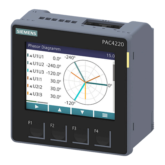
Operation 6.2 Special displays Special displays 6.2.1 Phasor diagram The phasor diagram provides a coherent picture of the actual unbalance values of the fundamental. The graphical representation is assigned a value table. F1 switches between the two representations. Special displays of the phasor diagram ①... -
Page 74: Measurement Of 1St To 64Th Harmonics For Voltage And Current
Operation 6.2 Special displays 6.2.2 Measurement of 1st to 64th harmonics for voltage and current Harmonics are mainly caused by equipment with a non-linear characteristic, such as fluorescent lamps, transformers and frequency converters. They are integer multiples of a fundamental. The harmonics place a thermal load on the network. As well as causing functional impairments, they can shorten the service life of the devices or cause irreparable device damage. - Page 75 Operation 6.2 Special displays Displaying harmonics on the PAC4220 display: 1. Select the "Display" submenu of the "Settings" menu. 2. You can select the display type in the menu option "FFT display type": – Harmonics "3, 5, 7 ... 63" (display of odd harmonics) –...
- Page 76 Operation 6.2 Special displays 3. The following harmonic displays are available on the device display: – Harmonic UL-N – Harmonic UL-L – Harmonic I 4. You can call the following additional functions using the F1 key – Max values – Delete max values PAC4220 Equipment Manual, L1V30827278B-01...
- Page 77 Operation 6.2 Special displays – Scroll right/left You can find more information in chapter Readout of harmonic components of all harmonics with function codes 0x03 and 0x04 (Page 126). PAC4220 Equipment Manual, L1V30827278B-01...
-
Page 78: Supporting Software
In addition to cost savings through optimized consumption, you ensure increased resilience with the monitoring of power supply systems and network quality in infrastructure and industrial plants. You can find more information on the internet. • Website (https://support.industry.siemens.com/cs/document/109764480/sentron- energiemanagement-und-energiemonitoring?dti=0&lc=de-DE) • Powerconfig software (https://mall.industry.siemens.com/mall/de/WW/Catalog/Products/ 10121795) •... -
Page 79: Sentron Powerconfig
6.3.3 Advanced training courses Find out about training courses on offer via the following link: Training for Industry (https://www.siemens.de/sitrain-lowvoltage) Here you can choose between: web-based training courses (online, informative, free of charge) Classroom training courses (in-person event, comprehensive, subject to fee) - Page 80 Operation 6.3 Supporting software PAC4220 Equipment Manual, L1V30827278B-01...
-
Page 81: Parameterizing
Parameterizing Device settings The "Parameterizing" chapter describes the device settings. This includes: • Adjustment to the physical conditions of use • Integration into the communications system • Country-specific settings, ergonomics, device protection It is possible to set the device by means of: •... -
Page 82: Parameterizing Via The Operator Interface
Parameterizing 7.1 Parameterizing via the operator interface Parameterizing via the operator interface You can parameterize the PAC4220 via the "Settings" menu option. You can find more information on this in chapter Menu-based navigation (Page 66). The device settings are arranged into the following groups. The "SETTINGS" menu shows the choice of groups: •... -
Page 83: Language/Regional
Parameterizing 7.1 Parameterizing via the operator interface 7.1.2 Language/Regional You set the language of menu-based operation and of the measured value displays in the "Language/Regional" menu item. Selection Range Factory setting Language English, German English Phase labels L1, L2, L3 • L1, L2, L3 •... - Page 84 Parameterizing 7.1 Parameterizing via the operator interface Voltage input Selection Range Factory setting Connection type 3P4W • 3P4W 3 phases, 4 conductors, unbalanced load • 3P3W 3 phases, 3 conductors, unbalanced load • 3P4WB 3 phases, 4 conductors, balanced load • 3P3WB 3 phases, 3 conductors, unbalanced load •...
-
Page 85: Date/Time
Parameterizing 7.1 Parameterizing via the operator interface Selection Range Factory setting DISPLAY RANGE Resolution of current indication 50 A Freely adjustable 1 A ... 99999 A • CURRENT DIREC L1 Inverse evaluation of the current flow direction separately for OFF each phase. • CURRENT DIREC L2 •... -
Page 86: Communication
Parameterizing 7.1 Parameterizing via the operator interface Selection Range Factory setting TIME ZONE Time zone, refers to coordinated universal time (UTC). 00:00 −12:00 ... +14:00, in 30-minute intervals DAYLIGHTSAVING Automatic time change AUTO EU 7.1.5 Communication You configure the communication interface in this menu. If you exit the "COMMUNICATION"... -
Page 87: Display
Parameterizing 7.1 Parameterizing via the operator interface 7.1.6 Display Selection Range Factory setting FFT DISPLAY TYPE The device gives you the option of displaying the odd (3rd to 3, 5, 7 ... 63 63rd) or all (1st to 64th) harmonics on the PAC4220 display. •... -
Page 88: Advanced
Parameterizing 7.1 Parameterizing via the operator interface 7.1.7 Advanced 7.1.7.1 Overview 7.1.7.2 Write protection Write protection The hardware write protection prevents write access to the device, both via the communications interface and on the display. In order to gain write access, the hardware write protection must be deactivated directly on the device. - Page 89 Parameterizing 7.1 Parameterizing via the operator interface The user must adjust the position of the write protection slider on the rear panel of the device in order to activate or deactivate the hardware write protection function. Selection Range Factory setting WRITE PROTECTION Write access is not possible when the hardware OFF write protection is activated.
-
Page 90: Protection Against Tampering
Parameterizing 7.2 Protection against tampering Protection against tampering 7.2.1 Cybersecurity In order to be able to operate devices of the SENTRON product group in a cybersecure manner, it is necessary to combine the devices/applications into a cybersecure network. The following link takes you to an application example illustrating the principles of the network technology in which an exemplary cybersecurity configuration structure is shown. -
Page 91: Protection Against Unauthorized Operation
: Device is protected against write access. • : Device is not protected against write access. Note Siemens recommends activating the tamper protection mechanisms in the device. 7.2.3 Protection against unauthorized operation Protection against unauthorized operation prevents write access via the device interface and the communication interfaces, in particular: •... - Page 92 Parameterizing 7.2 Protection against tampering becomes visible on the display when protection against unauthorized operation is switched off. The password remains saved and becomes effective again the next time protection against unauthorized operation is switched on. Note Before you switch on protection against unauthorized operation, make sure that you and the group of authorized users are all in possession of the password.
-
Page 93: Device Access Control (Ip Allowlist)
Parameterizing 7.2 Protection against tampering 7.2.4 Device access control (IP allowlist) The IP allowlist is a configurable access protection. If the IP allowlist is activated, Modbus TCP write commands are only accepted if the remote station is located in the same subnet. The IP allowlist can be activated on the device in the "Communication"... -
Page 94: Seal
Parameterizing 7.2 Protection against tampering Note Switching from standard port 502 to a user-defined port makes it more difficult to scan for open ports. Example PAC4220 No. 1 with IP allowlist is located in subnet 1 (192.168.100.0/24). PAC4220 No. 2 without IP allowlist is located in subnet 2 (192.168.98.0/24). •... -
Page 95: Service And Maintenance
• Unauthorized modifications or repairs • Disassembly or bypassing of safety features • Use of spare parts that are not original spare parts from SIEMENS AG • Mounting of the device with mounting clamps not originally supplied by SIEMENS AG •... -
Page 96: Calibration
Service and maintenance 8.1 Calibration Calibration The device requires no maintenance. The device has been calibrated by the manufacturer before shipping. Recalibration is not required provided the ambient conditions are maintained. PAC4220 Equipment Manual, L1V30827278B-01... -
Page 97: Cleaning
Service and maintenance 8.2 Cleaning Cleaning Clean the display and keys as required. Use a dry cloth for this. NOTICE Damage due to detergents Detergents can damage the device. Do not use detergents. PAC4220 Equipment Manual, L1V30827278B-01... -
Page 98: Firmware Update
Use the Powerconfig configuration software or the web server (port 9990) for updating the firmware. Additional information on updating the firmware can be found in the online help for Powerconfig. You can find the available firmware versions on the internet (https:// mall.industry.siemens.com/mall/de/WW/Catalog/Products/10121795). PAC4220 Equipment Manual, L1V30827278B-01... -
Page 99: Troubleshooting Guide
Fault indication in the display menu: • The device is defective and cannot be repaired. "VOID" If the device fault cannot be remedied by the measures given above, the device is probably defective. More help is available on the internet. (https://www.siemens.de/lowvoltage/support-request) PAC4220 Equipment Manual, L1V30827278B-01... -
Page 100: Warranty
Procedure Note Loss of warranty Opening the device will invalidate the Siemens warranty. Only the manufacturer is permitted to carry out repairs to the devices. If the device is faulty or damaged, proceed as follows (only during the warranty period): 1. -
Page 101: Disposal Of Waste Electronic Equipment
Service and maintenance 8.6 Disposal of waste electronic equipment Disposal of waste electronic equipment Disposal of waste electronic equipment Waste electronic equipment must not be disposed of as unsorted municipal waste, e.g. household waste. When disposing of waste electronic equipment, the current local national/ international regulations must be observed. - Page 102 Service and maintenance 8.6 Disposal of waste electronic equipment PAC4220 Equipment Manual, L1V30827278B-01...
-
Page 103: Technical Data
Technical data PAC4220 technical data Device configuration • 2 slots for up to 2 optional expansion modules • 2 opto-isolated digital inputs • 2 opto-isolated digital outputs • 2 Ethernet interfaces for connecting to the PC or network Measurement Only for connection to alternating voltage systems Measuring method ... - Page 104 Technical data 9.1 PAC4220 technical data Measuring inputs for voltage Input resistance (L N) 1.5 MΩ Max. power consumption per phase 150 mW Measuring inputs for current Measuring inputs for current Input current I Rated current 1 x/1 A Rated current 2 x/5 A Measuring range of current 10 ... 120% of rated current...
- Page 105 Technical data 9.1 PAC4220 technical data Supply voltage Supply voltage Wide-range AC/DC power supply unit 7KM4220-0BA01-1EA0 AC: 95 ... 250 V (+/-10%), max. 28 VA / 6 W DC: 110 ... 270 V (+/-10%), max. 6 W Extra-low voltage DC power supply unit 7KM4220-1BA01-1EA0 DC: 24 ...
- Page 106 Technical data 9.1 PAC4220 technical data Communication Ethernet interface Number of connections Type RJ45 Suitable cable types 100Base-TX (CAT5) Protocols supported Modbus TCP; web server (HTTP), SNTP; DHCP Transfer rates 10/100 Mbit/s, autonegotiation und Auto‑MDI-X (Medium De‐ pendent Interface) Update time at the interface 500 ms for instantaneous values and energy counters Displays and controls Display...
- Page 107 Technical data 9.1 PAC4220 technical data Connection components: Current connection, voltage connection 2-wire, same cross-section Rigid 0.2 ... 1.5 mm (AWG 24 ... 16) Flexible 0.2 ... 1.5 mm (AWG 24 ... 16) Flexible with end sleeve, without plastic 0.25 ... 0.75 mm sleeve (AWG 24 ... 19) Flexible with TWIN end sleeve and plastic 0.5 ...
- Page 108 Technical data 9.1 PAC4220 technical data Connection components: Digital inputs and outputs 2-wire, same cross-section Rigid 0.14 ... 0.75 mm (AWG 26 ... 19) Flexible 0.14 ... 0.75 mm (AWG 26 ... 19) Flexible with end sleeve, without plastic 0.25 ... 0.5 mm sleeve (AWG 24 ... 20) Flexible with TWIN end sleeve and plastic 0.5 ...
- Page 109 Technical data 9.1 PAC4220 technical data Ambient conditions The device is suitable for panel mounting in accordance with IEC 61554. Operation is only permissible inside an enclosed, dry room. Ambient conditions Temperature range Ambient temperature while -25 °C ... +55 °C (K55) in operation ...
- Page 110 The applied directives and standards can be found in the EU Declaration of Conformity. Approval for Australia and New Zealand Regulatory Compliance Mark Approval for Eurasian Economic Union You can download the relevant certificates from the Siemens Support website (https:// support.industry.siemens.com/cs/ww/de/view/109764140). PAC4220...
-
Page 111: Labeling
Technical data 9.2 Labeling Labeling View of a typical rating plate illustrated by the example of a PAC4220 (230 V) device Table 9-1 Legend Item Symbol, Explanation label – Name of the device – Article number of the device – Serial number of the device –... - Page 112 Technical data 9.2 Labeling Item Symbol, Explanation label (10) Electrical installation and maintenance by qualified personnel only (11) The device must not be disposed of with general domestic waste. (12) RCM test symbol (Australia and New Zealand) (in preparation) (13) Protective insulation - class II device (14) CE marking (European Union) (15)
-
Page 113: Dimensional Drawings
Dimensional drawings 10.1 PAC4220 dimensional drawings Panel cutout Figure 10-1 Panel cutout Frame dimensions 96 mm [3.8 in] 58 mm [2.3 in] Figure 10-2 Frame dimensions PAC4220 Equipment Manual, L1V30827278B-01... - Page 114 Dimensional drawings 10.1 PAC4220 dimensional drawings Clearance measurements L = 30 mm if mounting brackets supplied with the device are used L = 5 mm if compact brackets available to order as separate components are used (article number: 7KM9900-0GA00-0AA0) PAC4220 Equipment Manual, L1V30827278B-01...
-
Page 115: Appendix
Appendix Modbus A.1.1 Modbus Detailed information about Modbus can be found at the Modbus website (https://modbus.org/). You can access the following measured variables: • Via the Ethernet interface with the Modbus TCP protocol • Via the PAC RS485 expansion module with the Modbus RTU protocol More information You can find further details about the PAC RS485 expansion module and Modus RTU in the "PAC RS485 Expansion Module"... -
Page 116: Exception Codes
Appendix A.1 Modbus A.1.3 Exception codes Overview Table A-1 Modbus exception codes Exception code Name Meaning Remedy Illegal Function Illegal function: Check which function codes are supported. • The function code in the request is not a permissible action for the device. •... -
Page 117: Measured Variables Without A Time Stamp With The Function Codes 0X03 And 0X04
Appendix A.1 Modbus A.1.4 Measured variables without a time stamp with the function codes 0x03 and 0x04 Addressing the measured variables without a time stamp The PAC4220 Power Monitoring Device provides measured variables with or without a time stamp. Note Error in the case of inconsistent access to measured values Please ensure the start offset of the register is correct when making read accesses. - Page 118 Appendix A.1 Modbus Offset Number Name Format Unit Value range Access of regis‐ ters THD voltage L3‑L1 Float 0 … 100 Line frequency Float 45 … 65 3-phase average voltage L‑N Float ‑ 3-phase average voltage L‑L Float ‑ 3-phase average current Float ‑ Total apparent power Float ‑...
- Page 119 Appendix A.1 Modbus Offset Number Name Format Unit Value range Access of regis‐ ters Minimum voltage L1‑L2 Float ‑ Minimum voltage L2‑L3 Float ‑ Minimum voltage L3‑L1 Float ‑ Minimum current L1 Float ‑ Minimum current L2 Float ‑ Minimum current L3 Float ‑...
-
Page 120: Tariff-Specific Energy Values In Double Format With The Function Codes 0X03, 0X04, And 0X10
Appendix A.1 Modbus Offset Number Name Format Unit Value range Access of regis‐ ters Total reactive power L2 (Qtot) Float ‑ Total reactive power L3 (Qtot) Float ‑ Reactive power L1 (Q1) Float ‑ Reactive power L1 (Q1) Float ‑ Reactive power L1 (Q1) Float ‑ Unbalance voltage Float 0 … 100 Unbalance current Float 0 … 100 Neutral current... - Page 121 Appendix A.1 Modbus Offset Number Name Format Unit Value range Access of regis‐ ters Apparent energy tariff 1 Double Overflow 1.0e+12 Apparent energy tariff 2 Double Overflow 1.0e+12 Process active energy Double Overflow 1.0e+12 Process reactive energy Double VARh Overflow 1.0e+12 Process apparent energy Double Overflow 1.0e+12 Process active energy – previous meas‐ Double urement Process reactive energy –...
-
Page 122: Tariff-Specific Energy Values In Float Format With The Function Codes 0X03 And 0X04
Appendix A.1 Modbus Offset Number Name Format Unit Value range Access of regis‐ ters Secondary total of active energy - im‐ Double port (MID register) Secondary total of active energy - ex‐ Double port (MID register) Total of active energy - import (MID reg‐ Double ister) Total of active energy - export (MID reg‐... - Page 123 Appendix A.1 Modbus Offset Number Name Format Unit Value range Access of regis‐ ters 2827 Process active energy – previous meas‐ Float urement 2829 Process reactive energy – previous Float VARh measurement 2831 Process apparent energy – previous Float measurement 2833 L1 active energy import tariff 1 Float overflow 1.0e+12...
-
Page 124: Odd Harmonics Without A Time Stamp With The Function Codes 0X03 And 0X04
Appendix A.1 Modbus Offset Number Name Format Unit Value range Access of regis‐ ters 2897 Total of active energy - import (MID reg‐ Float overflow 1.0e+12 ister) 2899 Total of active energy - export (MID reg‐ Float overflow 1.0e+12 ister) Table A-7 Meaning of the abbreviations in the "Access"... - Page 125 Appendix A.1 Modbus Tables Offset Length Name Format Unit Access FC0x03 FC0x04 9001 Fundamental voltage L1-N FLOAT 9003 Fundamental voltage L2-N FLOAT 9005 Fundamental voltage L3-N FLOAT 9007 3rd harmonic voltage L1-N FLOAT 9009 3rd harmonic voltage L2-N FLOAT 9011 3rd harmonic voltage L3-N FLOAT nth Harmonic voltage L1-N FLOAT...
-
Page 126: Odd Harmonics With A Time Stamp With The Function Codes 0X03 And 0X04
Appendix A.1 Modbus Offset Length Name Format Unit Access FC0x03 FC0x04 nth Harmonic voltage L1-L2 FLOAT formula nth Harmonic voltage L2-L3 FLOAT formula nth Harmonic voltage L3-L1 FLOAT formula A.1.8 Odd harmonics with a time stamp with the function codes 0x03 and 0x04 Formula The offsets of the 5th to 65th odd harmonics can be calculated using the formula below: nth - stands for the number of the harmonic... - Page 127 Appendix A.1 Modbus Offset Length Name Format Unit Access FC0x03 FC0x04 Max. nth harmonic voltage L2-N with time FLOAT+TIME‐ formula STAMP Max. nth harmonic voltage L3-N with time FLOAT+TIME‐ formula STAMP Offset Length Name Format Unit Access FC0x03 FC0x04 19001 Maximum fundamental current L1 with time FLOAT+TIME‐...
-
Page 128: Readout Of Harmonic Components Of All Harmonics With Function Codes 0X03 And 0X04
Appendix A.1 Modbus A.1.9 Readout of harmonic components of all harmonics with function codes 0x03 and 0x04 For clarity, only the 1st and the 64th harmonics are listed in the table. Formula The offsets of the 2nd to 63rd harmonics can be calculated using the formula below: nth - stands for the number of the harmonic Example 1 Calculation of offset of "3rd harmonic voltage L1-N"... - Page 129 Appendix A.1 Modbus Length Offset Name Format Unit Access FC0x03 FC0x04 nth Harmonic voltage L2-N FLOAT formula 36259 64th harmonic voltage L2-N FLOAT 36261 1st harmonic voltage L3-N FLOAT nth Harmonic voltage L3-N FLOAT formula 36387 64th harmonic voltage L3-N FLOAT File Length Offset Offset Name Format Unit Access...
- Page 130 Appendix A.1 Modbus File Length Offset Offset Name Format Unit Access FC0x14 FC0x14 FC0x03 FC0x04 37201 1st max. harmonic voltage L1-N FLOAT+TS32 nth max. harmonic voltage L1-N FLOAT formula formula 37453 64th max. harmonic voltage L1-N FLOAT+TS32 37457 1st max. harmonic voltage L2-N FLOAT+TS32 nth max.
-
Page 131: Configuration Settings With The Function Codes 0X03, 0X04, And 0X10
Appendix A.1 Modbus File Length Offset Offset Name Format Unit Access FC0x14 FC0x14 FC0x03 FC0x04 2045 39245 64th max. harmonic voltage L2- FLOAT+TS32 2049 39249 1st max. harmonic voltage L3-L1 FLOAT+TS32 nth max. harmonic voltage L3-L1 FLOAT+TS32 formula formula 2301 39501 64th max. harmonic voltage L3- FLOAT+TS32 A.1.10 Configuration settings with the function codes 0x03, 0x04, and 0x10... - Page 132 Appendix A.1 Modbus Offset Number Name Format Unit Value range Access of regis‐ ters 50047 Dialog Language Unsigned long ‑ 0 = German 1 = English 50049 Phase identifier IEC/UL Unsigned long 0 = 1 = 50057 Display Backlight Level Unsigned long 0 … 3 50059 Display Backlight Dimmed Unsigned long 0 … 3 50061...
- Page 133 Appendix A.1 Modbus Offset Number Name Format Unit Value range Access of regis‐ ters 50261 Default menu No. Unsigned long DISPLAYED MENU NUMBER: 1 MEAS_VLN 2 MEAS_VLL 3 MEAS_I 4 MEAS_S 5 MEAS_P 6 MEAS_Q 7 MEAS_SPQ 8 MEAS_PF 9 MEAS_PFSUM 10 MEAS_COS 11 MEAS_F 12 MEAS_THDU...
- Page 134 Appendix A.1 Modbus Offset Number Name Format Unit Value range Access of regis‐ ters 50289 IP Filter Allowlist Entry #1 Unsigned long Bit0: Deactivated Flags Bit1: Read MODBUS Bit2: Write MODBUS 50291 IP Filter Allowlist Entry #2 IP Unsigned long 0..0xFFFFFFFF Network Address 50293 IP Filter Allowlist Entry #2 IP...
-
Page 135: I&M Settings
Appendix A.1 Modbus A.1.11 I&M settings Addressing the settings for the I&M data Table A-9 Settings for the I&M data Offset Number Name Format Unit Applicable MOD‐ Value range Access of regis‐ BUS function co‐ ters 64001 PAC4220 I&M 0 data stIM0 R(W) •... -
Page 136: Modbus Standard Device Identification With The Function Code 0X2B
Appendix A.1 Modbus A.1.13 MODBUS standard device identification with the function code 0x2B Addressing the MODBUS standard device identification You can use Modbus function code 0x2B on these device identification parameters. Table A-11 MODBUS standard device identification parameters Object ID Name Format Access OID 0... - Page 138 Further Information SI EP online...
Need help?
Do you have a question about the SENTRON PAC4220 and is the answer not in the manual?
Questions and answers