Siemens SITRANS F Operating Instructions Manual
Ultrasonic flowmeters
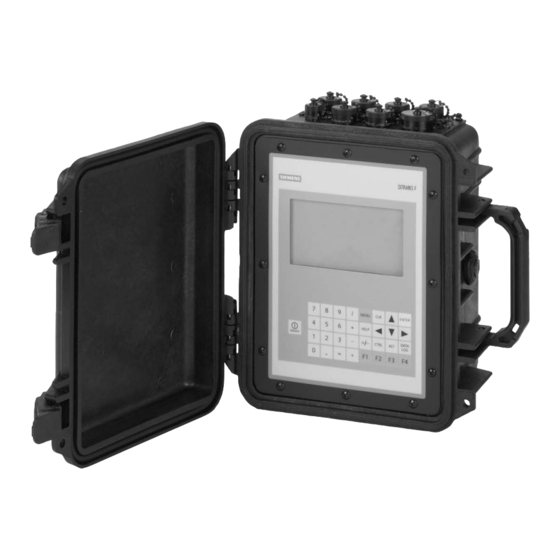
portable flowmeter
Hide thumbs
Also See for SITRANS F:
- Function manual (350 pages) ,
- Instruction manual (306 pages) ,
- Operating instructions manual (225 pages)

Related Manuals for Siemens SITRANS F


Summary of Contents for Siemens SITRANS F
- Page 1 SITRANS F Ultrasonic Flowmeters SITRANS 1010AERWDP Portable Flowmeter Operating Instructions Edition 12/2014 Answers for industry.
- Page 3 (ESD). Please observe ESD control measures during the handling and connection process. Field Manual A5E02617285 Rev AB December 2014 For use with Operating System Software Version 3.01.06F or later Copyright©2014 Siemens Industry, Inc. All Rights Reserved Made in the USA...
- Page 4 Manual Changes NOTE: For the latest updates and revisions to this field manual go to: http://support.automation.siemens.com/ and check the Product Manual listing.
- Page 5 1010FMA-56 MANUAL ADDENDUM Operating System Software Version Update Manual Addendum September 2008 Copyright © 2008 Siemens Industry, Inc. All rights reserved Made in the USA...
- Page 7 1010FMA-56 Manual Addendum Operating System Software Version Update INTRODUCTION The following software operating system version update is for Version 3 flowmeters. Please refer to this addendum when using this technical manual with Version 3 operating system software and flowmeters that have been updated to Version 5. Operating System Software Changes 1.
- Page 8 Gas Flowmeter Flow and VoS Unit Changes 1. Flowmeter Types Flowmeter configurations included with this change include all SITRANS F Gas Flowmeters (7ME361*). 2. Flow Units The table below describes the translation from the current gas flow units to the new gas flow units, where only Cubic Feet and Cubic Meter volume units are affected.
- Page 9 1010FMA-56 Manual Addendum 3. Total Units Total units are similar to flow units. TOTALIZE UNITS For STD VOLUME disabled Version 3 Version 5 CU FT KCU FT MACF MCU FT MMACF KCU M E3 M3 MCU M E6 M3 TOTALIZE UNITS For STD VOLUME enabled Version 3 Version 5...
- Page 11 1010FMA-58 MANUAL ADDENDUM Digital Damping Procedure Update For Gas & Liquid Flowmeters Manual Addendum September 2008 Copyright © 2008 Siemens Industry, Inc. All rights reserved Made in the USA...
- Page 13 Digital Damping Procedure Update for Gas & Liquid Flowmeters INTRODUCTION The following Digital Damping procedure updates are for SITRANS F gas and liquid clamp-on flowmeters.Replace the Digital Damping Control: (Hot Key 1 and 2) procedure in the “Detection Modes” section (sub-paragraph: Command Modes) in the appropriate gas and liquid STIRANS F flowmeter manuals.
- Page 14 Manual Addendum 1010FMA-58 To access the Digital Damping Control using the Test Facilities Graph Screen, proceed as follows: 1. To use the Test Facilities Graph Screen you must have a working site. 2. To activate the Test Facilities Graph Screen: In the main menu, scroll to the [Diagnostic Data] menu and select [Test Facilities].
- Page 15 1010FMA-58 Manual Addendum To INCREASE the Digital Damping: 1. Press the <1> key while viewing the Test Facilities Graph Screen as shown above. The damping control [MinDamp #] should appear on the command line at the lower left-hand corner of the screen.
- Page 16 Manual Addendum 1010FMA-58 Liquid Clamp-on Flowmeter Manuals Replace the Digital Damping Control: (Hot Key 1 and 2) procedure in the “Detection Modes” section (sub-paragraph: Command Modes) in the following flowmeter manuals: FUS1010 IP 65 (NEMA 4X) Clamp-On Flowmeter manual (CQO:1010NFM-3) FUE1010 IP 65 (NEMA 4X) Clamp-On Flowmeter manual (CQO:1010ENFM-3) FUH1010 IP 65 (NEMA 4X) Clamp-On Flowmeter manual (CQO:1010DVNFM-3) FUH1010 IP 65 (NEMA 4X) Clamp-On Flowmeter manual (CQO:1010PVNFM-3)
- Page 17 1010FMA-58 Manual Addendum To access the Digital Damping Control using the Test Facilities Graph Screen, proceed as follows: 1. To use the Test Facilities Graph Screen you must have a working site. 2. To activate the Test Facilities Graph Screen: In the main menu, scroll to the [Diagnostic Data] menu and select [Test Facilities].
- Page 18 Manual Addendum 1010FMA-58 To INCREASE the Digital Damping: 1. Press the <1> key while viewing the Test Facilities Graph Screen as shown above. The damping control [MinDamp #] should appear on the command line at the lower left-hand corner of the screen.
- Page 19 1010FMA-22 MANUAL ADDENDUM System 1010AP/AER Ultrasonic Aerospace Portable Flowmeter Manual Addendum 1010FMA-22 March 2007 Copyright © 2007 Siemens Industry, Inc all Rights Reserved Made in the USA...
- Page 21 1010AERWDP TRANSDUCER INSTALLATION INTRODUCTION The System 1010AERWDP flowmeters are part of Siemens extensive System FUS 1010 Clamp- On Transit-Time Ultrasonic Flowmeter division. These meters have all the capabilities of the FUS1010 Clamp-On Series flowmeters plus all the added features of the Aerospace line, which is specifically designed to accurately and non-intrusively measure flow in steel, aluminum, and titanium tubing typically used in aircraft hydraulic and fuel systems.
- Page 22 In this example, [SITE1] will be used for the site name. To access the [Channel Setup] menu press the <Right> arrow, then move the highlight down to [Create/Name Site]. Siemens Site Right Arrow & Enter Creates a new Site Recall Site Setup...
- Page 23 Selecting Pipe Data Press the <Down> arrow to select Pipe Data, then press the <Right> arrow. Siemens Site SITE1 Enter Pipe Outer Diameter manually Pipe OD (in) 1.000 Pipe Material Steel Wall Thickness 0.035 Liner Material None Liner Thickness 0.000 Pipe Data To select Pipe OD (in), press the <Right>...
- Page 24 <Right> arrow. The meter will display only the transducers that are suitable for the entered tube diameter. The prompt line will display the recommended transducer part number based on the entered wall thickness as indicated in Table 2 on page 9 of this addendum. Siemens Site SITE1 Recommended Xdcr: 1011AP-16S2-B...
- Page 25 Press the <Down> arrow to select Install Completed?, then press the <Right> arrow. Siemens Site SITE1 Key [Install] after mounting transducers Transducer P/N 1011AP-16S2-B Install Completed? *Install Empty Pipe Set Chan Not Setup Zero Flow Adjust Chan Not Setup Pick/Install Xdcr Use the <UP>...
- Page 26 After the meter completes its Initial Makeup command, the [Installed Completed?] option list changes to: Install Completed? New Makeup If you want to redo the Initial Makeup, move cursor to New Makeup, then press the <ENT> key. This resets the option list. You can now repeat the install routine described previously. Refer to the FUP1010 Portable field manual for the Empty Pipe Set procedure.
- Page 28 Wall Thickness Range (in) OD (in) 0.015 to 0.042 0.015 to 0.042 0.043 to 0.061 0.062 to 0.084 0.085 to 0.116 1011AP-4S1-B 1011AP-5S1-B 1011AP-6S1-B 1011AP-8S1-B 1011AP-8S2-B 1011AP-10S2-B 1011AP-10S3-B 1011AP-12S2-B 1011AP-12S3-B 1011AP-12S4-B 1011AP-14S2-B 1011AP-14S3-B 1011AP-14S4-B 1011AP-16S2-B 1011AP-16S3-B 1011AP-16S4-B 1 1/8 1011AP-18S2-B 1011AP-18S3-B 1011AP-18S4-B 1011AP-18S5-B...
- Page 31 1010FMA-4 MANUAL ADDENDUM SETUP PROCEDURE FOR WET-FLOW CALIBRATED Sitrans F SYSTEMS Sitrans F Uniflow Portable & NEMA Flowmeter Systems Manual Addendum July 2002 Copyright©2007 Siemens Industry, Inc. All Rights Reserved Made in the USA...
- Page 33 Manual Addendum 1010FMA-4 SETUP PROCEDURE FOR “WET-FLOW CALIBRATED” 1010 SYSTEM Caution: DO NOT use the field manual installation procedure to startup a wet-flow calibrated system. Doing so could void the calibration by corrupting es- sential data. This addendum contains the only authorized instructions to be used when commissioning a wet-flow calibrated 1010 system.
- Page 34 2.2.11 When measurements are completed, simply turn off the meter. DO NOT save the site. This might contaminate the wet-flow calibration data already stored. NOTE: Contact Siemens’ Technical Services Department if any flow calibration data is accidentally removed or overwritten.
- Page 35 Manual Addendum 1010FMA-4 TRANSFER INSTALL FUNCTION All 1010 flowmeter operating systems (version 3.00.20 and greater) include the installation facil- ity called “Transfer Install.” This function permits the transducers to be repositioned while main- taining all calibration parameters and operation established during the water calibration. The Transfer Install function allows the transducers to be optimally positioned for a different fluid, without the need for a new Initial Makeup procedure.
-
Page 37: Table Of Contents
Table Of Contents 1010PFM-3G Table of Contents Sect./Page Section 1 Introduction ......................1-1 About This Field Manual ..................1-1 Conventions ......................1-1 1.1.1 General Installation Menu Notes ................ 1-1 1.1.2 Introducing the FUP 1010P/WDP Flowmeter ............1-2 Portable Configurations ..................1-2 1.2.1 Standard Portable Features ................. - Page 38 Table Of Contents 1010PFM-3G Forming the Battery (Optimizing Operating Time) ........... 1-22 1.10.2 How to Use the Battery Charger ................ 1-22 1.10.3 1015BC-1 Battery Charger ................1-22 1015BC Power Adapter/Charger ..............1-24 1015BW Power Adapter/Charger ..............1-24 1010DP Dual-Channel Portable Flowmeter, Rear View ........1-25 1010DP Input/Output Terminals ...............
- Page 39 Table Of Contents 1010PFM-3G How To Use The Spacing Offset ............... 2-19 2.4.5 Letter Index (1011 Transducer) - Letter and Number Index (990 Trans- ....2.4.6 ducer) ........................2-20 The 1011 Transducer ..................2-20 The 990 Transducer ..................2-20 The Number Index Menu Cell ................2-20 2.4.7 The Ltn Menu Cell ....................
- Page 40 Table Of Contents 1010PFM-3G High Flow ......................2-41 Low Flow ......................2-41 High Temperature..................... 2-41 Low Temperature ..................... 2-41 Interface Vs (m/s) meters-per-second ............... 2-42 Aeration % ......................2-42 Makeup Latch ....................2-42 Calibrate Flow Rate ..................... 2-43 2.7.3 Kc Calibration ....................2-43 MultiPoint Calibration ..................
- Page 41 Table Of Contents 1010PFM-3G The Site Setup Data Menu .................. 2-62 2.11.5 Site Setup Menu Items ..................2-62 Introduction to [HF] Menu Item ................. 2-63 Using The [HF] Menu Item ................2-63 “Manual” Adjustment Procedure ............... 2-64 “Automatic” Adjustment Procedure ..............2-65 The Test Facilities Menu ..................
- Page 42 Table Of Contents 1010PFM-3G Section 4 The Meter Facilities Menu and Graphic Display Screens ........ 4-1 Preferred Units...................... 4-1 The Table Setups Menu ..................4-2 Pipe Table ......................4-2 4.2.1 Pipe Table Menu Structure ................. 4-2 Create/Edit Pipe ....................4-3 4.2.2 Delete Pipe ......................
- Page 43 Table Of Contents 1010PFM-3G Section 5 System 1010P Application Notes ................. 5-1 To Obtain Technical Assistance ................5-1 Considerations For Critical Applications ............5-1 Pipe Considerations For Clamp-On Transducers ..........5-2 Pipe Dimensions ....................5-2 5.3.1 Picking The Appropriate Transducer ..............5-2 5.3.2 Flow Velocity Range ....................
- Page 44 Table Of Contents 1010PFM-3G Considerations For Critical Applications ............. 6-3 To Obtain Technical Information ................. 6-3 How To Set Up System 1010P for Flow Tube Operation ........6-4 Overview ........................ 6-4 6.3.1 Setup Procedure ....................6-4 6.3.2 Specifications - CPVC Flow Tube ................ 6-9 Specifications - KYNAR PVDF Flow Tube ............
-
Page 45: Introduction
This field manual is designed to enable someone with no prior experience to setup and operate the Siemens SITRANS FUP 1010P Portable Flowmeter. Please visit our web site: www.siemens.com. There you will find additional documentation for downloading including updated news about the com- pany and our products. -
Page 46: Introducing The Fup 1010P/Wdp Flowmeter
They represent the state-of-the-art in computerized instrumentation. We are confident that in a very short period of time you will appreciate your meter’s unrivaled performance and features, especially Siemens’ ground-breaking enhanced transit-time Digitally Coded MultiPulse technology and the on-line automatic and interactive site setup help facility. -
Page 47: Standard Portable Features
Section 1 1010PFM-3G 1.2.2 STANDARD PORTABLE FEATURES All 1010 models shown include the following standard features: Large 240 X 128 Pixel Display with 1-1/8 inch Characters Viewable from over 40 feet (12 meters) Allows hands-free operation with portable systems Graphics ability allows simultaneous digital and stripchart displays Push-button scrolling through all available graphic displays System 1010WP(DP) Portable Flowmeters Single Path or Dual Channel/Path Operation... - Page 48 Section 1 1010PFM-3G Flexible Transducer Mounting Options EZ clamp and spacer bars make installing and spacing transducers fast and easy. Lightweight, rigid transducer mounting frames that can be coupled using spacer bars or in- stalled separately for stand-alone mounting. Fixed length mounting tracks (for small transducers). Mechanical, Electrical, Environmental and Safety Specifications Weight, 1010P 7.5 lbs / 3.4 kg...
-
Page 49: Performance
Section 1 1010PFM-3G 1.2.3 PERFORMANCE Under standard conditions (measurements taken on a straight run of 15 diameters upstream and 5 diameters downstream; flow rate above 1 fps; non-aerated Newtonian liquids flowing at Reynolds numbers <2000 or >10000). Transit-Time Accuracy At least 1% to 2 % of indicated flow (better than 0.5 % pos- sible with calibration. -
Page 50: Alarm Functions
Section 1 1010PFM-3G Alarm Functions The 1010P flowmeters offer several alarms (shown by letter codes on the digital screen and in data- logger reports). Alarm relays are not standard equipment in the 1010 Portable systems, since they use significant battery current to sustain fail-safe operation. However, System 1010P provides buffered logic outputs (3 - 5 Vdc high, 0 - 1 Vdc low) for external device control which can be used as triggers for external relays, etc. -
Page 51: Channel Functions
All the 1010 models use transit-time flow measurement technology varying only in functionality and environmental housings. System 1010 improves the MultiPulse signal detection first used in 990 mod- els by incorporating Siemens’ new Digitally Coded MultiPulse technology (DCM) featuring AutoMark receive signal detection. -
Page 52: Getting Started
Explosive Atmospheres. It is the user’s responsibility to ensure that properly trained personnel install and operate this equipment, and use it in Ordinary Locations only. If the equipment is used in a manner not specified by Siemens, the safety protection provided by the equipment may be impaired. -
Page 53: Typical System- 1010P Portable Flowmeter Installation
Section 1 1010PFM-3G SPACER BAR Flow UPSTREAM TRANSDUCER FRAME ASSEMBLY MOUNTING CHAIN DOWNSTREAM TRANSDUCER ASSEMBLY FLOW COMPUTER GRAPHIC DISPLAY UNIFLOW SCREEN POWER KEYPAD ON/OFF (Data Entry Interface) TYPICAL SYSTEM - FUP1010 PORTABLE FLOWMETER INSTALLATION Flow Measurement Sub-System... -
Page 54: The 1010P Keypad
The figure below shows a typical 1010P menu screen (e.g., Pipe Data Menu). Current Selected Current Selected Meter Type Measurement Channel Siemens 2 Channel [1] SITE 1 Menu Prompt Line Reverse video) Select Pipe Class from Pipe Table Select Pipe Class... -
Page 55: How To Use The Installation Menu
Section 1 1010PFM-3G EXPLANATION OF THE CALL-OUTS Menu Prompt Line When you select a menu cell, a highlighted text prompt appears on the top of the screen to explain the function of the cell. Current Selected [2 Channel] indicates Dual Channel meter operating mode selected. Meter Type Selected Channel The [1] indicates that measurement Channel 1 is currently selected. -
Page 56: Accessing And Leaving The Menu
1.9.1 ACCESSING AND LEAVING THE MENU Upon first turning the meter on you see a Siemens graphic. This means that there is no active site setup currently stored in memory. Note that this screen identifies the software version of the meter on the upper right-hand corner of the display. -
Page 57: Selecting Items From An Option List
[Application Data] appears highlighted on lower left of the screen. Note also that the menu cell [Liquid Class] is highlighted and what is shown in the right-hand column is the current answer: [Water 20C/68F]. Siemens 2 Channel [1] Channel 1... -
Page 58: Multiple Select Option Lists
Section 1 1010PFM-3G Siemens 2 Channel [1] Channel 1 Access Liquid Option List Select Liquid 20% Ethyl Glycl Estimated Vs m/s 1600 Viscosity cS 2.00 Density SG 1.030 Liquid Class Multiple Select Option Lists Certain option lists allow you to make more than one selection. For example, the Datalogger Data option list allows you to select any or all of the available data items for your reports. -
Page 59: Entering Alphanumeric Strings
At the first character position, pressing the key (see below) produces an upper case [A]. Pressing key moves the cursor to the second position. Siemens Dual Path Channel 1 Right Arrow & Enter Creates a new Site... -
Page 60: Dual Channel Flow
Section 1 1010PFM-3G Dual Channel Flow Dual Channel Flow provides two independent measurement channels that operate simultaneously. Depending on the specific model, Dual Channel Flow supports: Clamp-on Transit-time, In-line Transit- time, and Reflexor. Channel 1 Pipe 'A' Flow Rate Flow PIPE `A' PIPE `B' Channel 2... -
Page 61: Multi-Channel Meter Types
Section 1 1010PFM-3G Multi-Channel Meter Types If your 1010 Model provides Multi-Channel Mode it offers you two independent measurement channels. The meter’s resources are divided among these channels equally. This means that analog Input/ Output, relays, and digital command lines will be fewer than for single channel machines. We will show you later how to “get around”... -
Page 62: Selecting A Meter Type
[Meter Type] screen. Refer to the figure below. Note that on the left-hand column, [Meter Type] is highlighted as are all the available meter types on the right- hand column. Press . This places a cursor next to [Dual-Channel Flow]. Siemens 2 Channel [1] Channel 1 Select Meter Type Meter Type >Dual Channel Flow... -
Page 63: Creating A New Site Setup
Section 1 1010PFM-3G Siemens 2 Channel [1] Channel 1 Choose Channel 1 Flowmeter Type Channel 1 >Clamp-on Channel 2 FlowTube Reflexor Channel Setup To select [Clamp-on] press . This selects the Clamp-on installation menu for Measurement Chan- nel 1. Note that the first menu, [Channel Setup], is highlighted. - Page 64 Section 1 1010PFM-3G Siemens 2 Channel [1] Channel 1 Right Arrow & Enter Creates a new Site Recall Site Setup No Sites Channel Enable Create/Name Site Site Security Delete Site Setup No Sites This block cursor is Save/Rename Site currently placed at the first character position.
-
Page 65: Battery Operation
Press to create the site setup named [SITE1]. Note that the name now appears in the [Save/ Rename Site] menu cell and on the upper right corner of the graphic screen. Siemens 2 Channel [1] SITE1 Use with Care -- Turn Security On or Off... -
Page 66: Forming The Battery (Optimizing Operating Time)
1015BC-1 Battery Charger 1. Do not use any other external Battery Charge/Pack combination with the 1010P Flowmeter unless reviewed and pre-approved by Siemens. 2. Do not leave the Battery Charger connected to the Battery Pack during transportation or storage. The battery/charger connector may be damaged or the battery may be discharged. - Page 67 Therefore, no user switching is required. 5. The AC power input of the 1015BC-1 uses a standard IEC 320 connection. Siemens can provide the appropriate power cord for proper connection to the AC outlets from most countries in the world.
-
Page 68: 1015Bc Power Adapter/Charger
Section 1 1010PFM-3G AC Cord Input Connect to 1010P Flow Computer input jack 1015BC Power Adapter/Charger 1-24... -
Page 69: 1010Dp Dual-Channel Portable Flowmeter, Rear View
Section 1 1010PFM-3G IR Interface Window RS-232 Port Input/Output Terminals Test Connector (for factory use only) Temperature Sensor Inputs DC Power Input Audible Signal Device LED Indicator Transducer Cable Connectors 1010DP Dual Channel Portable Flowmeter, Rear View 1-25... -
Page 70: 1010Dp Input/Output Terminals
Section 1 1010PFM-3G 1010DP INPUT/OUTPUT TERMINALS SIGNAL DESCRIPTION Signal Return Terminal [24 GA. (MIn) Max. Length: 1000 ft.] External Control Signal (HIGH=5 to 3 Vdc; LOW=1 to 0 Vdc) External Control Signal (HIGH=5 to 3 Vdc; LOW=1 to 0 Vdc) External Control Signal (HIGH=5 to 3 Vdc;... -
Page 71: 1010Wdp Portable Flowmeter, Rear View
Section 1 1010PFM-3G RS-232 Port Test Connector (for factory use only) Power Input (10.5 to 18.5 Vdc) Input/Output Port Charge Status LED Temperature 2 Sensor Temperature 1 Sensor Channel 2 Transducers Channel 1 Transducers Note: You may obtain cables for the Input/Output Port and RS-232 Port under the following part numbers: 1015WP26 - Input/Output Port to Breakout Box 1015CPC-WP - RS-232 Port to 9-pin and 25-pin DB Connectors... -
Page 72: 1010Wdp Input/Output Terminals
Section 1 1010PFM-3G 1010WDP INPUT/OUTPUT TERMINALS TERMINAL SIGNAL FUNCTION DESCRIPTION GND. SIGNAL GROUND Return For signals LOGIC OUT 1 Logic Level State [HIGH=5 TO 3 V; LOW=1 To 0 V] LOGIC OUT 2 Logic Level State [HIGH=5 TO 3 V; LOW=1 To 0 V] LOGIC OUT 3 Logic Level State [HIGH=5 TO 3 V;... -
Page 73: 1010Wp Single Channel Weatherproof Portable Flowmeter
Section 1 1010PFM-3G RS-232 Port Test Connector (for factory use only) Data Control/ Power Input Input/Output Connector (10.5 to 18.5 Vdc) Charge Status LED Flow Transducer Cable Connector Temperature Sensor Cable Connectors 1010WP Single Channel Weatherproof Portable Flowmeter 1-29... -
Page 74: 1010Wp Input/Output Terminals
Section 1 1010PFM-3G 1010WP INPUT/OUTPUT TERMINALS TERMINAL SIGNAL FUNCTION DESCRIPTION GND. SIGNAL GROUND Return For signals LOGIC OUT 1 Logic Level State [HIGH=5 TO 3 V; LOW=1 To 0 V] LOGIC OUT 2 Logic Level State [HIGH=5 TO 3 V; LOW=1 To 0 V] LOGIC OUT 3 Logic Level State [HIGH=5 TO 3 V;... -
Page 75: Using Faststart Setup
Pipe Class option list. Note that although [Manual Entry] exists on this list, it is inactive for FastStart Setup (see paragraph 2.2.1). Siemens In this example, we will pick the pipe class: [ASA Carbon Steel] by moving the cursor to the... -
Page 76: Picking And Installing The Transducers
. This is all there is to setting up the pipe parameters. Now, we will select and install the transducers. Siemens 1.11.2 PICKING AND INSTALLING THE TRANSDUCERS Press to access the Pick/Install Xdcr menu, then select the appropriate Transducer Model. The meter then analyzes your pipe data and registered transducer list before calculating the recommended transducer size(s). - Page 77 Section 1 1010PFM-3G Siemens NOTE: You are allowed to override the transducer type and size mounting mode and spacing offset. See paragraph 1.9. Now you have to mount the transducers in accordance with the data recommended on the screen. Refer to the Section 3 for detailed instructions. The pipe must be completely filled with a liquid for the initial installation of the meter.
- Page 78 [YES], or [NO] if you do not want to register this transducer. Press to register transducer. Siemens MENU The meter is now ready to report flow. Press the key. The meter will then ask you to save the Site.
-
Page 79: The 1010P Installation Menu
Section 2 1010PFM-3G THE 1010P INSTALLATION MENU Programming System 1010P requires no special experience or training. This field manual contains all the necessary information. If you intend to connect this instrument to an external device, then please have the instruction manual for the device available for reference. The following paragraphs present a generic menu reference that applies to all configurations of 1010 Portable meters. -
Page 80: The Channel Setup Menu
Save/Rename Site Site Name Entry/Edit Channel 1 active. This shows that the site setup [XYZ] is the active site. Siemens 2 Channel [1] Scroll saved Site Setup list and Enter Recall Site Setup Channel Enable This cell shows that Create/Name Site... -
Page 81: How To Enable And Disable A Measurement Channel
Section 2 1010PFM-3G transducers and make the required hardware connections. Note that the installed transducers must comply with the recalled site parameters. To recall a Saved Site Setup: (Where a visual of the keys is shown; this means press this key) To access the list of saved site names press To move the cursor to the Site Name press Press... -
Page 82: How To Create/Name A Site Setup
Therefore, it is essential that you never forget or misplace the password. The only way to deactivate Site Security without knowing the password is to return the unit to Siemens. However, the process the factory uses to remove site security will eliminate any existing site data as well. -
Page 83: How To Delete A Site Setup
Section 2 1010PFM-3G To select the first character, use the numeric keys or press To move the cursor to the first character position press To move the cursor to the second character position press Repeat the selection process for the second character. Continue this process until all the required characters (8 max.) appear in the field. -
Page 84: The Pipe Data Menu
To save the site data present in Active Memory press If Siemens Flowtalk software is used to save or restore sites, you can avoid ceating illegal file names by not using spaces or decimal points (.) in your site names. -
Page 85: Pipe Data Menu Structure
Section 2 1010PFM-3G THE PIPE DATA MENU STRUCTURE Pipe Data Select Pipe Class Manual Entry ASA Stainless Steel* ASA Carbon Steel ASA Plastic Metric DN Steel Metric SGP Steel Cast Iron Table Ductile Iron Table Copper Tube Table Select Pipe Size Manual Entry Set pipe parameters manually ASA Stainless Steel*... -
Page 86: How To Select A Pipe Class
Section 2 1010PFM-3G THE PIPE DATA MENU STRUCTURE (continued) Pipe Material Steel Pipe Data (cont.) Aluminum Black Iron Brass Cast Iron CuNi (70/30) CuNi (90/10) Copper Ductile Iron Glass Hastelloy Inconel Kynar (PVDF) Monel Nickel Polyethylene PVC (Plastic) Teflon Titanium Wall Thickness x.xxx (numeric entry) Liner Material... -
Page 87: How To Enter The Pipe Od (In. Or Mm.)
Section 2 1010PFM-3G After selecting a pipe class: To access the pipe size option list press To scroll to the required pipe press To register selection press 2.2.3 HOW TO ENTER THE PIPE OD (in. or mm.) Use this menu cell to edit the pipe outer diameter. Be aware that you will not be able to complete the transducer installation successfully unless this information is accurate. -
Page 88: Liner Material
For lined pipes, select a pipe liner from the material option list. If the pipe liner material does not appear on the list then select the closest type available. If necessary, call Siemens Customer Service for additional help. The system default Liner Material is [None]. -
Page 89: Application Data Menu Structure
F], matches the standard 991 and 1011 series of transducers but not the 1011H. For higher pipe temperatures, selecting the proper tempera- ture range allows the flow computer to recommend the appropriate transducers. Use this menu cell Siemens 2 Channel [1] SITE 1 to specify the... -
Page 90: How To Select A Liquid Class
If you do not find a liquid that matches your application, then you can select [Other]. This selection will not provide a liquid name or automatic parameter entry. Siemens Dual Path Use this menu cell Use this menu cell to edit the to select a liquid. -
Page 91: How To Edit The Estimated Vs (Liquid Sonic Velocity)
Section 2 1010PFM-3G How to Edit the Estimated Vs (liquid sonic velocity) During transducer installation, the flow computer bases its initial transducer spacing recommendation on the value stored in this menu cell. Estimated Vs m/s allows you to review and modify (if necessary) the Vs value for the liquid class you selected. -
Page 92: How To Select A Pipe Temperature Range
Section 2 1010PFM-3G The default specific gravity setting is 1.000. The flow computer uses the liquid’s specific gravity to form a multiplier for the conversion of volumetric flow to mass flow. Mass flow appears (in selected units) on the display screen. Density (SG) (as it applies to this system) is defined as the ratio of the mass of this °... -
Page 93: Pipe Configuration Menu Structure
Dbl Elbow - Valve Expander Reducer Norm Entry Header Inlet Intrusions Anomaly Diams xxxx (numeric entry) * Default Siemens Dual Path [1] Path 1 Disignate Pipe Shape Near Transducers Liquid Class Water 20C/68F UniMass Table Create/Edit Table Temperature Range -40F to 250F... -
Page 94: The Pick/Install Xdcr (Transducer) Menu
Use this menu cell to transducer size. a mounting mode. select the type of *Use Reflect Mode transducer to be whenever possible. Siemens 2 Channel FLOW1 installed. Scroll List and select desired Model Transducer Model 1011 Universal These menu cells... -
Page 95: Pick/Install Xdcr Menu Structure
Section 2 1010PFM-3G PICK/INSTALL XDCR MENU STRUCTURE Pick/Install Xdcr Transducer Model 991 Universal 1011 Universal 1011H Hi Precision 1011 Universal 991 Universal 1011H High Precision Transducer Size A1A1 0A0A A1HA1H Xdcr Mount Mode Direct Reflect Spacing Offset Minimum Nominal Maximum Number Index 4 (generated) Spacing Method... -
Page 96: How To Select A Transducer Size
Section 2 1010PFM-3G To select a Transducer Type: To access the [Xdcr Type] option list press To move the cursor to the required transducer model press To store your selection press 2.4.2 HOW TO SELECT A TRANSDUCER SIZE When you move the cursor to Transducer Size, the highlighted prompt at the top of the display screen shows a list of recommended transducer sizes. -
Page 97: Reviewing The Spacing Method
Section 2 1010PFM-3G 2.4.4 REVIEWING THE SPACING METHOD The flow computer analyzes your transducer selection, mounting mode and pipe size to de-termine the best way to install your transducers. It will recommend the use of either a mounting track, a spacer bar, or independent mounting. -
Page 98: Letter Index (1011 Transducer) - Letter And Number Index
Section 2 1010PFM-3G 2.4.6 LETTER INDEX (1011 Transducer) - LETTER and NUMBER INDEX (990 Trans- ducer) The 1011 Transducer Note: The 1011 transducers utilize a different spacing method then the 990 transducers. After select- ing the mounting method, the flow computer checks entries for pipe size, transducer type, etc., and then recommends a number index. -
Page 99: How To Use [Install Completed?]
To access the [Install Completed?] option list, press the <Right Arrow>. Press <Down Arrow> and scroll to the [Install Completed] menu cell and then press <ENT> (un- less otherwise directed to do so by the Technical Service Department). Siemens 2 Channel SITE1... -
Page 100: Force Transmit Procedure
Section 2 1010PFM-3G Press <ENT>. The [Install Completed?] menu cell will indicate [Yes] after the 1010 is successfully installed. Siemens 2 Channel SITE1 Key [Install] after mounting transducers Transducer Model 1011 Universal Transducer Size Xdcr Mount Mode Direct Spacing Offset... - Page 101 1010PFM-3G NOTE: The <ALT> and <MENU> keys must be pressed before the meter scans through all the drives, or the selection of the detection mode and the Force Transmit function must be initiated again. Siemens 2 Channel SITE1 Drive 11...
- Page 102 Section 2 1010PFM-3G Immediately after you press <ENT>, the computer starts an internal process called an Initial Makeup. Drive 14 m 10 [—] The current Initial Makeup activity, for example: appears at the top of Display Screen. During the Initial Makeup, the flow computer verifies your site data, records the sonic charac- teristics of the pipe and liquid and then adjusts internal parameters to optimize flow measurement.
-
Page 103: The Empty Pipe Set Menu
Section 2 1010PFM-3G After the flow computer completes its Initial Makeup command, the [Install Completed?] option list changes to: Install Completed? New Makeup If you want to redo the Initial Makeup, move cursor to New Makeup, then press This resets the option list. You can now repeat the install routine described previously. 2.4.10 THE EMPTY PIPE SET MENU The flow computer performs the MTYmatic routine automatically during its Initial Make-up to establish a standard setting for the Empty Pipe alarm. -
Page 104: How To Use The Set Empty Command
Section 2 1010PFM-3G How to Use the Set Empty Command Use the Set Empty command to enter a number that represents the signal strength level consistent with an empty pipe. Set Empty uses non-linear scaling. There is no direct correlation between the number you enter and any standard amplitude unit. -
Page 105: Zeromatic
Section 2 1010PFM-3G ZeroMatic (not present in MultiPulse operation) When ZeroMatic is invoked the flowmeter first performs the same analysis as described above in the AutoZero routine. However, after this analysis is complete the flowmeter continues to interrogate the pipe wall signal and update the zero offset value under normal operation, such that the flowmeter dynamically compensates for changing conditions which would normally result in zero drift. -
Page 106: Zeromatic (Optional Function)
Section 2 1010PFM-3G The meter begins to measure the positive flow rate. “Positive” flow refers to flow moving from upstream transducer location to the downstream transducer location. Note top prompt line shows: Reversamatic Action Reverse Xdcrs / Press ENT Upon completion, the meter beeps and the display screen shows Now remove then remount the upstream and downstream transducers in their reversed positions. - Page 107 ZeroMatic Empty Pipe Set Auto Zero Zero Flow Adjust Actual Zero ZeroClr Pick/Install Xdcr Select the [ZeroMatic] menu cell by pressing then press Siemens Dual Path SITE1 ZeroMatic Active [6:....:0] Transducer Model 1011 Universal Transducer Size Xdcr Mount Mode Reflect...
-
Page 108: The Operation Adjust Menu
Use this menu cell to Use this menu cell to select meter response select either to a fault condition. SmartSlew™ or Time Siemens 2 Channel [1] Fault drops outputs to Average output Determine Fault Memory Delay zero. Memory retains damping. -
Page 109: Damping Control
Section 2 1010PFM-3G 2.5.1 DAMPING CONTROL System 1010 provides two different data output filter types, SmartSlew and Time Average (recom- mended). SmartSlew provides the combination of data smoothing and quick response to sudden rate changes. It performs data scatter damping during steady flow periods while maintaining the ability to respond instantaneously to changing flow rates. -
Page 110: Memory/Fault Set
Section 2 1010PFM-3G 2.5.3 MEMORY/FAULT SET Certain situations (e.g., an empty pipe or excessive aeration) will interrupt data production. Use Memory/ Fault Set to select the meter response to such an interruption. The Fault setting (default) will zero the flow rate output and declare an alarm on a flow display screen, Datalogger report and an assigned relay output. -
Page 111: The Flow/Total Units Menu
After making your selections, a view-only menu cell shows the resultant scaling. Use this menu cell to select either volumetric or mass flow rate units . Use this menu cell to select a Siemens 2 Channel [1] FLOW1 time base for the flow rate Choose desired Flow rate volume units units. -
Page 112: Flow Volume Units
Section 2 1010PFM-3G THE FLOW/TOTAL UNITS MENU STRUCTURE (continued) Flow/Total Units Flow Display Scale mGAL/MIN GAL/MIN KGAL/MIN Total Volume Units Same list as Flow Volume Units Totalizer Scale KGAL mGAL Total Resolution 00000X00 000000X0 0000000X Totalizer Mode NEGFLOW NETFLOW POSFLOW Batch/Sample Total x.xxx (numeric entry) 2.6.1 FLOW VOLUME UNITS... -
Page 113: Flow Display Scale
Section 2 1010PFM-3G To edit the Display Range: Press to access the [Display Range] option list. To move the cursor to the required display range press To store selection press 2.6.4 FLOW DISPLAY SCALE After you select rate units, the meter automatically computes a prefix to provide the best combination of capacity and resolution (e.g., KGAL/MIN). -
Page 114: Total Resolution
Section 2 1010PFM-3G 2.6.7 TOTAL RESOLUTION The meter assigns multiplier prefixes for the flow total units you have selected (e.g., MGPM). It provides three resolution (or capacity) levels: 00000x00 (where x represents the decimal point) 000000x0 0000000x Actual Totalizer display units depend on the selected multiplier. Check the total units by accessing the Totalizer Scale menu cell. -
Page 115: Batch/Sample Total
Section 2 1010PFM-3G 2.6.9 BATCH/SAMPLE TOTAL The 1010 system maintains a separate totalizer register for Batching or Sampling applications. For example, if a sample of an oil product needs to be taken once every thousand barrels, the user can set the flowmeter’s relay to trigger an external sampling device at that interval. -
Page 116: The Data Span/Set/Cal Menu
Section 2 1010PFM-3G TOTALIZER CONTROLS (the “n” in <Fn> = channel number)* continued CLEAR Clears the Batch Sample totalizer register. See Batch/ (Batch/Tot Register) Sample Tot. Clears the Makeup Latch. See paragraph 2.7 The Data CLEAR Span/Set/CAL Menu and subparagraph 2.7.1 Span Data. (Makeup Latch) *Use the <F1>... -
Page 117: Span Data
Section 2 1010PFM-3G Siemens 2 Channel [1] Channel 1 Use this menu to define Use this menu to set the Define data Alarm thresholds setpoints for the alarm low and high range for relay outputs. analog outputs. Span Data Set Alarm Levels... -
Page 118: Max Flow
Section 2 1010PFM-3G Max Flow The [Max Flow] menu cell stores the maximum range for the flow rate output (Vfo). It can be a positive or negative value. Enter the data using the flow rate units you selected. This entry also spans the unsigned flow variable (Vfab). -
Page 119: Min Temperature
Section 2 1010PFM-3G Min Temperature The [Min Temperature] menu cell stores the minimum temperature range for the analog span. If metric preferences are selected prior to site creation the temperature units will be in Centigrade. If English preferences are selected prior to site creation the temperature units will be in Fahrenheit. 2.7.2 SET ALARM LEVELS The [Alarm Setpoints] menu allows you to select system alarm functions. -
Page 120: Interface Vs (M/S) Meters-Per-Second
Section 2 1010PFM-3G Interface Vs (m/s) meters-per-second The meter continuously measures liquid sonic velocity (Vs) and tracks changes in this parameter dynamically. It can compare sonic velocity differences in real-time. Its sonic velocity detection is so sensitive, it quickly distinguishes between two different liquids flowing through the same pipe. To set the [Interface Vs m/s] alarm menu cell, select a detection setpoint that falls between the Vs values of the two liquids. -
Page 121: Calibrate Flowrate
Section 2 1010PFM-3G To Enable (or Disable) the Makeup Latch: To access the [Makeup Latch] option list press Move the cursor to select either [On or Off] by pressing To turn Makeup Latch [On] or [Off] press 2.7.3 CALIBRATE FLOWRATE Numerous laboratory and field trials under diverse application conditions have confirmed that System 1010’s intrinsic calibration is excellent. -
Page 122: Multipoint Calibration
Section 2 1010PFM-3G MultiPoint Calibration MultiPoint calibration serves applications that require a non-linear meter calibration. You can enter cor- rection factors for up to ten significant points over the entire measurement range. This is accom- plished by: Selecting up to 10 separate calibration points by entering a raw (uncalibrated) flow rate. Entering a negative or positive correction for each calibration point that you select. -
Page 123: The Stripchart Setup Menu
Section 2 1010PFM-3G Press and the highlight returns to the [Point #] field. To enable numeric entry press then type [2] (for the second calibration point). Press and the cursor moves to the point # 2 [Indicated Rate] field. Use the numeric keys to type a flow rate for point # 2. The value entered here must be of a greater magnitude than the value entered for point #1. -
Page 124: Select Data
Section 2 1010PFM-3G Use this menu cell Siemens Dual Path SITE1 to select a data Select Data Units or Percent Display item to display on the stripchart. Select Data LiquIdent Data Display Data Rate Units Time Base 1 second Stripchart Clear... -
Page 125: Time Base
Section 2 1010PFM-3G 2.8.3 TIME BASE The [Time Base] option list defines the stripchart x-axis display interval. The stripchart plots an average of readings obtained during the elapsed time between reports. Stripchart resolution is 1 data point per pixel. There are approximately 100 on the short strip-chart plot and approximately 200 on the full screen stripchart plot. -
Page 126: Datalogger Setup Menu Structure
Section 2 1010PFM-3G THE DATALOGGER SETUP MENU STRUCTURE Datalogger Setup Datalogger Mode Memory RS-232 Output Datalogger Data Site Id Date Time Flow Average Flow Raw Flow Total Valc Aeration Alarms Delta T (usecs) Temperature Analog Inputs Log Time Interval 5 Sec. 10 Sec. -
Page 127: Datalogger Mode
Section 2 1010PFM-3G Use this menu cell to Siemens Dual Path Path 1 pick a destination for Select datalogger destination Datalogger reports. Use this menu cell Datalogger Mode to select a logging Datalogger Data None interval. Use this menu cell to Log Time Interval 1 Min. -
Page 128: Log Time Interval
Section 2 1010PFM-3G If you select Alarms, the Datalogger logs the state of each alarm function upon generating a report. A dash [-] represents an inactive alarm. A letter code represents an active alarm: Alarm Letter Codes and Descriptions S ..Spacing ....Transducer spacing may need re-adjustment E .. -
Page 129: Datalogger Events
Section 2 1010PFM-3G 2.9.4 DATALOGGER EVENTS System 1010 offers “event-based” data logging that operates concurrently with “time interval” based data logging. The event-based function generates a Datalogger report upon the triggering of any of the alarms. This is useful for recording transient alarms (e.g., a liquid interface, or a short aeration alert). Note: An Alarm Event report will be generated imme-diately after the transition from a non-alarm to an alarm event. -
Page 130: The I/O Data Control Menu
The Analog Out Setup assigns functions to the meter’s current, voltage and pulse rate outputs. Each menu cell presents an option list of the available data items. In addition, you can set up the alarm relays, enable and span the analog input ports. Siemens Dual Path SITE1... -
Page 131: I/O Data Control Menu Structure
Section 2 1010PFM-3G THE I/O DATA CONTROL MENU STRUCTURE (Note: For Dual Path flowmeters: “1” = Path 1, “2” = Path 2 and “S” represents the system or average channel. These characters appear to the left of the option list parameter.) I/O Data Control Analog Output Setup Vfab... -
Page 132: Assigning Io Output Functions
Section 2 1010PFM-3G Assigning Io Output Functions The Io analog output is a loop-powered (or externally powered), isolated 4-20 mA DC signal that varies linearly in relation to a selected data function. To assign a function for the current output: From [Analog Out Setup], press twice to access the [Io] option list. -
Page 133: Assigning Relay 1 And 2 Functions
Section 2 1010PFM-3G to conserve its power. The maximum activation rate is 2.5 pulses per sec. If totalizer pulses exceed this rate, excess pulses are stored in an overflow register. This allows the relay to “catch up” when flow decreases enough. NOTE: Using the <F1>... -
Page 134: Setting Up The Analog Current Input
Section 2 1010PFM-3G Dual Channel or Dual Path units. The DC current input ranges from a zero level of 4 mA to a full scale of 20 mA. The [Analog Input Setup] menu cell allows you to enable this port and then span it to any desired scaling. -
Page 135: Diagnostic Data Menu Structure
Section 2 1010PFM-3G data item upon request. Note also that these menus contain in formation that may only be meaningful to our technical support staff. The available diagnostic data depends on the meter type and channel configuration. All diagnostic items are available when you select channel 1 or 2 in [Dual Channel Flow], [Ch 1+2 Flow] or [Ch 1-2 Flow] modes. -
Page 136: Main Diagnostics Screen
Site Setup information. In addition, the Test Facilities menu provides test/control functions to optimize operation, analyze application conditions and to recover system operation. As shown below, diagnos- tics provides six menus and two menu cells: Siemens Dual Path Real-time flow-related data... -
Page 137: Flow Data Menu Items
Section 2 1010PFM-3G FLOW DATA MENU ITEMS Flow This is a real-time (updated) flow rate display in current rate units (e.g., GAL/ MIN). Flow Vel F/S Linear fluid flow velocity in f/s or m/s depending on preferred units. Total This is a real-time (updated) flow total display in current total units (e.g., KGAL). Vs m/s Current liquid sonic velocity (Vs) in m/s. -
Page 138: Hiflow And Loflow
Under normal circumstances, you should never need to change these settings. It is possible however, that a Siemens customer service engineer may ask you to edit these settings during a support session. In such a case, pressing the <Right Arrow> the menu cell enables numeric entry. -
Page 139: The Application Info Menu
Section 2 1010PFM-3G 2.11.3 THE APPLICATION INFO MENU This menu provides a live display of the basic timing data used by meter during operation. Siemens 2 Channel [1] Time between transit and receive TN uSec 75.193 TL uSec 44.009 DeltaT uSec... -
Page 140: Liquid Data Menu Items
ID, current flow rate and liquid kinematic viscosity. 2.11.5 THE SITE SETUP DATA MENU This menu provides data pertaining to transducer characteristics and operation. Some menu items are for technical support interpretation only. Siemens 2 Channel [1] Channel 1 Current transit drive code... -
Page 141: Introduction To [Hf] Menu Item
Section 2 1010PFM-3G Introduction to [HF] Menu Item All 1010 flowmeters with version 3.01.02 and later operating systems include a new Diagnostics Menu item that permits the entry of a flow registration correction parameter labeled [HF]. This “HF” parameter is the input for a proprietary algorithm which automatically compensates for signal beam blowing in pipes utilizing either 1011 clamp-on or insert transducers, thereby extending the upper flow limit of all 1010 flowmeters. -
Page 142: Manual" Adjustment Procedure
Section 2 1010PFM-3G Siemens Dual Path 4SS10G Siemens Dual Path 4SS10G Access Path/Channel Diagnostic Data Transducer Setup Data Path Select Channel /Path Setup Path Enable Pipe Data Flow Rate Application Data Application Info Pick/Install Xdcr Liquid Data Operation Adjust Site Seup Data... -
Page 143: Automatic" Adjustment Procedure
Section 2 1010PFM-3G Siemens Dual Path 4SS10G fx (drive) N (burst length) Ltn in 5.316 Vf max CU Vs max m/s Vs min m/s 1355.00 Samples/Cycle Max Damping Min Damping >-0.120 Site Setup Data “Automatic” Adjustment Procedure In the [Site Setup Data] Menu, press the <Down Arrow> and scroll to the [HF] menu cell. Press the <Right Arrow>... -
Page 144: The Test Facilities Menu
The Test Facilities menu provides commands for system analysis and recovery. The most useful for the end-user are [Makeup] and [Graph]. Using these routines under the supervision of our technical support staff will help us to provide technical analysis and solutions. Siemens 2 Channel Channel 1... -
Page 145: Detection Modes
Section 2 1010PFM-3G Detection Modes System 1010 flowmeters, Version 3 or higher, are equipped with a Test Facilities Graph Screen. The following paragraphs explain how the Test Facilities Graph Screen is used for troubleshooting System 1010 flowmeters. The Test Facilities Graph Screen NOTE: The following is intended for 1010 VFMT systems with Graphic Displays only. -
Page 146: Entering The Diagnostic Graph Screen
Section 2 1010PFM-3G Entering the Diagnostic Graph Screen Before you can view the Diagnostic Graph Screen the 1010 flow channel must first be properly installed and operating in a non-empty condition (refer to the appropriate 1010 Field manual). If a previously installed channel is in a “Fault”... -
Page 147: Command Modes
Section 2 1010PFM-3G conditions. In the unlikely situation where the two images appear to be offset by one or more receive cycles then the flow readings should be considered questionable. Command Modes Although the 1010 signal processing algorithms are capable of accommodating a very wide range of signal conditions, it may be desirable to override these default settings under extremely difficult operat- ing conditions. -
Page 148: Zero Crossover Adjustment: (Hot Key 4)
Section 2 1010PFM-3G Zero Crossover Adjustment: (Hot Key 4) Observe the small “X” mark located on the zero crossing line near the middle of the receive signal in the Graph Screen above. This “X” indicates the central crossover which the 1010 is using to measure the transit-time delta. -
Page 149: Signal Masking Function: (Hot Key 7)
Section 2 1010PFM-3G Signal Masking Function: (Hot Key 7) Under conditions of extremely low signal amplitude, a noise spike associated with 1010’s receive signal window may be present on the extreme left side of the graph display. If this spike is large enough it may interfere with the signal detection routines. -
Page 150: Troubleshooting Tips
The Diagnostic menu shows how the system interprets a problem. The test functions and alarm indicators identify “hidden” problems auto- matically. If a problem seems unsolvable, call our Technical Service Department or your local Siemens Ultrasonic Flow Representative for expert help. -
Page 151: Using The "F4" Reset Sequence
Section 2 1010PFM-3G MESSAGE DESCRIPTION Low Signal - Press [ENT] During the Initial Makeup, the meter decides that the level of the receive signal is insufficient for proper operation. Some reasons for low signal are: • Invoking [Install Completed?] on an empty pipe. •... - Page 152 Section 2 1010PFM-3G Procedure to clear Active Memory only: Turn off power (if it is currently on). Press <F4> and keep it pressed while you turn on power. The prompt: [Clr Active Memory? No] appears at the top of the screen To access the [F4 Reset] option list press <Right Arrow>.
-
Page 153: Troubleshooting With Transducer Test Blocks
Section 2 1010PFM-3G Troubleshooting With Transducer Test Blocks To resolve an apparent system malfunction, you have to determine whether the problem is due to equipment failure or an application condition. Our 1012 and 996 Transducer Test Blocks allow you to bench test the 1010P, transducers and their cables. -
Page 154: Using The 996Psp Pipe Simulator
Section 2 1010PFM-3G Access the Installation Menu. Select [Meter Type] [Single, Dual, or Quad Channel] depending on meter type. Select the meter channel (1,2,3, or 4) depending on which measurement channel you intend to test. Select [Clamp-On] and then [Channel Setup]. Access the [Channel/Path Setup] menu. - Page 155 Section 2 1010PFM-3G 991 Transducers Clamping Screw Under test Xdcr Clamping Bracket Transducer Pipe Simulator Pinstops To mount Transducers on a 996PSP Pipe Simulator: Using coupling compound, mount the transducers on the pipe simulator as shown on the previous page. Slide each transducer until it presses against a pin-stop. Use the clamps to hold the trans- ducer in place.
-
Page 156: If A Pipe Simulator/Test-Block Test Fails
Section 2 1010PFM-3G 996PSP PIPE SIMULATOR CHART (Metric) Part Xdcr Pipe Pipe Wall Mount Letter Number Number Size OD (mm) Mat’l Thk (mm) Mode Index Index* 996PSP-0 61.47 1.93 Direct 996PSP-1 63.02 1.96 Direct 996PSP-2 69.67 3.45 Direct 996PSP-3 95.45 8.74 Direct 996PSP-4... -
Page 157: Guide To A Smooth Installation
Section 2 1010PFM-3G 2.12 GUIDE TO A SMOOTH INSTALLATION NOTE: The following should be used in conjunction with the System 1010 Field Manual Diagnostic and Troubleshooting procedures. 2.12.1 CHECKLIST FOR 1010 STARTUP & PERFORMANCE PROGRAMMING Select appropriate meter type: Clamp-On, Reflexor, Dual Beam, Flow Tube, etc. Select proper channel (Dual or Multi-Channel Systems Only). -
Page 158: Optimization/Correction Of Problems
Section 2 1010PFM-3G Avoid mounting on pipe seams. Connect “UP” Cable to “Upstream Transducer” (closest to source of flow) and vice versa. START-UP Ensure pipe is FULL (flowing or not). Select “Install Complete?”…..INSTALL to Invoke “Initial Makeup” routine. Verify “Measured Vs” is accurate for liquid type & temperature (Consult Vs Database) Set Zero appropriately (AutoZero or ZeroMatic for Reflect, Actual Zero or ReversaMatic for Direct). - Page 159 Section 2 1010PFM-3G Check actual transducer spacing matches “Ltn” dimension. Verify that Signal Graph is acceptable (see below). Use recommended High Precision or first recommended Universal Transducer. Verify Liquid Vs in database (take into account actual temperature & pressure). Verify Liquid chemistry is as expected. (Ask about additives, Pressure, Temp.) Try “1-Cycle”...
- Page 160 Section 2 1010PFM-3G Mount on suction side of pump. Raise tank levels; adjust Float switches. Switch off any radiating electrical equipment in area (Transmitters, Variable Freq. Drives, etc.). Poor Signal Check that actual pipe dimensions and material match programmed data. Consult X-Select;...
- Page 161 Section 2 1010PFM-3G Ideal Vsig Display 0.73 VS 1469.73 1691:1929 476 4:4 4 Digitized Receive Signal 55.06 3.11 72 1 SN 124:1 CQ 17:1 Crossover Marker TN marker Command Line appears here 2-83...
-
Page 163: Hardware Installation Guide
Section 3 1010PFM-3G HARDWARE INSTALLATION GUIDE PREPARING TO MOUNT THE TRANSDUCERS Installing the transducers is fairly straightforward. However, careful planning will avoid any problems that may delay the installation. Previously, based on the input you fed into the meter’s computer, it had recommended the transducers size, mounting option and spacing. -
Page 164: Clamp-On Transducer Mounting Modes
(Horizontal Plane) 3.1.3 CLAMP-ON TRANSDUCER MOUNTING MODES Siemens clamp-on transducers support Direct or Reflect mounting modes. The flow computer rec- ommends a mounting mode after analyzing your pipe and liquid data entries. However, you can install clamp-on transducers in the way that best suits your application and the transducer type you pur- chased. -
Page 165: Preparing The Pipe
Section 3 1010PFM-3G We recommend Reflect mount whenever possible. This is the simplest way to mount the transducers. Also, Reflect mount resists abnormal flow profile conditions such as cross-flow within the flow stream. Reflect mode supports the AutoZero function, which zeroes the meter automatically without user- participation. -
Page 166: Reflect Mode With Ez Clamp And Spacer Bar
Section 3 1010PFM-3G 3.1.5 REFLECT MODE WITH EZ CLAMP AND SPACER BAR ONLY The EZ Clamp is a quick and easy way to securely mount transducers on any pipe. The spacer bar eliminates manual spacing measurements and provides rigidity for mounting the transducers while maintaining axial alignment. -
Page 167: Direct Mode With Ez Clamp And Spacer Bar Only
Section 3 1010PFM-3G Adjusting Nut Chain Extension Sections Mate Bit Snap and 'S' Hook EZ CLAMPING TRANSDUCER TO PIPE 6. Apply a 1/8-inch continuous bead of couplant compound along the center (the long way) of the contact surface of the transducer. Place transducer on the pipe center in the middle of one of the areas you have cleaned with the cable connector facing away from where the other transducer will be placed. - Page 168 Section 3 1010PFM-3G Chain Tension Transducers PIPE VIEW FROM TOP OF PIPE Chain INSTALLATION - DIRECT MOUNT WITH EZ CLAMP AND SPACER BAR 1. Perform all required menu steps until the flow computer issues the number index and prompts you to press [ENT] to finish the transducer install routine.
- Page 169 Section 3 1010PFM-3G 5. Apply a 1/8-inch continuous bead of couplant compound along the center (the long way) of the contact surface of the transducer. Position this transducer on the center of the pipe in the middle of area you have cleaned; the cable connector facing away from where the other transducer will go. 6.
- Page 170 Section 3 1010PFM-3G Mylar Mylar Spacing Guide Spacing Guide Trim material from Trim material from inner edge if inner edge if necessary necessary END VIEW End View 3” Overlapping 3" Overlapping Edge Edge WRAPPING THE MYLAR SPACING GUIDE AROUND THE PIPE 10.
-
Page 171: Reflect Mode - Mounting Frames And Spacer Bar
Section 3 1010PFM-3G 3.1.7 REFLECT MODE - MOUNTING FRAMES AND SPACER BAR The combination of a spacer bar with mounting frames is the easiest way to mount in Reflect Mode. The result is a rigid structure that eliminates spacing measurements, and maintains the transducer-to- transducer geometry. -
Page 172: Reflect Mode With Spacer Bar Only
Section 3 1010PFM-3G 2. On a flat surface, attach the spacer bar to a mounting frame so that the reference hole on the spacer bar fits over the post on the platform of the frame; tighten the securing screw. Slide the second mounting frame onto the other end of the spacer bar, align the number index hole with the post on the platform;... - Page 173 Section 3 1010PFM-3G 1011 Series 1011 Series Spring Clip Spring Clip Transducer Transducer Spacer Bar Spacer Bar Spacer Bar Spacer Bar Number Index Number Index Spacer Bar Spacer Bar Reference Securing Screw Securing Screw Reference Index Securing Screw Index Securing Screw Mounting Mounting...
-
Page 174: Direct Mode - Mounting Frames, Spacer Bar & Spacing Guides
Section 3 1010PFM-3G prepared, secure the spacing bar to the already mounted transducer by inserting the transducer index screw through the REF hole on the Bar. Put mounting strap around transducer and tighten as in Step 5. Sight along spacer bar to ensure axial alignment to the pipe. Adjust if necessary and do not overtighten. - Page 175 Section 3 1010PFM-3G MYLAR SPACING GUIDE 1. Perform all the required menu steps up until the point where the flow computer issues the number index and prompts you to press to finish the transducer install routine. Make a note of the number index displayed in the Pick/Install menu. Check to ensure that you have a matched set of transducers.
- Page 176 Section 3 1010PFM-3G Pipe Transducer Transducer Pipe Transducer Transducer Transducer Edge Line Spacer Bar Spacer Bar Transducer Line Line Spacer Bar Spacer Bar Mylar Mylar Spacing Spacing Guide Guide 7. Disassemble the spacer bar and the unmounted frame. Use the bar as a straight edge and, with one edge against the mounted frames tapered roller center and the other crossing the dot you drew, draw a line crossing the dot (see “B”...
- Page 177 Section 3 1010PFM-3G SPACING GUIDE Mark (or fold) exactly Overlap Edge at half-way point CIRCUMFERENCE FINDING THE HALFWAY DISTANCE 11. Reinstall the spacing guide; its left edge abutting the transducers edge mark on the pipe and the overlapping edge in line with the dot (now a line) on the pipe (see “C” on previous page). Tape it in this position on the pipe.
-
Page 178: Using 1012T Mounting Tracks
Examine the figure below, which shows a typical Pick/Install Xdcr menu screen. Note the automatic assignment of model numbers for the transducer and mounting track, plus the designation of the number index. Siemens 2 Channel SITE1... - Page 179 Section 3 1010PFM-3G Transducer Transducer Chain Tension Chain Tension Upstream Clamping Screw Downstream Clamping Screw Upstream Downstream Xdcr Screw Screw Transducer Transducer Transducer Flow Flow Reference Pin Reference Pin Shown Inserted Shown Inserted Track Rail Roller Roller Track Rail Number Index Pin Number Index pin Chain Assembly...
-
Page 180: Installing A 1012T Mounting Track In Direct Mode
B3 universal transducers. Examine the figure below which shows a typical Pick/Install Xdcr menu screen. Note the automatic assignment of model numbers for the transducer and mounting track, plus the designation of number index. Siemens 2 Channel SITE1... - Page 181 Section 3 1010PFM-3G Tension Screw Tension Screw Center of this link is over the Center of this link is over the Hook Hook locating stud. an equal number of locating stud. An equal number of links on either side of this stud links on either side of this stud ensures 180 degrees opposed ensures 180 °...
-
Page 182: Mounting Temperature Sensors (Optional)
Section 3 1010PFM-3G NOTE: Some transducers require a right-angle adapter. This adapter should be installed before placing the transducer in the tracks. 10. Connect the transducer cable, ensuring that you have observed the Upstream/Downstream orien- tation in respect to the cable and the input jack on the flow computer. If this is a dual-channel unit, make sure you are connecting the cables to the correct channel input jacks. - Page 183 Section 3 1010PFM-3G The 991TW insert sensors are designed to be used in pipes equipped with Thermowells. These are spring-loaded, 1/4” diameter sensors with 1/2” NPT integral connection heads, available in several lengths to accommodate a range of pipe sizes. Thermowells for new installations are available from Alloy Engineering Company in Bridgeport, Connecticut.
- Page 184 Section 3 1010PFM-3G Notes on Clamp-On RTD Installation The Clamp-On RTD sensors with which your 1010 thermal energy meter is supplied are extremely sensitive and precise. Their contribution to the performance of your energy meter is every bit as impor- tant as that of the liquid flow sensors.
-
Page 185: The Meter Facilities Menu And Graphic Display Screens
Verify/Adjust the analog pulse output using a frequency counter. Calibrate the RTD temperature sensors. Set the system clock/calendar. Obtain detailed software/hardware identification. This menu allows you Siemens Dual Path SITE 1 to specify default Select Default Units for all Menus measurement units. -
Page 186: The Table Setups Menu
Section 4 1010PFM-3G THE TABLE SETUPS MENU The Table Setups menu allows you to precondition your pipe table and transducer types. The edits made in Table Setups become the default settings for creating a new site. Transducers “marked” in the Transducer Types menu will preferentially be selected when the meter recommends transducers dur- ing the automatic Pick/Install Transducer routine. -
Page 187: Create/Edit Pipe
Section 4 1010PFM-3G PIPE TABLE MENU (continued) Choose Pipe Name Create/Edit Pipe 100 DN 10CS XS 10P XS 150 DN 12CS STD 12P STD 200 DN 12CS XS 12P XS 250 DN 16CS STD 16P STD 300 DN 16CS XS 16P XS 350 DN 18CS STD... -
Page 188: Delete Pipe
Section 4 1010PFM-3G Press to Scroll the option list to a class that provides the closest match to your pipe. To select the Pipe Class press . This moves the highlight to [Choose Pipe Name]. To access the [Pipe Name] option list press Scroll the option list by pressing to a pipe name and press to select it. -
Page 189: Transducer Type Menu Structure
Section 4 1010PFM-3G The Transducer Type menu allows you to place “marks” next to any transducers that you may want the meter to consider preferentially during its recommendation routine. These will be included on the rec- ommended list, which appear highlighted at the top of the display screen. Left-most transducer on list is most applicable;... -
Page 190: The Datalogger Control Menu
Section 4 1010PFM-3G THE DATALOGGER CONTROL MENU The Datalogger Setup menu in the Channel Setup menu provides the Datalogger controls for the meter’s measurement channels. It allows you to enable usage, select data items, alarm events, a logging interval, and a destination for your Datalogger reports. While the Datalogger Setup menu is measurement channel specific, this Datalogger Control menu provides global control functions. -
Page 191: Output Datalogger
Section 4 1010PFM-3G To view Datalogger contents press To return to [Datalogger Control] press MENU 4.4.2 OUTPUT DATALOGGER This menu cell allows you to send the Datalogger contents to an external device (usually a computer or printer) via the meter’s RS-232 Serial I/O port. This command is effective only after a successful install. -
Page 192: Est Log Time Left
Section 4 1010PFM-3G In the Datalogger Control menu, select [Circular Memory]. Press to access the [Circular Memory] option list. Move the cursor to [Yes] by pressing To store selection press Lastly, re-enable the channels that you disabled earlier to begin logging. 4.4.4 EST LOG TIME LEFT Est Log Time Left is a “view-only”... -
Page 193: The Analog Output Trim Menu
Section 4 1010PFM-3G 4.5.1 THE ANALOG OUTPUT TRIM MENU Analog Output Trim allows you to fine-tune the meter’s analog voltage and current outputs using a multimeter connected to the output under test. In addition, you can use a frequency counter to fine-tune the meter’s pulse rate output. -
Page 194: Pgen Output Trim (Pgen 1 And Pgen 2)
Section 4 1010PFM-3G If the multimeter reading does not match, use the numeric keys to type in the multimeter read- ing. Press to register setting. This adjusts the meter’s DAC (digital-to-analog converter) so that a 2.00 Volts output corresponds with 2.00 Volts on the multimeter. Recheck the multimeter to make sure that it is now reading 2.00 Volts. -
Page 195: Rtd Calibrate Menu Structure
4.5.7 ICE BATH RTD CALIBRATION Use distilled, deionized water and ice mixture at 0ºC (32ºF) equilibrium for an ice bath. Ensure tem- perature with a reference thermometer. Siemens can not assume responsibility for the incorrect de- sign, construction or operation of an Ice Bath. -
Page 196: The Clock Set Menu
Section 4 1010PFM-3G When you are sure that the RTD Sensor is at 32ºF (0ºC), press to recalibrate the RDT sensor. To verify the calibrated reading, go to [Diagnostics/Liquid Data] to check the current RTD output. Make sure that it coincides with the reading of the reference thermometer. Repeat for the other RTD if necessary. -
Page 197: Setup
Section 4 1010PFM-3G To set the Clock: To enable numeric entry press Use the numeric keys to type the time (HH.MM). To store the time press . This moves the cursor to RS-232 Setup. RS-232 SETUP Use RS-232 Setup menu to set operating parameters of the serial I/O port. Settings include baud rate, parity, data bits, line feed, network ID number and waiting period before a RTS time-out. -
Page 198: Parity
Section 4 1010PFM-3G 4.7.2 PARITY Parity is a simple method to check the accuracy of an asynchronous serial data transfer. The parity setting tells the meter how to format the data words it sends to an external device. Parity is usually an additional bit added to each data word. -
Page 199: Network Id
Section 4 1010PFM-3G 4.7.5 NETWORK ID The Network ID menu cell stores an identification number to facilitate host computer polling when you use this system in a network environment. The Network ID number can be any value other than 0 (zero). -
Page 200: System Info
Section 4 1010PFM-3G SYSTEM INFO This menu provides general information about the flowmeter. SYSTEM INFO MENU STRUCTURE Version This is the meter’s operating system version number. The Technical Services Group may request this number during a consultation. Battery Capacity % Defines remaining battery capacity. - Page 201 Selected Measurement Measured Sonic Channel Velocity (in m/s) Signal Strength Select Meter Type Site Name (Dual Channel Flow) Percent of Digital Average Siemens 2 Channel [1] Unit #1 Aeration Volumetric Flow Detected FLOW: GAL/MIN 68.10 1286 Totalizer Mode (NTOTAL) HI/LO...
- Page 202 FLOW GAL/MIN FLOW GAL/MIN 11.01 9.73 TOTAL TOTAL 97.04 75.30 - - - - - - - - - 17.12 09/28 Dual Display Screen Siemens 2 Channel [1] Channel 1 89.68 BAT 100% FLOW GAL/MIN 0.20 TOTAL KGAL 0.12 1474 0.00...
-
Page 203: System 1010P Application Notes
The meter’s computer provides comprehensive diagnostics data. Using this data, our engineers can analyze the system in relation to the application. Proper analysis will provide solutions to virtually any application problem. For technical assistance, please contact your local Siemens representative for expert help (www.siemens.com). -
Page 204: Pipe Considerations For Clamp-On Transducers
5.3.1 PIPE DIMENSIONS Siemens manufactures transducer assemblies to service pipes from 0.25" to 360" in outer diameter. During the transducer install procedure, the flow computer will recommend transducer sizes based on the site data that you enter. -
Page 205: Overview Of System Performance
Section 5 1010PFM-3G 5.3.4 OVERVIEW OF SYSTEM PERFORMANCE Our system performance specifications are based on acceptable liquid sonic conductivity and other pertinent application conditions. The diversity that characterizes liquid flow, makes it impossible for us to cover all possible application conditions that have the potential to reduce performance. Performance within specifications depends primarily on the receive signal’s signal-to-noise ratio and amplitude. -
Page 206: Data Drift
Section 5 1010PFM-3G Data Drift Drift is a defined as a long-term cyclical flow deviation resulting from variation of liquid temperature or liquid sonic velocity. Drift is more noticeable when combined with a poor signal-to-noise ratio. System 1010P is carefully designed to minimize the effects of drift. There are no drift-prone analog phase- locked loop devices in the primary detection circuits. -
Page 207: Notes On Liquid Conditions
Section 5 1010PFM-3G follows the slewing of actual flow. It thus provides excellent data without sacrificing the fast response required for precise flow control. Feel free to experiment with time average damping and slewing factors to discover which settings optimize the collected data. With SmartSlew enabled, you can create very smooth output graphs without losing the ability to respond to fast flow transients that may be undetectable with the fixed time average filter enabled. -
Page 208: Slurries
Section 5 1010PFM-3G NOTE: Before performing the installation routine, allow enough time for the liquid to flush out all air trapped in the pipe. 5.4.7 SLURRIES High-density undissolved solids (e.g., sand slurry) may cause application problems if present in suffi- cient quantity to scatter the sonic beam significantly. -
Page 209: Reference Tables
Section 5 1010PFM-3G The Datalogger logs data collected at preset intervals during operation. It uses the system RAM re- sources independently of Active Memory and Site Storage Memory. Therefore, data movement be- tween Active Memory and Site Storage memory will not affect it directly. However, all stored data shares a common RAM pool. - Page 210 Section 5 1010PFM-3G SONIC VELOCITY FOR PURE WATER @ VARIOUS TEMP. (meters/sec) Liquid Deg. C Deg. F Vs (m/s) Liquid Deg. C Deg. F Vs (m/s) Water 1402 Water 1519 1447 1503 1482 1485 1509 1466 1529 1440 1543 1412 1551 1390 1555...
-
Page 211: Recommended Sonic Coupling Compounds
Notice: Siemens holds US Patent Number 4,929,368 on the CC#122 Coupling Compound and all compounds of this type. Its use is restricted to Siemens products only, unless a special license has been obtained. Licenses for use with other products are available through the... -
Page 212: System 1010 Reynolds Compensation Factors
Section 5 1010PFM-3G SYSTEM 1010 REYNOLDS COMPENSATION FACTORS Reynolds # Positive Comp Negative Comp 0.7808 0.7808 1277 0.7869 0.7869 1566 0.7930 0.7930 1694 0.7991 0.7991 1830 0.8052 0.8052 1930 0.8113 0.8113 1986 0.8174 0.8174 2044 0.8234 0.8234 2104 0.8295 0.8295 2166 0.8356 0.8356... -
Page 213: Terminology Chart
Section 5 1010PFM-3G TERMINOLOGY CHART This chart provides explanations for uncommon terms used in this manual. TERM EXPLANATION Active Memory Section of RAM allocated for active site parameters (all current values). The flow computer receives site-specific operating instructions from Active Memory. Alphanumeric Field An 8-character data entry field that allows you to specify a Site Name or a Security code. - Page 214 Section 5 1010PFM-3G TERM EXPLANATION Local Display Refers to the 1010P’s integral display screen. Menu Sub-sections of the Installation Menu that you to define specific operational functions (e.g., RS-232 Setup). Menu Cell A location within a Menu where you define either a single numeric value or option list selection that supports the Sub-Menu’s function.
-
Page 215: The Dual-Channel Menu Chart
Section 5 1010PFM-3G THE DUAL-CHANNEL MENU CHART This section shows the 1010 Dual Channel Menu Chart. (Note: Single channel unit menus are differ- ent.) The Reflexor and Flow Tube menus repeat the Clamp-On menu, except for the exclusion of menu cells appropriate for clamp-on transducers. THE METER TYPE MENU Meter Type Dual Channel Flow... - Page 216 Section 5 1010PFM-3G THE METER FACILITIES MENU (continued) Meter Facilities Analog Output Trim Trim Io 1 Operate Trim @ 4mA Trim Io 2 Operate Trim @ 4mA Trim Vo 1 Operate Trim @ 2V Trim Vo 2 Operate Trim @ 2V Trim Pgen 1 Operate Trim @ 1Khz...
-
Page 217: The Clamp-On Menu
Section 5 1010PFM-3G THE CLAMP-ON MENU Clamp-On Faststart Setup Full Site Setup Channel Setup Recall Site Setup Channel Enable Create/Name Site Site Security Delete Site Setup Save/Rename Site Pipe Data Select Pipe Class Select Pipe Size Pipe OD (in / mm) Pipe Material Wall Thickness Liner Material... - Page 218 Section 5 1010PFM-3G THE CLAMP-ON MENU (continued) Clamp-on Full Site Setup Flow Total Units Totalizer Mode Batch/Sample Total Data Span/Set/Cal Span Data Max Flow (Units) Min Flow (Units) Max Temperature Min Temperature Max Vs m/s Min Vs m/s Set Alarm Levels High Flow (Units) Low Flow (Units) High Temperature...
- Page 219 Section 5 1010PFM-3G THE CLAMP-ON MENU (continued) Clamp-on Diagnostic Data Site Setup Data Vs max m/s Vs min m/s Empty % Samples/Cycles Test Facilities Makeup Graph Tx UP Tx Dn Fixed ALC Tx Up Fixed ALC Tx Dn Fixed ALC Graph AutoZero Print Site Setup Date Site Created:...
-
Page 221: Operating System 1010P With Flow Tubes
Section 6 1010PFM-3G OPERATING SYSTEM 1010 WITH FLOW TUBES Models 1010P 1 & 3 and WDP 1 & 3 support the use of the 992DFT or 1011FT Flow Tubes. This ex- tremely versatile in-line transit-time flowmeter system has proven to be a valuable tool for servicing the following applications listed below. -
Page 222: Selecting The Right Flow Tube
Section 6 1010PFM-3G 6.1.2 SELECTING THE RIGHT FLOW TUBE Select the appropriate body material: Consider liquid compatibility, operating temperature, and pres- sure. These must never exceed the rating of the flow tube. Consult installation drawings to determine appropriate fittings for coupling the flow tube into your piping. Select the appropriate size: Try to match as closely as possible the diameters of the pipe and the flow tube. -
Page 223: Flow Data Scatter And Damping
Call our Technical Service Group for any assistance you might require. Toll-free assistance is available every week day from 8:30 A.M. to 5:00 P.M. (EST) by calling 800-275-8480. You can also request help via e-mail by contacting the Technical Service Group at TSG.ultrasonicflow@siemens.com. -
Page 224: Overview
Complete the Flow Tube install procedure. 6.3.2 SETUP PROCEDURE From the Channel Select screen, press to access the option list, then press to move the cursor to [FlowTube] (if required). Siemens 2 Channel [1] Channel 1 Choose Channel 1 Flowmeter Type Channel 1 Clamp-on Channel 2 >FlowTube... - Page 225 Section 6 1010PFM-3G Siemens 2 Channel Scroll saved Site Setup list and Enter Recall Site Setup No Sites Channel Enable Create/Name Site Site SecurityF Delete Site Setup No Sites Save/Rename Site Channel Setup Move the highlight by pressing to [Create/Name Site]. To access the site name field press .
- Page 226 Reynolds Number compensation that the flow computer applies to the final rate output. Therefore, flow data errors could result if you enter inaccurate data. Note that the Siemens Technical Service Group may be able to provide the viscosity data for the liquid to be measured.
- Page 227 After filling the flow tube with liquid, press to access the [Install Completed?] option list and then move the cursor to [Install] by pressing Siemens 2 Channel FLOW1 Key Install to start operation...
- Page 228 Flow pop-up window (see below). You can accept the default zero setting: [0.000] or enter a zero offset by typing it with the numeric keys. In either case, the flow through the Flow Tube MUST BE EQUAL TO ZERO FLOW OR YOUR DESIRED OFFSET. Siemens 2 Channel FLOW1 Conforms Indicated flow to Actual zero...
-
Page 229: Specifications - Cpvc Flow Tube
Section 6 1010PFM-3G SPECIFICATIONS – CPVC FLOW TUBE *Typical values, subject to change without notice. Size 1 Size 2 Liquid Must be compatible with CPVC under Must be compatible with CPVC under operating conditions and free of sus- operating conditions and free of sus- pended gasses or solids. -
Page 230: Specifications - Teflon Pfa Flow Tube
Section 6 1010PFM-3G SPECIFICATIONS – TEFLON® PFA FLOW TUBE *Typical values, subject to change without notice Size 1 Size 2 Liquid Must be compatible with PFA under Must be compatible with PFA under operating conditions and free of sus- operating conditions and free of pended gasses or solids. -
Page 231: Additional Installation Notes
Section 6 1010PFM-3G ADDITIONAL INSTALLATION NOTES All Flow Tubes are supplied with integral line connections. The end-user must supply any adapt- ers, etc. required for line connection. When connecting a screwed fitting to a Kynar, Teflon (PFA) or CPVC Flow Tube, please start the thread carefully to avoid cross threading. - Page 232 Section 6 1010PFM-3G 992DFT Series Teflon PFA Flow Tube 992DFT Series Teflon PFA Flow Tube Flow OUTLET Direction (Use Indicator Flaretek® Tube Fitting) Tube Fitting) INLET (Use Flaretek® Tube Fitting) Mounting Bracket Calibration factor (valid for indicated flow direction only) Model Identification 6-12...
-
Page 233: The System 1010 Reflexor Flowmeter
Section 7 1010PFM-3G THE SYSTEM 1010 REFLEXOR FLOWMETER Reflexor is one of the operating modes available on certain 1010 models. The Reflexor operating mode utilizes Doppler flow detection along with digital signal processing techniques to successfully measure flow under conditions that may not be suitable for transit-time flow measurement. The Reflexor samples the flow stream as it detects Doppler shift. -
Page 234: Select The Transducer Mounting Location
Section 7 1010PFM-3G SELECT THE TRANSDUCER MOUNTING LOCATION Select a mounting location that has a fully developed flow profile. Do not locate the transducer so that sonic energy enters a region that is not representative of the flow velocities at the measuring location. Use the figure below as a guide to select the proper mounting location. -
Page 235: Mounting The Transducer
Section 7 1010PFM-3G MOUNTING THE TRANSDUCERS Two mounting configurations are available. Adjacent mounting locates the two transducers alongside each other using a single mounting chain or strap. In-Line mounting locates the two transducers axially along the pipe using two mounting chains or straps. On metal pipes the Receive Transducer is always located behind the Transmit Transducer. -
Page 236: Connection Of Transducer Cables
Access [Channel Setup] and “Create or Recall” a previous Saved Site setup. If a previous Saved Site is recalled, and the same transducer and location is used, then no other installation steps are required. Access [Pipe Data] and enter the required pipe data. Siemens 2 Channel [1] Channel 1... -
Page 237: The Spectra Display Screen
Section 7 1010PFM-3G Siemens 2 Channel [1] Channel 1 Key Install to start flow measurement Transducer Model Transducer Size Flow Range GAL/MIN 6.71 Install Completed? Spectra Graph Install Xdcr THE SPECTRA DISPLAY SCREEN The Spectra Graph provides a powerful tool to determine if the installation has achieved an adequate margin of operation. -
Page 238: Cursor Use On The Spectra Graph
Section 7 1010PFM-3G 7.10 CURSOR USE ON THE SPECTRA GRAPH CURSOR USAGE TIPS This cursor appears as a vertical line on the right side of the Spectra High Limit Cursor Graph. All signals to the right of this line will be excluded from the flow calculation. -
Page 239: Available Adjustments To Spectra Graph
Section 7 1010PFM-3G Press the <Down Arrow> from High Limit to advance to the Low Limit cursor control. The <+> and <-> keys are active in this position. Refer to the “Available Adjustments To Spectra Graph” table found in paragraph 7.12. Press the <Down Arrow>... -
Page 240: Reflexor Diagnostic Data
Section 7 1010PFM-3G 7.13 REFLEXOR DIAGNOSTIC DATA The Diagnostic Data menu screen provides one location where all diagnostic data can be viewed. Please note, adjustments can not be made on this screen. Adjustments can only be made on the Spectra Graph. DIAGNOSTIC DATA APPLICATION INFORMATION FUNCTION / EXPLANATION... -
Page 241: Display Of "F" At No Flow Conditions
Section 7 1010PFM-3G Siemens 2 Channel [1] Channel 1 Shows range of flow rate detected Low Limit GAL/MIN 0.00 High Limit GAL/MIN 16.75 Noise Level Set Doppler Freq <Hz> 8571 % Deviation > 100.00 Signal Pk-Pk mV FFTs/Sec FFT Peak Carrier fx <drive>... -
Page 243: The Thickness Gauge
-40º F (-40º C) and 180º F (82º C) use CC128 couplant com- pound. THE WALL THICKNESS SCREEN The figure below is an example of the graphic wall thickness screen. Signal Strength Pipe Material (ALC) Siemens Wall thickness in inches Movable Cursor (shown located at first ‘true’ signal reflection) Signal Envelope... -
Page 244: The Thickness Transducer
The graphic screen can reveal pipe flaws that could affect the thickness readings. This may be evident if the cursor locks onto a signal envelope before the main cluster (see below). Siemens Use Right Arrow to move the cursor to the Cursor locking on “true”... -
Page 245: Selecting The Thickness Gauge
Section 8 1010PFM-3G To connect the 1011TS to a 1010P flow computer 1011TS Transducer Connect to XDCR CH1 Holder terminal on 1010WP Connect XMIT to UP on 1015AT Adapter 1015AT Xdcr cable adapter Connect RCV to DN on 1015AT Adapter 1011TS Transducer SELECTING THE THICKNESS GAUGE MENU... -
Page 246: Calibrating The Thickness Gauge
One is 0.100” thick and the other is 0.500” thick (see below). You will use these blocks in conjunction with the Thickness Gauge Calibration menu to calibrate your transducer. Transducer Holder Label Siemens 0.500 CONTROLOTRON S/N 0.100 Identification 1011TS Identification 0.500... - Page 247 Section 8 1010PFM-3G Press the key to move the highlight to Calibration. Measure Thickness Calibration Press the key to select the Calibration menu. Automatic Manual Press the key to select the Automatic Calibration menu. Set Xdcr Zero 0.100 Select Material Steel Calibrate Material 0.500...
- Page 248 1010PFM-3G Holding the transducer against the calibration block, press to calibrate the [Set Xdcr Zero] value. The thickness screen shows the 0.100 measurement (similar to figure below): Siemens MENU Press the key to return to the calibration menu. Use the...
-
Page 249: Manual Calibration Of Thickness Gauge
Section 8 1010PFM-3G MANUAL CALIBRATION OF THICKNESS GAUGE The “Manual” calibration of the 1011TS thickness transducer allows you to view or modify the actual calibration parameters used by the 1010P for wall thickness measurement. To access the manual calibration menu, enter the “Calibration” menu and then press to highlight the “Manual”... -
Page 250: Longitudinal Sound Velocity (Vpl) Of Various Pipe Materials
Section 8 1010PFM-3G Longitudinal Sound Velocity (Vpl) of Various Pipe Materials Material Vpl (ips) Material Vpl (ips) Aluminum 257,000 Inconel 224,400 Black Iron 232,000 Monel 212,600 Aluminum 257,000 Nickel 222,000 Black Iron 232,000 Polycarbonate 89,000 Brass 174,000 Polyethylene (HD) 95,700 Cast Iron 189,000 Polyethylene (HD) -
Page 251: Measuring The Pipe Wall Thickness
Section 8 1010PFM-3G MEASURING THE PIPE WALL THICKNESS After calibrating the 1011TS transducer, you can proceed to take a pipe wall measurement. Press the key twice to move back to the main Wall Thickness menu. Measure Thickness Calibration Press the key to move the highlight to Measure Thickness. - Page 252 [Yes]. Pick Pipe Material Steel Measure? >Yes Press to activate the Thickness Gauge. Press to invoke the thickness measurement. This selects the graphic screen. [Ready...] appears at the top of the screen (similar to the example below): Siemens 8-10...
- Page 253 If you want to take subsequent measurements at another location, lift off the transducer from the pipe wall for about one second to clear the display. Siemens When you finish using the Thickness Gauge: MENU Do not turn off the meter.
-
Page 255: Appendix A Engineering Drawings
Appendix A APPENDIX A Engineering Drawings FLOW COMPUTER DRAWINGS 1010WDP-7 Installation Drawing, Dual-Channel Weather Proof Portable Flowmeter 1010WDP-8 Outline Dimensions, Dual-Channel Weather Proof Portable Flowmeter TRANSDUCER AND ACCESSORY DRAWINGS 1011AP-8 Installation/Outline Drawing, Snap-On Transducer 1015BC-1-8 Installation/Outline Dimensions, 1010 Portable Power Adapter/Battery Charger... - Page 257 1010WDP - 7 21614...
- Page 258 1010WDP - 7 21614...
- Page 259 1010WDP - 8 21614...
- Page 261 1015BC-1W-8 21614...
-
Page 263: Index
1010PFM-3G Index Index Symbols 1010P/WDP Flowmeter 1-2 1011 Series Transducers 3-1 1011 High Precision Transducer 2-17 1011 Universal Transducer 2-17 1011FT Flow Tubes 1-3 1015BC-1 Battery Charger 1-22 991 Universal Transducer 2-17 992 DFT In-Line Transducers 6-4 Absolute Flow 2-38 Vfab, Vfo, Vs 2-38 Accuracy 5-3, 6-3 Active Memory 2-1, 5-6... - Page 264 Index 1010PFM-3G Entering 2-37 Battery Charging 1-22, 1-23 Condition 1-21 Forming 1-22 Operation 1-21 Calibrating FlowRate 2-43 Kc Calibration 2-43 Multipoint Calibration 2-44 Case, Weatherproof 1-2 Cavitation 6-3 Channel 1+2 1-15 Channel 1-2 1-15 [Channel Setup] 1-19 Channel Setup Menu 2-2 Channel Setup Menu Structure 2-2 Character Entry Field 1-15 Charge Indicator LED, battery 1-21...
- Page 265 1010PFM-3G Index Data Output Filter Types 2-31 SmartSlew 2-31 Time Average 2-31 Data Lock Level 8-8 Datalogger 1-10 Control 5-13 Data 2-49 Data Option 1-14 Events 2-51 Memory 5-6 Mode 2-49 Setup 5-16 Datalogger Control Menu 4-6 Datalogger Setup Menu 2-47 Menu Structure 2-48 Data Bits 4-14 Setting The Data Word Length 4-14...
- Page 266 Index 1010PFM-3G Editing The Estimated Vs (Liquid Sonic Velocity) 2-13 Editing The Viscosity (cS) Setting 2-13 Empty Pipe Set Menu 2-25 Entering Alphanumeric Strings 1-15 Entering Numeric Data 1-14 Establishing The Correct Distance Between The Tracks 3-15 Estimated Vs (m/s) 2-13 Estimating Log Time Left 4-8 EZ Clamp Clamping to Pipe 3-5...
- Page 267 1010PFM-3G Index Force Transmit 2-23 Four-function Calculator 1-14 Function Keys 1-10 General Installation Menu Notes 1-1 Getting Started 1-8 Graphic Display Screens 4-1, 4-16 Guide to a Smooth Installation 2-77 [HF] Menu Item 2-63 Using [HF] Menu Item 2-63 “Automatic” Adjustment Procedure 2-65 “Manual”...
- Page 268 Index 1010PFM-3G Liner Material 2-10 Default Material 2-10 Option List 2-10 Liner Thickness 2-10 Liquid Composition 7-9 Liquid Conditions 5-5 Liquid Data 6-6 Liquid Data Menu 2-61 Liquid Sonic Conductivity 6-1 Low 6-1 Log Time Interval 2-50 Longitudial Sound Velocity (Vpl) 8-8 Low Limit Cursor 7-6 Low Temperature 2-41 Ltn Menu 2-16...
- Page 269 1010PFM-3G Index Model 1010P, 1010WDP 6-1 Modify Vpl (ips) 8-7 Mounting Transducers 3-1 Identifying 1011 Transducers and Mounting Hardware 3-1 Underwater Mounting 3-1 Mounting Transducers (Reflexor) 7-2, 7-3 Mounting Brackets 6-11 (also see Section 3) Mounting Track 2-16 Part Number, Spacing Index 2-16 MTY Command 2-24 MTYmatic Command 2-24 MTYmatic Routine 2-24...
- Page 270 Index 1010PFM-3G Selecting 2-8 Pipe Configuration 2-14 Option List Definitions 2-15 Selecting 2-14 Pipe Considerations For Clamp-on Transducer 5-2 Pipe Data Menu 2-6 Outer Diameter, Wall Thickness 2-6 Pipe Data Menu Structure 2-7 Pipe Dimensions 5-2 Pipe Material 2-9 Selecting 2-9 Pipe Outer Diameter 4-3 Selecting 2-9, 4-3 Pipe Outer Dimension 2-9...
- Page 271 1010PFM-3G Index Parity 4-14 RTD 4-10 Calibrate Menu 4-10 Calibration By Data Entry 4-11 Entering Current RTD Temperature 4-11 Ice Bath Calibration 4-11 RTS Key Time 4-15 Setting RTS Key Time 4-15 Safety Considerations 1-8 Save and Recall Data Sites 1-17 Save and Restore Operations 1-17 Save/Rename Site Command 2-5 Scrollable Option List 1-12...
- Page 272 Index 1010PFM-3G Ltn 5-2 Spectra Graph 7-5 Spectra Screen Data and Controls 7-6 Stainless Steel Flow Tube 6-10 Strap Mounting Kit Part Numbers 3-10 StripChart Elements 4-16 StripChart Setup 5-16 System 1010 Reflexor Flowmeter 7-1 System Information 4-16 Battery Capacity %, Checksum, Code, Op System P/N, Reset Date/Time, System Time, Version 4-16 System Performance 5-3 Accuracy, Repeatability 5-3 Table Setups Menu 4-2...
- Page 273 1010PFM-3G Index Two-Phase Liquids 5-6 Overflow Buffer 2-36 Typical System 1-9 Ultrasonic Transit-Time 1-17 Units, Flow/Total 5-15 Units, Flow Volume 2-34 Using 1012T Mounting Tracks 3-16 Installing In Reflect Mode 3-16 Using ReversaMatic 2-27 Using The 996PSP Pipe Simulator 2-76 Mounting 2-77 Using FASTSTART 1-31 Using The Spacing Offset 2-19...
- Page 275 Siemens Flow Instruments 155 Plant Avenue, Hauppauge, New York 11788-3801 Tel. +1 (631) 231-3600 Fax. +1 (631) 231-3334 Web: www.siemens.com DUCTILE IRON PIPE Nominal Actual CLASS 50 CLASS 51 CLASS 52 CLASS 53 CLASS 54 CLASS 55 CLASS 56 Liner (Cement) Diameter O.D.
- Page 276 These do not conform to American Standard B36. 10. PIPE WEIGHT FORMULA FOR STEEL PIPE (lbs per foot) 10.68 (D-t) t, where D=Outside Diameter and t=Wall Thickness Siemens Flow Instruments 155 Plant Avenue, Hauppauge, New York 11788-3801 Tel. +1 (631) 231-3600 Fax. +1 (631) 231-3334...
- Page 278 For more information www.siemens.com/flow Siemens Industry, Inc. Subject to change without prior notice Industry Automation Division Order No.: A5E02617285 Ultrasonic Flow Lit. No.: A5E02617285-AB Hauppauge, NY 11788 © Siemens AG 12.2014 www.siemens.com/processautomation...
Need help?
Do you have a question about the SITRANS F and is the answer not in the manual?
Questions and answers